70
| Date post: | 03-Apr-2018 |
| Category: |
Documents |
| Upload: | gl-boo-balan |
| View: | 214 times |
| Download: | 0 times |

7/28/2019 978-1-58503-677-6-1
http://slidepdf.com/reader/full/978-1-58503-677-6-1 1/70

7/28/2019 978-1-58503-677-6-1
http://slidepdf.com/reader/full/978-1-58503-677-6-1 2/70
Visit our website to learn more about this and other books:

7/28/2019 978-1-58503-677-6-1
http://slidepdf.com/reader/full/978-1-58503-677-6-1 3/70
1–1
Chapter 1Creating Custom Templates
In this chapter you learn how to prepare project templates, create presetannotation styles, create title blocks, and create and apply view templates. Youwill also review settings for structural, mechanical, and electrical projects.
This chapter introduces:
9 Preparing Project Templates9 Customizing Annotation Styles9 Creating Title Blocks9 View Templates9 Settings for Mechanical and Electrical Projects9 Settings for Structural Projects

7/28/2019 978-1-58503-677-6-1
http://slidepdf.com/reader/full/978-1-58503-677-6-1 4/70
1–2
7/28/2019 978-1-58503-677-6-1
http://slidepdf.com/reader/full/978-1-58503-677-6-1 5/70
Creating Custom Templates
© Do not duplicate. 1–3
1.1 Preparing Project Templates
A project template is an existing file that contains preloadedfamilies, settings, views, sheets, schedules, and sometimesgeometry, that can be used to create a new project. You can
have several project templates for different types of projects or building types, such as residential, commercial, and industrial. If you do a lot of work for a specific client (e.g., a school system),you can also create a template specifically for their projects withassociated title blocks and other information. The aim is to savetime with standards so that you can concentrate on the design.
Settings for Project
Templates
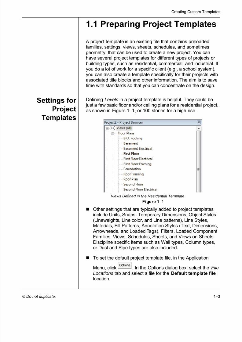
Defining Levels in a project template is helpful. They could be just a few basic floor and/or ceiling plans for a residential project,as shown in Figure 1–1 , or 100 stories for a high-rise.
Figure 1–1
Other settings that are typically added to project templatesinclude Units, Snaps, Temporary Dimensions, Object Styles(Lineweights, Line color, and Line patterns), Line Styles,Materials, Fill Patterns, Annotation Styles (Text, Dimensions,
Arrowheads, and Loaded Tags), Filters, Loaded ComponentFamilies, Views, Schedules, Sheets, and Views on Sheets.Discipline specific items such as Wall types, Column types,or Duct and Pipe types are also included.
To set the default project template file, in the Application
Menu, click . In the Options dialog box, select the FileLocations tab and select a file for the Default template file location.
Views Defined in the Residential Template

7/28/2019 978-1-58503-677-6-1
http://slidepdf.com/reader/full/978-1-58503-677-6-1 6/70
Autodesk Revit 2012 BIM Management for Architecture, Structure and MEP
1–4 © Do not duplicate.
How to: Create a Project Template File
The first step in customizing a project template file is to createone where you can add the various settings, views, and other information. To save time, use an existing project template thatincludes some of the basics rather than starting from scratch.
1. In the Application Menu, expand (New) and click
(Project).2. In the New Project dialog box, select a template file to build
from or select None for a blank project file.3. In the Create new area, select Project template , as shown in
Figure 1–2 .
Project template fileshave the extension rte.
Figure 1–2
4. Click .5. If you do not specify a project template file, you are promptedto specify the initial unit system for the project: Imperial or Metric , as shown in Figure 1–3 .
Figure 1–3
6. Add settings, families, views, and more as needed to the newfile.
7. Save the project template file.

7/28/2019 978-1-58503-677-6-1
http://slidepdf.com/reader/full/978-1-58503-677-6-1 7/70
Creating Custom Templates
© Do not duplicate. 1–5
SpecifyingUnits
Even though you select Imperial or Metric units when you createthe project template, you can set up the Project Units withspecific formats and options. For example, if you are working ona Civil project where everything is set up in feet, you wouldspecify Decimal Feet as the Length Format. For an internationalmetric project, you can specify whether the length units areMeters, Centimeters, or Millimeters.
How to: Set Up Project Units
1. In the Manage tab > Settings panel, click (Project Units)or type UN .
2. In the Project Units dialog box, as shown on the left inFigure 1–4 , in the Format column, click the button next to theunit type that you want to modify. The related Format dialogbox opens, as shown on the right in Figure 1–4 .
Figure 1–4
3. Set the Units , Rounding , and other options as needed.4. In the Project Units dialog box, you can also select the
Discipline (Common by default) and change the Unit formatfor each discipline. The other options are Structural andElectrical . HVAC and Piping are also included in Autodesk ® Revit ® MEP software.
5. Click to close each dialog box.

7/28/2019 978-1-58503-677-6-1
http://slidepdf.com/reader/full/978-1-58503-677-6-1 8/70
Autodesk Revit 2012 BIM Management for Architecture, Structure and MEP
1–6 © Do not duplicate.
Format Options
Each unit has specific formatting options. The option is grayedout if it is not applicable to that unit type.
The Use project settings and Show + for positive values options are grayed out when setting units for the project. Thisdialog box is also used when creating dimension styles or specifying label formats. At that point, the options areavailable.
Units Select the type of units in the Units drop-down list, asshown in Figure 1–5 .
Figure 1–5
Rounding Specify how precisely you want the dimensions to berounded. The options depend on the Units you
selected.Unit Symbol If you are using metric units, you can select a unit
symbol, such as cm for centimeters or None .
Suppress trailing0’s
(For decimal-based units) If selected, this optionremoves any trailing 0s. For example, it displays 1.5instead of 1.50 if you are using two decimal places.
Suppress 0 feet (Length and Slope only.) If selected, this optionremoves the 0 in front of a dimension in inches only.For example, instead of 0’-4”, you see 4”.
Use digit
grouping
If selected, the unit uses the Decimal symbol/digit
grouping specified in the Project Units dialog box, asshown in Figure 1–6 .
Figure 1–6
Suppress spaces (Length and Slope only) If selected, this optionremoves the spaces between the feet and inches, sothat a dimension reads 1’-2" rather than 1’ - 2".

7/28/2019 978-1-58503-677-6-1
http://slidepdf.com/reader/full/978-1-58503-677-6-1 9/70
Creating Custom Templates
© Do not duplicate. 1–7
Snap Settings The Snaps dialog box controls Dimension Snaps, which are theincrements you see in temporary dimensions, and Object Snaps ,which are the points on elements that you can select. It also liststemporary snap overrides that can be used as keyboardshortcuts within an active command. In the Manage tab >
Settings panel, click (Snaps) to open the dialog box, asshown in Figure 1–7 .
Figure 1–7
Snap overrides are listed as keyboard shortcuts inparentheses, next to the corresponding snap. When a snapoverride is used, the cursor finds that specified snap type inyour view until something is selected.
7/28/2019 978-1-58503-677-6-1
http://slidepdf.com/reader/full/978-1-58503-677-6-1 10/70
Autodesk Revit 2012 BIM Management for Architecture, Structure and MEP
1–8 © Do not duplicate.
CustomizingShortcuts
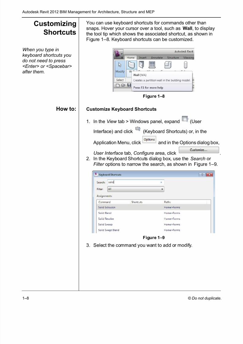
You can use keyboard shortcuts for commands other thansnaps. Hover your cursor over a tool, such as Wall , to displaythe tool tip which shows the associated shortcut, as shown inFigure 1–8 . Keyboard shortcuts can be customized.
When you type inkeyboard shortcuts youdo not need to press<Enter> or <Spacebar>after them.
Figure 1–8
How to: Customize Keyboard Shortcuts
1. In the View tab > Windows panel, expand (User
Interface) and click (Keyboard Shortcuts) or, in the
Application Menu, click and in the Options dialog box,
User Interface tab, Configure area, click .2. In the Keyboard Shortcuts dialog box, use the Search or
Filter options to narrow the search, as shown in Figure 1–9 .
Figure 1–9
3. Select the command you want to add or modify.

7/28/2019 978-1-58503-677-6-1
http://slidepdf.com/reader/full/978-1-58503-677-6-1 11/70
Creating Custom Templates
© Do not duplicate. 1–9
4. In the Press new keys area, type in the shortcut you want to
use, as shown in Figure 1–10 , and click .
Figure 1–10
5. Click when you are finished.
To remove shortcuts, select the shortcut and click
.
You can import or export the shortcut file to be used in other stations of Revit than the one where they were created.When you export to XML, all of the commands are exported.You can then add the shortcuts you want in the XML file andimport them back into your program.
TemporaryDimension
Settings
Temporary dimensions display when you draw or edit buildingelements in Autodesk ® Revit ® software. By default, theymeasure from the center lines of walls to the center lines of openings, as shown in Figure 1–11 .
Figure 1–11
When you move a witness line to another element or part of an element, the location is remembered within the currentsession of program.
7/28/2019 978-1-58503-677-6-1
http://slidepdf.com/reader/full/978-1-58503-677-6-1 12/70
Autodesk Revit 2012 BIM Management for Architecture, Structure and MEP
1–10
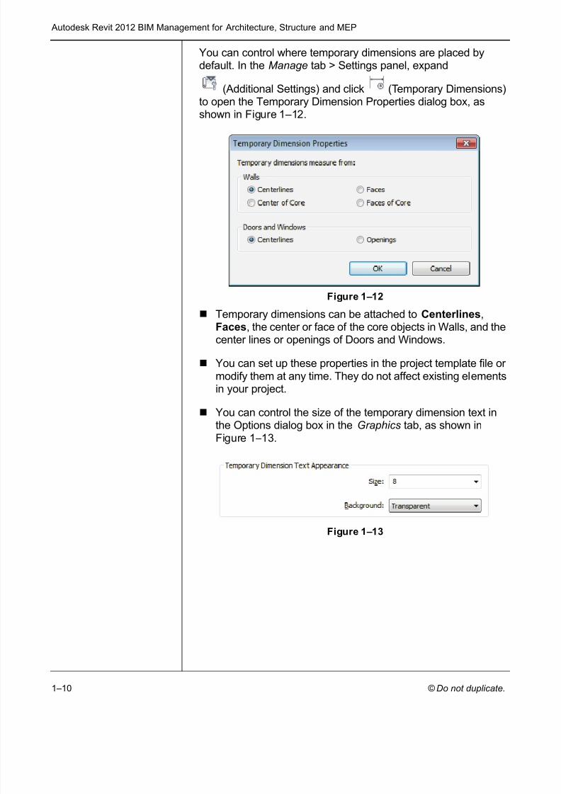
You can control where temporary dimensions are placed bydefault. In the Manage tab > Settings panel, expand
(Additional Settings) and click (Temporary Dimensions)to open the Temporary Dimension Properties dialog box, asshown in Figure 1–12 .
Figure 1–12
Temporary dimensions can be attached to Centerlines ,Faces , the center or face of the core objects in Walls, and thecenter lines or openings of Doors and Windows.
You can set up these properties in the project template file or modify them at any time. They do not affect existing elementsin your project.
You can control the size of the temporary dimension text inthe Options dialog box in the Graphics tab, as shown inFigure 1–13 .
Figure 1–13

7/28/2019 978-1-58503-677-6-1
http://slidepdf.com/reader/full/978-1-58503-677-6-1 13/70
Creating Custom Templates
© Do not duplicate. 1–11
1.2 Customizing AnnotationStyles
You can customize Annotation styles in your project template fileincluding dimensions, text types, and tags, as shown inFigure 1–14 .
Figure 1–14
Text, Dimensions, and Arrowheads are all system families. This
means they have a standard set of parameters, which you canmodify and save as a type. Callout, Section, and Elevation tagscan be modified within Autodesk Revit. Most other tags arecreated using families.
Creating TextTypes
Text types are used to standardize text formatting (such as thefont, text height, etc.), as shown in Figure 1–15 . They can becreated for to both annotative text and Model Text.
Figure 1–15
The Text command places text at the height you need for thefinal plot (e.g., 1/8” high). The view scale controls the heightof the standard text in the views.

7/28/2019 978-1-58503-677-6-1
http://slidepdf.com/reader/full/978-1-58503-677-6-1 14/70
Autodesk Revit 2012 BIM Management for Architecture, Structure and MEP
1–12
The Model Text command places text that is typically usedon the building, such as the signage shown in Figure 1–16 .Text types for Model Text should be the full height of the textand are not affected by the view scale.
Figure 1–16
How to: Create a Text Type
1. Start the Text or Model Text command. (Place the ModelText and select it.)
2. In Properties, click .
3. In the Type Properties dialog box, click .4. Type a new name.5. Modify the parameters as needed for the new type, as shown
for annotation text in Figure 1–17 .
Figure 1–17
6. Click if you want to create another type.
7. Click twice if you are finished.

7/28/2019 978-1-58503-677-6-1
http://slidepdf.com/reader/full/978-1-58503-677-6-1 15/70
Creating Custom Templates
© Do not duplicate. 1–13
Dimensions Dimensions are one of the more complex system families interms of the number of parameters you can modify. You cancreate three typical types: linear, radial, and angular, as shown inFigure 1–18 , as well as types for Spot Elevation , Spot Coordinate , and Spot Slope .
Figure 1–18
Values for the parameters (such as text size, witness lineextension, etc.) are the actual plot size for these elements.The view scale controls how large they are in the specificview.
How to: Create Dimension Types
1. In the Annotate tab > Dimension panel, expand the
Dimension panel title, as shown in Figure 1–19 , and clicknext to the dimension type you want to create.
Figure 1–19

7/28/2019 978-1-58503-677-6-1
http://slidepdf.com/reader/full/978-1-58503-677-6-1 16/70
Autodesk Revit 2012 BIM Management for Architecture, Structure and MEP
1–14
2. In the Type Properties dialog box, click tocreate a new type.
3. Modify the parameters as needed for the new type.
4. Click when you are finished.
Dimension Type OptionsThe dimension type parameters include the Graphics of thedimension (such as Tick Mark and Line Weight ), as shown inFigure 1–20 , for Linear dimensions, and the Text formatting(scroll down in the Type Parameter dialog box to view).
Figure 1–20
For Linear dimensions, you can specify a Leader Type ,
Shoulder Length, Leader Tick Mark, and Show Leader WhenText Moves that is used when the text is pulled away from thedimension string. You can also specify the text inserted for Equality Text (the default is still EQ).
You can specify a Text Background option. If you set thevalue to opaque , it automatically masks any elements behindthe text. If it is set to transparent , anything the text overlapsis still visible.

7/28/2019 978-1-58503-677-6-1
http://slidepdf.com/reader/full/978-1-58503-677-6-1 17/70
Creating Custom Templates
© Do not duplicate. 1–15
If you are dimensioning doors and windows by their widthsrather than their centers, you can also have the openingheight displayed with the dimension. Select the ShowOpening Height option.
Arrowheads A variety of arrowhead types are supplied with Autodesk Revit,
including open and filled arrow styles, tick marks, and dots. Youcan also create custom styles by duplicating an existing styleand defining the parameters, such as the Arrow Style shown inFigure 1–21 . In the Manage tab > Settings panel, expand
(Additional Settings) and click (Arrowheads) to open thedialog box.
Figure 1–21
Arrowheads are used by both text (with a leader) anddimensions.
Callout,Elevation, and
Section Tags
Callout, Elevation, and Section tags can be modified to suit anoffice standard. In the Manage tab>Settings panel, expand
(Additional Settings) and click (Callout), (Elevation),
or (Section). Then, in the Type Properties dialog box,duplicate an existing tag and make changes to the typeparameters.
The Callout Tags parameters specify a Callout Head and theCorner Radius of the callout box, as shown in Figure 1–22 .
Figure 1–22

7/28/2019 978-1-58503-677-6-1
http://slidepdf.com/reader/full/978-1-58503-677-6-1 18/70
Autodesk Revit 2012 BIM Management for Architecture, Structure and MEP
1–16
The Elevation Tags parameter is the Elevation Mark . You canselect from a variety of types that come with Autodesk Revit, asshown in Figure 1–23 . For example, you may want to set theexterior elevation mark to display a square body and the detailnumber on the sheet where it is placed.
Figure 1–23
The Section Tags parameters include both the Section Head and Section Tail , as well as the Broken Section Display Style , asshown in Figure 1–24 .
Figure 1–24
Once you set up these tags, you can connect them with the
tag types used in the (Callout), (Elevation), and
(Section) commands. In Properties, click andset up the type parameters, as shown for a Building Elevationin Figure 1–25 .
Figure 1–25

7/28/2019 978-1-58503-677-6-1
http://slidepdf.com/reader/full/978-1-58503-677-6-1 19/70
Creating Custom Templates
© Do not duplicate. 1–17
Loaded Tags You can load tags, such as door, window, and wall tags, asshown in Figure 1–26 , into a project template. Having thespecific tags required for your projects increases adherence tocompany standards.
Figure 1–26
Tags are created as separate family files (RFA) and stored in the
Library. In the Tags dialog box, as shown in Figure 1–27 , you caneasily load the tags you need from the Library into the projecttemplate Therefore, when you start the Tag command, the oneyou need is available.
Figure 1–27

7/28/2019 978-1-58503-677-6-1
http://slidepdf.com/reader/full/978-1-58503-677-6-1 20/70
Autodesk Revit 2012 BIM Management for Architecture, Structure and MEP
1–18
How to: Specify Loaded Tags
1. In the Annotate tab > Tag panel, expand the panel title and
click (Loaded Tags).
2. In the Tags dialog box , click .3. In the Library, open the Annotations folder.
4. Select the required tags and click . Hold down<Ctrl> to select multiple tags.
5. When you have loaded all of the tags that you typically need
for a project, click .

7/28/2019 978-1-58503-677-6-1
http://slidepdf.com/reader/full/978-1-58503-677-6-1 21/70
Creating Custom Templates
© Do not duplicate. 1–19
Practice 1a Preparing Templates for Autodesk Revit
In this practice you will create a new project template file, modifythe units, snaps, temporary dimensions, and add several newlevels. You will create several text types, add a dimension stylethat uses arrows, as shown in Figure 1–28 , and load typical tagsinto the project template file.
Estimated time for completion: 15 minutes.
Figure 1–28
Task 1 - Establish a project template file.
1. In the Application Menu, expand (New) and click
(Project).
2. In the New Project dialog box, select the default template file
and Project template and click .
3. In the Quick Access Toolbar, click (Save) and save thetemplate in your class directory as Midrise-Template.rte .
4. In the Manage tab > Settings panel, click (Project Units)or type UN . In the Project Units dialog box, set the formats asfollows:
Length:Units Feet and Fractional Inches
Rounding To the nearest 1/16"
Suppress 0 feet Check
Angle:
Rounding 0 decimal places

7/28/2019 978-1-58503-677-6-1
http://slidepdf.com/reader/full/978-1-58503-677-6-1 22/70
Autodesk Revit 2012 BIM Management for Architecture, Structure and MEP
1–20
5. Click to close the Units dialog box.
6. Set the Snaps and Temporary Dimensions as needed.
7. Switch to an elevation view.
8. Change Level 2 to 16’-0" . Add three more levels above the
current levels, at 12’-0” apart. Add two levels below Level 1and set them 10’-0” apart. Rename these to Basement 1 and Basement 2 , as shown in Figure 1–29 .
Figure 1–29
If you draw the levels using (Level), you can selectthe Make Plan View option in the Options Bar to createthe associated views.If you copy the existing levels, you need to create theplan views and ceiling plan views. In the View tab >
Create panel, expand (Plan Views) and click
(Floor Plan) and/or (Reflected Ceiling Plan).Rename above ground levels and corresponding viewsto match the other levels in the HVAC sub-discipline (3 -Mech, 4 - Mech, etc) and expand the ??? node andselect all of the new ceiling plans. In Properties, changethe Sub-Discipline to HVAC .
9. Switch back to the Level 1 floor plan view and save theproject template.

7/28/2019 978-1-58503-677-6-1
http://slidepdf.com/reader/full/978-1-58503-677-6-1 23/70
Creating Custom Templates
© Do not duplicate. 1–21
Task 2 - Preset annotation types.
1. Create the following text types:
2. Create or modify a Linear Dimension type and change theUnits Format Rounding to the nearest 1/8" . Modify theangular dimension type to use arrowheads. Modify other parameters if required. You can create an additional arrowtype if time permits.
3. Load the following tags into the project template:
4. Save the project template.
1/8” Arial Use the default, but set the Height to 1/8” .
1/8” Hand Use a hand-lettering Font , such as Comic Sans MS , andselect Italic .
3/32” Hand Same as above with a Height of 3/32” .
1/4” Title Use the font of your choice, in bold.
1" Title Duplicate 1/4" Title and change the Height to 1"
Architectural Casework, furniture, and furniture systems
Civil Parking and planting
FireProtection
Sprinkler-Symbol-Pendent on Drop andSprinkler-Symbol-Pendent
Electrical Lighting Fixture tag and Panel Name
Architectural Wall and Floor
Structural Select any different Structural tags you might want to usein place of those already loaded
7/28/2019 978-1-58503-677-6-1
http://slidepdf.com/reader/full/978-1-58503-677-6-1 24/70
Autodesk Revit 2012 BIM Management for Architecture, Structure and MEP
1–22
1.3 Creating Title Blocks
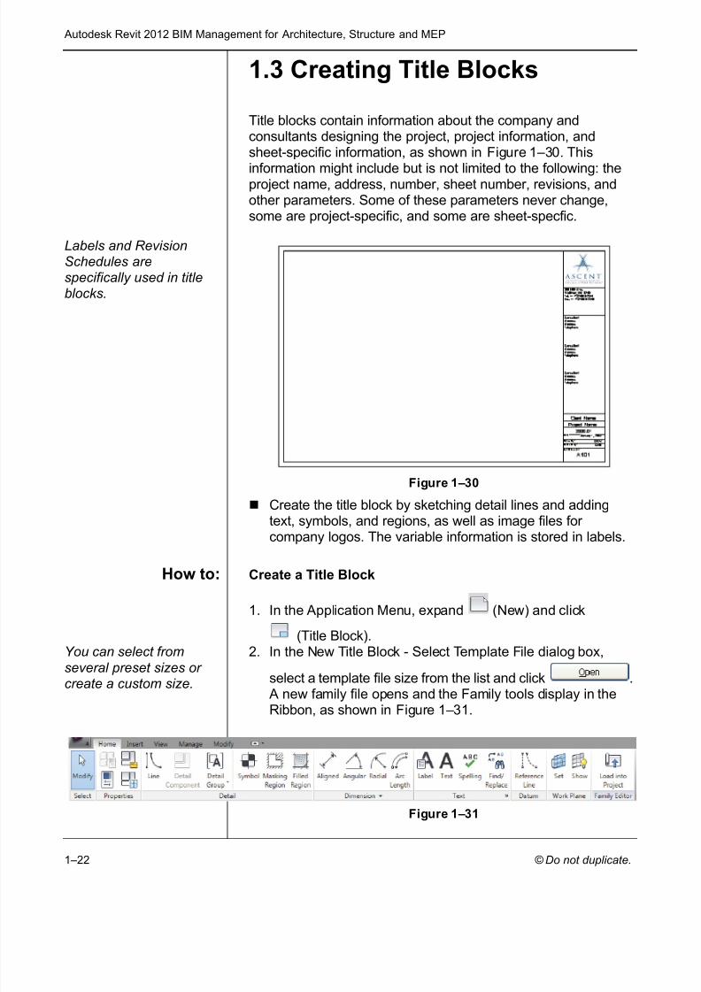
Title blocks contain information about the company andconsultants designing the project, project information, andsheet-specific information, as shown in Figure 1–30 . This
information might include but is not limited to the following: theproject name, address, number, sheet number, revisions, andother parameters. Some of these parameters never change,some are project-specific, and some are sheet-specfic.
Labels and RevisionSchedules arespecifically used in titleblocks.
Figure 1–30
Create the title block by sketching detail lines and adding
text, symbols, and regions, as well as image files for company logos. The variable information is stored in labels.
How to: Create a Title Block
1. In the Application Menu, expand (New) and click
(Title Block).You can select fromseveral preset sizes or create a custom size.
2. In the New Title Block - Select Template File dialog box,
select a template file size from the list and click .
A new family file opens and the Family tools display in theRibbon, as shown in Figure 1–31 .
Figure 1–31
7/28/2019 978-1-58503-677-6-1
http://slidepdf.com/reader/full/978-1-58503-677-6-1 25/70
Creating Custom Templates
© Do not duplicate. 1–23
If you select a template with a standard size, a rectangleof that size displays in the view.If you select New Size , a rectangle with dimensionsdisplays. Edit the dimensions to modify the size.
3. Add dimensions, lines, filled regions, symbols, text, labels,etc., as needed.
4. Save the file and close it.
Dimensions in the family file are not displayed when the titleblock is inserted.
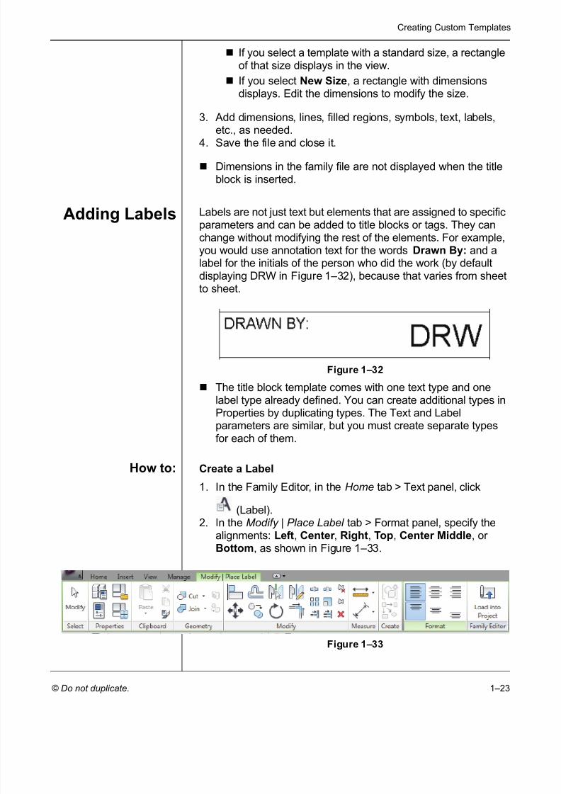
Adding Labels Labels are not just text but elements that are assigned to specificparameters and can be added to title blocks or tags. They canchange without modifying the rest of the elements. For example,you would use annotation text for the words Drawn By: and alabel for the initials of the person who did the work (by default
displaying DRW in Figure 1–32 ), because that varies from sheetto sheet.
Figure 1–32
The title block template comes with one text type and onelabel type already defined. You can create additional types in
Properties by duplicating types. The Text and Labelparameters are similar, but you must create separate typesfor each of them.
How to: Create a Label
1. In the Family Editor, in the Home tab > Text panel, click
(Label).2. In the Modify | Place Label tab > Format panel, specify the
alignments: Left , Center , Right , Top , Center Middle , or Bottom , as shown in Figure 1–33 .
Figure 1–33

7/28/2019 978-1-58503-677-6-1
http://slidepdf.com/reader/full/978-1-58503-677-6-1 26/70
Autodesk Revit 2012 BIM Management for Architecture, Structure and MEP
1–24
3. Click in the view window to place the label, as shown inFigure 1–34 .
Figure 1–34
4. In the Edit Label dialog box shown in Figure 1–35 , select alabel in the Category Parameters list and double-click or click
(Add parameter[s] to label). You can select more thanone by holding down <Ctrl>.
Figure 1–35
5. Enter the Sample Value and specify any other options asneeded.
If you are using several parameters in one label, selectthe Wrap between parameters only and Break (incolumn) options to separate them while still permitting aword wrap.
Click (Add Parameter) to create a new parameter for the project.
Click (Move parameter up) and (Moveparameter down) to reorder multiple parameters.
If you select a numerical parameter, click (Editparameter’s units format) to change, if necessary.
6. Click when you have finished editing the label.

7/28/2019 978-1-58503-677-6-1
http://slidepdf.com/reader/full/978-1-58503-677-6-1 27/70
Creating Custom Templates
© Do not duplicate. 1–25
7. Rotate or stretch the label as needed (as shown inFigure 1–36 ), or select a point for an additional label.
Figure 1–36
8. Click (Modify) or press <Esc> twice to finish thecommand.
AddingRevision
Schedules
A table of revisions included in a project and/or sheet is typicallyadded to a company title block. In Autodesk Revit, you cancreate a Revision Schedule that is then linked to the RevisionTable in the project.
How to: Add Revision Schedules to Title Blocks
1. In the Family Editor, in the View tab>Create panel, click
(Revision Schedule).2. In the Revision Properties dialog box, select the fields you
want to use. Several are already selected for you, as shownin Figure 1–37 .
Figure 1–37
3. Modify the options in the Sorting/Grouping and Formatting tabs as needed.

7/28/2019 978-1-58503-677-6-1
http://slidepdf.com/reader/full/978-1-58503-677-6-1 28/70
Autodesk Revit 2012 BIM Management for Architecture, Structure and MEP
1–26
4. In the Appearance tab, select how you want to build theschedule: from the Top-down or Bottom-up . You can alsoset the Height to Variable or User-Defined .
5. Click . The schedule view displays.6. In the Project browser, open the Sheet view (it has no name).7. Drag and drop the schedule onto the sheet and modify the
controls, as shown in Figure 1–38 .
If the height is set toUser-Defined , anadditional control isdisplayed at the bottom of the schedule. Use it to set the height of theschedule.
Figure 1–38
In the Options Bar, you can change the Rotation on the Sheet to None , 90 ° Clockwise , or 90 ° Counterclockwise .
Adding Sheetsto Project
Templates
You can set up project templates using the custom title block intwo ways. Add all or most of the sheets typically needed for aproject, or create a Sheet List Schedule that can be used toautomatically create sheets when they are needed.
How to: Load a Title Block into a Project Template
1. Open the project template.2. Return to the custom title block family. In the Family Editor
panel, click (Load into Project).3. In the Load into Projects dialog box, select the project you
want the title block loaded into and click . If onlyone project is open, it is loaded into the project automatically.
4. The title block is now available when you create a sheet.
If the title block family is not open, select Insert tab > Load
from Library panel and click (Load Family) to access it, or
click in the New Sheet dialog box.

7/28/2019 978-1-58503-677-6-1
http://slidepdf.com/reader/full/978-1-58503-677-6-1 29/70

7/28/2019 978-1-58503-677-6-1
http://slidepdf.com/reader/full/978-1-58503-677-6-1 30/70
Autodesk Revit 2012 BIM Management for Architecture, Structure and MEP
1–28
4. Depending on the complexity of your sheet naming scheme,you can also modify items on the Filter and Sorting/Grouping tabs.
5. Click when you are finished.6. You are placed in the schedule view with the two parameters
displayed. Stretch out the columns as shown in Figure 1–41 .
Figure 1–41
7. In the Modify Sheet List tab, as shown in Figure 1–42 , in the
Rows panel, click (New).
Figure 1–42
8. A new row is added below the schedule names. If no sheetsare in the project, it comes in automatically as A101 andUnnamed .
9. Add as many rows as you have sheets. If you are using anumbering scheme such as A1xx for site plans, A2xx for Floor Plans, A3xx for Detail plans, etc., then you shouldrename the sheet number for the first row of a set beforecreating more rows so that they increment automatically.
10.Enter the name of each sheet. Once you have added a newname, it is available in the drop-down list, as shown inFigure 1–43 .
Figure 1–43
7/28/2019 978-1-58503-677-6-1
http://slidepdf.com/reader/full/978-1-58503-677-6-1 31/70
Creating Custom Templates
© Do not duplicate. 1–29
How to: Use Sheet List Tables
1. Create a new sheet. In the Sheet List Schedule view, in the
Modify Sheet List tab>Create panel, click (New Sheet),You can also access the command on the View tab or right-click on Sheets in the Project browser.
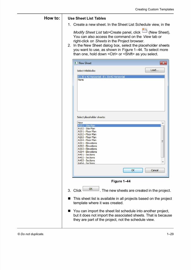
2. In the New Sheet dialog box, select the placeholder sheetsyou want to use, as shown in Figure 1–44 . To select morethan one, hold down <Ctrl> or <Shift> as you select.
Figure 1–44
3. Click . The new sheets are created in the project.
This sheet list is available in all projects based on the projecttemplate where it was created.
You can import the sheet list schedule into another project,but it does not import the associated sheets. That is becausethey are part of the project, not the schedule view.

7/28/2019 978-1-58503-677-6-1
http://slidepdf.com/reader/full/978-1-58503-677-6-1 32/70
Autodesk Revit 2012 BIM Management for Architecture, Structure and MEP
1–30
Presetting aStarting View
When you create a project template or a project, it can help tospecify a starting view. This can be any of the standard viewssuch as plan, elevation, 3D view, or one specifically created.Often this is a Drafting View, as shown in Figure 1–45 , or LegendView with information about the project or the cover sheet for theproject.
Figure 1–45
How to: Set a Starting View
1. Set up the view or sheet you want to use as the starting view.2. In the Manage tab > Manage Project panel, click
(Starting View).3. In the Starting View dialog box, select the view you want to
use as shown in Figure 1–46 .
Figure 1–46
4. Click .
5. Save the project or project template. The next time the fileopens to this view.
7/28/2019 978-1-58503-677-6-1
http://slidepdf.com/reader/full/978-1-58503-677-6-1 33/70
Creating Custom Templates
© Do not duplicate. 1–31
Practice 1b Creating Title Blocks
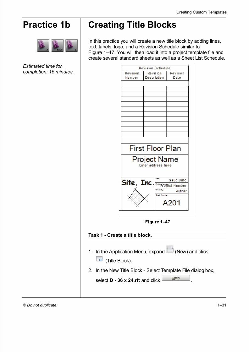
In this practice you will create a new title block by adding lines,text, labels, logo, and a Revision Schedule similar toFigure 1–47 . You will then load it into a project template file andcreate several standard sheets as well as a Sheet List Schedule.
Estimated time for completion: 15 minutes.
Figure 1–47
Task 1 - Create a title block.
1. In the Application Menu, expand (New) and click
(Title Block).
2. In the New Title Block - Select Template File dialog box,
select D - 36 x 24.rft and click .
7/28/2019 978-1-58503-677-6-1
http://slidepdf.com/reader/full/978-1-58503-677-6-1 34/70
Autodesk Revit 2012 BIM Management for Architecture, Structure and MEP
1–32
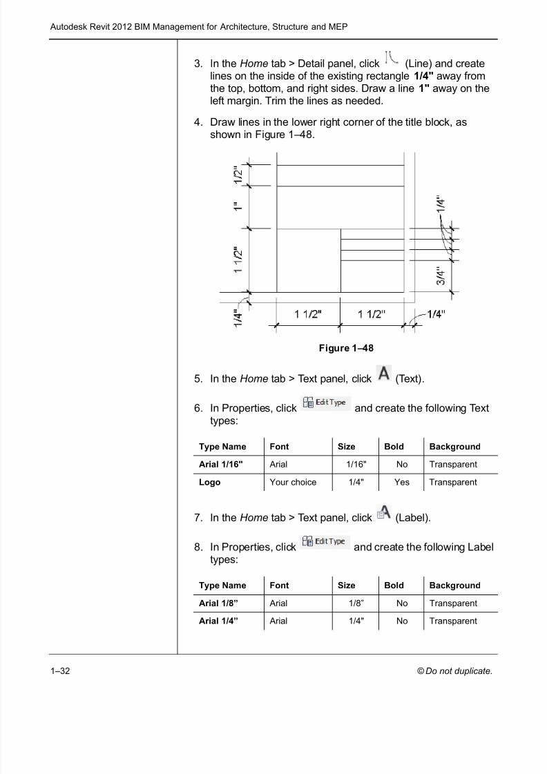
3. In the Home tab > Detail panel, click (Line) and createlines on the inside of the existing rectangle 1/4" away fromthe top, bottom, and right sides. Draw a line 1" away on theleft margin. Trim the lines as needed.
4. Draw lines in the lower right corner of the title block, as
shown in Figure 1–48 .
Figure 1–48
5. In the Home tab > Text panel, click (Text).
6. In Properties, click and create the following Texttypes:
7. In the Home tab > Text panel, click (Label).
8. In Properties, click and create the following Labeltypes:
Type Name Font Size Bold Background
Arial 1/16" Arial 1/16" No Transparent
Logo Your choice 1/4" Yes Transparent
Type Name Font Size Bold Background
Arial 1/8” Arial 1/8” No Transparent
Arial 1/4” Arial 1/4" No Transparent
7/28/2019 978-1-58503-677-6-1
http://slidepdf.com/reader/full/978-1-58503-677-6-1 35/70
Creating Custom Templates
© Do not duplicate. 1–33
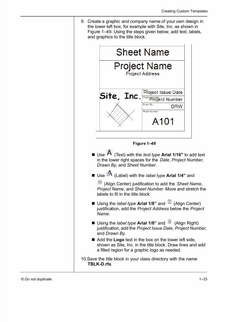
9. Create a graphic and company name of your own design inthe lower left box, for example with Site, Inc. as shown inFigure 1–49 . Using the steps given below, add text, labels,and graphics to the title block.
Figure 1–49
Use (Text) with the text type Arial 1/16" to add textin the lower right spaces for the Date , Project Number ,Drawn By , and Sheet Number .
Use (Label) with the label type Arial 1/4” and
(Align Center) justification to add the Sheet Name ,Project Name , and Sheet Number . Move and stretch thelabels to fit in the title block.
Using the label type Arial 1/8” and (Align Center) justification, add the Project Address below the Project Name .
Using the label type Arial 1/8” and (Align Right) justification, add the Project Issue Date , Project Number ,and Drawn By .
Add the Logo text in the box on the lower left side,shown as Site, Inc. in the title block. Draw lines and adda filled region for a graphic logo as needed.
10.Save the title block in your class directory with the nameTBLK-D.rfa .
7/28/2019 978-1-58503-677-6-1
http://slidepdf.com/reader/full/978-1-58503-677-6-1 36/70
Autodesk Revit 2012 BIM Management for Architecture, Structure and MEP
1–34
Task 2 - Add a Revision Schedule.
1. In the title block Family Editor, in the View tab > Create panel,
click (Revision Schedule).
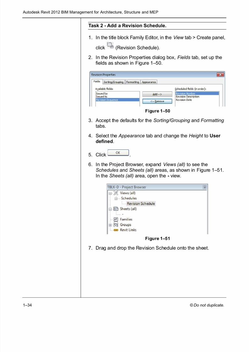
2. In the Revision Properties dialog box, Fields tab, set up thefields as shown in Figure 1–50 .
Figure 1–50
3. Accept the defaults for the Sorting/Grouping and Formatting tabs.
4. Select the Appearance tab and change the Height to User defined .
5. Click .
6. In the Project Browser, expand Views (all) to see theSchedules and Sheets (all) areas, as shown in Figure 1–51 .In the Sheets (all) area, open the - view.
Figure 1–51
7. Drag and drop the Revision Schedule onto the sheet.

7/28/2019 978-1-58503-677-6-1
http://slidepdf.com/reader/full/978-1-58503-677-6-1 37/70
Creating Custom Templates
© Do not duplicate. 1–35
8. Move it above the sheet name and resize it to display severallines, as shown in Figure 1–52 .
Figure 1–52
9. Save and close the title block.
Task 3 - Set up sheets in a project template using the newtitle block.
1. Open the project template Midrise-Template.rte that youcreated in the previous practice. If you did not complete theprevious practice, open the project from your class folder:
/Architectural/ Midrise-Template-A .rte /MEP/ Midrise-Template-MEP.rte /Structural/ Midrise-Template-S.rte
2. In the View tab > Sheet Composition panel, click (Sheet).
3. In the New Sheet dialog box, click .
4. In the Load Family dialog box, navigate to your class folder,select TBLK-D.rfa that you just created, and click
. If you did not complete the previous task, openthe project from your class folder:
/Architectural/ TBLK-D-A . rte /MEP/ TBLK-D-MEP .rte /Structural/ TBLK-D-S .rte
5. Select the title block that you just loaded and click .
6. In the Project Browser, select the sheet and rename it toCS000 – Cover Sheet .
7/28/2019 978-1-58503-677-6-1
http://slidepdf.com/reader/full/978-1-58503-677-6-1 38/70
Autodesk Revit 2012 BIM Management for Architecture, Structure and MEP
1–36
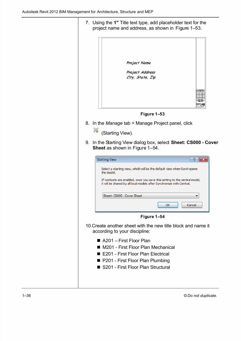
7. Using the 1" Title text type, add placeholder text for theproject name and address, as shown in Figure 1–53 .
Figure 1–53
8. In the Manage tab > Manage Project panel, click
(Starting View).
9. In the Starting View dialog box, select Sheet: CS000 - Cover Sheet as shown in Figure 1–54 .
Figure 1–54
10.Create another sheet with the new title block and name itaccording to your discipline:
A201 – First Floor PlanM201 - First Floor Plan MechanicalE201 - First Floor Plan ElectricalP201 - First Floor Plan PlumbingS201 - First Floor Plan Structural
7/28/2019 978-1-58503-677-6-1
http://slidepdf.com/reader/full/978-1-58503-677-6-1 39/70
Creating Custom Templates
© Do not duplicate. 1–37
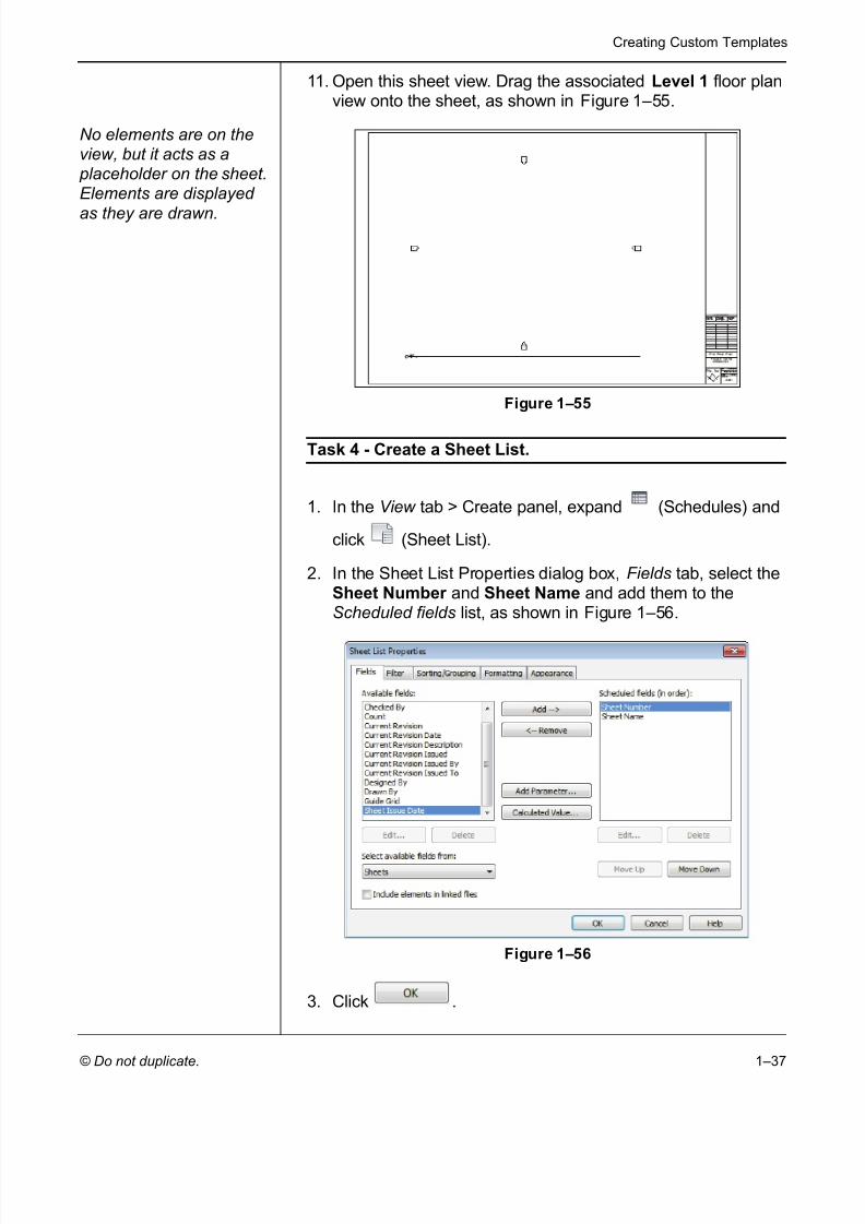
11. Open this sheet view. Drag the associated Level 1 floor planview onto the sheet, as shown in Figure 1–55 .
No elements are on theview, but it acts as a
placeholder on the sheet.Elements are displayed
as they are drawn.
Figure 1–55
Task 4 - Create a Sheet List.
1. In the View tab > Create panel, expand (Schedules) and
click (Sheet List).
2. In the Sheet List Properties dialog box, Fields tab, select theSheet Number and Sheet Name and add them to theScheduled fields list, as shown in Figure 1–56 .
Figure 1–56
3. Click .

7/28/2019 978-1-58503-677-6-1
http://slidepdf.com/reader/full/978-1-58503-677-6-1 40/70
Autodesk Revit 2012 BIM Management for Architecture, Structure and MEP
1–38
4. The Sheet List schedule opens with the two existing sheetslisted. Stretch out the columns, as shown for an architecturalproject in Figure 1–57 .
Figure 1–57
5. In the Modify Sheet List tab > Rows panel, click (New).
6. Add floor plans to match the levels, as shown for anarchitectural project in Figure 1–58 .
Figure 1–58
7. In the Modify Sheet List tab > Create panel, click (NewSheet). The list displays the plans you added to the SheetList display, but the sheets already in the project do not, asshown in Figure 1–59 .
Figure 1–59
8. Cancel out of the dialog box.
9. If time permits, create additional placeholder sheets for various other views.
10.Save the project template.

7/28/2019 978-1-58503-677-6-1
http://slidepdf.com/reader/full/978-1-58503-677-6-1 41/70
Creating Custom Templates
© Do not duplicate. 1–39
1.4 View Templates
View templates enable you to specify all of the view propertiesand visibility options for a view by selecting another view or aview template as a base. For example, you can create a furniture
plan view template that sets the scale, detail level, and visibilityof objects so that everything except the furniture displays inhalftone, as shown in Figure 1–60 .
Figure 1–60
View templates can be applied to specific views when you create
a project template file. You can also apply and create viewtemplates to existing and new views.
Applying ViewTemplates
Apply view templates to a view by setting them up in ViewProperties and then applying the default view template or a newview template.
These tools are available on the View tab > Graphics panel
under (View Template), or when you right-click on a viewin the Project Browser.
If a view template is preset in View Properties, you canupdate the properties by reapplying the view template. In theProject Browser, right-click on the view and select ApplyDefault View Template or in the View tab > Graphics panel,
expand (View template) and click (Apply defaulttemplate to current view).

7/28/2019 978-1-58503-677-6-1
http://slidepdf.com/reader/full/978-1-58503-677-6-1 42/70
Autodesk Revit 2012 BIM Management for Architecture, Structure and MEP
1–40
How to: Apply a View Template
1. Select one or more views in the Project Browser. (Hold down<Ctrl> or <Shift> to select multiple views.)
2. Right-click in the Project Browser and select Apply ViewTemplate… , or on the View tab > Graphics panel, expand
(View Template) and click (Apply new template tocurrent view.)3. Select the view template you want to use from the Names list
in the Apply View Template dialog box, as shown inFigure 1–61 . Several standard view templates are availablewhen you create a project using one of the Autodesk Revitproject templates.
Figure 1–61
4. If you do not want the entire view template to be applied tothe selected view, clear the check mark in the Include column
for the parameters you do not want to include. You can alsocreate overrides to the view template by changing parameter values.
5. Click to finish.

7/28/2019 978-1-58503-677-6-1
http://slidepdf.com/reader/full/978-1-58503-677-6-1 43/70
Creating Custom Templates
© Do not duplicate. 1–41
To limit the number of view templates that display, you canfilter the list by selecting an option in the Show type drop-down list, as shown in Figure 1–62 .
Figure 1–62
If you select the Apply automatically to new views of sametype option, it becomes the default view template for all newviews of the same type. For example, if the view you areworking with is a section, all new section views take on thesettings of the view template that you specify.
You can apply view templates to any views as many times asneeded.
Creating ViewTemplates
Many view templates come with Autodesk Revit, but you mightneed to create your own custom view types that are best appliedby view template. You can create a view template from the viewsettings in an existing view or through the View Template dialogbox.
How to: Create a View Template from an Existing View
1. Set up a view the way you want it with Scale , Detail Level ,Visibility Graphic Overrides , and other View Settings .
2. In the Project Browser, right-click on the view and selectCreate View Template from View or, on the View tab>
Graphics panel, expand (View Template) and click
(Create Template from Current View).3. In the New View Template dialog box, type a name for the
view template.
4. Click .5. In the View Template dialog box, make other adjustments as
needed and click .

7/28/2019 978-1-58503-677-6-1
http://slidepdf.com/reader/full/978-1-58503-677-6-1 44/70
Autodesk Revit 2012 BIM Management for Architecture, Structure and MEP
1–42
How to: Create a View Template
1. On the View tab > Graphics panel, expand (View
Template) and click (View Template Settings). The ViewTemplates dialog box opens, as shown in Figure 1–63 .
Figure 1–63
2. In the Name list, select a view similar to the one you want to
create and click (Duplicate).3. In the New View Template dialog box, type a new name for
the view template and click .4. Modify the View Properties parameter values as needed and
select which parameters you want to include in the viewtemplate.
5. Click to finish.
Not all view types have the same view parameters. For example, 3D views have options for Rendering andPerspectives that plans do not have. When you apply a viewtemplate across view types, only the options that are mutualare updated.

7/28/2019 978-1-58503-677-6-1
http://slidepdf.com/reader/full/978-1-58503-677-6-1 45/70
Creating Custom Templates
© Do not duplicate. 1–43
One of the parameters in views is the Detail Level . There arethree options: Coarse , Medium , and Fine . You can modifythe table of scales that are related to the levels. On the
Manage tab > Project Settings panel, expand (AdditionalSettings) and select Detail Level . The View scale-to-detaillevel correspondence dialog box opens, as shown in
Figure 1–64 .
Figure 1–64
The only parameter saved to a view template for scheduleviews is the appearance of the schedule.
Visibility/Graphic
OverridesFilters
Visibility/Graphic Overrides filters can speed up the process of specifying categories that are modified in View Templates. Anyview has is a filter for modifying the visibility of graphics byelement type. You might want to display certain elements inhalftone, or with a different color or lineweight in specific views.For example, a fire evacuation plan might have walls withdifferent fire ratings that display with thicker lineweights, asshown in Figure 1–65 . By creating these filters and then applyingthem in a view template, you can reuse them without having torecreate them each time.
Figure 1–65
Create the filters using the Filters command before applyingthem through the Visibility/Graphic Overrides dialog box. It isbest to create filters in a project template.

7/28/2019 978-1-58503-677-6-1
http://slidepdf.com/reader/full/978-1-58503-677-6-1 46/70
Autodesk Revit 2012 BIM Management for Architecture, Structure and MEP
1–44
How to: Create Filters
1. On the View tab > Graphics panel, click (Filters). TheFilters dialog box opens, as shown in Figure 1–66 .
Figure 1–66
2. In the Filters area, click (New) or (Duplicate). Name
the new filter and click .3. In the Categories area, select the categories to include in the
filter. Use and to help select thecategories.
4. In the Filter Rules area, select what you what to Filter by , the
filter operator(s), and the value for the filter. If more than onecategory is selected, the Filter by list is limited to parametersshared by the categories you selected. You can create morethan one filter rule. They are applied in order. Set Filter by toNone if you do not want to filter by parameters. Filter operators are shown in Figure 1–67 .
Figure 1–67
5. Click to save the changes and remain in the
dialog box, or click to finish.

7/28/2019 978-1-58503-677-6-1
http://slidepdf.com/reader/full/978-1-58503-677-6-1 47/70
Creating Custom Templates
© Do not duplicate. 1–45
How to: Apply Visibility/Graphic Overrides Filters
1. Type VG or VV or in the View tab > Graphics panel, click
(Visibility/ Graphics) to open the Visibility/GraphicOverrides dialog box. Select the Filters tab, as shown inFigure 1–68 .
Figure 1–68
2. Click to add a filter to the list.3. In the Add Filters dialog box, select the filter(s) you want to
add and click .
If the filter you want is not defined, click toopen the Filters dialog box, where you can define a newfilter or edit an existing one.
4. In the Visibility/Graphic Overrides dialog box, assign theoverrides you want for the filter. For example, you might wantitems to be Halftone , as shown in Figure 1–69 .
Figure 1–69
5. Click .

7/28/2019 978-1-58503-677-6-1
http://slidepdf.com/reader/full/978-1-58503-677-6-1 48/70
Autodesk Revit 2012 BIM Management for Architecture, Structure and MEP
1–46
Practice 1c View Templates for Architecturaland Structural Projects
Autodesk Revit
Architecture and Autodesk Revit Structure
In this practice you will create filters that you will use in astructural view template, and apply the view template to severalstructural plan views, as shown in Figure 1–70 . When the filter isworking correctly you can add the same information to a projecttemplate file.
Estimated time for completion: 15 minutes.
Figure 1–70
Task 1 - Create Filters
1. Open the project from your class folder:
/Architectural/ Office-A.rvt/Structural/ Office-S.rvt
2. On the View tab > Graphics panel, click (Filters).
3. In the Filters dialog box, click (New). Name the new filter
All But Structural and click .
4. In the Categories area, click , and then clear Columns , all categories starting with Structural , and Walls .
Click .
5. Click (New). Name the new filter Non-Structural Walls
and click .
6. In the Categories area, click as needed and selectWalls .

7/28/2019 978-1-58503-677-6-1
http://slidepdf.com/reader/full/978-1-58503-677-6-1 49/70
Creating Custom Templates
© Do not duplicate. 1–47
7. In the Filter Rules area, set Filter by to Structural Usage ,equals , and Non-bearing , as shown in Figure 1–71 .
Figure 1–71
8. Click .
Task 2 - Create a View Template
1. In the Project Browser, in the Floor Plans area, right-click onthe Level 1 view and select Create View Template FromView .
2. Name the new view template Structural Plan and click
.
3. In the View Templates dialog box, set the View Scale to1/16”=1’-0” and the Detail Level to Coarse .
4. Next to V/G Override Filters , click TheVisibility/Graphic Overrides dialog box opens with the Filter tab selected.
5. Click .
6. In the Add Filters dialog box, select the two filters you just
created and click .
7. Place a check mark in the Halftone column for both filters.Continue working in the Visibility/Graphics Overrides dialogbox.
8. In the Annotation Categories tab, turn off everything exceptGrids and all Structural annotations and tags.
9. In the Model Categories tab, turn off items such asCasework , Furniture , Furniture Systems and Plumbing ,and Mechanical equipment .

7/28/2019 978-1-58503-677-6-1
http://slidepdf.com/reader/full/978-1-58503-677-6-1 50/70
Autodesk Revit 2012 BIM Management for Architecture, Structure and MEP
1–48
10.Click to close the Visibility/Graphic Overrides
dialog box, and click to complete the viewtemplate.
Task 3 - Apply a View Template to Several Views
1. In the Floor Plans area, use Duplicate with Detailing on theLevel 1 , Level 2 , Level 3 , and Level 4 views. Rename themas Structural – Level 1 , Structural – Level 2 , Structural –Level 3 , and Structural – Level 4 .
2. Select the new Structural views.
3. Right-click and select Apply View Template…
4. In the Apply View Template dialog box, select the Structural
Plan view template you just created and click toapply it.
5. Look at the different views and compare them to the standardfloor plan views. Finish with the Level 1 view.
6. Save the project.

7/28/2019 978-1-58503-677-6-1
http://slidepdf.com/reader/full/978-1-58503-677-6-1 51/70
Creating Custom Templates
© Do not duplicate. 1–49
Practice 1d View Templates for MEPProjects
Autodesk Revit MEP only
In this practice you will create velocity based filters for ductworkthat you will use in a mechanical view template, and apply theview template to a duplicated plan view, as shown inFigure 1–72 . When the filter is working correctly, you can add thesame information to a project template file.
Estimated time for completion: 15 minutes.
Figure 1–72
Task 1 - Create Filters
1. Open the project /MEP/ Office-MEP.rvt from your class
folder.
2. In the View tab > Graphics panel, click (Filters).
3. In the Filters dialog box, click (New). Name the new filter
Mechanical - Low Velocity and click .
4. In the Categories area, select Ducts and click .
5. In the Filter Rules area, set Filter by to Velocity , is less thanor equal to , and 1660 FPM , as shown in Figure 1–73 .
Figure 1–73

7/28/2019 978-1-58503-677-6-1
http://slidepdf.com/reader/full/978-1-58503-677-6-1 52/70
Autodesk Revit 2012 BIM Management for Architecture, Structure and MEP
1–50
6. Remain in the Filters dialog box, select the new
Mechanical-Low Velocity filter and click (Duplicate).Name it Mechanical-Medium/High Velocity and click
.
7. In the Filter Rules area, set Filter by to Velocity , is greater than , and 1660 FPM , as shown in Figure 1–74 .
Figure 1–74
8. Click .
Task 2 - Create a View Template
1. In the Project Browser, in the Mechanical > Floor Plans area,right-click on the 1 - Mech view and select Create ViewTemplate From View .
2. Name the new view template Velocity Duct Plan and click
.
3. Next to V/G Override Filters , click TheVisibility/Graphic Overrides dialog box opens with the Filter tab selected.
4. Click .
5. In the Add Filters dialog box, select the two filters you just
created and click .
6. For the Mechanical-Low Velocity filter, in theProjection/Surface > Lines column select Override .

7/28/2019 978-1-58503-677-6-1
http://slidepdf.com/reader/full/978-1-58503-677-6-1 53/70
Creating Custom Templates
© Do not duplicate. 1–51
7. In the Line Graphics dialog box, change Weight to 6 and theColor to an orange, as shown in Figure 1–75 . Click
.
Figure 1–75
8. Repeat for the Mechanical-Medium/High Velocity filter andset the Weight to 6 and the Color to a green. Click .
9. In the Visibility/Graphics Overrides dialog box, move the newfilters to the top of the list. For Mechanical-Exhaust , in theVisibility column, clear the checkbox as shown inFigure 1–76 .
Figure 1–76
10.Click to close the Visibility/Graphic Overrides
dialog box, and click to complete the viewtemplate.
7/28/2019 978-1-58503-677-6-1
http://slidepdf.com/reader/full/978-1-58503-677-6-1 54/70
Autodesk Revit 2012 BIM Management for Architecture, Structure and MEP
1–52
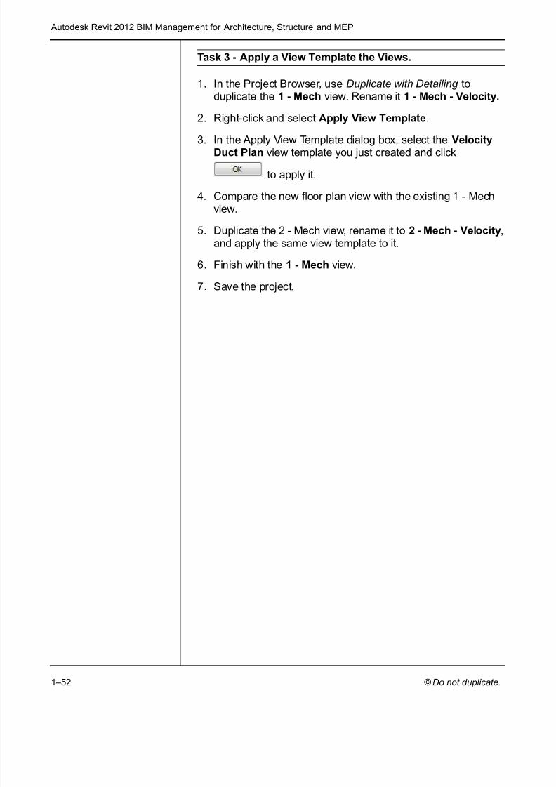
Task 3 - Apply a View Template the Views.
1. In the Project Browser, use Duplicate with Detailing toduplicate the 1 - Mech view. Rename it 1 - Mech - Velocity.
2. Right-click and select Apply View Template .
3. In the Apply View Template dialog box, select the VelocityDuct Plan view template you just created and click
to apply it.
4. Compare the new floor plan view with the existing 1 - Mechview.
5. Duplicate the 2 - Mech view, rename it to 2 - Mech - Velocity ,and apply the same view template to it.
6. Finish with the 1 - Mech view.
7. Save the project.
7/28/2019 978-1-58503-677-6-1
http://slidepdf.com/reader/full/978-1-58503-677-6-1 55/70
Creating Custom Templates
© Do not duplicate. 1–53
1.5 Settings for Mechanical andElectrical Projects
Autodesk Revit MEP only
In addition to the standard settings common to all Revit projects, Autodesk Revit MEP software also has specific Mechanical andElectrical settings that can be setup in a template or a project.
In Autodesk Revit MEP, the settings are found in the Manage
tab > Project Settings panel. Expand (MEP Settings) and
click (Mechanical Settings) or (Electrical Settings).
Additional types of settings include Load Classifications,Demand Factors, and Building/Space Type Settings.
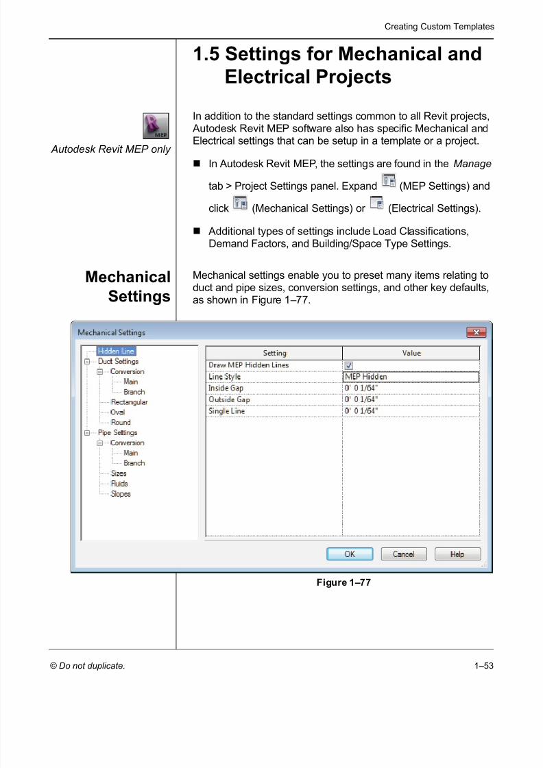
MechanicalSettings
Mechanical settings enable you to preset many items relating toduct and pipe sizes, conversion settings, and other key defaults,as shown in Figure 1–77 .
Figure 1–77

7/28/2019 978-1-58503-677-6-1
http://slidepdf.com/reader/full/978-1-58503-677-6-1 56/70
Autodesk Revit 2012 BIM Management for Architecture, Structure and MEP
1–54
Hidden Line
If the Draw MEP Hidden Lines option is selected, hidden linesare displayed to indicate pipes and ducts that are below other pipes and ducts, as shown in Figure 1–78 .
Figure 1–78The Line Style , Inside Gap , and Outside Gap options enableyou to specify how the hidden lines are displayed.
Duct Settings
For the Single Line Fittings option, the first two settings relateto how fittings are displayed in a single line view, as shown inFigure 1–79 . If the Use Annot. Scale for Single Line Fittings option is selected, the single line fittings are displayed at thesame size on every sheet, regardless of the view scale. The
Duct Fitting Annotation Size option enables you to specify thesize at which the fittings should be displayed.
Figure 1–79
The Air Density and Air Viscosity options are used when sizingthe ducts. The remaining options set the separators and suffixesthat are used for duct objects.

7/28/2019 978-1-58503-677-6-1
http://slidepdf.com/reader/full/978-1-58503-677-6-1 57/70
Creating Custom Templates
© Do not duplicate. 1–55
Conversion
The Conversion area is used to set the routing solutions for ductwork. The Elbow Angle Increment option sets the anglethat is used for elbows. The settings for the Main and Branchoptions can be set separately for each system type. You canspecify the Duct Type , Offset from level, and Flex Duct Type
settings (this is only applicable to branches), as shown inFigure 1–80 .
Figure 1–80
Rectangular, Oval, and Round
The Rectangular, Oval, and Round options enable you toadjust the sizing tables. The Size column lists all of the sizes.
You can click to add a size to the list and
to remove sizes from the list.
In addition, you can specify whether a size is displayed in thesize lists (to be available when you place a new duct or selectexisting ducts) or if the size is used by the sizing routine(automatic sizing of duct branches and systems).
For example, if you do not want the sizing routine to use any oddnumbered sizes, clear the Used in Sizing option for allodd-numbered sizes, as shown in Figure 1–81 .
Figure 1–81

7/28/2019 978-1-58503-677-6-1
http://slidepdf.com/reader/full/978-1-58503-677-6-1 58/70
Autodesk Revit 2012 BIM Management for Architecture, Structure and MEP
1–56
Pipe Settings
Most of the options in the Pipe Settings area are identical to or similar to those in the Duct Settings area.
Pipe Sizes
Pipe size settings are more complex due to the many differentmaterials and connections available. Each material has its ownroughness, connection types, schedule/types, and sizes thatcorrespond to each combination, as shown in Figure 1–82 . For example, Schedule 40 Carbon Steel with a Flanged Connectioncan have different sizes than Schedule 80 Carbon Steel with aFlanged Connection.
Figure 1–82
The actual size lists are identical in function to those for ducts,except for the inclusion of the ID (inside diameter) and OD(outside diameter) parameters.
To add a new material, connection, or schedule/type, click
(Add Material/Add Connection/Add Schedule).
To delete a material, connection or schedule, click
(Delete Material/Delete Connection/Delete Schedule).

7/28/2019 978-1-58503-677-6-1
http://slidepdf.com/reader/full/978-1-58503-677-6-1 59/70
Creating Custom Templates
© Do not duplicate. 1–57
Fluids
The Fluids area enables you to specify the viscosity and densityof fluids at different temperatures, as shown in Figure 1–83 . Youcan add or delete fluid types, and for each type, add or deletetemperatures.
Figure 1–83
Slopes
In the Slopes area, you can add or delete typical slopes used ina project, as shown in Figure 1–84 .
Figure 1–84
7/28/2019 978-1-58503-677-6-1
http://slidepdf.com/reader/full/978-1-58503-677-6-1 60/70
Autodesk Revit 2012 BIM Management for Architecture, Structure and MEP
1–58
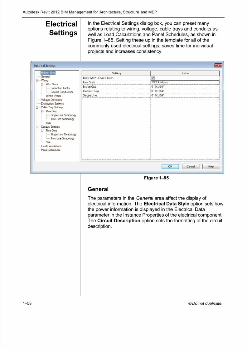
ElectricalSettings
In the Electrical Settings dialog box, you can preset manyoptions relating to wiring, voltage, cable trays and conduits aswell as Load Calculations and Panel Schedules, as shown inFigure 1–85 . Setting these up in the template for all of thecommonly used electrical settings, saves time for individualprojects and increases consistency.
Figure 1–85
General
The parameters in the General area affect the display of electrical information. The Electrical Data Style option sets howthe power information is displayed in the Electrical Dataparameter in the Instance Properties of the electrical component.The Circuit Description option sets the formatting of the circuitdescription.

7/28/2019 978-1-58503-677-6-1
http://slidepdf.com/reader/full/978-1-58503-677-6-1 61/70
Creating Custom Templates
© Do not duplicate. 1–59
Wiring
The Wiring area enables you to specify the ambient temperaturefor wiring and some annotation settings related to wiring. TheTick Mark families need to be preloaded into the template sothat they can be selected in this area, as shown in Figure 1–86 .
Figure 1–86
Wire Sizes
The Wire Size settings enable you to create new wire materials,temperature ratings, and insulation types. You can then specifythe ampacity, size, diameter, and if the size is used by the wiresizing tools.
The functionality in the Wire Sizes area is similar to that in thePipe Sizes and Fluids areas.
Correction Factor
The Correction Factor area enables you to specify the correctionfactors for different temperatures and for each wire type, asshown in Figure 1–87 .
Figure 1–87
7/28/2019 978-1-58503-677-6-1
http://slidepdf.com/reader/full/978-1-58503-677-6-1 62/70
Autodesk Revit 2012 BIM Management for Architecture, Structure and MEP
1–60
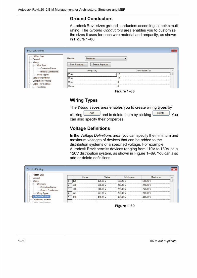
Ground Conductors
Autodesk Revit sizes ground conductors according to their circuitrating. The Ground Conductors area enables you to customizethe sizes it uses for each wire material and ampacity, as shownin Figure 1–88 .
Figure 1–88
Wiring Types
The Wiring Types area enables you to create wiring types by
clicking and to delete them by clicking . Youcan also specify their properties.
Voltage Definitions
In the Voltage Definitions area, you can specify the minimum andmaximum voltages of devices that can be added to the
distribution systems of a specified voltage. For example, Autodesk Revit permits devices ranging from 110V to 130V on a120V distribution system, as shown in Figure 1–89 . You can alsoadd or delete definitions.
Figure 1–89

7/28/2019 978-1-58503-677-6-1
http://slidepdf.com/reader/full/978-1-58503-677-6-1 63/70
Creating Custom Templates
© Do not duplicate. 1–61
Distribution Systems
The Distribution Systems area sets the distribution systems thatare available in your project, as shown in Figure 1–90 . You canedit the names by selecting them. The options for Phase arepreset and affect the options that are available in theConfiguration and Wires columns and whether L-L Voltage is
available. You can add more systems and delete existingsystems if they are not assigned to devices in the current project.
Figure 1–90
Cable Tray and Conduit Settings
Cable Trays and Conduits settings include annotation, Rise DropSymbology, and sizing, as shown in Figure 1–91 .
Figure 1–91
Load Calculations and Panel Schedules
The Load Calculations area gives you access to additional dialogboxes where you can setup Load Classifications and DemandFactors.
The Panel Schedules area enables you set up labels and other options for the default panel schedule.

7/28/2019 978-1-58503-677-6-1
http://slidepdf.com/reader/full/978-1-58503-677-6-1 64/70
Autodesk Revit 2012 BIM Management for Architecture, Structure and MEP
1–62
1.6 Settings for StructuralProjects
Autodesk Revit StructureOnly
In addition to the standard settings common to all Revit products, Autodesk Revit Structure has structural settings that need to be
customized. To access them, click (Structural Settings) inthe Manage tab > Project Settings panel.
Symbolic Representation
There are several tabs at the top of the Structural Settings dialogbox as shown in Figure 1–92 . The first tab, Symbolic Representation Settings , contains options that are mainly usedfor the graphical model and the common defaults.
Figure 1–92

7/28/2019 978-1-58503-677-6-1
http://slidepdf.com/reader/full/978-1-58503-677-6-1 65/70
Creating Custom Templates
© Do not duplicate. 1–63
The Symbolic Cutback Distance setting represents thedistance that cuts a framing member back from a column or intoanother framing member. This cutback distance is symbolic anddoes not affect the 3D view. For example, in plan, beams do notextend into the column and there is a gap between them, asshown in Figure 1–93 . The same connection in 3D displays thebeams 1” back from the column, which is more consistent with areal-world situation.
Figure 1–93
The Brace Symbols and Connection Symbols areas enable youto specify the kinds of symbols that are shown for the braces inplan, and for frame and shear connections. For many of theseitems, only one symbol is loaded into the default template.
Load Cases and Load Combinations
Two tabs are related to setting up Load Cases and LoadCombinations. These vary by project and by region and typicallyrequires the input of a company’s engineer.
7/28/2019 978-1-58503-677-6-1
http://slidepdf.com/reader/full/978-1-58503-677-6-1 66/70
Autodesk Revit 2012 BIM Management for Architecture, Structure and MEP
1–64
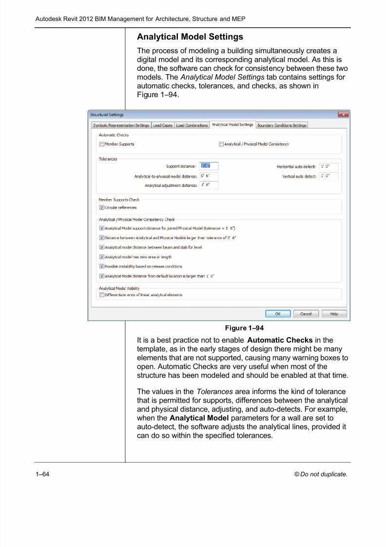
Analytical Model Settings
The process of modeling a building simultaneously creates adigital model and its corresponding analytical model. As this isdone, the software can check for consistency between these twomodels. The Analytical Model Settings tab contains settings for automatic checks, tolerances, and checks, as shown in
Figure 1–94 .
Figure 1–94
It is a best practice not to enable Automatic Checks in thetemplate, as in the early stages of design there might be manyelements that are not supported, causing many warning boxes toopen. Automatic Checks are very useful when most of thestructure has been modeled and should be enabled at that time.
The values in the Tolerances area informs the kind of tolerancethat is permitted for supports, differences between the analyticaland physical distance, adjusting, and auto-detects. For example,when the Analytical Model parameters for a wall are set toauto-detect, the software adjusts the analytical lines, provided itcan do so within the specified tolerances.

7/28/2019 978-1-58503-677-6-1
http://slidepdf.com/reader/full/978-1-58503-677-6-1 67/70
Creating Custom Templates
© Do not duplicate. 1–65
The Analytical/Physical Model Consistency Check area enablesyou to specify the kinds of consistencies to be checked for.
Boundary Condition Settings
In the last tab, you can select the family symbols used for boundary conditions, as shown in Figure 1–95 (from left to right:
Fixed , Pinned , Roller , and User ).
Figure 1–95
The structural templates typically include four boundarycondition families: Fixed , Pinned , Roller , and Variable . Theyare assigned to the corresponding boundary conditions, asshown in Figure 1–96 .
Figure 1–96
You can create new boundary condition families, load theminto the template, and select them from the drop-down lists asneeded.

7/28/2019 978-1-58503-677-6-1
http://slidepdf.com/reader/full/978-1-58503-677-6-1 68/70
Autodesk Revit 2012 BIM Management for Architecture, Structure and MEP
1–66
Chapter Review Questions
1. What are the various types of units you can set up in a projecttemplate?
2. Where do you set up a new text type? A new dimensiontype?
3. What is a label?
4. Give several examples of what might be included in a ViewTemplate.

7/28/2019 978-1-58503-677-6-1
http://slidepdf.com/reader/full/978-1-58503-677-6-1 69/70
Creating Custom Templates
© Do not duplicate. 1–67
Command SummaryButton Command Location
Apply Defaulttemplate toCurrent View
Ribbon: Manage tab>Settings panel>expand View TemplatesProject Browser: (right-click on aview )
Apply templateto current View
Ribbon: Manage tab>Settings panel>expand View TemplatesProject Browser: (right-click on aview )
Arrowheads Ribbon: Manage tab>Settings panel>expand Additional Settings
Callout Tags Ribbon: Manage tab>Settings panel>expand Additional Settings
Create ViewTemplate FromView
Ribbon: Manage tab>Settings panel>expand View TemplatesProject Browser: (right-click on aview )
DimensionTypes
Linear Angular RadialSpotElevationSpotCoordinateSpot Slope
Ribbon: Annotate tab>Dimensionspanel>expand the panel title
Elevation Tags Ribbon: Manage tab>Settingspanel>expand Additional Settings
Floor Plan Ribbon: View tab>Create panel>expand Plan Views
KeyboardShortcuts
Ribbon: View tab>Windowspanel> expand User InterfaceApplication Menu
Label Family Editor Ribbon: Create tab>Text panel
Loaded Tags Ribbon: Annotate tab>Tag panel>expand the panel title
New Title Block Application Menu: expand New>Title block
7/28/2019 978-1-58503-677-6-1
http://slidepdf.com/reader/full/978-1-58503-677-6-1 70/70
Autodesk Revit 2012 BIM Management for Architecture, Structure and MEP
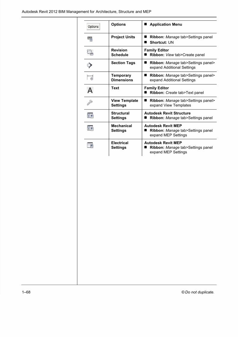
Options Application Menu
Project Units Ribbon: Manage tab>Settings panelShortcut: UN
RevisionSchedule
Family Editor Ribbon: View tab>Create panel
Section Tags Ribbon: Manage tab>Settings panel>expand Additional Settings
TemporaryDimensions
Ribbon: Manage tab>Settings panel>expand Additional Settings
Text Family Editor Ribbon: Create tab>Text panel
View TemplateSettings
Ribbon: Manage tab>Settings panel>expand View Templates
Structural
Settings
Autodesk Revit Structure
Ribbon: Manage tab>Settings panel
MechanicalSettings
Autodesk Revit MEPRibbon: Manage tab>Settings panelexpand MEP Settings
ElectricalSettings
Autodesk Revit MEPRibbon: Manage tab>Settings panelexpand MEP Settings


