31
Installation instruction Doc # 98030730-03 SEH series

Installation instruction
Doc # 98030730-03
SEH series

Page 2
Safety
SEH series Single - Installation instruction manual 98030730-03
This installation instruction is a complement to the "Operation Manual".
The machine is built according to the current status of technology and is safe to operate. However, due to its work processes the machine has parts and areas that cannot be protected without impairing the function and operating capacity of the unit. For this reason, good personal safety practice is required to protect personnel and equipment. Risks can arise from this equipment if it is used incorrectly by untrained personnel or for non-intended purposes.
• Before transport, assembly, commissioning, dismantling and maintenance, read and observe the machine operating manuals and safety notes!
• Read and understand the operating manual first during work is too late!
• Keep the operating manual accessible in close proximity to the machine.
• The generally valid, legal and other binding provisions for accident prevention and environmental protection in the respective country in
which the machine is being operated are considered a supplement to the operating manual (e.g. wearing personal protective gear such as
hard hat, safety shoes, etc.) Observe the attached notices and warning signs.
• Only work while wearing close fitting clothing, safety shoes and hard hat. Do not wear jewellery such as necklaces and rings. There is a
risk of injury from getting caught or being pulled in. Find a doctor immediately if there is any injuries or accidents.
Consequences of not complying with safety instructionsNon-compliance with safety instructions can result in danger both for personnel as well as for the environment and the machine. Non-compliance can lead to the forfeit of any compensation claims.
TABLE OF REVISIONSRev Description Date Comment00 Issued for production 2013-09-23 New product01 General revision 2014-03-06 Update parts and numbers to Fraco std02 General revision 2014-07-09 Added Installation instruction

Page 3
Installation instructions
98030730-03SEH series Single - Installation instruction manual
The following steps are general instruction for a typicalinstallation. Since all installations differs, some steps may notapply and some additional steps may be necessary. Always referto the engineering package containing the plans andspecifications for the installation details.
Step 1- Install the foundation slab following the requirements.- Install and anchor the base section into the foundation slab.- Install the buffer.
Attention!! When installing the base section, make sure yourespect the distance from the wall indicated in the engineeringpackage.
Step 2- Install the ground enclosure. Make sure the enclosure is
installed in the right direction (Depend on which side of themast the cabin is installed)
Step 3- Install 2 mast sections on the base.- Install the cable trolley by slipping it down the mast (optional)- Prepare the cabin (installation of cable holder, centrifugal
brake, drive motor and railing)- Using a crane, lift the cabin by its lifting points and insert it into
the mast sections.- Verify the alignment of the cabin and adjust the cabin rollers if
necessary.
Step 4- Complete the electrical connections leaving the junction box,
cable guide and support on the ground.
Step 5- Assemble 6 mast sections together on the ground- Using a crane, lift the assembled mast section.- Using a boom lift or scaffold for access, bolt the mast sections
together.
Step 6- Using the boom lift or scaffold for access, install the anchors.
Refer to the engineering package for the anchors levels.Attention!! No more than 30’ (9m) of mast section can beinstalled over the last anchor.
Step 7- Repeat step 5 and 6 until you reach half the total height of the
mast.- Install the junction box.- Complete the final electrical connections.
Step 8- Repeat step 5 and 6 until the you reach to total height of the
mast.IMPORTANT!! The last mast section needs to have the module 5 rail removed.
- install a cable guide every 20’.
Step 9- Install the limit switch cams.
Attention!! Make sure the limit switches shut off the circuit.
Step 10- Install the landing gates.

Page 4
Foundation slab
SEH series Single - Installation instruction manual 98030730-03
1. The foundation must be horizontal and have sufficient load bearing capacity.
2. Depending on the assembly height, concrete or thick steel sheeting (for example) can be used as load distributing base supports.
3. The size of the concrete pad depends on the installation (model, height number of car). Typically, a concrete pad should have a thickness of at least 12 in (300mm).
4. The size will vary from 13’9”x9’10” (4.2m x 3.0m) to 18’0”x10’0” (5.5m x 3.1m) for single unit and 13’9”x15’9” (4.2m x 4.8m) to 18’0”x16’1” (5.5m x 4.9m) for a double unit.
5. The foundation should be above ground or be drained.
6. If there is a risk of frost heave, the foundation must be isolated.
7. All foundation specifications should be detailed in the installation engineering package.
8. The total weight of the SEH and mast sections are transferred into the ground via the base unit support. (See operating manual for point load values)
Place the foundation slab on ground get high level to the enclosure door threshold. No drain is required
Place the foundation slab in level to ground get small level to the enclosure door threshold. No drain is required.
Place the foundation slab in level to ground get no/small level to the enclosure door threshold. Drain is required!
Page 5
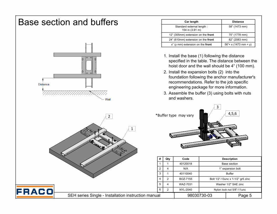
Base section and buffers
SEH series Single - Installation instruction manual 98030730-03
1. Install the base (1) following the distance specified in the table. The distance between the hoist door and the wall should be 4“ (100 mm).
2. Install the expansion bolts (2) into the foundation following the anchor manufacturer's recommendations. Refer to the job specific engineering package for more information.
3. Assemble the buffer (3) using bolts with nuts and washers.
# Qty Code Description1 1 40120018 Base section
2 4 N/A 1” expansion bolt
3 1 40110040 Buffer
4 2 BOZ-7155 Bolt 1/2”-13unc x 1-1/2” gr5 zinc
5 4 WAZ-7031 Washer 1/2" SAE zinc
6 2 NYL-2040 Nylon lock nut 5/8”-11unc
2
1
Car length DistanceStandard external length :
154 in (3.91 m)58” (1473 mm)
12” (305mm) extension on the front 70” (1778 mm)
24” (610mm) extension on the front 82” (2083 mm)
x” (y mm) extension on the front 56”+ x (1473 mm + y)
34,5,6*Buffer type may vary

Page 6
Extension beam and bottom beam
SEH series Single - Installation instruction manual 98030730-03
1. Place the extension beams (1).2. Adjust to the desired length.3. Assemble the extension beams (1) using bolts
with nuts and washers. (View A)4. Assemble the short bottom beams (2) to the
extension beams using bolts with nuts and washers. (View B)
# Qty Code Description1 2 35020088 Extension beam
2 2 35020145 Short bottom beam
3 8 BOZ-7135 Bolt 3/8”-16unc x 3” gr5 zinc
4 16 WAZ-7021 Washer 3/8” SAE zinc
5 8 NYL-2020 Nylon lock nut 3/8” - 16 unc
1View A
2
View B
3,4,53,4,5
B

Page 7
Bottom beam (cont.) and poles
SEH series Single - Installation instruction manual 98030730-03
1. Place the long bottom beams (1).
2. Assemble the poles (2) to the bottom beams (1) using bolts with nuts and washers.(View A)
3. Assemble the poles extension (3) to the poles (2) using bolts with nuts and washers (View B)
4. Anchor the poles by installing expansion bolts (3) into the foundation following the anchor manufacturer's recommendations. Tighten to 20 lb-ft (27 Nm) (View A)
B
A
View A View B
# Qty Code Description1 2 35020134 Long bottom beam
2 4 35020022 Pole
3 4 35020099 Pole extension
4 32 BOZ-7114 Bolt 3/8”-16unc x 1” gr5 zinc
5 54 WAZ-7021 Washer 3/8” SAE zinc
6 32 NYL-2020 Nylon lock nut 3/8” - 16 unc
7 8 N/A 3/8” expension bolt
1
2
3
4,5,6
4,5,6
7

Page 8
Enclosure doors
SEH series Single - Installation instruction manual 98030730-03
1. Assemble the bottom plates (1)(2) using bolts with nuts and washers. The bottom plates (1)(2) must be anchored to the bottom beams, poles and to each other. (View A, B and C)
View A View B View C
# Qty Code Description1 1 35020055 Bottom plate door
2 1 35020033 Bottom plate
3 6 BOZ-7125 Bolt 3/8
4 2 BOZ-7142 Bolt 3/8”-16unc x 2-1/2” gr5 zinc
5 16 WAZ-7021 Washer 3/8” SAE zinc
6 8 NYL-2020 Nylon lock nut 3/8” - 16 unc
6,5,3
6,5,4 6,5,3
1
2

Page 9
Enclosure doors (cont.)
SEH series Single - Installation instruction manual 98030730-03
1. Place the enclosure door (1).2. Fasten the enclosure door (1) to the pole and
bottom plate door, using bolts with nuts and washers. (View A,B and E)
3. Place the control panel (2).4. Fasten the control panel (2) to the pole bottom
plate and enclosure door (1) using bolts with nuts and washers. (View C and D)
View A View B View C View D
# Qty Code Description1 1 35020123 Enclosure door
2 1 35020044 Control panel
3 4 BOZ-8508 Carriage bolt 3/8”-16 unc x 4-1/2” Lg
4 7 BOZ-7125 Bolt 3/8”-16unc x 2-1/4” gr5 zinc
5 2 BOZ-7142 Bolt 3/8”-16unc x 4” gr5 zinc
6 34 WAZ-7021 Washer 3/8” SAE zinc
7 19 NYL-2020 Nylon lock nut 3/8” - 16 unc
8 6 BOZ-7114 Bolt 3/8”-16unc x 1” gr5 zinc
1
23,6,7
4,6,7 4,6,7 5,6,7
View E
3,6,7

Page 10
Enclosure walls
SEH series Single - Installation instruction manual 98030730-03
1. Place the ground enclosure sections (1) (2) (3) (4).
2. Fasten each sections using two bolts with nuts and washer on the bottom and two to four bolts with nuts and washer on each side. (View A, B and C)
View A View B View C
# Qty Code Description1 1 35020112 Ground enclosure 40” x 42.5”
2 1 35020101 Ground enclosure 40” x 96”
3 4 35020077 Ground enclosure 24” x 42.5”
4 7 35020066 Ground enclosure 24” x 96”
5 22 BOZ-7125 Bolt 3/8”-16unc x 2-1/4” gr5 zinc
6 106 BOZ-7142 Bolt 3/8”-16unc x 4” gr5 zinc
7 256 WAZ-7021 Washer 3/8” SAE zinc
8 128 NYL-2020 Nylon lock nut 3/8” - 16 unc
5,7,8 6,7,8 6,7,8
1
2
3
4

Page 11
Enclosure walls (cont.)
SEH series Single - Installation instruction manual 98030730-03
1. Place two short top beams (1) and two long top beams (2) over the enclosure.
2. Fasten the top beam (1) (2) to the pole, bottom plate and enclosure door (1) using bolts with nuts and washers. (View A)
View A
1 2
3 5,6,7
# Qty Code Description1 2 35020156 Short top beam
2 2 35020167 Long top beam
3 8 35020178 Bolt plate
4 26 BOZ-7142 Bolt 3/8”-16unc x 4” gr5 zinc
5 52 WAZ-7021 Washer 3/8” SAE zinc
6 26 NYL-2020 Nylon lock nut 3/8” - 16 unc

Page 12
Mast section
SEH series Single - Installation instruction manual 98030730-03
1. Install the mast section (1) on the base. The male section must face downward.
2. Assemble the mast section (1) to the base with 4 bolts with nuts and washer (View A). Bolts on top and nuts underneath (only for this mast section).
3. Secure the bolts with a tightening torque of 350 Nm (258 lbs-pi)
4. Repeat the steps 1 to 3 to add another mast section (1). Bolt underneath and nut on top. (View B)
IMPORTANT: All following mast section must have bolts underneath and nuts on top.
View A View B
# Qty Code Description1 2 35020156 SEH 650x650 mast section w/ rack
2 4 BOZ-7305 Bolt 1”-8unc x 6-1/2” gr8 yellow zinc assemblyw/ nut and washer
3 4 BOZ-7289 Bolt 1”-8unc x 10” gr8 zinc
4 8 WAZ-7073 Washer 1” gr8 zinc F-436
5 4 NYL-2061 Nylon lock nut 1”-8unc gr8 zinc

Page 13
Cable holder
SEH series Single - Installation instruction manual 98030730-03
1. Insert the cable holder (1) into the cage.
2. Secure it with a bolt with nut and washers. (View A)
View A
# Qty Code Description1 1 2000165 Cable holder
2 2 BOZ-7101 Bolt 5/16”-18unc x 3” gr5 zinc
3 4 WAZ-7017 Washer 5/16” SAE zinc
4 2 NYL-2015 Nylon lock nut 5/16” - 18 unc
1
23
4

Page 14
Cable trolley
SEH series Single - Installation instruction manual 98030730-03
1. Insert the cable trolley (1) unto the mast from the top.
Note:If there is an obstacle preventing the installation of the cable trolley (1) (i.e. if the cage is already in place), you must remove the tandem roller of the cable trolley, insert it unto the mast and install the tandem back.
Ensure that the cable trolley is not tight on the mast section. It needs to be able to ride the mast easily without left to right movement.
# Qty Code Description
1 1 40110017 or 40110028 Cable guide trolley (right or left)
1

Page 15
Installation of cage
SEH series Single - Installation instruction manual 98030730-03
1. Take off both upper load rollers (1) and the safety pins (2). (view A)
2. Lift the cage using the hoisting rings. Place the cage against the mast carefully. Attention at the safety device.
3. Reinstall the upper load rollers (1) and the safety pins (2).
4. Adjust the guide roller. The distance between the mast pipe and the guide roller must be less than 1 mm. (see guide roller detail)
5. Adjust the upper load rollers (1). The car must be parallel to the mast.
View AGuide roller detail
Hoisting rings Safety gear
2
1 Guide roller
Mast section
# Qty Code Description1 2 2000100 Load rollers
2 4 2000185 Safety pins

Page 16
Railing
SEH series Single - Installation instruction manual 98030730-03
1. Install the railing (1) (2) (3) (4) (5) into the railing pocket of the cage. And secure it using bolts and nuts. (View A)
2. Secure the railing together using bolts with nuts and washers. (View B)
3. Secure the resistance and the main control panel to the railing as shown on view C and D.
# Qty Code Description1 4 17040046 Railing 12” x 4’0”
2 2 17040024 Railing 2’10” x 4’0”
3 1 17040013 Railing 3’5” x 4’0”
4 2 17040057 Railing 5’1” x 3’7”
5 2 17040035 Railing 2’10” x 4’0” with rubber
6 2 40330910 Clamping plate 20.5”
7 4 BOZ-7095 Bolt 5/16”-18unc x 2-1/2”
8 8 WAZ-7017 Washer 5/16” SAE zinc
# Qty Code Description9 12 NYL-2020 Nylon lock nut 3/8”-16unc
10 2 40470117 U-bolt 2.5”
11 4 NYL-2015 Nylon lock nut 5/16”-18unc
12 10 BOZ-7105 Bolt 3/8”-16unc x 3/4” gr 5 zinc
13 10 FSQ-0021 Weld nut 3/8-16unc
14 8 BOZ-7130 Bolt 3/8”-16unc x 2-1/2” gr 5 zinc
15 8 WAZ-7021 Washer 3/8” SAE zinc
View A View B
View C View D
Resistance
Main control panel
12,13 14,15,9
10
11
7,8,9
6
1
4
1
2
32
1
45
Railing pocket

Page 17
Machinery
SEH series Single - Installation instruction manual 98030730-03
1. Install the mast section and drive unit (1).2. Release the locking pin and use the brake
release handle to release the motor brake slowly until the drive unit (1) touch the cage.
3. Insert the pivot shaft (2) and lock it using bolt with nut and washer (view A).
# Qty Code Description1 2 11050018 Drive unit
2 4 40420055 Pivot shaft machinery attachment
3 8 WAZ-7017 Washer 5/16” SAE zinc
4 4 NYL-2015 Nylon lock nut 5/16” - 18 unc
View A
1
2
3,4
Locking pin
Brake release handle

Page 18
Self erecting device
SEH series Single - Installation instruction manual 98030730-03
1. Insert the self erecting device (1) into the hole of the drive unit.
2. Lock it in place using the included locking pin (2). (View A)
When using the self erecting device:1. Fill the cage with erections parts (max 3300 lbs
(1500 kg)).2. Plug the controller into the outlet from the power
panel3. Operate the hoist from the roof with the
controller.4. Use the self erecting device (1) to place mast
sections and other erection parts.
# Qty Code Description1 1 20030083 Self erecting device
2 1 GOU-5040 Locking pin
View A2
1
Power panel

Page 19
Electrical installation overview
SEH series Single - Installation instruction manual 98030730-03
NOTES:
The machine must be set up and dismantled according to the “Operating manual" and under supervision by an authorized person specified by the contractor.
Connect the cable following the electrical layout (see next page)
The operator's panel (AS3) must always be installed on the building side of the car
Inside car
11060020Brake resistor
40310031Control panel(AS1)
20030049Junction box (AX1)
20030027Cable support with guide
20030027Cable guide
11060019Power panel (AS2)
43010042Operator’s panel (AS3)
40110017 or 40110028Cable Guide trolley
40810025Ground box (AL0)
Power source provided by client (480V 60hz) (Transformer need to be installed on 600V installation – Refer to the job site specific engineering package for more information)
Operator’s panel alternative position
Operator’s panel (AS3)
Control panel (AS1)

Page 20
Electrical connections
SEH series Single - Installation instruction manual 98030730-03
IMPORTANT: Cables to install are in bold

Page 21
Junction box
SEH series Single - Installation instruction manual 98030730-03
1. Install the junction box (1) to the mast section using bolts with nuts and washers. The junction box (1) can either be installed in the middle of a mast section (option 1), or at the junction of two mast section (option 2)
IMPORTANT: The junction box must be installed higher than the middle of the mast (overall height), to have enough cable for the cable guide trolley.
View A View B
2,3,4 2,3,4
1
1
Option 1(Mast intersection)
Option 2(Middle of the mast)
# Qty Code Description1 2 20030049 Junction box
2 4 BOZ-7220 Bolt 5/8”-11unc x 5” gr5 zinc
3 8 WAZ-7041 Washer 5/8” SAE zinc
4 4 NYL-2040 Nylon lock nut 5/8” - 11 unc

Page 22
Cable guide and cable guide with support
SEH series Single - Installation instruction manual 98030730-03
1. Attach the cable guide (1) or the cable guide with support (2) to the mast section using bolts with nuts and washers. The cable guide (1) (2) must be installed in the middle of a mast section, under the horizontal member.
2. Install a cable guide (1) every 15 ft (4.5 m) maximum. Install the cable guide with support (2) one mast section under the junction box.
3. Make sure the bracket are perpendicular with the mast and have a clearance with the cabin and the cable trolley.
View A View B
Cable guide Cable guide with support
11
3,4,5 3,4,5
# Qty Code Description1 1 20030016 Cable guide
2 1 20030027 Cable guide with support
3 4 BOZ-7220 Bolt 5/8”-11unc x 5” gr5 zinc
4 8 WAZ-7041 Washer 5/8” SAE zinc
5 4 NYL-2040 Nylon lock nut 5/8” - 11 unc

Page 23
Electric cable installation
SEH series Single - Installation instruction manual 98030730-03
1. Connect the power line to the ground box. Verify that the power input respect the specifications for the specific unit.
2. Connect the ground box to the junction box and attach the cable to the mast using cable ties.
3. Connect the junction box to the power panel. The cable must go down the cable guide, go through the cable guide trolley up to the unit, into the cable holder.
4. Connect grounds of ground box, power panel and resistance. Screw the grounds to the structure.
NOTE: During installation, there are not enough mast to install the junction box to. An installation cable without cable guide trolley should be used until half of the mast has been installed.
Ground box
Mast
Junction box Cable guide
Cable guide trolley
Cable holder Power panel Inside power panel

Page 24
Mast tie installation
SEH series Single - Installation instruction manual 98030730-03
1. Place the wall tie fixations (2) and wall tie structure (1) in the mast section, fasten with screws. (view A)
# Qty Code Description1 1 21010015 Wall tie structure for 650x650 mast
2 2 21010037 Wall tie fixation
3 8 BOZ-7200 Bolt 5/8”-11unc x 2” gr 5 zinc
4 8 WAA-1015 Washer 11/16” A325 galvanized
5 8 NYL-2040 Nylon lock nut 5/8”-11unc
6 4 BOZ-7250 Bolt 3/4”-10unc x 5” gr 5 zinc
7 4 WAZ-7051 Washer 3/4” SAE zinc
8 4 NYL-2050 Nylon lock nut 3/4”-10unc
2
1
View A
3,4,5
6,7,83,4,5

Page 25
Mast tie installation (cont.)
SEH series Single - Installation instruction manual 98030730-03
1. Attention, make sure that wall withstand the calculated wall forces, for more information see the operation manual and specific engineering package.
2. Take off the turnbuckle screws and install the anchor plates (1) on the wall. Use expansion bolts or chemical anchor (Detail A). Make sure the angle of the turnbuckle will not be more than 15° (Detail B) and that you respect the distance L and opening B given in your specific engineering package
3. Install and adjust the turnbuckles (2), fasten the screws. Attention, make sure that the distance according to picture do not exceed 9.5’’ (240 mm). (Detail C)
4. Use the turnbuckle to adjust the mast. Lock the turnbuckle! (Detail D)
5. Attention, for more detailed information concerning the maximal distance between ties, screws and overhang, see the operation manual and specific engineering package.
# Qty Code Description
1 2 240300100 SHE concrete anchor plate
2 3 - Turnbuckle
3 2 BOZ-7308 Bolt 1”-8unc x 7” gr8 yellow zinc w/nut and washer
4 3 BOZ-7261 Bolt 1”-8unc x 5” gr5 zinc
5 3 WAZ-7071 Washer 1” SAE zinc
6 3 NYL-2060 Nylon lock nut 1”-8unc
7 2 BOZ-7308 Bolt 1”-8unc x 7” gr8 yellow zinc w/nut and washer
8 6 BOZ-7250 Bolt 3/4”-10unc x 5” gr 5 zinc
9 6 WAZ-7040 Washer 11/16” zinc
10 6 NYL-2050 Nylon lock nut 3/4”-10unc
Max distance:9.5 in (240 mm)
Detail A
Expansion bolt orchemical anchor
Lock the turnbuckle
Detail B
Detail D
Detail C
1
2
3
5,6,7
8,9,10

Page 26
Limit switch cams - Bottom
SEH series Single - Installation instruction manual 98030730-03
1. Place the cam (1) according to the pictures. 2. Adjust the cams and fasten with two screws on
each (2,3,4).3. Adjust the sensors on the car.
NOTE: If using a pit, the distance shall be readjusted so the cage stops in level with the bottom level floor.
Attention!! Make sure that limit switches shut off the circuit.
Attention!! Make sure that the cage stop in level with the landing level. Otherwise adjust the curves in the mast.
Measure from here
1
# Qty Code Description1 1 20030061 Bottom limit switch cam
2 4 BOZ-7155 Bolt 1/2"-13unc x 1-1/2" gr5 zinc
3 8 WAZ-7031 Washer 1/2" SAE zinc
4 4 NYL-2030 Nylon lock nut 1/2"-13unc
2,3,4

Page 27
Limit switch cams - Top
SEH series Single - Installation instruction manual 98030730-03
Measure from here
# Qty Code Description1 1 20030072 Top limit switch cam
2 4 BOZ-7155 Bolt 1/2"-13unc x 1-1/2" gr5 zinc
3 8 WAZ-7031 Washer 1/2" SAE zinc
4 4 NYL-2030 Nylon lock nut 1/2"-13unc
1. Place the cam (1) according to the pictures. 2. Adjust the cams and fasten with two screws on
each (2,3,4).3. Adjust the sensors on the car.
Attention!! Make sure that limit switches shut off the circuit.
Attention!! Make sure that the cage stop in level with the landing level. Otherwise adjust the curves in the mast.
1
2,3,4
Measure from the top of the rack

Page 28
Limit switch cams - Landing
SEH series Single - Installation instruction manual 98030730-03
# Qty Code Description1 1 20030050 Landing limit switch cam
2 4 BOZ-7155 Bolt 1/2"-13unc x 1-1/2" gr5 zinc
3 8 WAZ-7031 Washer 1/2" SAE zinc
4 4 NYL-2030 Nylon lock nut 1/2"-13unc
1. Place the cam (1) according to the pictures. 2. Adjust the cams and fasten with two screws on
each (2,3,4).3. Adjust the sensors on the car. 4. Install a limit switch cam at every landing
desired (except the top and bottom landing)
Attention!! Make sure that limit switches shut off the circuit.
Attention!! Make sure that the cage stop in level with the landing level. Otherwise adjust the curves in the mast.
1
2,3,4

Page 29
Limit switch panel
SEH series Single - Installation instruction manual 98030730-03
LS1 Extreme HI
LS2 Auto stop
LS5 Extreme LOW
LS11 Stop HI
LS10 Stop LOW
LS4 Floor level
LS4 Floor level
Inside car
Limit switch panel
Attention!! The LS2 Auto stop limit switch is bi-directional. After installing the car or after maintenance, make sure it is oriented correctly (upward when on base landing, downward on top landing)

Page 30
Door selector
SEH650 Single - Installation instruction manual 98030730-02

Page 31
Enclosure/Landing door release
SEH series Single - Installation instruction manual 98030730-03
1. Connect the enclosure and landing doors to the ground box
Attention!! Make sure that opening the gates shut off the circuit.
Base enclosure door Landing gates


