36
BENDING STEEL AFTER BENDING STEEL AFTER HOT DIP GALVANIZING REPORT
| Date post: | 13-Sep-2018 |
| Category: |
Documents |
| Upload: | duongkhuong |
| View: | 213 times |
| Download: | 0 times |

B E N D I N G S T E E L A F T E RB E N D I N G S T E E L A F T E RH O T D I P GALVANIZING
GALVANIZING EXCELLENCE SINCE...1965
C o r b e c C o r p o r a t i o n I n c .
www.
corb
ecga
lv.c
om
9960, Côte-de-Liesse, suite 201Lachine, QcH8T 1A1
Phone : 514-364-4000 Fax : 514-365-9222 Toll Free : 1 800 463-8313
R E P O R T


TABLE OF CONTENTS Study of the bent reinforcing steel bars embrittlement phenomenon .................................. 7
Problem statement ........................................................................................................................ 7 Objectives ...................................................................................................................................... 7 Summary ....................................................................................................................................... 7 Methodology .................................................................................................................................. 8 Results ........................................................................................................................................... 9
Results for the unbending tests of the bars bent at 90o and 180o ........................................ 9 Graph 1: Breakage percentage during unbending ............................................................... 9 Examples of bent and unbent reinforcing steel bars ........................................................... 10
Observations ............................................................................................................................... 11 Conclusion ................................................................................................................................... 11 Discussion ................................................................................................................................... 12 Appendix 1: Test certificate of the bars used for the experiment. ........................................... 13 Appendix 2: Articles on the causes of steel embrittlement ..................................................... 15
Bending of reinforcing steel bars after galvanizing ....................................................................................... 19 Problem statement ...................................................................................................................... 19 Objective ...................................................................................................................................... 19 Summary ..................................................................................................................................... 19 Methodology ................................................................................................................................ 20 Results and observations ........................................................................................................... 21
Table with comparisons between galvanizing methods ...................................................... 21 Graph 1: Results, traditional method vs. bending method .................................................. 21 Photos 1 and 2: Traditional galvanizing method .................................................................. 22 Photo 3: Comparison between the traditional galvanizing method ................................... 22 Photo 4: Shows enlarged type 1 cracks. ............................................................................... 23 Photo 5: Type 2 defect example, (minor peeling and/or cracks over 1 mm in width) ................... 23 Graph 2: Storage temperature of the reinforcing steel bars before the cold bending test. ........... 24
Conclusion ................................................................................................................................... 25 Discussion ................................................................................................................................... 25 Appendix 1: Test certificate of the bars used for the experiment. ........................................... 26 Appendix 2: Bending system used to bend reinforcing steel bars. ........................................ 27
Photo 7: System used to bend reinforcing steel bars. .......................................................... 27 Appendix 3: Examples of results obtained during the unbending tests ................................. 27
Reinforcing steel bent after galvanizing ........................................................................................................................ 29 Table 1: Examples of the reaction of the zinc coating when it is bent .................................... 30 Table 2: Maximum tolerable surface peeling according to the diameter of the reinforcing bar. ................... 30
Place an order for straight reinforcement steel to bend ......................................................................... 31
Embrittlement of reinforcement bars bent before galvanizing, intended for concrete works. .......................... 33


GALVANIZING R E P O R T
STUDY OF THE BENT REINFORCING STEEL BAR EMBRITTLEMENT PHENOMENON
Corbec Corporation
Éric Michaud February 14, 2008
Corbec Inc.Éric MichaudFebruary 14, 2008


Study of the bent reinforcing steel bars embrittlement phenomenon
Problem statement
Recent events that have occurred in the industry show that reinforcing steel bars bent before galvanizing have high rates of breakage when they are subjected to unbending tests. To explain these counter-performances, the literature on the subject mentions that two phenomena may be involved in ruptures of bent and galvanized reinforcing steel bars: hydrogen collection and accelerated ageing.
Objectives The objectives of this study are: 1- To show that the rate of rupture of reinforcing steel bars bent before galvanizing
varies according to the time spent in the acid baths.
2- To show that the problems of hydrogen collection and accelerated aging are countered when the reinforcing steel bars are bent after galvanizing and that the bars have obtained results comparable with non galvanized bent reinforcing steel bars when they are subjected to unbending tests.
Summary Whatever the time spent in the hydrochloric acid baths, the reinforcing steel bars bent before galvanizing have high failure rates when they are subjected to unbending tests. However, the reinforcing steel bars bent after galvanizing behave as non galvanized bars when they are subjected to the same unbending tests. The forty samples studied all passed the unbending test. Bending after galvanizing seems to be a satisfactory alternative that counters reinforcing steel embrittlement problems.
7

Methodology For the purposes of the experiment, reinforcing steel bars, (size 15M, grade 400W) were used. Appendix 1 shows the test certificate of the bars used for the tests. Some of them were bent before galvanizing to obtain 90o
and 180o bends with a bend radius of six times the bar's
diameter. The bent bars were thereafter divided into five batches of 40 bars, each containing 20 bent at 90o
and 20 bent at 180o. Each of these batches of bars was dipped for 20 minutes in the same stripping tank and thereafter each batch was dipped in the same hydrochloric acid tank for periods of 30 to 120 minutes. Dipping times and acid content of the tanks are showed in tables 1 and 2. Along with the preparation of the bars bent before galvanizing, another group of bars from the same bundle was galvanized straight. They were then bent after galvanizing only. All bars were then unbent manually while inserting part of the bar inside a fixed pipe until the bar was curved. The other end of the bar is inserted in a portable pipe used for leverage. An operator carried out the unbending operation by rotating the portable pipe to unbend the bar to obtain a straight bar. Examples of the samples are shown in photographs 1 and 2.
8

0
5
10
15
20
25
30
Ben
ding
bef
ore
galv
aniz
ing
Ben
ding
bef
ore
galv
aniz
ing
Ben
ding
bef
ore
galv
aniz
ing
Ben
ding
afte
r ga
lvan
izin
g
Bla
ck s
teel
Bla
ck s
teel
30 min acid 60 min acid 120 min acid20 min acid 120 min acid No acid
Bro
ken
(%)
Breakage percentage during unbending
Bent at 90 degreesBent at 180 degrees
Results Results for the unbending tests of the bars bent at 90o
and 180o
Table 1 Unbending of the 15m 400W reinforcing steel bars bent at 90 with a bending diameter of 6x Test Description Time in
dezinc (min) Time in acid (min)
Number of successes
Number of breaks
Breakage percentage
1 Bending before galvanizing 20 30 19 1 5 2 Bending before galvanizing 20 60 17 3 15 3 Bending before galvanizing 20 120 18 2 10 4 Bending before galvanizing 20 30 20 0 0 5 Non-galvanized steel 0 0 20 0 0 6 Non-galvanized steel 30 120 20 0 0 Table 2 Unbending of 15m 400W reinforcing steel bars bent at 180o with a bending diameter of 6x Test Description Time in
dezinc (min)
Time in acid (min)
Number of successes
Number of breaks
Breakage percentage
1 Bending before galvanizing 20 30 17 3 15 2 Bending before galvanizing 20 60 17 3 15 3 Bending before galvanizing 20 120 15 5 25 4 Bending before galvanizing 20 30 20 0 0 5 Non-galvanized steel 0 0 20 0 0 6 Non-galvanized steel 30 120 20 0 0 Note: Concentration of the dezinc and dipping tanks, respectively: 100 g HCl/l and 170 g HCl/l
Graph 1: Breakage percentage during unbending
9

Examples of bent and unbent reinforcing steel bars
10

Observations The results obtained during the unbending tests are as follows:
The 40 samples of black steel bent at 90o (20 samples) and at 180o
(20 samples) have all successfully passed the unbending test.
The samples of bars bent at 90o before galvanizing show rupture rates of 5, 15 and
11% for dipping times of 50, 70 and 140 minutes in the acid baths, respectively. The samples of bars bent at 180o
before galvanizing show rupture rates of 15, 15 and 25% for dipping times of 50, 70 and 140 minutes in the acid baths, respectively.
The 40 samples of black steel bent at 90o (20 samples) and at 180o
(20 samples) that spent 140 minutes in the acids without being subjected to the galvanizing process have all successfully passed the unbending test. The straight steel bars that were bent after galvanizing remained 50 minutes in the acids. All 20 bars bent at 90o
and all 20 bars bent at 180o successfully passed the unbending test.
Conclusion The results obtained show that even while spending the minimum amount of time needed to prepare the steel in the hydrochloric acid, steel bars bent before galvanizing fail the unbending test in considerable numbers: 18% in the case of bars bent at 180o
with a bending radius of 6 times the bar's diameter. While the forty samples of steel bars bent after galvanizing, that are the subject of this study, successfully passed the unbending test. Therefore, the results obtained compare well with those obtained with the same sampling of non-galvanized black steel bars subjected to the unbending test.
11
Discussion Reading a document published by the GAA (Galvanizer Association of Australia), shown in appendix 2 provides some explanations of the phenomena observed during this study. Firstly, the cold bent steel parts show more risks of being affected by the phenomenon of hydrogen embrittlement. Secondly, the problems caused by "strain-age embrittlement" are heightened when cold bent steel parts are exposed to the zinc bath's temperature of, 450oC. In light of the results obtained, it seems that the mechanical stress caused by the cold bending of the reinforcing steel bars combined with the exposure to atomic hydrogen and the high temperature of the zinc bath substantially deteriorates the mechanical properties of the reinforcing steel bars. However, when straight steel bars, therefore not subjected to mechanical stresses, are galvanized, the exposure to atomic hydrogen, as well as dipping in the hot zinc bath, does not significantly deteriorate the intrinsic properties of the steel. Therefore, bending after galvanizing seems to be the method to use to reduce the rupture problems due to embrittlement. However, the zinc coating peeling phenomenon which can occur during bending after galvanizing must be adequately controlled. The tests carried out in factory show that the accurate control of the key galvanizing parameters allow avoiding the peeling problems and obtaining zinc coatings that resist very well 180o
bends for a bending radius of 6 times the diameter of the bars used. The results of these works are shown in the study entitled: Bending of reinforcing bar after galvanizing.
12

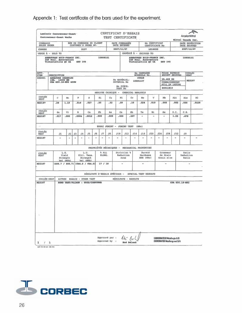
Appendix 1: Test certificate of the bars used for the experiment.
13


Appendix 2: Articles on the causes of steel embrittlement Source: Galvanizer Association of Australia Web site http://www.gaa.com.au/pdf/page15-17.pdf Factors influencing coating thickness The thickness, alloy structure and finish of galvanized coatings are influenced by: 1 Surface condition of steel 2 Composition of the steel Increasing the period of immersion in the galvanizing bath will not increase coating thickness except in the case of silicon steels, as discussed on this page. Surface condition of steel Grit blasting steel before galvanizing roughens the surface and increases its surface area, resulting in higher reactiveness to molten zinc. Greater zinc-iron alloy growth occurs during galvanizing, producing thicker coatings, though at the expense of a rougher surface and poorer appearance. Application of this method of achieving thicker coatings is generally limited by practical and economic considerations. Where increased service life or reduced maintenance is required the use of duplex galvanizing-plus-paint systems is a preferable alternative, as discussed on page 65. Composition of steel Both silicon and phosphorous contents can have major effects on the structure, appearance and properties of galvanized coatings. In extreme cases, coatings can be excessively thick, brittle and easily damaged. Silicon. As shown in the graph below, certain levels of silicon content will result in excessively thick galvanized coatings. These very thick coatings result from the increased reactivity of the steel with molten zinc, and rapid growth of zinc-iron alloy layers on the steel surface. The graph shows that excessive growth in coating thickness takes place on steels with silicon contents in the range 0.04 to 0.14%. Growth rates are less for steels containing between 0.15 and 0.22% silicon, and increase with increasing silicon levels above 0.22%. Effect of silicon content of steels on galvanized coating mass and appearance Phosphorous. The presence of phosphorous above a threshold level of approximately 0.05% produces a marked increase in reactivity of steel with molten zinc, and rapid coating growth. When present in combination with silicon, phosphorous can have a disproportionate effect, producing excessively thick galvanized coatings. Suitability of silicon/phosphorous steels for galvanizing. As a guide to the suitability of silicon and phosphorous containing steels for galvanizing, the following criteria should be applied: % Si < 0.04% And % Si + (2.5 x % P) < 0.09% Galvanized coatings on silicon steels are usually dull grey or patchy grey in colour with a rough finish, and may be brittle. Coating service life is proportional to the increased thickness and is unaffected by appearance, provided the coating is sound and continuous. In general, the thickness, adherence and appearance of galvanized coatings on silicon and phosphorous steels are outside the control the galvanizer. (See also ‘Dull grey coatings’, page 42.) Double dipping or galvanizing a second time will not increase the thickness of a galvanized coating for reasons discussed under “Coating thickness” page 13, and may adversely affect coating appearance. The terms ‘double dipping’ and ‘double-end dipping’ are sometimes confused. Double-end dipping is a method of galvanizing articles too long for the available bath by immersing one end of the work at a time, as described on page 33. Mechanical properties of galvanized steels The galvanizing process has no effect on the mechanical properties of the structural steels commonly galvanized. Strength and ductility The mechanical properties of 19 structural steels from major industrial areas of the world were investigated before and after galvanizing
in a major 4-year research project by the BNF Metals Technology Centre, UK, under the sponsorship of International Lead Zinc Research Organisation. Included were steels to Australian Standard 1511 grade A specification, and British Standard 4360 series steels. The published BNF report ‘Galvanizing of structural steels and their weldments’ ILZRO, 1975, concludes that ‘... the galvanizing process has no effect on the tensile, bend or impact properties of any of the structural steels investigated when these are galvanized in the “as manufactured” condition. Nor do even the highest strength versions exhibit hydrogen embrittlement following a typical pretreatment in inhibited HCI or H2S04. ‘Changes in mechanical properties attributable to the galvanizing process were detected only when the steel had been cold worked prior to galvanizing, but then only certain properties were affected. Thus the tensile strength, proof strength and tensile elongation of cold rolled steel were unaffected, except that the tensile elongation of 40% cold rolled steel tended to be increased by galvanizing. 1-t bends in many of the steels were embrittled by galvanizing, but galvanized 2-t and 3-t bends in all steels could be completely straightened without cracking.’ Embrittlement For steel to be in an embrittled condition after galvanizing is rare. The occurrence of embrittlement depends on a combination of factors. Under certain conditions, some steels can lose their ductile properties and become embrittled. Several types of embrittlement may occur but of these only strain-age embrittlement is aggravated by galvanizing and similar processes. The following information is given as guidance in critical applications. Susceptibility to strain-age embrittlement. Strain-age embrittlement is caused by cold working of certain steels, mainly low carbon, followed by ageing at temperatures less than 600°C, or by warm working steels below 600°C. All structural steels may become embrittled to some extent. The extent of embrittlement depends on the amount of strain, time at ageing temperature, and steel composition, particularly nitrogen content. Elements that are known to tie up nitrogen in the form of nitrides are useful in limiting the effects of strain ageing. These elements include aluminium, vanadium, titanium, niobium, and boron. Cold working such as punching of holes, shearing and bending before galvanizing may lead to embrittlement of susceptible steels. Steels in thicknesses less than 3 mm are unlikely to be significantly affected. 600 750 900 1050 1200 0 0.05 0.10 0.15 0.20 0.25 0.30 0.35 0.40 Grey GreySilicon content of steel with asrolled finish % Zinc coating mass g/m2 Partially bright Partially bright Semi lustrous Bright Grey Bright smooth Bright 1350 17 Hydrogen embrittlement. Hydrogen can be absorbed into steel during acid pickling but is expelled rapidly at galvanizing temperatures and is not a problem with components free from internal stresses. Certain steels which have been cold worked and/or stressed during pickling can be affected by hydrogen embrittlement to the extent that cracking may occur before galvanizing. The galvanizing process involves immersion in a bath of molten zinc at about 450°C. The heat treatment effect of galvanizing can accelerate the onset of strain-age embrittlement in susceptible steels which have been cold worked. No other aspect of the galvanizing process is significant. Recommendations to minimise embrittlement Where possible, use a steel with low susceptibility to strain age embrittlement. Where
cold working is necessary the following limitations must be observed: 1 Punching. The limitations specified in AS 4100 and AS/NZS 4680 on the full-size punching of holes in structural members must be observed. Material of any thickness may be punched at least 3 mm undersize and then reamed, or be drilled. Good shop practice in relation to ratios of punched hole diameter to plate thickness, and punch/die diametral clearance to plate thickness should be observed. For static loading, holes may be punched full size in material up to 5600 mm thick where Fy is material yield stress up to 360MPa. 2 Shearing. Edges of steel sections greater than 16 mm thick subject to tensile loads should be machined or machine flame cut. Edges of sections up to 16 mm thick may be cut by shearing. Sheared edges to be bent during fabrication should have stress raising features such as burrs and flame gouges removed to a depth of at least 1.5 mm. Before bending, edges should be radiused over the full arc of the bend. 3 Bending. Susceptible steels should be bent over a smooth mandrel with a minimum radius 3 times material thickness. Where possible hot work at red heat. Cold bending is unlikely to affect steels less than 3 mm thick. 4 Critical applications. It is better to avoid cold work such as punching, shearing and bending of structural steels over 6 mm thick when the item will be galvanized and subsequently subjected to critical tensile stress. If cold working cannot be avoided a practical embrittlement test in accordance with ASTM A143 should be carried out. Where the consequences of failure are severe and cold work cannot be avoided, stress relieve at a minimum of 650°C before galvanizing. Ideally, in critical applications structural steel should be hot worked above 650°C in accordance with the steelmaker’s recommendations. 5 Edge distances of holes. In accordance with Australian Standard 4100 ‘Steel structures’ minimum edge distances from the centre of any bolt to the edge of a plate or the flange of a rolled section should be used. See page 39. Fatigue strength Research and practical experience shows that the fatigue strength of the steels most commonly galvanized is not significantly affected by galvanizing. The fatigue strength of certain steels, particularly silicon killed steels may be reduced, but any reduction is small when compared with the reductions which can occur from pitting corrosion attack on ungalvanized steels, and with the effects of welds. For practical purposes, where design life is based on the fatigue strength of welds, the effects of galvanizing can be ignored. Fatigue strength is reduced by the presence of notches and weld beads, regardless of the effects of processes involving a heating cycle such as galvanizing. Rapid cooling of hot work may induce microcracking, particularly in weld zones, producing a notch effect with consequent reductions in fatigue strength. In critical applications, specifications for the galvanizing of welded steel fabrications should call for air cooling rather than water quenching after galvanizing to avoid the possibility of microcracking and reductions in fatigue strength. (…)
15


GALVANIZING R E P O R T
Corbec Inc.Éric MichaudFebruary 14, 2008
Bending of reinforcing steel after galvanizing Corbec Corporation Éric Michaud February 14, 2008


Bending of reinforcing steel bars after galvanizing
Problem statement Cold bending of reinforcing steel bars and their subsequent galvanizing create major embrittlement problems. The literature on the subject faults the exposure to hydrogen and the heat treatment that the pre-bent steel bars are subjected to during the galvanizing process. To validate this information, in-factory tests were carried out to quantify the extent as well as the severity of the phenomenon. The results of these works are showed in the document entitled: ‘’Stat of the embrittlement phenomenon of bent reinforcing bars". Last December, during a meeting between the people in charge of the MTQ's structures division and representatives of the Corbec Corporation, it was agreed that the only likely solution to the embrittlement problem was bending after galvanizing. However, the peeling phenomenon that can occur during galvanized steel bending must be controlled to avoid excessive peeling of the zinc coating.
Objective Develop a galvanizing method that allows obtaining reinforcing steel bars that can be bent after galvanizing. The bars must be able to undergo a 180o
bend, with a bending radius of 6 times the bar's diameter, without showing severe peeling of the zinc coating.
Summary The traditional galvanizing methods do not allow obtaining reinforcing steel bars that can be bent after galvanizing in a reproducible manner. The rejection rate due to severe peeling is about 60%. However, in the case of the galvanizing method specifically developed for applications where a subsequent mechanical transformation must be applied, the rejection rate due to severe peeling is lower than 5%. In fact, the method developed allows repeatedly obtaining over 95% bending with the zinc coating remaining in good condition.
19
Methodology The galvanizing tests were carried out in the factory using 15M gauge 400W grade reinforcing steel bars provided by the Armature Bois Franc (ABF) Company. The test certificate of this batch of bars is shown in appendix 1. The bending of the steel bars was carried out using a bending device put at Corbec Corporation's disposal by the Armaco Company. A photograph of this bending machine is shown in appendix 2. After galvanizing, straight steel bars were selected at random among the batch of bars. Those selected were cut in 120 centimetre (4 feet) sections to be bent at each end. Bar bending is carried out to obtain a bending diameter equivalent to 6 times the bar's diameter. In our case, where the bars are 15 mm in diameter, the bending radius of must then be 90 mm. Most bars were bent at 180o
, since it is the highest degree of bending. The zinc coating resistance after bending results were noted through bending observation as follows:
1- No peeling and/or cracks less than 1 mm in width 2- Minor peeling and/or cracks over 1 mm in width 3- Severe generalized peeling
In addition, to check the brittleness of the zinc coating, a steel brush was applied manually to the curved part of the bars.
20

85 12 2For bending
Traditional
Gal
vani
zing
met
hods
Observation (%)
0 % 20 % 40 % 60 % 80 % 100 %
16 26 59
21
Results Results for the unbending tests of the bars bent at 90o
and 180o
Table 1 Unbending of the 15m 400W reinforcing steel bars bent at 90 with a bending diameter of 6x Test Description Time in
dezinc (min) Time in acid (min)
Number of successes
Number of breaks
Breakage percentage
1 Bending before galvanizing 20 30 19 1 5 2 Bending before galvanizing 20 60 17 3 15 3 Bending before galvanizing 20 120 18 2 10 4 Bending before galvanizing 20 30 20 0 0 5 Non-galvanized steel 0 0 20 0 0 6 Non-galvanized steel 30 120 20 0 0 Table 2 Unbending of 15m 400W reinforcing steel bars bent at 180o with a bending diameter of 6x Test Description Time in
dezinc (min)
Time in acid (min)
Number of successes
Number of breaks
Breakage percentage
1 Bending before galvanizing 20 30 17 3 15 2 Bending before galvanizing 20 60 17 3 15 3 Bending before galvanizing 20 120 15 5 25 4 Bending before galvanizing 20 30 20 0 0 5 Non-galvanized steel 0 0 20 0 0 6 Non-galvanized steel 30 120 20 0 0 Note: Concentration of the dezinc and dipping tanks, respectively: 100 g HCl/l and 170 g HCl/l
Graph 1: Breakage percentage during unbending
22
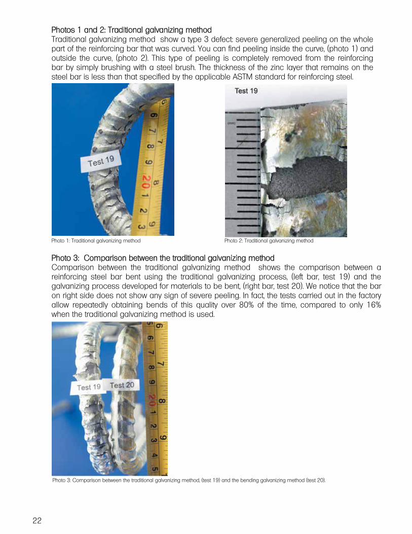
Photos 1 and 2: Traditional galvanizing method Traditional galvanizing method show a type 3 defect: severe generalized peeling on the whole part of the reinforcing bar that was curved. You can find peeling inside the curve, (photo 1) and outside the curve, (photo 2). This type of peeling is completely removed from the reinforcing bar by simply brushing with a steel brush. The thickness of the zinc layer that remains on the steel bar is less than that specified by the applicable ASTM standard for reinforcing steel. Photo 1: Traditional galvanizing method Photo 2: Traditional galvanizing method
Photo 3: Comparison between the traditional galvanizing method Comparison between the traditional galvanizing method shows the comparison between a reinforcing steel bar bent using the traditional galvanizing process, (left bar, test 19) and the galvanizing process developed for materials to be bent, (right bar, test 20). We notice that the bar on right side does not show any sign of severe peeling. In fact, the tests carried out in the factory allow repeatedly obtaining bends of this quality over 80% of the time, compared to only 16% when the traditional galvanizing method is used.
Photo 3: Comparison between the traditional galvanizing method, (test 19) and the bending galvanizing method (test 20).

Photo 4: Shows enlarged type 1 cracks. Photo 4: Type 1 cracks produced by the bending method. After bending, the bars produced using the bending galvanizing method have half the type 2 defects (minor peeling and/or cracks over 1 mm in width) than those produced by the traditional galvanizing method, or 12% vs. 26%, respectively Photo 5 shows an example of minor peeling on a reinforcing bar produced using the bending galvanizing method.
The bending of galvanized bars using automated mechanical equipment, such as the system used to carry out these tests, (photo 7), can cause peeling of small sections of the zinc coating in the internal part of the curvature radius, see photo 6. This type of highly localized peeling is caused by the friction between the chuck and the bar during bending. In these cases, peeling does not embrittle the zinc coating of adjacent surfaces and generally leaves a layer of zinc of over 87 um. Peeling produced by the bending system
Photo 5: Type 2 defect example, (minor peeling and/or cracks over 1 mm in width)
23

Considering that the main embrittlement issues are eliminated using the bending after galvanizing process, the few peeling problems that have affected approximately 2% of the bends carried out on the galvanized bars using the bending method are of minor importance. Measurements carried out show that the surface of the bar after peeling of the external zinc layer has a thickness of approximately 30 to 50 um, combined with the galvanic protection of the zinc present around the peeled surface; protection against corrosion remains and is active. All bends were carried out with bars whose temperature during bending varied between 10 and 20oC. However, additional tests were carried out to check the behaviour of the zinc coating on bars that could eventually be stored in winter conditions. A sample of 15 bars bent at 180o
not showing any type 1 defects was subjected to a temperature of -20oC during 21 hours: graph 2. As soon as they were taken out of the freezer, the bars were immediately bent. All 15 bends carried out on the samples exposed to cold only showed type 1 cracks. This was therefore comparable to the cracks observed with the bends carried out under ambient conditions. Therefore, the temperature of the bars during bending does not appear to be a critical factor that could negatively affect the zinc coating's behaviour during bending. Graph 2: Storage temperature of the reinforcing steel bars before the cold bending test.
24
Conclusion This study was aimed at developing a galvanizing method that allowed obtaining reinforcing steel bars that can be bent after galvanizing, while keeping the zinc coating in good condition. The tests carried out show that by controlling certain key parameters, it is possible to repeatedly obtain galvanized reinforcing steel bars that will have the characteristics needed to sustain a 180o
bend, with a bending radius of 6 times the bar's diameter, without major peeling of the zinc coating.
Discussion The experiments made in-factory during the last month of January show that the embrittlement problems can affect 15% of the reinforcing steel bars bent before galvanizing when they are subjected to unbending tests 1, in some cases the embrittlement affects over 30% of the bars subjected to the same tests. While straight galvanized bars bent after galvanizing behave as non-galvanized steel bars when they are subjected to unbending tests, with near-zero rupture rates. Appendix 3 shows unbending examples. Therefore, given that the peeling problems can be limited by adequately controlling certain parameters during the galvanizing process, the bending of reinforcing steel bars after galvanizing proves to be a suitable way to obtain non-embrittled reinforcing steel bars. Note 1: According to the results of tests carried out by Corbec in January 2008: « Study of the bent reinforcing steel bars embrittlement phenomenon ».
25
Appendix 1: Test certificate of the bars used for the experiment.
26
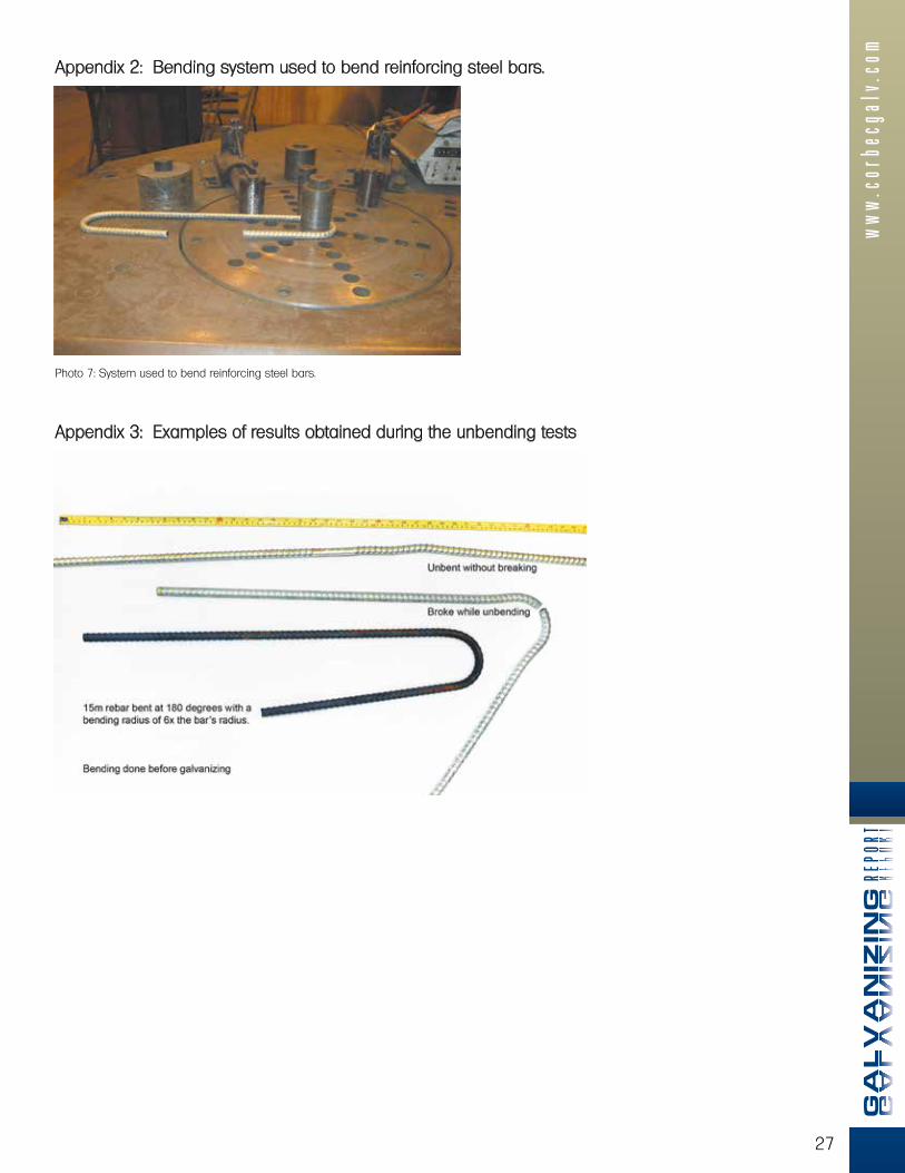
Appendix 2: Bending system used to bend reinforcing steel bars. Photo 7: System used to bend reinforcing steel bars.
Appendix 3: Examples of results obtained during the unbending tests
27


GALVANIZING R E P O R T
Corbec Inc.Éric MichaudAugust 19, 2008
29
Reinforcing steel bent after galvanizing(Substantiating document for rebar fabricators)
In the note published on April 21st, the MTQ recommends using reinforcing steel bent after galvanizing. This measure is intended to eliminate the problem of reinforcing steel embrittlement. Since some bars can show signs of peeling, the MTQ tolerates that a surface equivalent to the bar section’s surface be peeled.
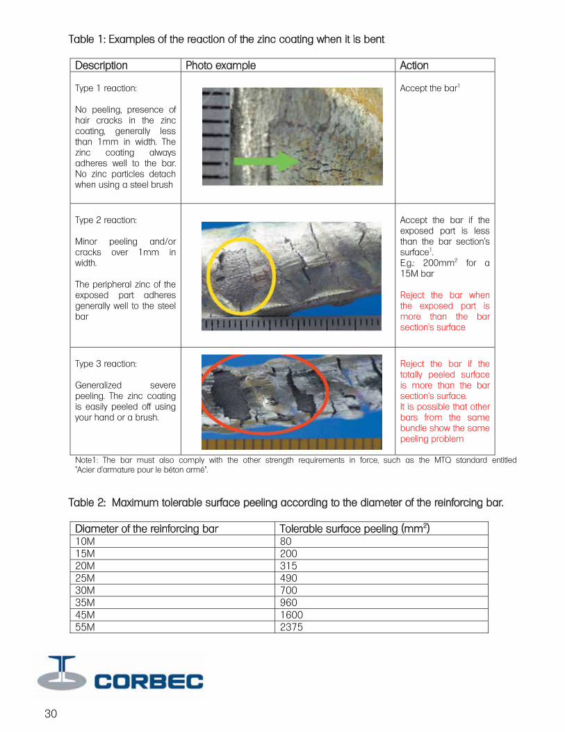
Table 1 shows the main situations encountered when a galvanized steel bar is bent.
Table 2 gives the maximum surface peeling tolerated according to the diameter of the reinforcing bar.
30
Table 1: Examples of the reaction of the zinc coating when it is bent Description Photo example Action Type 1 reaction: No peeling, presence of hair cracks in the zinc coating, generally less than 1mm in width. The zinc coating always adheres well to the bar. No zinc particles detach when using a steel brush
Accept the bar1
Type 2 reaction: Minor peeling and/or cracks over 1mm in width. The peripheral zinc of the exposed part adheres generally well to the steel bar
Accept the bar if the exposed part is less than the bar section's surface1. E.g.: 200mm2 for a 15M bar Reject the bar when the exposed part is more than the bar section's surface
Type 3 reaction: Generalized severe peeling. The zinc coating is easily peeled off using your hand or a brush.
Reject the bar if the totally peeled surface is more than the bar section's surface. It is possible that other bars from the same bundle show the same peeling problem
Note1: The bar must also comply with the other strength requirements in force, such as the MTQ standard entitled "Acier d’armature pour le béton armé".
Table 2: Maximum tolerable surface peeling according to the diameter of the reinforcing bar. Diameter of the reinforcing bar Tolerable surface peeling (mm2) 10M 80 15M 200 20M 315 25M 490 30M 700 35M 960 45M 1600 55M 2375
31

32
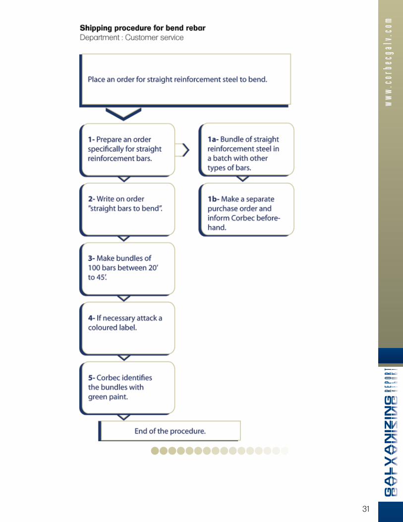
Shipping procedure for bend rebar Department : Customer service
Number Activity title Activity details Person in charge
Documents needed
Records
1 Create a delivery slip.
The client must prepare an order only for a batch of reinforcement steel to bend.
Client Delivery slip
1a Create a delivery slip.
One or several bundles of straight reinforcing steel to bend are sent with other types of bars.
Client Delivery slip
1b Create a delivery slip.
The client must prepare a separate, clearly identified delivery slip for the bundles to bend.
Client Delivery slip
2 Create a delivery slip.
The customer must clearly write on his slip "Straight reinforcing steel bars to bend"
Client Delivery slip
3
Packaging The 15m and 20m reinforcement steel bars must be packaged in bundles of 100 bars.
Client N/A
4
Packaging The reinforcement steel bars to bend must have a coloured label if they are sent with other types of bars on the same truck.
Client N/A
5
Packaging and shipping
After galvanizing, Corbec will identify the bundles of straight reinforcement steel to bend with green paint at each end and in the middle.
Corbec N/A
6 Table for # bars by length
10M X 150 = 1413KG 15M X 100 = 1884KG 20M X 100 = 2826KG 25M X 50 = 2355KG 30M X 50 = 3297KG 35M X 25 = 4710KG 45M X 25 = 3532KG 55M X 25 = 5887KG
This procedure was created according to the new guidelines established by the MTQ for the bending of reinforcement steel bars after galvanizing. Note that the process will be in force as of Monday, May 5, 2008.
GALVANIZING R E P O R T
33
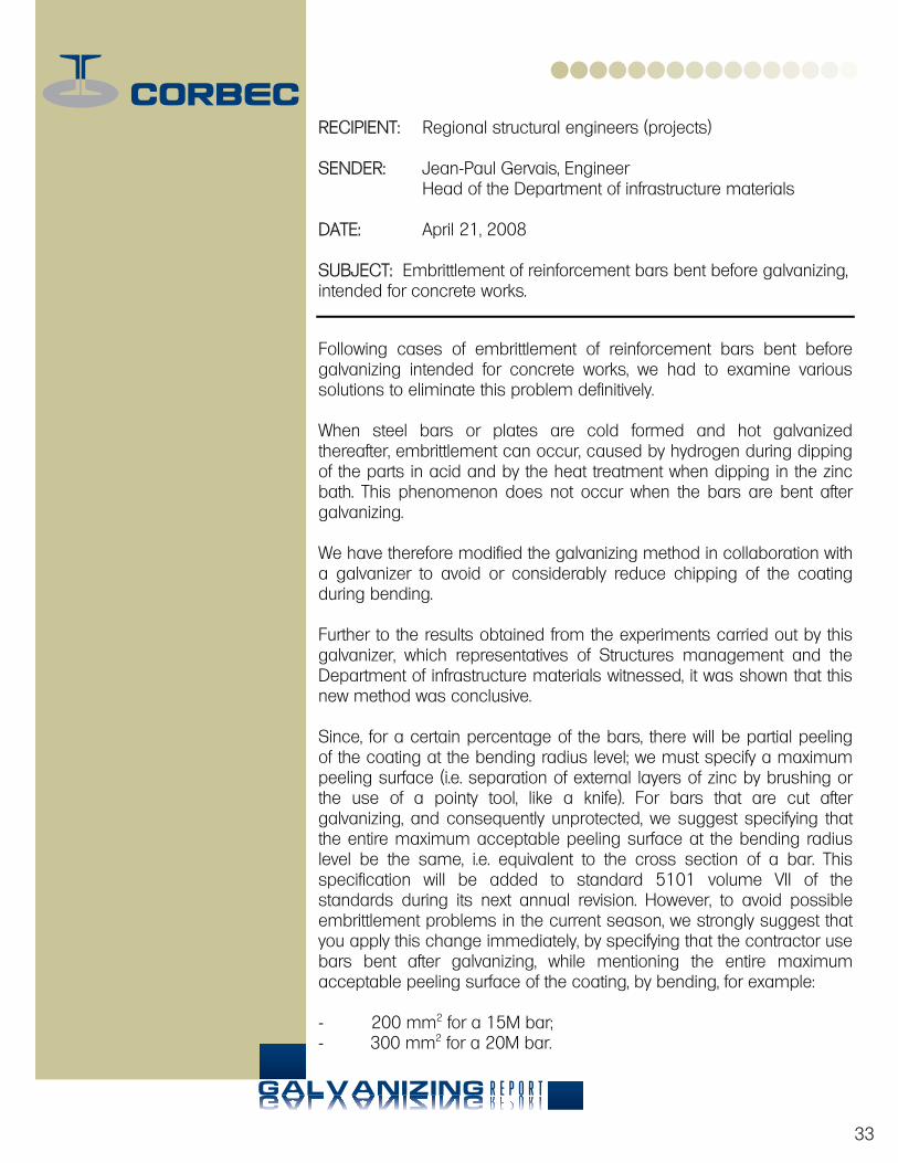
RECIPIENT: Regional structural engineers (projects) SENDER: Jean-Paul Gervais, Engineer Head of the Department of infrastructure materials DATE: April 21, 2008 SUBJECT: Embrittlement of reinforcement bars bent before galvanizing, intended for concrete works.
Following cases of embrittlement of reinforcement bars bent before galvanizing intended for concrete works, we had to examine various solutions to eliminate this problem definitively. When steel bars or plates are cold formed and hot galvanized thereafter, embrittlement can occur, caused by hydrogen during dipping of the parts in acid and by the heat treatment when dipping in the zinc bath. This phenomenon does not occur when the bars are bent after galvanizing. We have therefore modified the galvanizing method in collaboration with a galvanizer to avoid or considerably reduce chipping of the coating during bending. Further to the results obtained from the experiments carried out by this galvanizer, which representatives of Structures management and the Department of infrastructure materials witnessed, it was shown that this new method was conclusive. Since, for a certain percentage of the bars, there will be partial peeling of the coating at the bending radius level; we must specify a maximum peeling surface (i.e. separation of external layers of zinc by brushing or the use of a pointy tool, like a knife). For bars that are cut after galvanizing, and consequently unprotected, we suggest specifying that the entire maximum acceptable peeling surface at the bending radius level be the same, i.e. equivalent to the cross section of a bar. This specification will be added to standard 5101 volume VII of the standards during its next annual revision. However, to avoid possible embrittlement problems in the current season, we strongly suggest that you apply this change immediately, by specifying that the contractor use bars bent after galvanizing, while mentioning the entire maximum acceptable peeling surface of the coating, by bending, for example: - 200 mm2 for a 15M bar; - 300 mm2 for a 20M bar.
34
These modifications made under the terms of a contract binding the MTQ and a contractor have no financial impact. We must nonetheless mention that the subcontractor in charge of manufacturing the reinforcing steel will no longer need to redo his reinforcing steel packages after galvanizing, which represents in itself a considerable gain for him. Please forward this letter to your designers and supervisors, whether they are employed by the Ministry or an agent, so that they may implement this as soon as possible. We remain at your disposal and thank you for your collaboration. __________________________________________ Jean-Paul Gervais, Engineer Head of the Department of infrastructure materials 2700, rue Einstein Québec, QC. cc. Guy Richard, Engineer M. Sc. A. Manager, Structure management Claude Tremblay, Engineer Manager, Pavement laboratory management Gérard Desgagné, Engineer M. Sc. Head of the Design department Denis Bérubé, Engineer Maintenance department Donald Villeneuve, Engineer. Department of infrastructure materials Regional managers


B E N D I N G S T E E L A F T E RB E N D I N G S T E E L A F T E RH O T D I P GALVANIZATING
GALVANIZING EXCELLENCE SINCE...1965
C o r b e c C o r p o r a t i o n I n c .
www.
corb
ecga
lv.c
om
9960, Côte-de-Liesse, suite 201Lachine, QcH8T 1A1
Phone : 514-364-4000 Fax : 514-365-9222 Toll Free : 1 800 463-8313
R E P O R T


