+ All Categories
Home > Documents > A 0671-0672 F09-23 cENG - th.misumi-ec.com · PDF fileWeight per Meter (kg) A B C W P L F T J...

A 0671-0672 F09-23 cENG - th.misumi-ec.com · PDF fileWeight per Meter (kg) A B C W P L F T J...

Date post: 16-Mar-2018
Category:
Upload: truongque
View: 217 times
Download: 1 times
Share this document with a friend
1
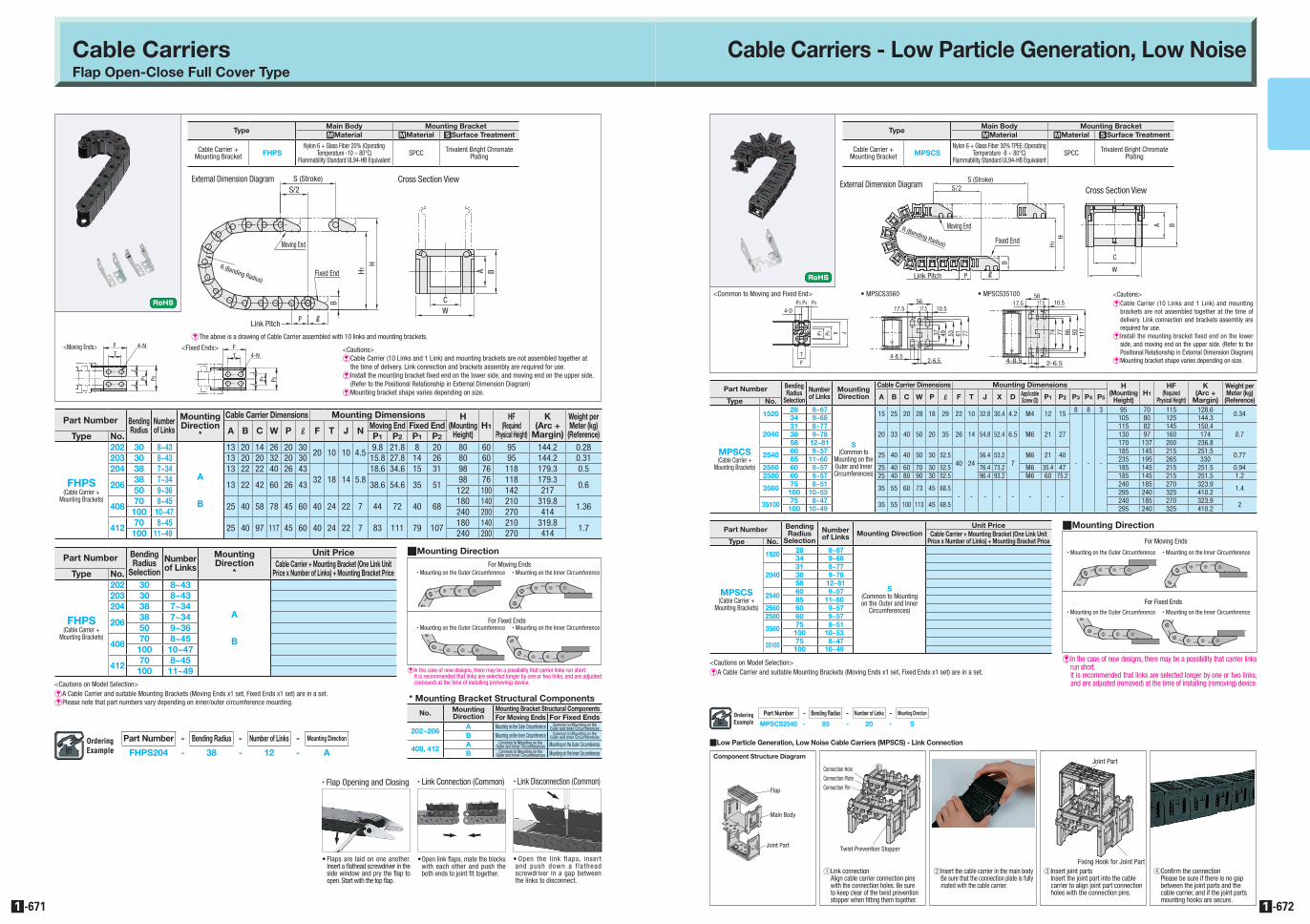
Cable Carriers - Low Particle Generation, Low Noise Cable Carriers Flap Open-Close Full Cover Type Part Number - Bending Radius - Number of Links - Mounting Direction MPSCS2540 - 85 - 20 - S Part Number - Bending Radius - Number of Links - Mounting Direction FHPS204 - 38 - 12 - A -671 1 -672 1 L P S/2 B H1 H C A B W S (Stroke) R (Bending Radius) Moving End Fixed End Link Pitch EThe above is a drawing of Cable Carrier assembled with 10 links and mounting brackets. <Cautions> ECable Carrier (10 Links and 1 Link) and mounting brackets are not assembled together at the time of delivery. Link connection and brackets assembly are required for use. EInstall the mounting bracket fixed end on the lower side, and moving end on the upper side. (Refer to the Positional Relationship in External Dimension Diagram) EMounting bracket shape varies depending on size. <Moving Ends> <Fixed Ends> F T P2 J J P1 4-N F T P2 J J P1 4-N External Dimension Diagram Cross Section View S (Stroke) S/2 H1 H R (Bending Radius) Link Pitch P L B B A W C Moving End Fixed End <Cautions> ECable Carrier (10 Links and 1 Link) and mounting brackets are not assembled together at the time of delivery. Link connection and brackets assembly are required for use. EInstall the mounting bracket fixed end on the lower side, and moving end on the upper side. (Refer to the Positional Relationship in External Dimension Diagram) EMounting bracket shape varies depending on size. <Common to Moving and Fixed End> • MPSCS3560 • MPSCS35100 4-8.5 2-6.5 77 61 53 49 37 17.5 56 10.5 17.5 4-8.5 2-6.5 56 117 10.5 17.5 17.5 93 86 77 74 P1 P2 X J T F P5 P4 P3 4-D External Dimension Diagram Cross Section View Type Main Body Mounting Bracket MMaterial MMaterial SSurface Treatment Cable Carrier + Mounting Bracket FHPS Nylon 6 + Glass Fiber 20% (Operating Temperature -10 ~ 80°C) Flammability Standard UL94-HB Equivalent SPCC Trivalent Bright Chromate Plating Part Number Bending Radius Number of Links Mounting Direction * Cable Carrier Dimensions Mounting Dimensions H (Mounting Height) H1 HF (Required Physical Height) K (Arc + Margin) Weight per Meter (kg) (Reference) A B C W P L F T J N Moving End Fixed End Type No. P1 P2 P1 P2 FHPS (Cable Carrier + Mounting Brackets) 202 30 8~43 A B 13 20 14 26 20 30 20 10 10 4.5 9.8 21.8 8 20 80 60 95 144.2 0.28 203 30 8~43 13 20 20 32 20 30 15.8 27.8 14 26 80 60 95 144.2 0.31 204 38 7~34 13 22 22 40 26 43 32 18 14 5.8 18.6 34.6 15 31 98 76 118 179.3 0.5 206 38 7~34 13 22 42 60 26 43 38.6 54.6 35 51 98 76 118 179.3 0.6 50 9~36 122 100 142 217 408 70 8~45 25 40 58 78 45 60 40 24 22 7 44 72 40 68 180 140 210 319.8 1.36 100 10~47 240 200 270 414 412 70 8~45 25 40 97 117 45 60 40 24 22 7 83 111 79 107 180 140 210 319.8 1.7 100 11~49 240 200 270 414 Part Number Bending Radius Selection Number of Links Mounting Direction * Unit Price Cable Carrier + Mounting Bracket (One Link Unit Price x Number of Links) + Mounting Bracket Price Type No. FHPS (Cable Carrier + Mounting Brackets) 202 30 8~43 A B 203 30 8~43 204 38 7~34 206 38 7~34 50 9~36 408 70 8~45 100 10~47 412 70 8~45 100 11~49 Type Main Body Mounting Bracket MMaterial MMaterial SSurface Treatment Cable Carrier + Mounting Bracket MPSCS Nylon 6 + Glass Fiber 30% TPEE (Operating Temperature -8 ~ 80°C) Flammability Standard UL94-HB Equivalent SPCC Trivalent Bright Chromate Plating Part Number Bending Radius Selection Number of Links Mounting Direction Cable Carrier Dimensions Mounting Dimensions H (Mounting Height) H1 HF (Required Physical Height) K (Arc + Margin) Weight per Meter (kg) (Reference) A B C W P L F T J X D Applicable Screw (D) P1 P2 P3 P4 P5 Type No. MPSCS (Cable Carrier + Mounting Brackets) 1520 28 8~67 S (Common to Mounting on the Outer and Inner Circumferences) 15 25 20 28 18 29 22 10 32.8 30.4 4.2 M4 12 15 8 8 3 95 70 115 128.6 0.34 34 9~68 - - - 105 80 125 144.3 2040 31 8~77 20 33 40 50 20 35 26 14 54.8 52.4 6.5 M6 21 27 115 82 145 150.4 0.7 38 9~78 130 97 160 174 58 12~81 170 137 200 236.8 2540 60 9~57 25 40 40 50 30 52.5 40 24 56.4 53.2 7 M6 21 40 185 145 215 251.5 0.77 85 11~60 235 195 265 330 2560 60 9~57 25 40 60 70 30 52.5 76.4 73.2 M6 35.4 47 185 145 215 251.5 0.94 2580 60 9~57 25 40 80 90 30 52.5 96.4 93.2 M6 60 75.2 185 145 215 251.5 1.2 3560 75 8~51 35 55 60 73 45 68.5 - - - - - - - - 240 185 270 323.9 1.4 100 10~53 295 240 325 410.2 35100 75 8~47 35 55 100 113 45 68.5 240 185 270 323.9 2 100 10~49 295 240 325 410.2 Part Number Bending Radius Selection Number of Links Mounting Direction Unit Price Cable Carrier + Mounting Bracket (One Link Unit Price x Number of Links) + Mounting Bracket Price Type No. MPSCS (Cable Carrier + Mounting Brackets) 1520 28 8~67 S (Common to Mounting on the Outer and Inner Circumferences) 34 9~68 2040 31 8~77 38 9~78 58 12~81 2540 60 9~57 85 11~60 2560 60 9~57 2580 60 9~57 3560 75 8~51 100 10~53 35100 75 8~47 100 10~49 <Cautions on Model Selection> EA Cable Carrier and suitable Mounting Brackets (Moving Ends x1 set, Fixed Ends x1 set) are in a set. EPlease note that part numbers vary depending on inner/outer circumference mounting. Link Connection (Common) Open link flaps, mate the blocks with each other and push the both ends to joint fit together. Link Disconnection (Common) Open the link flaps, insert and push down a flathead screwdriver in a gap between the links to disconnect. Flaps are laid on one another. Insert a flathead screwdriver in the side window and pry the flap to open. Start with the top flap. Flap Opening and Closing QMounting Direction * Mounting Bracket Structural Components No. Mounting Direction Mounting Bracket Structural Components For Moving Ends For Fixed Ends 202~206 A Mounting on the Outer Circumference Common to Mounting on the Outer and Inner Circumferences B Mounting on the Inner Circumference Common to Mounting on the Outer and Inner Circumferences 408, 412 A Common to Mounting on the Outer and Inner Circumferences Mounting on the Outer Circumference B Common to Mounting on the Outer and Inner Circumferences Mounting on the Inner Circumference EIn the case of new designs, there may be a possibility that carrier links run short. It is recommended that links are selected longer by one or two links, and are adjusted (removed) at the time of installing (removing) device. <Cautions on Model Selection> EA Cable Carrier and suitable Mounting Brackets (Moving Ends x1 set, Fixed Ends x1 set) are in a set. QLow Particle Generation, Low Noise Cable Carriers (MPSCS) - Link Connection Component Structure Diagram Flap Main Body Joint Part 1Link connection Align cable carrier connection pins with the connection holes. Be sure to keep clear of the twist prevention stopper when fitting them together. 2 Insert the cable carrier in the main body Be sure that the connection plate is fully mated with the cable carrier. 3Insert joint parts Insert the joint part into the cable carrier to align joint part connection holes with the connection pins. 4Confirm the connection Please be sure if there is no gap between the joint parts and the cable carrier, and if the joint parts mounting hooks are secure. Connection Pin Twist Prevention Stopper Connection Hole Connection Plate Joint Part Fixing Hook for Joint Part QMounting Direction EIn the case of new designs, there may be a possibility that carrier links run short. It is recommended that links are selected longer by one or two links, and are adjusted (removed) at the time of installing (removing) device. For Moving Ends Mounting on the Outer Circumference Mounting on the Inner Circumference For Fixed Ends Mounting on the Outer Circumference Mounting on the Inner Circumference For Moving Ends Mounting on the Outer Circumference Mounting on the Inner Circumference For Fixed Ends Mounting on the Outer Circumference Mounting on the Inner Circumference
Transcript

Cable Carriers - Low Particle Generation, Low NoiseCable CarriersFlap Open-Close Full Cover Type

Part Number - Bending Radius - Number of Links - Mounting Direction

MPSCS2540 - 85 - 20 - S

Part Number - Bending Radius - Number of Links - Mounting Direction

FHPS204 - 38 - 12 - A

-6711 -6721

LP

S/2

B

H1H

C

A B

W

S (Stroke)

R (Bending Radius)

Moving End

Fixed End

Link Pitch

EThe above is a drawing of Cable Carrier assembled with 10 links and mounting brackets.

<Cautions>E Cable Carrier (10 Links and 1 Link) and mounting brackets are not assembled together at

the time of delivery. Link connection and brackets assembly are required for use.E Install the mounting bracket fixed end on the lower side, and moving end on the upper side.

(Refer to the Positional Relationship in External Dimension Diagram)E Mounting bracket shape varies depending on size.

<Moving Ends> <Fixed Ends>FT

P2

JJ

P 1

4-N FT

P2

JJ

P 1

4-N

External Dimension Diagram Cross Section View S (Stroke)S/2

H1H

R (Bending Radius)

Link Pitch P L

B

BA

W

C

Moving End

Fixed End

<Cautions>E Cable Carrier (10 Links and 1 Link) and mounting

brackets are not assembled together at the time of delivery. Link connection and brackets assembly are required for use.

E Install the mounting bracket fixed end on the lower side, and moving end on the upper side. (Refer to the Positional Relationship in External Dimension Diagram)

E Mounting bracket shape varies depending on size.

<Common to Moving and Fixed End> • MPSCS3560 • MPSCS35100

4-8.52-6.5

7761534937

17.556

10.517.5

4-8.5 2-6.5

56

117

10.517.517.5

93867774P1 P2 X J

TF

P5P4P3

4-D

External Dimension DiagramCross Section View

A_0671-0672_F09-23_cENGA_0671-0672_F09-23_cENG cENG 2nd

TypeMain Body Mounting BracketMMaterial MMaterial SSurface Treatment

Cable Carrier + Mounting Bracket FHPS

Nylon 6 + Glass Fiber 20% (Operating Temperature -10 ~ 80°C)

Flammability Standard UL94-HB EquivalentSPCC Trivalent Bright Chromate

Plating

Part Number Bending Radius

Number of Links

Mounting Direction

*

Cable Carrier Dimensions Mounting Dimensions H (Mounting

Height)H1

HF(Required

Physical Height)

K (Arc +

Margin)

Weight per Meter (kg)

(Reference)A B C W P L F T J N Moving End Fixed EndType No. P1 P2 P1 P2

FHPS (Cable Carrier +

Mounting Brackets)

202 30 8~43

A

B

13 20 14 26 20 3020 10 10 4.5

9.8 21.8 8 20 80 60 95 144.2 0.28203 30 8~43 13 20 20 32 20 30 15.8 27.8 14 26 80 60 95 144.2 0.31204 38 7~34 13 22 22 40 26 43

32 18 14 5.818.6 34.6 15 31 98 76 118 179.3 0.5

20638 7~34

13 22 42 60 26 43 38.6 54.6 35 5198 76 118 179.3

0.650 9~36 122 100 142 217

40870 8~45

25 40 58 78 45 60 40 24 22 7 44 72 40 68180 140 210 319.8

1.36100 10~47 240 200 270 414

412 70 8~4525 40 97 117 45 60 40 24 22 7 83 111 79 107

180 140 210 319.81.7

100 11~49 240 200 270 414

Part Number Bending Radius

Selection

Number of Links

Mounting Direction

*

Unit PriceCable Carrier + Mounting Bracket (One Link Unit

Price x Number of Links) + Mounting Bracket PriceType No.

FHPS (Cable Carrier +

Mounting Brackets)

202 30 8~43

A

B

203 30 8~43204 38 7~34

20638 7~3450 9~36

40870 8~45

100 10~47

412 70 8~45100 11~49

TypeMain Body Mounting BracketMMaterial MMaterial SSurface Treatment

Cable Carrier + Mounting Bracket MPSCS

Nylon 6 + Glass Fiber 30% TPEE (Operating Temperature -8 ~ 80°C)

Flammability Standard UL94-HB EquivalentSPCC Trivalent Bright Chromate

Plating

Part Number Bending Radius

Selection

Number of Links

Mounting Direction

Cable Carrier Dimensions Mounting Dimensions H (Mounting

Height)H1

HF(Required

Physical Height)

K(Arc +

Margin)

Weight per Meter (kg)

(Reference)A B C W P L F T J X D Applicable Screw (D) P1 P2 P3 P4 P5Type No.

MPSCS (Cable Carrier +

Mounting Brackets)

1520 28 8~67

S (Common to

Mounting on the Outer and Inner Circumferences)

15 25 20 28 18 29 22 10 32.8 30.4 4.2 M4 12 158 8 3 95 70 115 128.6

0.3434 9~68

- - -

105 80 125 144.3

204031 8~77

20 33 40 50 20 35 26 14 54.8 52.4 6.5 M6 21 27115 82 145 150.4

0.738 9~78 130 97 160 17458 12~81 170 137 200 236.8

2540 60 9~5725 40 40 50 30 52.5

40 2456.4 53.2

7M6 21 40

185 145 215 251.50.7785 11~60 235 195 265 330

2560 60 9~57 25 40 60 70 30 52.5 76.4 73.2 M6 35.4 47 185 145 215 251.5 0.942580 60 9~57 25 40 80 90 30 52.5 96.4 93.2 M6 60 75.2 185 145 215 251.5 1.2

3560 75 8~5135 55 60 73 45 68.5

- - - - - - - -

240 185 270 323.91.4100 10~53 295 240 325 410.2

35100 75 8~47 35 55 100 113 45 68.5 240 185 270 323.9 2100 10~49 295 240 325 410.2

Part Number Bending Radius

Selection

Number of Links Mounting Direction

Unit PriceCable Carrier + Mounting Bracket (One Link Unit

Price x Number of Links) + Mounting Bracket PriceType No.

MPSCS (Cable Carrier +

Mounting Brackets)

1520 28 8~67

S (Common to Mounting on the Outer and Inner

Circumferences)

34 9~68

204031 8~7738 9~7858 12~81

2540 60 9~5785 11~60

2560 60 9~572580 60 9~57

3560 75 8~51100 10~53

35100 75 8~47100 10~49

<Cautions on Model Selection>E A Cable Carrier and suitable Mounting Brackets (Moving Ends x1 set, Fixed Ends x1 set) are in a set.E Please note that part numbers vary depending on inner/outer circumference mounting.

• Link Connection (Common)

• Open link flaps, mate the blocks with each other and push the both ends to joint fit together.

• Link Disconnection (Common)

• Open the link flaps, insert and push down a f la thead screwdriver in a gap between the links to disconnect.

• Flaps are laid on one another. Insert a flathead screwdriver in the side window and pry the flap to open. Start with the top flap.

• Flap Opening and Closing

QMounting Direction

* Mounting Bracket Structural Components

No. Mounting Direction

Mounting Bracket Structural ComponentsFor Moving Ends For Fixed Ends

202~206A Mounting on the Outer Circumference Common to Mounting on the

Outer and Inner Circumferences

B Mounting on the Inner Circumference Common to Mounting on the Outer and Inner Circumferences

408, 412A Common to Mounting on the

Outer and Inner Circumferences Mounting on the Outer Circumference

B Common to Mounting on the Outer and Inner Circumferences Mounting on the Inner Circumference

E In the case of new designs, there may be a possibility that carrier links run short. It is recommended that links are selected longer by one or two links, and are adjusted (removed) at the time of installing (removing) device.

<Cautions on Model Selection>E A Cable Carrier and suitable Mounting Brackets (Moving Ends x1 set, Fixed Ends x1 set) are in a set.

QLow Particle Generation, Low Noise Cable Carriers (MPSCS) - Link Connection

Component Structure Diagram

Flap

Main Body

Joint Part

1Link connectionAlign cable carrier connection pins with the connection holes. Be sure to keep clear of the twist prevention stopper when fitting them together.

2�Insert the cable carrier in the main bodyBe sure that the connection plate is fully mated with the cable carrier.

3Insert joint partsInsert the joint part into the cable carrier to align joint part connection holes with the connection pins.

4Confirm the connectionPlease be sure if there is no gap between the joint parts and the cable carrier, and if the joint parts mounting hooks are secure.

Connection Pin

Twist Prevention Stopper

Connection HoleConnection Plate

Joint Part

Fixing Hook for Joint Part

QMounting Direction

E In the case of new designs, there may be a possibility that carrier links run short. It is recommended that links are selected longer by one or two links, and are adjusted (removed) at the time of installing (removing) device.

For Moving Ends• Mounting on the Outer Circumference • Mounting on the Inner Circumference

For Fixed Ends• Mounting on the Outer Circumference • Mounting on the Inner Circumference

For Moving Ends• Mounting on the Outer Circumference • Mounting on the Inner Circumference

For Fixed Ends• Mounting on the Outer Circumference • Mounting on the Inner Circumference

Recommended