A 13-/ Map of the Actin-Scruin Filament from the Limulus Acrosomal Process C a m O w e n a n d D a v i d DeRos ie r
Rosenstiel Basic Medical Sciences Research Center; Brandeis University, Waltham, Massachusetts 02254
Abstract. We have determined the structure of the ac- tin-scruin filament to 13-/k resolution using a combi- nation of low-dose EM and image analysis. The three- dimensional map reveals four actin-actin contacts: two within each strand and two between strands. The con- formation of the actin subunit is different from that in the Holmes et al. (1990) model as refined by Lorenz et al. (1993). In particular, subdomain II is tilted in a similar way to that seen by Orlova and Egelman
(1993) in F-Mg2÷-ADP actin filaments in the absence of Ca 2÷. Scruin appears to consist of two domains of approximately equal volume. Each scruin subunit cross-links the two strands in the actin filament. Do- main I of scruin contacts subdomain I of actin and makes a second contact at the junction of subdomains In and IV. Domain II of scruin contacts actin at sub- domains I and II of a neighboring actin subunit. The two scruin domains thus bind differently to actin.
TIS is a structural protein involved in cell motility and shape. The utility of actin lies in its abili~ to bind different actin binding proteins and generate
different functional assemblies. Examples include the con- tractile apparatus of muscle (Huxley, 1969), microvillar bundles of intestinal epithelial cells (Maroux et al., 1988; Burgess, 1987), stereocilia of the inner ear (Flock and Cheung, 1977; DeRosier et al., 1980), the acrosomal pro- cess of Limulus sperm (Tilney, 1975), bundles within the filopodia of Dictyostelium (Demma et al., 1990; Dhar- mawardhane et al., 1991; Owen et al., 1992), and the eryth- rocyte cytoskeleton (Branton et al., 1981). Recent findings suggest that actin structures can also provide indirect control of cellular processes. For instance, EF-la, which is an im- portant component of protein synthesis, is also an actin bun- dling protein that is associated with locomotion in Dic- tyostelium (Yang et al., 1990; Dharmawardhane et al., 1991).
Knowledge of the high resolution structure is necessary for understanding how actin can be involved in different structures and interactions. Much has been learned over the past 15 yr by EM and image analysis (Moore et al., 1970; Vibert and Craig, 1982; Bullitt et al., 1988; Milligan et al., 1990), but the recent atomic structure of an actin:DNase I co-crystal (Kabsch et al., 1990) is facilitating the interpreta- tion of much of the existing data (Holmes et al., 1990; Lorenz et al., 1993; Rayment et al., 1993; Schroder et al., 1993). It allows us to consider how the subdomains of actin interact with the various actin binding proteins. Are the sub- domains locked or free to move, as suggested by normal mode analysis of G-actin (Tirion and ben-Avraham, 1993)? How does the tertiary conformation change with different ac- tin binding proteins?
EM is ideally suited for looking at actin in different assem- blies. Actin filaments are helical structures, and by the nature of a helix provide three-dimensional information from a sin- gle view (DeRosier and Moore, 1970). A resolution of 25/~ radially by 45/~ axially has been sufficient to make detailed observations of the actin filament bound with myosin subfragment-1 (S1) and tropomyosin (Milligan et al., 1987, 1990); thin filaments plus invertebrate myosin S1 with and without regulatory light chain (Vibert and Craig, 1982); and F-actin in which evidence has been found for a conforma- tional change dependent on the nucleotide (Orlova and Egel- man, 1992) or the divalent cation (Mg 2÷ vs Ca 2+) (Orlova and Egelman, 1993).
We have studied F-actin filaments bound with the ll0-kD Limulus acrosomal process protein scruin (Tilney, 1975; Bullitt et al., 1988). The acrosomal process is a 60-#m-long actin bundle composed of ~o100 hexagonally packed actin filaments, wound into a supercoil about the base of the nu- cleus. Upon stimulation, the supercoil is released, and the bundle rapidly uncoils and extends through the nucleus and out the anterior end of the sperm to penetrate the egg. Re- cently, the gene for scruin has been cloned and sequenced (M. Way and P. Matsudaira, personal communication). They found it is a 103-kD protein containing two domains that have arisen through gene duplication. Scruin is related to the protein kelch which has one rather than two domains. Kelch is found in the ring canal between the nurse cell and the de- veloping oocyte in Drosophila (Xue and Cooley, 1993).
Our goal in this work was to extend the resolution of previ- ous work to better resolve the actin structure and conforma- tion and better identify its interaction with scruin. We car- ried this out by collecting Fourier data for layer lines beyond the resolution at which reflections were obvious above the
background. We then averaged many such data sets to im- prove the signal/noise ratio and calculated a 13-,~ map. We fit the atomic model for actin to our map, in order to (a) define the boundary between actin and scruin, (b) determine the contact sites between actin and scruin subunits, and (c) make a detailed comparison of the actin monomer in this ac- tin/scruin structure with that in other F-actin containing structures and with the monomer in an actin/DNase I structure.
Materials and Methods
Preparation of Acrosomal Processes Sperm from Limulus polyphemus were collected as described previously (Tilney, 1975). Sperm were washed in collecting media (423 mM NaC1, 10 mM KCI, 2 mM MgC12, 5 mM NaPO4, pH 8.0), then resuspended in TPM (1% Triton X-100 [Sigma Immunochemicals, St. Louis, MO], 5 mM NaPO4, 2 mM MgC12, 0.1 mM EDTA, 0.2 mM ATE pH 8.0), which in- duces the false discharge. Acrosomal processes were sheared off by sucking repeatedly up and down a Pasteur pipette. Sperm nuclei and attached flagel- lar axonemes and acrosomal caps were removed by centrifugation for 5 min at 750 g. The supernate contains primarily acrosomal processes, with an occasional flagellar axoneme or nucleus, as judged by light microscopy. Acrosomal processes were centrifuged for 10 min at 10,000 g and the pellet resuspended in F-actin buffer (2 mM MgC12, 10 mM KCI, 5 mM NaPO4, 0.2 mM ATE pH 7.5). The acrosomal processes were then centrifuged and resuspended in a small quantity of G-actin buffer (2 mM Tris, 0.2 mM CaCl2, 0.5 ram DTT, 0.2 mM ATE 1 /zg/ml leupeptin, pH 8.2) and dia- lyzed for several hours against G-actin buffer that included 0.1 mM PMSE G-actin buffer caused bundles to dissociate into single actin-scrniu fila- ments, as judged by EM.
SDS Gel Electrophoresis Undissociated bundles were removed from the dissociated bundle suspen- sion by centrifuging for 3 min in a desktop microfuge. Filaments were ana- lyzed by discontinuous SDS-PAGE with a 5% stacking gel and a 12% resolving gel (Laemmli, 1970).
Microscopy Actin-scruin filaments were applied to 400-mesh carbon-coated copper grids, washed with G-actin buffer and negatively stained with 1% uranyl acetate. Specimens were examined at ambient temperature and pho- tographed in a Philips EM-420 electron microscope at 100 kV under low electron-dose conditions (8-12 e-/.~ 2 total exposure) at 3,000 .~ underfo- cus and a nominal magnification of 51,000. Micrographs were recorded on Kodak SO-163 film and processed in full strength D-19 developer for 12 min (Eastman Kodak Co., Rochester, NY).
Image Analysis Image analysis was carried out on a cluster of VAX 3200 computers (Digital Electronic Corp., Maynard, MA). Micrographs were digitized using an Ei- konix 1412 densitometer (Eikonix Corp., Bedford, MA) with a Gordon $45 Plannar light source (Gordon, Orchard Park, NY), displayed on a raster dis- play device and photographed using a Matrix Instruments Color Graphic Recorder (Matrix Instruments, Inc., Orangeburg, NY). Image display devices include a Lexidata Lex 90 (Lexidata Corporation, Billerica, MA), a Grinnell GMR-27 (Grinnell Systems Corporation, Santa Clara, CA), VAX color workstations, an Evans & Suthefland PS300 (Salt Lake City, UT), and an Iris Indigo R4000 XS24 (Mountain View, CA).
Three-dimensional reconstructions were computed as described by DeRosier and Moore (1970). The general procedure was as follows: micro- graphs were digitized on a 20-pm raster. Magnification (48,200) was calcu-
l lated assuming an axial rise per subunit of 1/27.5 A- . The pixel size was 4.15 A.. Filament images were straightened using a spline fitting, bilinear interpolation algorithm (Egelman, 1986), and edge effects were minimized by apodizing images (Stewart et al., 1981). Filament length was 1,024 pixels, or 11 axial repeats. The computed FFT was 512 by 4,096 pixels, and so was oversampled. The symmetry of actin-scrnin filaments is 28 subunits
in 13 turns of the left handed 59 .~ basic helix. Exact layer line positions were calculated from a least squares fit of the positions of the strong layer lines, typically 1,2,5,6,7. Layer line positions for data to 13-A resolution were calculated, and data collected for 24 layer lines (listed as Bessel order, layer line number): (0,0),(2,1),(4,2),(6,3),(-7,3),(8,4),(-5,4),(-3,5),(-1,6),(1, 7) , (3 ,8) , ( -4 ,11) , ( -2 ,12) , (0 ,13) , (2 ,14) , (4 ,15) , ( -5 ,17) , ( - 3 ,18) , ( - 1, 19),(1,20),(3,21),(-4,24),(-2,25),(0,26) (see Fig. 2). Phases were cor- rected for displacement of the phase origin off the helix axis and for filament tilt out of the plane of projection.
Digitized images were subjected to three rounds of alignment and averag- ing (Amos, 1975). The strongest layer lines (1,2,5,6,7) were used for align- ment. In the first round, all images were aligned to one of the better images in the set. In subsequent rounds, images were aligned to the average from the preceding round.
The statistical significance of each Fourier coefficient in the averaged data set was determined by comparing it to the expected value for an average of uncorrelated Fourier coefficients:
Fexp = sqrt [sumi(R 2 + 12i)/n] (1)
where n is the number of data sets to be averaged, R and I are the real and imaginary components of the Fourier coefficients, respectively. The ratio of Fobs to Fexp is independent of the number of images in the data set and has about a 1 in 20 chance of exceeding 1.7 (DeRosier, D., unpublished data). We used F/Fexp I> 1.7 as a test for the presence of significant data in the av- erage. Another aspect of the data that gave us confidence in its significance was whether there were significant amplitudes at the approximate position expected for the order, n, of the layer line and whether the significant data were symmetric about the meridian. Significant data reached to 13-.~ reso- lution, which was used as the limiting resolution. Data to higher resolution were not included in the final map.
We made no correction for the contrast transfer function (CTF) in this data. The micrographs used were 3,000 .~ underfocus, and the first phase reversal occurs at ,~10 A, so there are no phase reversals out to 13 .~. A comparison of amplitudes for our data with x-ray data suggests that our electron microscopic data at 13 ./~ is attenuated ~10-fold (see Fig. 3).
We carded out extensive software upgrading to enable computation of greatly expanded data sets, directed toward higher resolution. This required significant changes in memory management and data display. The helical reconstruction software was also made more robust and user friendly, en- abling the user to process more images.
We developed a graphics protocol for the basic graphics functions (such as image display, line drawing, overlay planes, entry of coordinates from a cursor), and implemented it for each of our four graphics devices, includ- ing X windows (using Xlib calls). Device-dependent graphics routines are in turn used by a higher level group of device-independent routines. In this way all graphics routines are entirely separate from image analysis routines, and are accessed by simple single line, device-independent calls. This struc- ture makes it possible to develop easily new programs that require graphics interaction.
We used Fourier transforms of size 512 by 4,096, and these do not fit our display devices. New software requires simply an image array of ar- bitrary size, a zoom (or reduction) factor, and the position of the origin. The software is responsible for filling the image array (window) with that portion of the transform that fits.
Assignment and Imaging of Actin and Scruin The reconstructed map of the filaments reveals both scruin and actin subunits. The actin domains were identified by overlaying map sections with corresponding sections of the model F-actin filament (Holmes et al., 1990). The model actin fit closely one set of morphological domains seen in the maps. We thus carved the map into two complementary sets of morphologi- cal features, one representing actin and the other scruin, using interactive graphics.
A three-dimensional map of one 396-A crossover was created by apply- ing the calculated helical symmetry to the single unit cell, using a transfor- marion matrix. This was done for both the actin and scruin maps, and the resulting maps were then displayed using both FRODO and the ray tracing program Voxray (Griflith et al., 1992).
Results
Helical reconstruction of actin-scruin filaments required im- ages of single filaments, and so it was necessary to dissociate
The Journal of Cell Biology, Volume 123, 1993 338
Figure 1. Actin-scruin filaments are shown following dissociation from L/mulus acrosomal process actin bundles, a is a micrograph of negatively stained filaments on a carbon substrate, imaged under low electron-dose conditions (8-12 e-//~.). Filaments show little of the modulation characteristic of the two-stranded actin helix because of the presence of the actin binding protein scruin. The filament diameter is "-160/~. b is an enlarged view of the filament indicated in a. The computed diffraction pattern is shown in c. The pattern is characteristic of actin, and consists of a series of layer lines. The number and order of the stronger layer lines are indicated. Bars: (a) 500/~; (b) 200/~.
the acrosomal bundle. We found that after several hours in G-actin buffer most bundles had dissociated into single fila- ments (Fig. 1 a). This procedure provided more actin-scruin filaments than did the earlier procedure using chaotropic re- agents (e.g., KSCN; Bullitt et al., 1988), and there was an improvement in resolution of images. Despite the presence of protease inhibitors, SDS gel electrophoresis revealed the cleavage of the scruin subunits into two fragments of r~50 and 60 kD as has been observed in all preparations of bun- dles obtained from false discharges (Tilney, 1975; Bullitt et al., 1988).
Images of the filaments had a diameter of '~160/k, and the filaments were not strongly modulated from crossover to crossover, indicating the presence of both the 50- and 60-kD
scruin fragments (Bullitt et al., 1988) and indeed this is borne out in the three dimensional reconstructions. Some undissociated acrosomal process bundles remained after di- alysis in G-actin buffer, even after several days. These of course did not affect microscopy of dissociated filaments.
53 filament images were digitized for analysis, of which six were discarded based on poor diffraction patterns. The low resolution part ("~50 /k) of diffraction patterns was generally good for these low electron-dose images. Fig. 1 b shows enlarged a single filament from Fig. 1 a, and its com- puted diffraction pattern in Fig. 1 c. Layer lines are sharp and strong, indicating well-ordered filaments. 24 layer lines were collected, with the highest layer line corresponding to the 13.75-/~ meridional reflection of actin.
• (0 ,26) (.2, 2s)
(-4, 24)
(3,21) (~ ,2o)
(.1,19) (-3, is)
(-S, 17)
(4, is) ( 2,14)
( o. 13) (-2.12)
(-4,11)
(3,11) (1,7) (-1, e) (-3. $) (-5, 4)
.7, 3)( e. 4) 6, 3)
(4, 2) (2, 1) (0. O)
Figure 2. This diagram shows the positions of the 24 layer lines for which data were col- lected. There were no over- lapping layer lines. The possi- ble position for diffraction on each layer line is indicated graphically by starting the line from the first maximum of the Bessel function and extending it to the cutoff resolution of 1/13 ]k. All of the data for each layer line, including the me- ridian, were included in the analysis, however.
Owen and DeRosier Structure of the Actin-Scruin Filament 339
Helical symmetry was calculated as 2 + a/b, where a is the position of layer line 1 = 1, n = 2, and b is the position of layer line 1 = 6, n = -1 (DeRosier and Censullo, 1981). Helical symmetry was 2.1491 (±0.0037), which corresponds to ~28 subunits in 13 turns. There are no overlapping Bessel functions to 13-A resolution for this symmetry. Given a di- ameter of 160 ,/~ for the L/mulus filament (Bullitt et al., 1988), the largest Bessel order occurring within a 13-,/~ cutoff is n = 38. A plot of the helical lattice shows no over- laps within our resolution (Fig. 2).
By aligning and averaging data from 47 images we were able to extract significant data to 13-A resolution. Similar improvements were found in studies of the bacterial flagellar filament (Morgan and DeRosier, 1992). The mean of the amplitude-weighted phase residual (calculated for layer lines 1,2,5,6, and 7 of each particle against the average particle) was 60 ° (±7.48). This value is ~10--20 ° higher than those generally reported (Bullitt et al., 1988; Orlova and Egelman, 1993). We attribute this to the inclusion of data radially to 13 A and to the use of data from low electron-dose (and hence noisier) images. Consistency of alignment parameters for corresponding helical sides and between alignment passes gave confidence in the alignment and quality of data. For instance, the difference in calculated rotation angles for near and far side was less than 4 ° for 62 % of the particles, and less than 8 ° for 87 % of the particles. At a radius of 45 .~ the angular uncertainty amounts to a displacement of 3 and 5.5 A, respectively. Four particle sides were discarded based on high phase residual and inconsistent alignment parameters between sides. The images included in the final average corresponded to 5,800 actin monomers.
Fig. 3 shows a plot of G,.](R) amplitudes and phases for the averaged data set. The statistical significance of G,.](R) was evaluated by examining the ratio of the averaged ampli- tude to the calculated expected value (see Materials and Methods). The significant terms were generally found at po- sitions along the layer lines where peaks were expected based on the helical symmetry (i.e., according to the order of the layer line). B), these criteria layer lines showed significant data to ~13 A in both axial and radial directions.
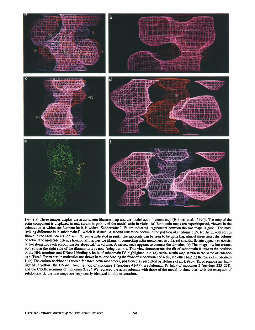
From the data shown in Fig. 3, we calculated a three- dimensional map of the filament density. These maps are dis- played as contour maps (Fig. 4) and as solid surfaces (Fig. 5). The pointed end of the averaged actin filament was deter- mined by comparison to the reconstruction presented previ- ously by Bullitt et al. (1988). In that data set the pointed end was assigned based on correlation of an acrosomal filament with the acrosomal bundle, for which the polarity is known. All filament images in this paper are displayed with the pointed end up. We displayed our actin map and the map de- rived from the atomic model (Holmes et al., 1990) on an Evans and Suthedand display (Fig. 4). Our actin map is shown in orange, the actin-binding protein, scrnin, in pink, and the map of the model actin in violet. Fig. 4, a and c, shows the actin maps superimposed. The two maps are very nearly identical both in volume and in shape. For instance, an arrow in Fig. 4 c points to a region where the two maps coincide nearly perfectly. There is a shift of density indicated by the double arrow in Fig. 4 c. In the model this density arises from subdomain U. Differences can also be identified in Fig. 4 a. The arrow points to a subdomain II which is shifted. The double arrow points to a portion of subdomain IV, which also appears to shift position in the two maps.
l l ~ ll ~ ~ l l l l l l[~ l l l l ~ . . . . . . . . . . . . . . . . . . . . . . . . . . . . . II ............ ll l l l l l~ l l l l l 1 l l ] " 7
II ................ .......... "6
. . . . . . . . . . • .... 2
\ . . ,.,. • ............ 10 a b ¢
Figure 3. Plot of G,j(R) amplitudes (solid lines) and phases (dot- ted lines). Phases are scaled from 0 to 360 °. Amplitudes for the equator are scaled to fit the graph. Amplitudes for layer lines are plotted using the same scaling for each data set, except where indi- cated by an X/0 notation. Three data sets are shown: (a) the ac- tin-scruin filament, (b) the actin filament generated from the atomic model of actin (Holmes et al., 1990), and (c) the actin por- tion of the actin-scruin filament. The Bessel order and layer line positions (reciprocal Angstroms) are listed for each layer line. The actin helix is characterized by strong layer lines 1 (396 A), 2 (198), 5 (69.5), 6 (59.1), 7 (51.4) and 8 (45.5). Comparison of the ac- tin-scruin data with the model actin data shows the major differ- ence is a shift of the former towards the meridian, consistent with the presence of the large protein mass of scruin at an outer radius. The two actin data sets correspond almost perfectly. At higher reso- lution, the 13.7-A meridional reflection of the Limulus filament is deafly visible, though attenuated •10-fold as compared with the model data. This is due at least in part to the contrast transfer func- tion of the electron microscope, which is approaching its first node.
The protein scruin is shown along with the map of actin in Fig. 4, b and d. In Fig. 4 f scruin is displayed with the map of the model actin, emphasizing the close similarity be- tween the two actin maps. Fig. 4 e shows the ct carbon back- bone of three actin monomers of the atomic model of the fila- ment (Holmes et al., 1990). Three segments of chain are highlighted in yellow: the DNase I loop of the first actin
The Journal of Cell Biology, Volume 123, 1993 340
Figure 4. These images display the actin-scruin filament map and the model actin filament map (Holmes et al., 1990). The map of the actin component is displayed in red, scruin in pink, and the model actin in violet. (a) Both actin maps are superimposed, viewed in the orientation at which the filament helix is widest. Subdomains I-IV are indicated. Agreement between the two maps is good. The most striking difference is in subdomain II, which is shifted. A second difference occurs in the position of subdomain IV. (b) Actin with scruin shown in the same orientation as a. Scruin is indicated in pink. The molecule can be seen to be quite big, almost three times the volume of actin. The molecule extends horizontally across the filament, connecting actin monomers in different strands. Scruin appears to consist of two domains, each accounting for about half its volume. A narrow neck appears to connect the domains. (c) The image in a but rotated 90 °, so that the right side of the filament in a is now facing out in c. This view demonstrates the tilt of subdomain II toward the position of the NH2 terminus and DNase I binding c~ helix of subdomain IV, highlighted in e. (d) Actin-scruin map shown in the same orientation as c. Two different scruin molecules are shown here, one binding the front of subdomain I of actin, the other binding the back of sulxlomain I. (e) The carbon backbone is shown for three actin monomers, positioned as predicted by Holmes et al. (1990). Three regions are high- lighted in yellow: the DNase I binding loop of monomer 1 (residues 41-49), a subdomain IV helix of monomer 2 (residues 223-231), and the COOH terminus of monomer 3. (f) We replaced the actin subunits with those of the model to show that, with the exception of subdomain II, the two maps are very nearly identical in this orientation.
Owen and DeRosier Structure of the Actin-Scruin Filament 341
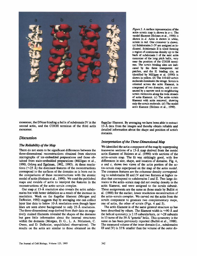
Figure 5. A surface representation of the aetin-scruin map is shown in a-c. The model filament (Holmes et al., 1990) is shown in d. Actin is shown in white, scruin in red. One crossover is shown. (a) Subdomains I-IV are assigned as in- dicated. Subdomain II is tilted forming a region of continuous density up to the back of subdomain I of the next actin monomer of the long pitch helix, very near the position of the COOH termi- nus. The scruin binding sites are indi- cated by the three transparent red patches, and the $1 binding site, as identified by Milligan et al. (1990) is shown in yellow. (b) The ll0-kD scruin molecule dominates the image. Scruin is oriented across the actin filament, is composed of two domains, and is con- nected by a narrow neck to neighboring scruin molecules along the twin strands of actin filament. (c) The actin-scruin filament with actin removed, showing only the scruin molecule. (d) The model actin filament (Holmes et al., 1990).
monomer, the DNase binding et helix of subdomain IV in the second actin, and the COOH terminus of the third actin monomer.
Discussion
The Reliability of the Map There do not seem to be significant differences between the three-dimensional reconstructions obtained from electron micrographs of ice-embedded preparations and those ob- tained from stain-embedded preparations (Milligan et al., 1990; Orlova and Egelman, 1992, 1993). At these resolu- tions ("~25 A) the dominant features of the reconstructions correspond to the surfaces of the domains as is born out in the comparisons of these reconstructions with the atomic model of actin (Holmes et al., 1990). We used the published maps and models of actin to interpret the features in the reconstructions of the actin-scruin complex.
Our map at 13-A resolution also reveals the actin subdo- mains but with better definition as a result of the increase in resolution. Work on the flagellar filament (Morgan and DeRosier, 1992) suggests that by averaging one can collect layer line data to below 10-A resolution even though layer lines are seen above background to only 25-A resolution. The three-dimensional map derived from their data on nega- tively stained filaments revealed the shapes of the domains but gave little information about the internal structures within the domains (Morgan, D. G., L. A. Melanson, C. Owen, and D. DeRosier, unpublished observations). The results on the actin are similar to those obtained on the
flagellar filament. By averaging we have been able to extract 13-A data from the images and thereby obtain reliable and detailed information about the shape and position of actin's domains.
Interpretation of the Three-Dimensional Map We identified the actin coml~o nent of the map by superposing transverse sections of a 13-A map derived from the model actin filament of Holmes et al. (1990) with sections of the actin-scruin map. The fit was strikingly good, with few differences in size, shape, and location of domains. Fig. 4, a and c, shows two views of the actin portion of the ac- tin-scruin map superposed on the map of the actin model. The common features are the columnar density correspond- ing to subdomains III and IV and two features at higher ra- dius that correspond to subdomains I and II. Two large do- mains in the actin-scruin map did not overlay density in the actin filament, and were assigned to the scruin subunit. These assignments are the same as those made by Bullitt et al. (1988) for the earlier, lower resolution reconstruction of the actin-scruin complex. We carved out the actin from the scruin component to generate two complementary maps, one of actin, the other of scruin (Figs. 4 and 5).
The actin filament is of the same general structure as has been described by others. The filament width is '~90/~ and the helical symmetry is 2.15 subunits/turn, or "o28 subunits in 13 turns of the 59-/~ "genetic" helix. This symmetry is the same as has been previously reported (Bullitt et al., 1988). The measured volume of the inner domain (i.e., subdomains III and IV) is 33 % smaller than the volume of the outer do-
The Journal of Cell Biology, Volume 123, 1993 342
main (subdomains I and II) in this map. In the atomic model the inner and outer domains are of approximately equal vol- ume. However, we found that in a 13-A map of the filament generated from the atomic model of actin the measured vol- ume of the inner domain is 20% smaller than the outer domain.
The scruin molecule, which binds with a 1:1 stoichiometry to actin, is 40 ]k in diameter and 95/~ long with the long axis transverse to the helix axis. The scruin subunit appears to consist of two domains, each ,,o40 x 40 x 45/~ in size. This is consistent with the observation that scruin is sensitive to proteolytic cleavage, leaving a 50- and 60-kD fragment (Bullitt et al., 1988; Schmid et al., 1991). Domain I makes contacts both with actin and perhaps with neighboring scruin subunits along the long pitch filament axis. There are no con- tacts between scruin molecules along the genetic helix. Do- main II of scruin makes contact with the next actin monomer along the genetic helix. In this way each scruin subunit forms a cross-bridge between the two long pitch strands of the actin filament. Scruin is therefore unlike the other actin bundling proteins such as fascin (DeRosier et al., 1977) in that its two actin binding domains are not used to cross-link filaments into the bundle. Rather the cross-links result from interac- tions between scruin subunits on adjacent filaments as sug- gested by Bullitt et al. (1988).
Whether or not subunits at a point of apparent contact ac- tuaily make contact cannot be determined at this resolution. It is, however, quite likely that they do and we will tentatively identify these as contacts as has been done in previous works (Milligan et al., 1990). Domain I of scruin makes two con- tacts with actin: one at subdomain I and the second with sub- domains UI and IV at their juncture. Domain II of scruin makes contact with subdomains I and II of the next actin along the genetic helix. These contacts are shaded in pink in Fig. 5 a. The two subdomains have quite different binding sites to actin.
Actin's myosin binding site has been localized to the region in Fig. 5 a shaded in yellow (Milligan et al., 1990; Kabsch et al., 1990). There is a region of partiai overlap of the bind- ing sites of scruin and myosin indicated by the orange color. This explains the observation that S1 does not decorate the actin filaments in an actin-scruin bundle (Tilney, 1975). The tropomyosin binding site on actin has also been determined and appears to correspond to a site on the junction between subdomains III and IV (Milligan et al., 1990). This seems to overlap with the scruin contact on the same subdomains and thus we would predict the binding of scruin would inter- fere with the binding of tropomyosin. Tropomyosin is not found in the bundle but there may be other explanations for its absence.
There appear to be four actin-actin contacts: two within each strand and two between strands. The first intra-strand contact is between subdomain IV on one subunit and subdo- main III on the next subunit in a strand (Fig. 4 a). The second intra-strand contact is between subdomain II and subdomain I (Fig. 4 d). The first inter-strand contact appears to be be- tween subdomain II and subdomain III of the next actin subunit along the genetic helix (arrow, Fig. 5 a). These con- tacts differ from that of Holmes et al. (1990) and Lorenz et al. (1993). We suggest these different contacts arise because of the altered position or structure of subdomain II. Finally, a contact appears approximately between subdomain III and
subdomain IV, linking the two strands near the axis of the filament (arrowhead, Fig. 5 a). This may be due to the hy- drophobic plug (residues 265-275) as suggested by Holmes et al. (1990).
The Actin Conformation
The shape of the actin subunit seen in the map is similar enough to that of the model (Holmes et al., 1990; Lorenz et al., 1993) and to that of Orlova and Egelman (1993) that we can identify the subdomains and therefore identify changes in the positions of the subdomains. Our map is most similar to the map of F-Mg 2÷ actin in the absence of Ca 2+ (Orlova and Egelman, 1993) and differs from the model of Holmes et al. (1990) and Lorenz et al. (1993) in the position of subdomain II. Subdomain II is of interest because it may be involved in conformational transitions (Orlova and Egel- man, 1993). In the case ofactin, subdomain II appears disor- dered (Orlova and Egelman, 1992) or moved radially inward (Orlova and Egelman, 1993; Lorenz et al., 1993) from the position predicted by Holmes et al. (1990). Subdomain II can, however, be seen in maps of actin filaments in the pres- ence of lithium or berylium fluorides (Orlova and Egelman, 1992), which serve as phosphate analogs. This subdomain appears to change position in response to a change in the bound nucleotide or metal ion (see Fig. 3 c, of Orlova and Egelman, 1993). In our map subdomain II appears at the same location in the F-Mg2+-ADP actin in the absence of Ca 2÷. In these filaments, subdomain II, relative to that in the Holmes et al. (1990) model, appears rotated by "o25 ° about the long axis of the monomer.
We suggest that this apparent rotation could be due to a change in conformation of the DNase I binding loop of subunit II permitting it to interact with the region at or near the COOH terminus of the next actin monomer along the long pitch helix and also with the ct helix (223-230) of the next actin along the genetic helix. Our reasons for suggesting this contact are as follows: the density corresponding to the DNase I binding loop is swung over toward the COOH termi- nus and the helix (223-230), and indeed appears to make contact in this region (double arrowheads in Fig. 4, a and c). A portion of subdomain IV at or near the helix appears shifted from its position in the atomic model (see Fig. 4 a). The loop, COOH terminus and helix involved are high- lighted in yellow in Fig. 4. It is possible, by moving the loop and the helix, to generate a region of contact near the COOH terminus.
O'Donoghue et al. (1992) suggest that the COOH terminus is important structurally because deletion of the last two residues of the COOH terminus leads to a more flexible fila- ment. The DNase I binding loop, in the absence of DNAse I, is likely to be highly flexible. Indeed its location is shifted albeit differently in the revised model of Lorenz et al. (1993). Analysis by molecular dynamics (Tirion and ben-Avraham, 1993) suggests that the et helix (223-230) might also be eas- ily moved. These results support but do not prove that such movements are possible. The reconstructed image shows shifts of density in these regions.
Amino acid side chains in the loop, the COOH terminus and the helix could if brought together make a hydrophobic interaction. The DNase I binding loop has several hydropho- bic residues (indicated in capital letters) (residues 41-49:
Owen and DeRosier Structure of the Actin-Scruin Filament 343
gin, gly, VAL, MET, VAL, gly, MET, gly, gln), as does the COOH terminus (PHE, cys) and the residues of the tx helix facing the DNase I binding loop (residues 223-231: PHE, glu, asn, glu, MET, ala, thr, ALA, ALA). These potential bydrophobic interactions together with the interactions with scruin domain II may hold subdomain II in this conforma- tion. There are now two different actin filaments (this work and Orlova and Egelman, 1993) in which part of subdomain II appears shifted azimuthally toward the helix (223-231) and thus it seems likely that this represents a new conforma- tion of the actin subunit. Additional experimental results will be needed, however, to determine whether the residues we suggest are indeed involved in the contacts.
We thank most gratefully Noreen Francis for her considerable help with the biochemistry of this project, Marie Craig for her assistance with the preparation of the figures, and Jim Griffith of Vertex Pharmaceuticals for generously sharing Voxray, used for preparing the surface view of the maps presented in this paper.
This work was supported by National Institutes of Health grant GM 26357 to D. J. DeRosier.
Received for publication 1 June 1993 and in revised form 26 July 1993.
References
Amos, L. A. 1975. Combination of data from helical particles: correlation and selection. J. Mol. Biol. 99:65-73.
Branton, D., C. M. Cohen, and J. Tyler. 1981. Interaction of cytoskeletal pro- teins on the human erythrocyte membrane. Cell. 24:24-32.
Bullitt, E. S. A., D. J. DeRosier, L. M. Coloccio, and L. G. Tilney. 1988. Three dimensional reconstruction of an actin bundle. J. Cell Biol. 107:597-611.
Burgess, D. R. 1987. The brush border: a model for structure, biochemistry, motility, and assembly of the cytoskeleton. Adv. Cell Biol. 1:31-58.
Demma, M., V. Warren, R. Hock, S. Dharmawardhane, and J. Condeelis. 1990. Isolation of an abundant 50,000-daiton actin filament bundling protein from dictyostelinm amoebae. J. Biol. Chem. 265:2286-2291.
DeRosier, D. J., and R. Censullo. 1981. Structure of F-actin needles from ex- tracts of sea urchin oocytes. J. Mol. Biol. 146:77-99.
DeRosier, D. J., and P. B. Moore. 1970. Reconstruction of three-dimensional images from electron micrographs of structures with helical symmetry. J. Mol. Biol. 52:355-369.
DeRosier, D. J., E. Mandeikow, A. Silliman, L. G. Tilney, and R. Kane. 1977. Structure of actin-containing filaments from two types of non-muscle cells. J. Mol. Biol. 113:679-695.
DeRosier, D. J., L. G. Tilney, and E. H. Egelman. 1980. Actin in the inner ear: the remarkable structure of the stereocilium. Nature (Lond.). 287: 291-296.
Dharmawardhane, S., M. Demma, F. Yang, and J. Condeelis. 1991. Compart- mentalization and actin binding properties of ABP-50: the elongation factor- 1 alpha of dictyostelium. Cell Motil. Cytoskeleton. 20:279-288.
Egelman, E. H. 1986. An algorithm for straightening images of curved filamen- tous structures. Ultramicroscopy. 19:367-374.
Flock, A., and H.C. Cheung. 1977. Actin filaments in sensory hairs of inner ear receptor cells. J. Cell Biol. 75:339-343.
Griffith, J. P., D. L. Griflith, I. Rayment, W. T. Murakami, and D. L. D. Caspar. 1992. Inside polyomavirus at 25-A resolution. Nature (Lond.). 355:652-654.
Holmes, K. C., D. Popp, W. G-ebhard, and W. Kabsch. 1990. Atomic model of the actin filament. Nature (Lond.). 347:44-49.
Huxley, H. E. 1969. The mechanism of muscular contraction. Science (Wash. DC). 164:1356-1366.
Kabsch, W., H.G. Mannherz, D. Suck, E. F. Pai, and K. C. Holmes. 1990. Atomic structure of the actin:DNase I complex. Nature (Lond.). 347:37--44.
Laemmii, U. K. 1970. Cleavage of structural proteins during the assembly of the head of bacteriophage T4. Nature (Lond.). 227:680-685.
Lorenz, M., D. Popp, and K. C. Holmes. 1993. Refinement of the F-actin model against x-ray fiber diffraction data by the use of a directed mutation algorithm. J. Mol. Biol. In press.
Maroux, S., E. Coudrier, H. Faracci, J. P. Gorvel, and D. Louvard. 1988. Mo- lecular organization of the intestinal brush border. Biochimie (Paris). 70:1297-1306.
Milligan, R. A., and P. F. Flicker. 1987. Structural relationships ofactin, myo- sin, and tropomyosin revealed by cryo-electron microscopy. J. Cell Biol. 105:29-39.
Milligan, R. A., M. Whittaker, and D. Safer. 1990. Molecular structure of F-actin and location of surface binding sites. Nature (Lond.). 348:217-221.
Moore, P. B., H. E. Huxley, and D. J. DeRosier. 1970. Three-dimensional reconstruction of F-actin, thin filaments and decorated thin filaments. J. Mol. Biol. 50:279-295.
Morgan, D. G., and D. DeRosier. 1992. Processing images of helical struc- tures: a new twist. Ultramicroscopy. 46:263-285.
O'Donnghue, S. I., M. Miki, and C. G. dos Remedios. 1992. Removing the two C-terminal residues of actin affects the filament structure. Arch. Bio- chem. Biophys. 293:110-116.
Odova, A., and E. H. Egelman. 1992. The structural basis for the destabiliza- tion of F-actin by phosphate release following ATP hydrolysis. J. Mol. Biol. 227:1043-1053.
Orlova, A., and E. H. Egelman. 1993. A conformational change in the actin subunit can change the flexibility of the actin filament. J. Mol. Biol. 232:334-341.
Owen, C. H., D. J. DeRosier, and J. Condeelis. 1992. Actin crosslinking pro- tein EF-la of Dictyostelium discoideum has a unique bonding rule that al- lows square-packed bundles. J. Struct. Biol. 109:248-254.
Rayment, I., H. M. Holden, M. Whittaker, C. B. Yohn, M. Lorenz, K. C. Holmes, and R. Milligan. 1993. Structure of the actin-myosin complex and its implications for muscle contraction. Science (Wash. DC). 261:58-65.
Schmid, M. F., P. Matsudaira, T.W. Jeng, J. Jakana, E. Towns-Andrews, J. Bordas, and W. Chin. 1991. Crystallographic analysis of acrosomal bundle from Limulus sperm. J. Mol. Biol. 221:711-725.
Schroder, R. R., D. J. Manstein, W. Jahn, H. Holden, L Rayment, K. C. Holmes, and J. A. Spudich. 1993. Nature (Lond.). 364:171-174.
Stewart, M., R. W. Kensler, and R. J. C. Levine. 1981. Structure of Limuhis telson muscle thick filaments. J. Mol. Biol. 153:781-790.
Tilney, L. G. 1975. Actin filaments in the acrosomal reaction of Limulus sperm. J. Cell Biol. 64:289-310.
Tirion, M. M., and D. ben-Avraham. 1993. Normal mode analysis of G-actin. J. Mol. Biol. 230:186-195.
Vibert, P., and R. Craig. 1982. Three-dimensional reconstruction of thin fila- ments decorated with a Ca2+-regulated myosin. J. Mol. Biol. 157:299-319.
Xue, F., and L. Cooley. 1993. Kelch encodes a component of intercellular bridges in Drosophila egg chambers. Cell. 72:681-693.
Yang, F., M. Demma, V. Warren, S. Dharmawardhane, and J. Condcelis. 1990. Identification of an actin-binding protein from Dictyostelium as elon- gation factor la. Nature (Lond.). 347:494-496.