35
A 40+ dB Gain Antenna Made from Paper *Flying Antenna/QSO A New Antenna Theory *An Inexpensive SWTL *An All-Band Antenna Q&A *Construction Article Available

A 40+ dB Gain Antenna Made from Paper
*Flying Antenna/QSO
A New Antenna Theory
*An Inexpensive SWTL
*An All-Band Antenna
Q&A
*Construction Article Available

2John Kraus, W8JK
John Kraus, W8JK

3
Sonoma County, California
North

4
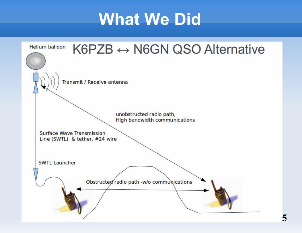
Radio Paths Beween K6PZB/N6GN
5
What We Did

6
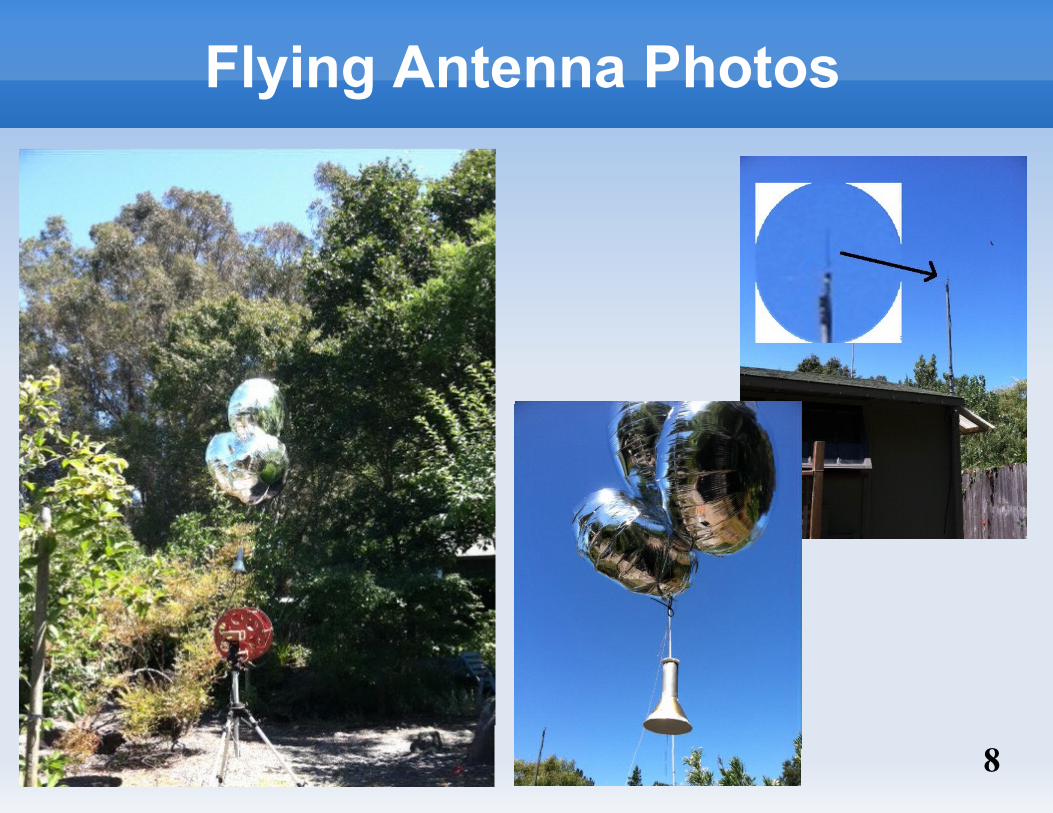
A Flying Antenna
The ”Mercury Capsule” an extended Discone

7
Winder Photos
8
Flying Antenna Photos

9
Predicted Signal Vs. Height
Actual improvement > 40 dB

10
A New Antenna Theory
Flying Antenna/QSO
A New Antenna Theory
An Inexpensive SWTL
An All-Band Antenna
Q&A

11
Traditional Antenna Theory
E=j k d I 04 r
sin e j k t−kr
The traditional development of dipole antenna theory is by integrating current in infinitessimal elements. This reveals both pattern and impedance.
For most of us, there is little added understanding of how or why an antenna operates.

12
Dipole Pattern and Feed Impedance
Antenna pattern vs. dimension (wavesize)
In these plots, the antenna is positioned vertically in free space at the center of the plot.
Notice that for some dimensions there is zero signal broadside to the antenna.
13
Dipole Representations
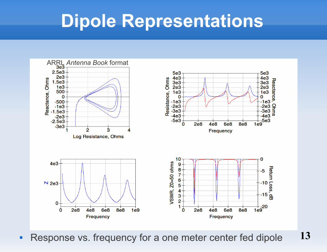
Response vs. frequency for a one meter center fed dipole
ARRL Antenna Book format

14
Beyond Z0= 50 ohms
Note broader match bandwidth at Z
0= 6 kohms & full wave.
A circle around Smith Chart center is characteristic of a mismatched transmission line, Z
0=Z
ref≠ Z
load

15
The Dipole as Mismatched Lines
Feedpoint impedance (4NEC2) of a thin 1 meter dipole plotted on a Smith chart with a reference impedance of 754 ohms, twice the impedance of a wave in free space.

16
A Circuit Designer's Dipole Model
For a radio communications system designer, the goal is usually to transfer as much of the transmitter power to the radiation resistance as possible

17
Dipole Z-Axis Near-Field Near-field electric field
strength parallel to the dipole conductor for center fed dipoles of different wavelengths. (from 4NEC2).
Due to symmetry and cancellations, E
x & E
y
each become zero in the far field and may be ignored.
Notice that significant E
z components are
present only at the ends and (sometimes) at the center of the dipole.
.5λ 1λ
2λ1.5λ

18
A New Interpretive Antenna Model
The radiation pattern and impedance of a dipole (or monopole) can be modeled as sources of longitudinal electric field at C and D, with sources D acting as mismatched loads to uncoupled, non-radiating 377 ohm surface wave transmission lines, along with a tip-tip capacitance which is only significant at small antenna wave size.
”Thus, a single device, in this case the dipole, exhibits simultaneously properties characteristic of an antenna, a transmission line, and a resonator.” John Kraus, W8JK, Antennas, McGraw-Hill 1950, Chapter 1

19
An Inexpensive SWTL
*Flying Antenna QSO
A New Antenna Theory
*An Inexpensive SWTL
*An All-Band Antenna
Q&A
*Construction Article Available

20
A New Type of Transmission Line
This SWTL is not G-line as shown in ARRL VHF Manual, QST or reference books.
The conductor needs no insulation The wave is not slowed but travels right at the
speed of light. Velocity factor is 1.0 Not only for microwave. With suitable launchers
this SWTL can operate at arbitrarily low frequency.

21
SWTL Photos

22
>140 Mhz Klopfenstein Taper Launcher
Launchers are surface waveguide adapters that convert the impedance and mode of a wave in coax to those on the single conductor waveguide

23
Measurements of 100' SWTL vs. Coax
144 MHz & 400 MHz Launchers/100' SWTL comparedWith 100' Times-Microwave LMR-400 Coaxial Cable

24
An All-Band Antenna
*Flying Antenna/QSO
A New Antenna Theory
*An Inexpensive SWTL
*An All-Band Antenna
Q&A
*Construction Article Available
25
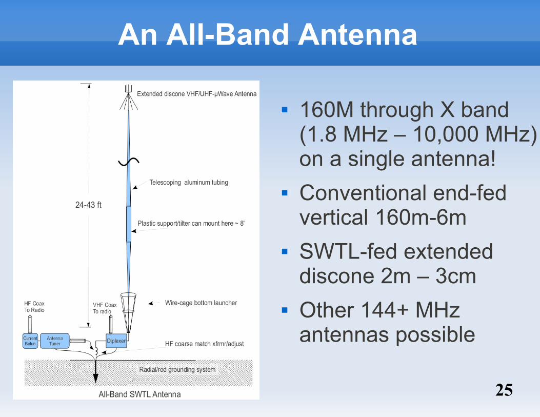
An All-Band Antenna
160M through X band (1.8 MHz – 10,000 MHz) on a single antenna!
Conventional end-fed vertical 160m-6m
SWTL-fed extended discone 2m – 3cm
Other 144+ MHz antennas possible

26
Match of 33' Vertical
Measured match of 33' vertical, .3 – 250 Mhz before SWTL launcher and VHF-microwave antenna are added

27
Impedance w/o & w/ SWTL
Note the reduction in resonance responses due to the increasing termination of the SWTL above ~75 MHz. Launcher/Termination was a 400 Mhz Klopfenstein taper in this example.

28
Bottom Launcher Photos

29
Launcher/Discone Photos

30
All-Band Antenna Photos

31
All-Band K6PZB <---> N6GN WSPR

32
All-Band Antenna Performance
Typical 24 hour period for All-Band Antenna running 5 watts on WSPR & 160 through 10 meter bands

33
Permission to Use SWTL Technology
The surface wave transmission line technology described here is patented and requires licensing agreements to build or use. However Corridor Systems Inc, the patent holder, is permitting licensed radio amateurs worldwide to build and deploy devices and systems which use it for their personal, non-commercial use, under the terms of their amateur licenses. For other use contact Corridor Systems Inc1. 3800 Rolling Oaks Road, Santa Rosa, California 95404, USA.
1 http://www.corridorsystems.com

34
Summary and Q&A ”All models are wrong but some are useful.” - George Box
A new model of the dipole is useful and provides insights which enable new antenna and transmission line designs.
Three inexpensive and easy-to-build designs are presented here. Complete construction articles available*.
Permission to use the underlying SWTL technology is being granted to licensed amateurs for their personal use.
*(1) Mercury Capsule
Fly-able (fixed station) .4 to 20 Ghz extended discone made from paper (brass), needs SWTL launcher from (2)
*(2) SWTL
General amateur use, low loss, lightweight broadband surface wave transmission line for ~100 Mhz to 20 GHz
*(3) All-Band Antenna
Vertical antenna for 1.8 Mhz through 10 GHz amateur use.


