Page 1
A BEAM FINITE ELEMENT MODEL INCLUDING WARPING
Application to the dynamic and static analysis of bridge decks
Diego Lisi
Department of Civil Engineering of Instituto Superior Técnico, October 2011
ABSTRACT
The present dissertation deals with the study of the dynamic and static effects on continuous beams of thin-walled cross-sections through the formulation a of a finite element.
When a thin-walled cross-section of a beam structure has open profile the deformability greatly exceeds
that of a compact section, because of to the out-of-plane deformations of this type of shapes when acted by torsion, being this effect due to the warping of the cross-section.
The exact analysis of thin walled beams considering the warping phenomena is usually difficult in its
implementation by numerical codes for their mathematical solutions that are too complicated for routine calculations.
The classic beam theories are analyzed to obtain the set of equations governing the problem. The
variational principles are used in order to obtain an approximation model and purpose a finite beam element for the analysis of thin-walled beams.
In static, straight and generally supported structures are analyzed, while in dynamic the torsional and
lateral free-vibration and forced vibration is investigated. The results of the analysis and the compliance with the classic beam theory are discussed.
The aim of the work is to propose a generalized thin-walled beam model for the railway high-velocity
bridge analysis and design. A simple numerical example of multi-span bridge is illustrated in order to evaluate the performance of different types of cross-sections when dynamic effects are considered.
KEYWORDS: thin-walled beams, bridge deck, finite element method, warping, beam element, dynamic analysis, moving load.
Page 2
3
1. INTRODUCTION
The bridge decks given their geometry can be globally analyzed through a beam model with a thin-walled
cross-section. Therefore, the bridge deck structural behavior can be analyzed through that of a thin-walled beam,
taking in account in particular the cross-section warping.
The warping deformability of an open thin-walled section greatly exceeds that of a closed section, either in
multicellular or monocellular type. This happens because the open section warps and a non-uniform torsion
stress contribution occurs along the longitudinal direction. Hence, the analysis of these sections cannot neglect
their warping, which causes out-of plane deformations and constitutes the first source of torsional stiffness for
these cross-section types. On the other hand, the main contribution to the torsional stiffness of the closed cross-
sections is due to the uniform shear strain considered along the wall thickness.
The present work deals with the formulation of a model allowing the simplified analysis of straight thin-
walled beams generally supported and generally loaded, both in static and dynamic load cases. The major
propose is the application of this beam element to the analysis of bridges, in particular due to the action of a
moving load.
2. THIN WALLED BEAMS GOVERNING EQUATIONS
2.1. Kinematics
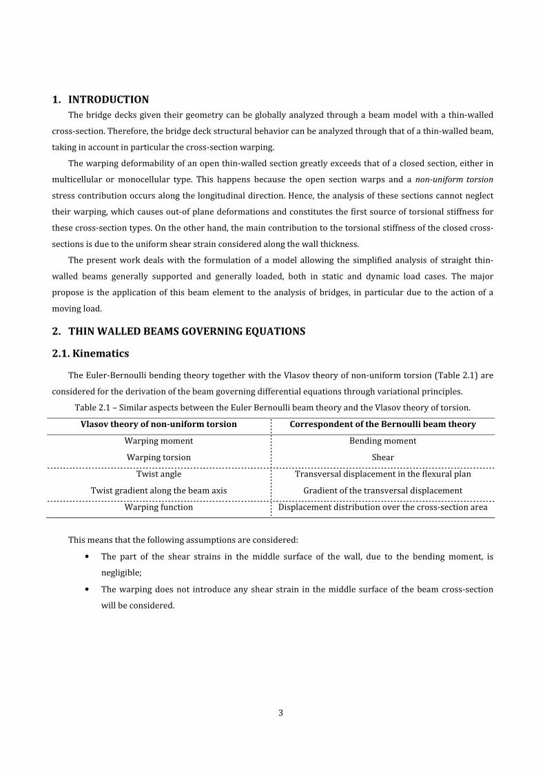
The Euler-Bernoulli bending theory together with the Vlasov theory of non-uniform torsion (Table 2.1) are
considered for the derivation of the beam governing differential equations through variational principles.
Table 2.1 – Similar aspects between the Euler Bernoulli beam theory and the Vlasov theory of torsion.
Vlasov theory of non-uniform torsion Correspondent of the Bernoulli beam theory
Warping moment Bending moment
Warping torsion Shear
Twist angle Transversal displacement in the flexural plan
Twist gradient along the beam axis Gradient of the transversal displacement
Warping function Displacement distribution over the cross-section area
This means that the following assumptions are considered:
• The part of the shear strains in the middle surface of the wall, due to the bending moment, is
negligible;
• The warping does not introduce any shear strain in the middle surface of the beam cross-section
will be considered.
Page 3
4
z,uz
x,ux
y,uy
P(yP,zP)
ϕ
y
z
(uy,uz)(y,z)
C(yC,zC)
Figure 2.1 - Principal displacements and system coordinates of the beam.
The displacement field of a thin walled beam element (figure 2.1)can be described as follows:
�� = �� − �� − �� (2.1)
u� = ξ� + �� − �� (2.2)
����, � = ��� − �� − ������� − �� − ������� − ������ (2.3)
where ��� is the axial displacement, �� and �� are the �,z-displacements, respectively, due to bending and
is the twist angle. ��� is the warping coordinate, described as follows:
��� = � ℎ���
�� − Ω∮ �
!� ��
"�
#+ $% (2.4)
in which $% can be obtained imposing the axial virtual work to be null, i.e. for P or C ∮ ��� "���� = 0.
This function depends only of the geometrical properties of the cross-section and is defined with the solution
of Saint Venant’s torque. Notice that for the open section the warping function is given by ��� = ' ℎ��� �� + c%
because Ω = 0.
2.2. Statics
The strain and stress fields of the beam element can be deduced from the displacement field described by
(2.1), (2.2), (2.3) in order to find the expression of the strain energy density which is given by:
) = %* +,* + %
* -.* (2.5) where ,, . are the axial and shear strains, respectively, + is the Young modulus and - is the shear modulus. The
load is given in terms of volume forces, so the external work per unit volume can be expressed as follows
/ = 0��� + 0��� + 0��� (2.6)
The total potential energy is given as follows:
1 = � �) − /�12
= � 312 +,* + 1
2 -.* − �0��� + 0��� + 0���6 �12
= 0 (2.7)
that for a beam element can be written in terms of energy per unit length giving the following:
1 = � 7 8�, ��, , �, ��, ��, ��, ��� , ���, ���� , ����9 ��:
(2.8)
where 7 is a functional, depending on all the generalized displacements of the thin-walled beam element.
Page 4
5
The minimum potential energy states that at the minimum of the energy the first variation of the functional must
vanish for the arbitrary variations ;<=��, being <=�� the generalized displacement considered that satisfies the
kinematic boundary conditions. This is expressed by ;1�<==0. The integration by parts of the first variation
;1�<= leads to the boundary condition terms and to the differential equations represented in table 2.1.
Notice that in order to uncouple these equations, the in-plane twist is considered around the shear center,
while bending and extension are considered in relation to the elastic center.
Table 2.2 –Equilibrium equations and boundary conditions.
Equilibrium equation Kinematic Static
Extension �>�� + <� = 0 � >
Bending
1� = �?��� + @�
�1��� + <� = 0
�� , −�′� 1� , ?�
1� = �?��� + @�
�1��� + <� = 0
�� , −�′� 1� , ?�
Torsion
A = AB + AC + D
�A�� + @E = 0
, � A, AC, AB, ?B
2.3. Dynamics
When the time variation of the kinematic field is considered the beam kinetic energy can be defined as
follows:
A = � 12 F���G * + ��G * + ��G *�1
2 (2.9)
The dots define integration over time " and F [IJ/@L] is the mass per unit volume of the material.
The integration over the cross-section of the eq.(2.9), after substituting the expressions of the velocities,
leads to the energy N per unit length of the beam, which allows to obtain the beam kinetic energy written as
follows:
A = � N��G , ��G , �� ,G G , �G��, �G��, G ���:#
(2.10)
where N is a second functional, depending on the velocities of the generalized displacement considered.
The solution for each generalized displacement satisfies the boundary conditions and respects the
Hamilton’s principle1, leading to the following expression
1 See (Clough & Penzien, 1982).
Page 5
6
� ;�A − 1�" = � O PAP<= ;<= + PA
P<G= ;<G= +PA
P<QG � ;<�G = −P1P<= ;<= − P1
P<=�;<=� − P1
P<=�� ;<=��R!S
!T�" = 0!S
!T (2.11)
where <= is the generic U-generalized coordinate relative to the U-degree of freedom. Integrating the velocity
dependent terms in eq. (2.11) by parts, a set of differential equations governing the dynamics of the beam
element can be obtained, being the equations for each degree of freedom presented in table 2.3.
Table 2.3 – Equations of motion, kinetic terms and boundary conditions.
Equation of motion Kinetic Static
Axial
effect −FV P*�
P"* + P*�P�* +V + <� = 0
P*�P"* >
Bending
1� = P?�P� + @� + FW�P2���P"2
P1�P� + <� − FV OP2��P"2R + FX�Y
P2P"2
= 0
P2��P"2
,P2��′P"2
1� , ?�
1� = P?�P� + @� + FW�P2���P"2
PP� 1� + <� − FV OP2��P"2
R − FX�YP2P"2
= 0
P2��P"2
,P2��′P"2
1� , ?�
Torsion
A = FWBBP2
P"23P
P�6 + P?BP� + AC + D
�A�� − F[W�Y + W�Y\ P2
P"2+ FX�Y
P2��P"2− FX�Y
P2��P"2+ @E = 0
P2′P"2
, P2P"2
,P2��P"2
,P2��P"2
A, ?B
3. FINITE ELEMENT MODEL
3.1. FEM approximation
The governing equations of thin-walled beams structural behavior are partial differential equations, being
the corresponding analytical solutions difficult to obtain for an arbitrary cross-section. For this reason the
corresponding displacement field has been approximated and a weak formulation was derived according to the
Galerkin weighted residual method in order to define a finite element, which allows the analysis, both static and
dynamical, of thin-walled beams with arbitrary cross-section. The approximation of the displacement field is
represented by the following vector
]^�� = _�`�� ��`�� − ���`�� ��`�� ���`�� `�� − �`��a
= bc^ de^ −
�de^�� df^ −
�df^�� dg^ −
�dg^�� h
ijjjjjjk lm^le^le^lf^lf^lg^lg^no
ooooop
(3.1)
Linear interpolation functions c^ and Hermite polynomials dq^ are used as approximation functions in
order to obtain the continuity and completeness required for the finite element beam model.
Page 6
7
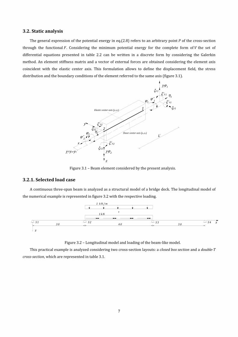
3.2. Static analysis
The general expression of the potential energy in eq.(2.8) refers to an arbitrary point r of the cross-section
through the functional 7. Considering the minimum potential energy for the complete form of 1 the set of
differential equations presented in table 2.2 can be written in a discrete form by considering the Galerkin
method. An element stiffness matrix and a vector of external forces are obtained considering the element axis
coincident with the elastic center axis. This formulation allows to define the displacement field, the stress
distribution and the boundary conditions of the element referred to the same axis (figure 3.1).
Elastic center axis (yC,zC)
Shear center axis (ya,za)
y
ξy
ξz
ηϕ
z
ϕ 'x
ξ 'z
ξ 'y2
2
2
2
2
2
2
ξ 'z1
ξ 'y1
ξz1
η1
ξy1
ϕ1
ϕ '1
2
1
y=yA-yC yϕ2
yϕ1
Le
Figure 3.1 – Beam element considered by the present analysis.
3.2.1. Selected load case
A continuous three-span beam is analyzed as a structural model of a bridge deck. The longitudinal model of
the numerical example is represented in figure 3.2 with the respective loading.
1 k N
4 03 0 3 0
1 k N / m
x
z
+
S 1 S 2 S 3 S 4
Figure 3.2 – Longitudinal model and loading of the beam-like model.
This practical example is analyzed considering two cross-section layouts: a closed box section and a double-T
cross-section, which are represented in table 3.1.
Page 7
8
Table 3.1 – Cross-section layouts and geometrical properties.
Box Section Double-T Section
Bb b
h tw
tfC
z
y
ab1
E
tf1
Bb b
h tw tw
tfC
z
y
t[@] 7.30 6.65
D[@] 3.00 3.33
"u[@] 0.50 0.80
"v[@] 0.35 0.35
"v%[@] 0.30 -
w 23° -
ℎ[@] 2.28 3.03
The results are presented in figure 3.3 for the transverse displacements and the twist of the double-T
section. Notice that the horizontal displacements appear as a natural consequence of the coupling between ��
and , which derives from the consideration of the developed element that is represented by figure 3.1.
A comparison between the double-T section analyzed and the box section, considering the warping effect,
can be described by showing the different torsional behavior. The -rotation of the cross-section compared
between the box-section and the double-T section is shown in figure 3.4, while the Saint Venant torsion
AC = ′-y along the bridge axis is represented in figure 3.5 for the same two examples of deck section.
Page 8
9
Cuy
C
uz
Cϕ
Figure 3.3 – Displacements and rotation of the bridge model with double-T section (FEM model).
Figure 3.4 - Twist values along the beam axis for the double-T section and for the Box section.
12
Figure 3.5 – Saint Venant torsion contribute for the double-T section and for the Box section.
0 10 20 30 40 50 60 70 80 90 100
-1
0
1
x 10-6
Displacement of the2 d.o.f
0 10 20 30 40 50 60 70 80 90 100
-5
0
5
x 10-5
Displacement of the4 d.o.f
0 10 20 30 40 50 60 70 80 90 100
-2
0
2
x 10-6
Displacement of the6 d.o.f
0 10 20 30 40 50 60 70 80 90 100
-5
0
5
10
x 10-7
Double-T deck Box deck
0 10 20 30 40 50 60 70 80 90 100
-2
0
2
x 104
Double-T deck Box deck
[rad]
AC[N.m]
�[m]
�[m]
[m]
[rad]
x[m]
x[m]
x[m]
[m]
Page 9
10
3.2.Dynamic analysis
The finite element model is used in the sequel for solving the problem of vibration, where the MDOF2 system
is described by a generic form of the algebraic equations, which written for the undamped vibration leads to the
following equation
z{| + }{ = ~ (3.2)
The equation of motion is composed by the fundamental element matrices of the structural system: the mass
matrix z and the stiffness matrix }
The coupling between generalized displacements for non-symmetric sections can be taken into account,
being a general element mass matrix obtained through the variational principles for a 7 DOF3 beam element. This
matrix refers, as the stiffness matrix, to the elastic centre axis of the beam element. The velocity contributions of
the element defined are represented in figure 3.6 for a C-beam.
Centroid axis (y C,zC)
Shear centre axis (y a,za)
y
ξy
ξz
ηϕ
z
ϕ 'x
ξ 'z
ξ 'y2
2
2
2
2
2
2
ξ 'z1
ξ 'y1
ξz1
η1
ξy1
ϕ1
ϕ '1
2
1
y=yA-yC yϕ2
yϕ1
Le
..
.
.
..
.
.
.
.
.
.
.
.
.
.
Figure 3.6 - Thin-walled C-beam element and coupled kinematic field.
When all the matrices in eq. (3.2) are known and assembled for the system analyzed, the discrete equation
can be solved by a frequency analysis: frequency equations of the system are polynomial equations that allow to
obtain for each DOF a mode of vibration. The mode shapes and the mode frequency are the solution of an
eigenvalues equation that can be solved by FEM model.
2 Multi-Degrees Of Freedom. 3 Degree Of Freedom.
Page 10
11
4. DYNAMIC RESPONSE TO MOVING LOADS
4.1. Numerical modeling of dynamical response
This chapter deals with linearized modal analysis of the combined flexural-torsional vibration of general
multi-spans beams with monosymmetric cross-sections.
The orthogonality properties of the normal coordinates may be used to simplify the equations of motion of
the MDOF system. For the damped system the general form of the dynamic equations is given by
z{| + �{G + }{ = ��� (4.1)
where � is the damping matrix of the system assembled considering the orthogonality conditions by the Rayleigh
method. The equation (4.1) can be solved by using the finite element model. The eq.(4.1) can be written in terms
of normalized coordinates to obtain an independent SDOF equation for each mode of vibration of the structure
and then obtain the displacements expressed in geometric coordinates by the modal superposition method. The
time integration is developed by a time-stepping method, i.e. the Newmark method.
4.2. Numerical example
A numerical example of a three-spans bridge loaded by a moving vertical force of constant speed acting
eccentrically is presented in the following section. The analysis is performed by the finite element formulated in
the present work. The geometry in the longitudinal direction is represented in figure 4.1, being the bridge decks
compared the same of table 3.1.
C
z
y
z
y
e PZ
C
e PZ
4030 30
z
PZ=1000kN
x
va)
b)
A'
A
Section AA'
Figure 4.1 - Longitudinal beam-like model (a) and layout of the cross-section analyzed (b).
The load eccentricity considered in the numerical example is also constant and its value is fixed to � = 2.5@.
The dynamic behavior of the bridge is investigated for a set of five different speed values of the load, considering
a maximum speed of 350 km/h that corresponds to a design speed of 420 km/h for high speed railway bridges.
For different speeds the results obtained for the twist angle values are shown in terms of dynamic influence
lines in figure 4.2 and in figure 4.3, where the twist angle of the double-T section and of the Box girder section is
compared.
Page 11
12
The oscillation peaks that characterize these functions are due to the frequencies of vibration: the lateral-
torsional modes have higher frequencies when compared with those of the flexural modes in the vertical plan
(Figure 4.2).
The box section has much more torsional stiffness than the double-T section and this corresponds to a
rotation shape function that tends to that of the static loading at the same section (Figure 4.3). Hence, the
magnitude of the maximum twist rotations is smaller for box sections. These results are confirmed in figure 4.4,
which shows that the twist rotations of the box girder section do not depend of the velocities of the moving load
if compared with those of the double-T section (Figure 4.4). Notice that the resonance peaks are observed for the
double-T sections, but their maximum is reached with fairly high load velocities because of the high frequency of
the lateral-torsional vibration modes.
Figure 4.2 - Dynamic influence lines of the twist φ at the section AA’ (double-T section).
Figure 4.3 - Twist of the bridge sections (load speed: 420 km/h).
-0.06
-0.01
0.04
0.09
0.14
0 10 20 30 40 50 60 70 80 90 100
φ[rad*
E-03]
x[m]
v=200 km/h
v=250 km/h
v=300 km/h
v=350 km/h
v=420 km/h
-0.06
-0.03
0
0.03
0.06
0.09
0.12
0.15
0 10 20 30 40 50 60 70 80 90 100
φ[r
ad
*E-0
3]
x [m]
Box girder section
Double-T section
Page 12
13
Figure 4.4 - Maximum twist rotation of the section AA’ for various speed values.
5. CONCLUDING REMARKS AND FUTURE DEVELOPMENTS
The analysis performed in this work is focused on the consideration of the torsional response of both open
and closed cross-sections of thin-walled beams. For this reason a finite element model with seven degrees of
freedom for each end has been formulated and implemented through a numerical code.
The axis of reference of the beam element has been considered as the elastic center according to the thin-
walled beam theory. The model that has been presented allows a simplified analysis of straight thin-walled beam
with arbitrary boundary conditions and generally loaded, both in static and dynamic load cases. The major
propose is the application of this beam element to the analysis of bridges. The proposed method can be used by
practicing engineers for obtaining accurate analysis results of such constructions.
The model presented may be easily implemented into any computer program for static analysis of
constructions.
In static, basic examples of generally loaded beams with different cross-sectional behaviors have been
presented for understanding the influence of warping in the displacement field and stress analysis. The exact
results obtained by (Kollbrunner & Basler, 1969) have been simulated in order to check the accuracy of the
obtained solution. Also a comparison with ABAQUS has been performed in order to check the stiffness method
developed in the work.
A study of convergence has been presented for the finite element model developed by increasing the
elements of the mesh until it was reached a sufficiently good approximation. Also two thin-walled cross-sections,
a double-T and a box girder, of a three-span bridge layout have been studied and the lateral-torsional response
in terms of displacements and forces was obtained.
In dynamics, the comparison between the two cross-sections mentioned above has been performed. The
modal superposition method has been used in order to obtain the structural response and obtain dynamic
influence lines for the thin-walled beams analyzed. The bridge model response confirmed that the warping
deformation greatly affects its behavior when the open section is considered.
0.08
0.09
0.10
0.11
0.12
0.13
0.140.15
0.16
0.17
120 150 180 210 240 270 300 330 360 390 420
Tw
ist
φ max[r
ad
*E-0
3]
Speed v [km/h]
Double-T section
Box girder section
Page 13
14
The presented model could be considered as the first step tending to a more complete formulation
accounting for several aspects that have not been considered, as
• The addition of the Benscoter’s consideration of the distorsion in the degrees of freedom of the finite
element, which is an important aspect in the analysis of box girder bridge sections;
• The variation of the cross-section height along the beam axis, important specially for the analysis of
open bridge sections because of the high values of the hogging moments on the bearing sections;
• The consideration of curved bridges in plane, with arbitrary types of cross-sections;
• The compatibility with the Eurocodes relative to the rail traffic model that should be considered as
traffic loads. This aspect involves the consideration of load models more complex than the simple
load considered by the analysis, i.e. the load models for real trains(HSLM4 model);
• Consideration of track-structure interactions that must be taken into account according to the EN
1991-2.
• The consideration of support conditions defined at the real point of their applications, i.e. the
bearings of a real multi-span bridges at the pier sections.
6. References
Benscoter, S. (1954). A theory of torsion bending for multicell beams. Journal of Applied Mechanics , 25-34.
Cedolin, L. (1996). Torsione e taglio di travi a parete sottile. Milano: Edizioni Cusl.
Chopra, A. (1995). Dynamics of Structures- Theory and application to the Earthquake Engineering. Berkeley:
Prentice Hall,Inc.
Clough, R., & Penzien, J. (1982). Dynamics of structures. McGraw-Hill.
Cunha, R. (2007). Dinâmica de Pontes em Viga Caixão em Linhas Ferroviárias de Alta Velocidade (Master
Thesis). FEUP. (p-40). Dinâmica de Pontes em Viga Caixão em Linhas Ferroviárias de Alta Velocidade (Master
Thesis). FEUP. (p-40) . Porto.
Ferreira, A. (2010). Problemas De Elementos Finitos em Matlab. Lisbon: Fundação Calouste Gulbenkian.
Fish, J., & Belytschko, T. (2007). A First Course In Finite Elements. John Wiley & Sons Ltd.
Friberg, P. (1985). Beam element matrices derived from Vlasov's theory of open thin-walled elastic beams .
International Journal for Numerical Methods in Engineering , 1206-1218.
Fryba, L. (1999). Simply supported beam subjected to a moving constant force. In L. Fryba, Vibration of Solids
and Structures under Moving Loads (third edition) (pp. 13-56). Prague: Thomas Telford Ltd.
Gere, J. (1954). Torsional Vibrations of Beams of Thin-Walled Open Section. Journal Of Applied Mechanics ,
381-387.
Hibbit, K. a. (2007). ABAQUS users manual version 6.7. U.S.A., U.S.A.
Kollbrunner, C., & Basler, K. (1969). Torsion in Structures: An Engineering Approach. In C. Kollbrunner, & K.
Brasler, Kollbrunner,C.F.;Brasler,K. (pp. 158-200). Springer.
Michaltos, G., Sarantithou, E., & Sophianopoulos, D. (2003). Flexural-torsional vibration of simply supported
open cross-section steel beams under moving loads. Journal of Sound and Vibrations , 480-494.
4 High Speed Load Model.
Page 14
15
Okeil, A., & S., E.-T. (2004). Warping stresses in curved box girder bridges:case study. . Journal of Bridge
Engineering , 487-496.
Prokić, A. (2003). On triply coupled vibrations of thin-walled beams with arbitrary cross-section. Journal of
Sound and Vibration , 723-737.
Prokić, A. (2002). Stiffness method of thin-walled beams with closed cross-section. Computers and Structures
, 40-51.
Prokić, A., & Lukić, D. (2007). Dynamic analysis of thin-walled closed-section beams . Journal of Sound and
Vibration , 963-980.
Saadé, K., Espion, B., & Warzée, G. (2003). Non-uniform torsional behavior and stability of thin-walled elastic
beams with arbitrary cross sections. Thin-Walled Structures , 857-881.
Shakourzadeh, H., Guo, Y., & Batoz, J. (1993). A torsion bending element for thin-walled beams with open and
closed cross-sections. Computers and Structures , 1045-1054.
Vlasov, V. (1961). Thin-walled elastic bars (english transl.). Jerusalem.