ABSTRACT This graduation project aims to analyze and design a building, Northern mountain, Nablus-Palestine, consists of a garage, offices and residential apartments. The structure is 14 stories and the area of each floor is 330.11 . The total area of the project is 4621.54
Transcript
ABSTRACT
This graduation project aims to analyze and design a building, Northern mountain, Nablus-Palestine, consists of a garage, offices and residential apartments. The structure is 14 stories and the area of each floor is 330.11 . The total area of the project is 4621.54
THE PROJECT CHAPTERS:
In GP1, the following have been done: Chapter 1: Introduction, which describes the
structure location, loads, materials, codes and standards and the basic structural system of the structure.
Chapter 2: preliminary analysis and design for slab systems-one way ribbed slab system.
Chapter 3: preliminary analysis and design for beams using 2D analysis on SAP.
Chapter 4: design of columns and use live load reduction factor.
THE PROJECT CHAPTERS:
Chapter 4: redesign of columns chapter5: Wind load analysis. Chapter 6: Earthquake analysis. Chapter 7: 3D modeling for the project. Chapter 8: Stairs design. Chapter 9: Tie beams and ramp design. Chapter 10: Design of beams based on
SAP2000 results. Chapter 11: Design of slab- Two way solid
slab. Chapter 12: Analysis and design of footings.
CHAPTER FOUR COLUMNSAP AS for columns this section in it
CHAPTER FIVE: ANALYSIS FOR SHEAR WALLS LATERAL LOADS
The design wind loads for buildings and other structures
, shall be determined using one of the following procedures:
1- Simplified Procedure for low rise building(h<18m).
2- Analytical Procedure.3- Wind Tunnel Procedure.
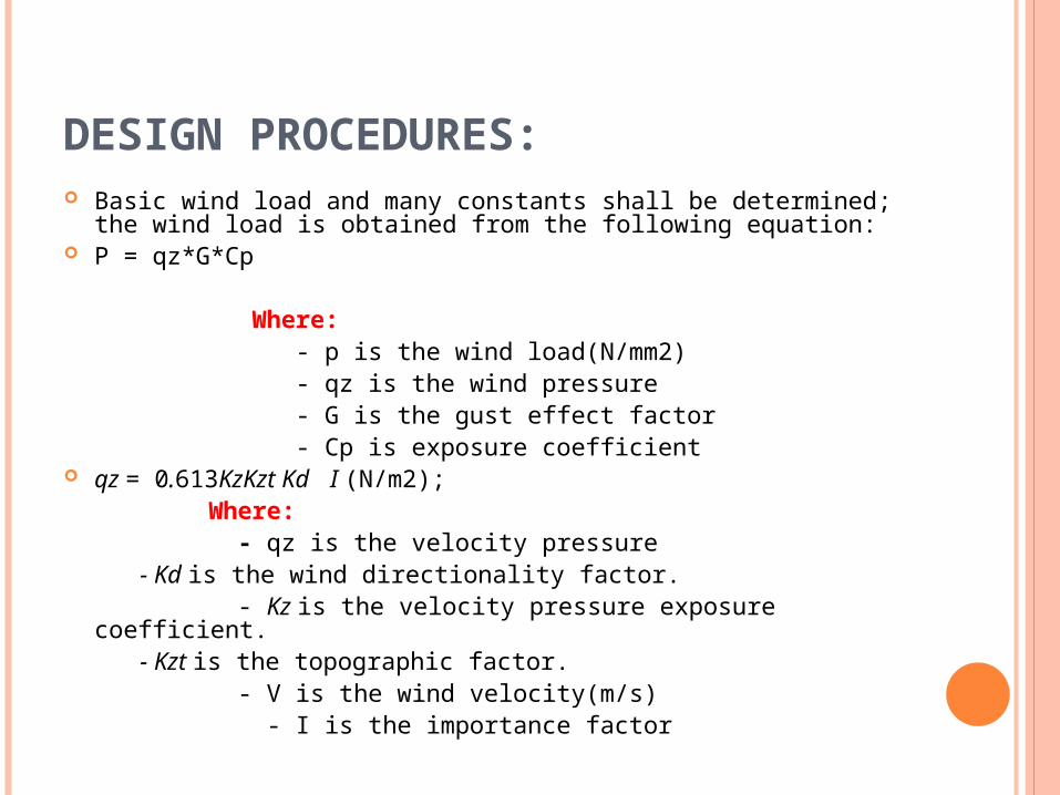
DESIGN PROCEDURES: Basic wind load and many constants shall be determined; the
wind load is obtained from the following equation: P = qz*G*Cp Where: - p is the wind load(N/mm2) - qz is the wind pressure - G is the gust effect factor - Cp is exposure coefficient qz = 0.613KzKzt Kd I (N/m2); Where: - qz is the velocity pressure - Kd is the wind directionality factor. - Kz is the velocity pressure exposure coefficient. - Kzt is the topographic factor. - V is the wind velocity(m/s) - I is the importance factor
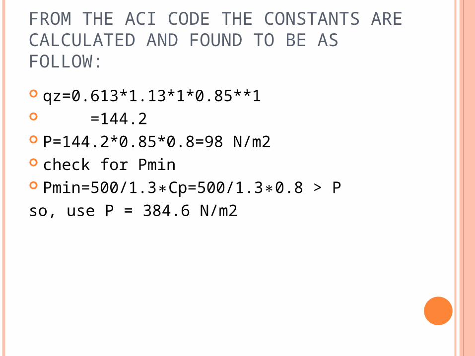
FROM THE ACI CODE THE CONSTANTS ARE CALCULATED AND FOUND TO BE AS FOLLOW:
I = 1.0 (for normal buildings).Kz = 1.33 (box system or shear walls) from
table 6.1 in ACI318-08,KZt = 1 for the Nablus topography.Kd=0.85 in Nablus city.V= 35 mph= 15.65 m/s ( in Nablus city)G=0.85 from ACI tables( in Nablus city) 0.8 for wind wardCp= 0.50 for lee ward 0.70 for side ward 0.70 for roof ward
FROM THE ACI CODE THE CONSTANTS ARE CALCULATED AND FOUND TO BE AS FOLLOW:
qz=0.613*1.13*1*0.85**1 =144.2 P=144.2*0.85*0.8=98 N/m2 check for Pmin Pmin=500/1.3∗Cp=500/1.3∗0.8 > Pso, use P = 384.6 N/m2
SOME INFORMATION ABOUT THE BUILDING:
F`call = (0.3-0.4) F`c = 105 Kg/cm2 Story height= 3.3m 14 stories Residential building F`c for tension= 0.10*F`c for compression=
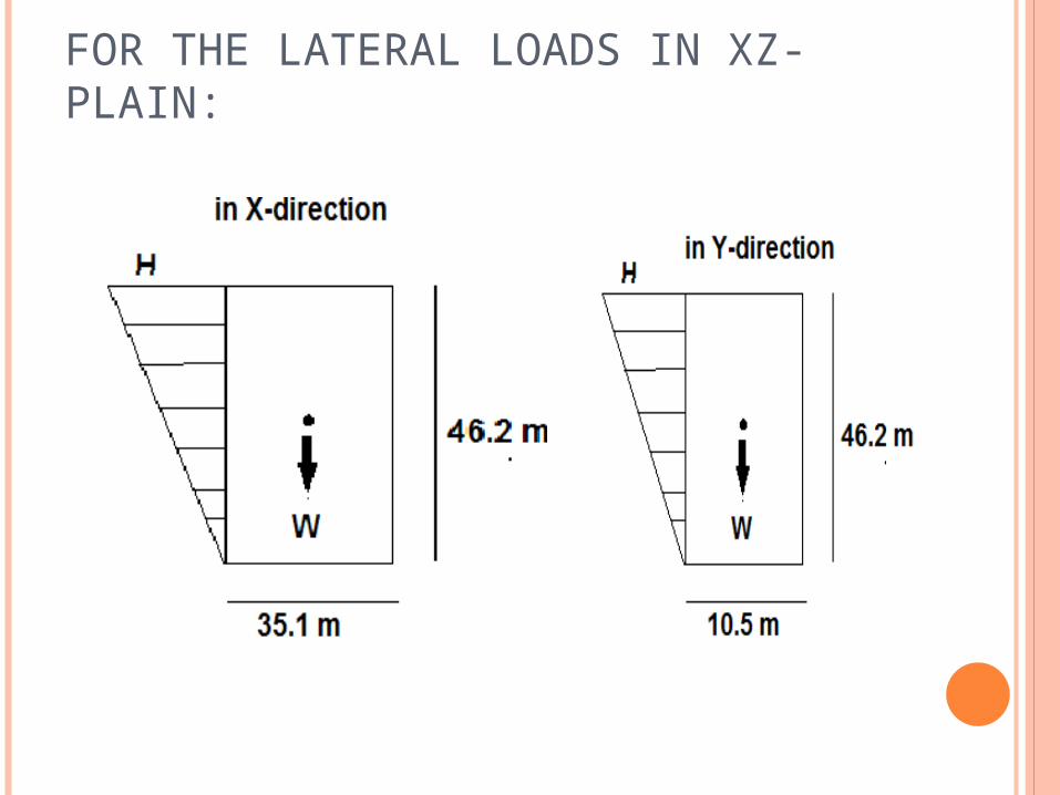
186.76 KN W =0.9*51131.8 = 46018.665 KN H =(186.76/46.5)*1.6= 8.1 KN/m £M= -(0.5*8.1*46.2)*(2*46.2/3) +
46018.7*(35.1/2) =801875.9 KN.m the building weight is sufficient to resist the
wind-load in X-direction.( the same in Y-direction and it is okay)
CHECK THE TORSIONAL EFFECT IN ( XY-PLAN)
Center of mass: X=17 m Y= 5.314 m Center of rigidity:X= 17.11mY= 8.98 m
THE DIFFERENCE BETWEEN THE TWO CENTERS IN THE X-DIRECTION IS SMALL, BUT IN Y-DIRECTION IS LARGE, SO A SAMPLE CALCULATION WILL BE MADE ON THE SHEAR WALL NUMBER 2 IN THE Y-DIRECTION.
e = 8.97-5.31 = 3.66 m V= 0.385*10.5*46.2= 186.76 KN MT =V*e MT = 3.66*186.76= 683.55 KN.m J =4355 KN.m2
F= ( 68.76/2.31) = 29.77 KN/ = 0.29 Kg/ < 10.5 Kg/ the wind-load effect is very small so it can be neglected
CHAPTER SIX: ANALYSIS FOR SEISMIC FORCE USING UBC97 CODE
Seismic Forces- Methods of analysis: Equivalent static method: Dynamic analysis
Response spectrum analysis Time history analysis
SELECTION OF ANALYSIS METHOD
Static method: The static lateral force procedure of Section 1630 may be used for the following structures:
a. All structures, regular or irregular, in Seismic Zone 1 and in Occupancy Categories 4 and 5 in Seismic Zone 2.
b. Regular structures under 73m in height with lateral force resistance provided by systems listed in Table 7-E.
c. Irregular structures not more than five stories or 20m in height.
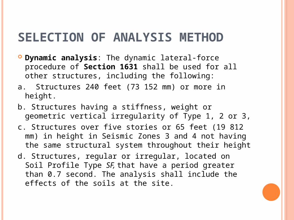
SELECTION OF ANALYSIS METHOD Dynamic analysis: The dynamic lateral-force
procedure of Section 1631 shall be used for all other structures, including the following:
a. Structures 240 feet (73 152 mm) or more in height.
b. Structures having a stiffness, weight or geometric vertical irregularity of Type 1, 2 or 3,
c. Structures over five stories or 65 feet (19 812 mm) in height in Seismic Zones 3 and 4 not having the same structural system throughout their height
d. Structures, regular or irregular, located on Soil Profile Type SF, that have a period greater than 0.7 second. The analysis shall include the effects of the soils at the site.
EQUIVALENT LATERAL FORCE METHOD (STATIC METHOD)- UBC 97 The total design base shear in a given direction shall be
determined from the following formula:
UBC97 30-4
The total design base shear need not exceed the following:
UBC97 30-5
The total design base shear shall not be less than the following:
UBC97 30-6
EQUIVALENT LATERAL FORCE METHOD (STATIC METHOD)- UBC 97
Where: Z= seismic zone factor, Table 7-A I= importance factor, R= numerical coefficient representative of the inherent over
strength and global ductility capacity of lateral- force- resisting systems, Table 7-E
Ca= acceleration seismic coefficient, Table 7-C Cv= velocity seismic coefficient, Table 7-D W= the total dead load and applicable portions of other loads
listed below: 1. In storage and warehouse occupancies, a minimum of 25% of
the floor live load shall be applicable 2. Design snow loads of 1.5kN/m2 or less need not be included.
Where design snow loads exceed 1.5 kN/m2, the design snow load shall be
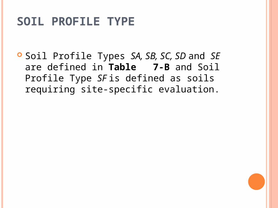
SOIL PROFILE TYPE
Soil Profile Types SA, SB, SC, SD and SE are defined in Table 7-B and Soil Profile Type SF is defined as soils requiring site-specific evaluation.
STRUCTURAL PERIOD
Method A The period, T is given by:
hn= height of structure in meters Ct= factor given by:
Ct=0.0853 for steel moment resisting frames Ct= 0.0731 for reinforced concrete moment resisting
frames and eccentrically braced frames Ct=0.0488 for all other buildings
- T= is the basic natural period of a simple one degree of freedom system which is the time required to complete one whole cycle during dynamic loading
STRUCTURAL PERIOD
Method B:The fundamental period T may be calculated using the
structural properties and deformational characteristics of the resisting elements.
Where: Mi= the mass of the building at the level i = the deflection of the level i, calculated using the applied
lateral forces Fi= the lateral force applied on the level i
SITE AND THE BUILDING INFORMATION:
Number of stories = 14. Story height= 3.3 m. Materials: concrete cylinder compressive strength at 28
days, f’c= 28 𝑀𝑃𝑎 -Steel yield strength, =420 𝑓𝑦 𝑀𝑃𝑎 Soil: rock, Sb type in accordance with UBC 97 provisions. All columns are square with side length equals to 650
mm. All beams are 400 mm section width and 500mm total
thickness. The slab is two way solid slab of 200 mm thickness. External shear walls thickness is 300 mm, and the
internal are 200 mm wide Shear walls weight =25 KN/m.
SITE AND THE BUILDING INFORMATION: The live load is 3 kN/m2 – office and residential building. The superimposed dead load is 3.36 kN/m2. The perimeter wall weight is 21 kN/m. Importance factor (I) =1. Zone factor ( )=0.2, {2B} UBC 97𝑍 𝐶𝑎=0.20, =0.2. 𝐶𝑣 Sizes of all columns in upper floors are kept the same. The floor diaphragms are assumed to be rigid. Lateral-force-resisting system is: Duel systems(4.1.c) Location of building Nablus city . Earthquake load as…..UBC97
SEISMIC LOAD According to Uniform Building Code (UBC97), the seismic
coefficients Ca=0.20, Cv=0.20.
THE MODIFIED PLANE OF THE BUILDINGTO REDUCE THE ECCENTRICITY
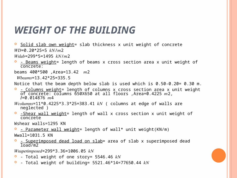
WEIGHT OF THE BUILDING Solid slab own weight= slab thickness x unit weight of concrete 𝑊𝐷=0.20*25=5 / 2 𝑘𝑁 𝑚𝑊𝑠𝑙𝑎𝑏=299*5=1495 / 2 𝑘𝑁 𝑚 - Beams weight= length of beams x cross section area x unit weight of
concrete: beams 400*500 ,Area=13.42 2𝑚 𝑊𝑏𝑒𝑎𝑚𝑠=13.42*25=335.5 Notice that the beam depth below slab is used which is 0.50-0.20= 0.30 m. - Columns weight= length of columns x cross section area x unit weight of
concrete: columns 650X650 at all floors ,Area=0.4225 2, =0.014876 4 𝑚 𝐼 𝑚𝑊𝑐𝑜𝑙𝑢𝑚𝑛𝑠=11*0.4225*3.3*25=383.41 ( columns at edge of walls are 𝑘𝑁neglected )
-Shear wall weight= length of wall x cross section x unit weight of concreteWshear walls=1295 KN - Parameter wall weight= length of wall* unit weight(KN/m)Wwall=1031.5 KN - Superimposed dead load on slab= area of slab x superimposed dead
load/m2 𝑊𝑠𝑢𝑝𝑒𝑟𝑖𝑚𝑝𝑜𝑠𝑒𝑑=299*3.36=1006.05 𝑘𝑁 - Total weight of one story= 5546.46 𝑘𝑁 - Total weight of building= 5521.46*14=77650.44 𝑘𝑁
THE STRUCTURE PERIOD
ƩIx=27.9075 m4
THE STRUCTURE PERIOD
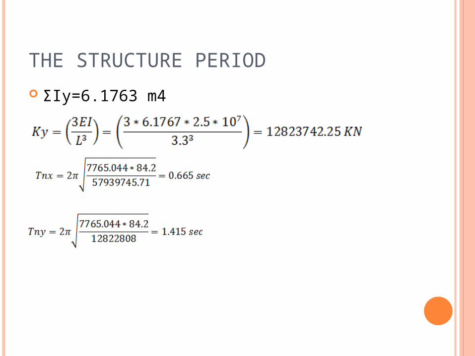
ƩIy=6.1763 m4
BASE SHEAR IN Y-DIRECTION
R= 6.5 from UBC97 Table16-N (Duel system 4.1.c).
- The base shear, V, need not exceed
- The base shear shall not be less than 𝑉=0.11𝐶𝑎𝐼𝑊 𝑉=0.11*0.20*1*𝑊=0.022𝑊 > 0.0217𝑊 So, total base shear will be 𝑉=0.022 *7756.044= 1700.6 KN
BASE SHEAR IN Y-DIRECTION
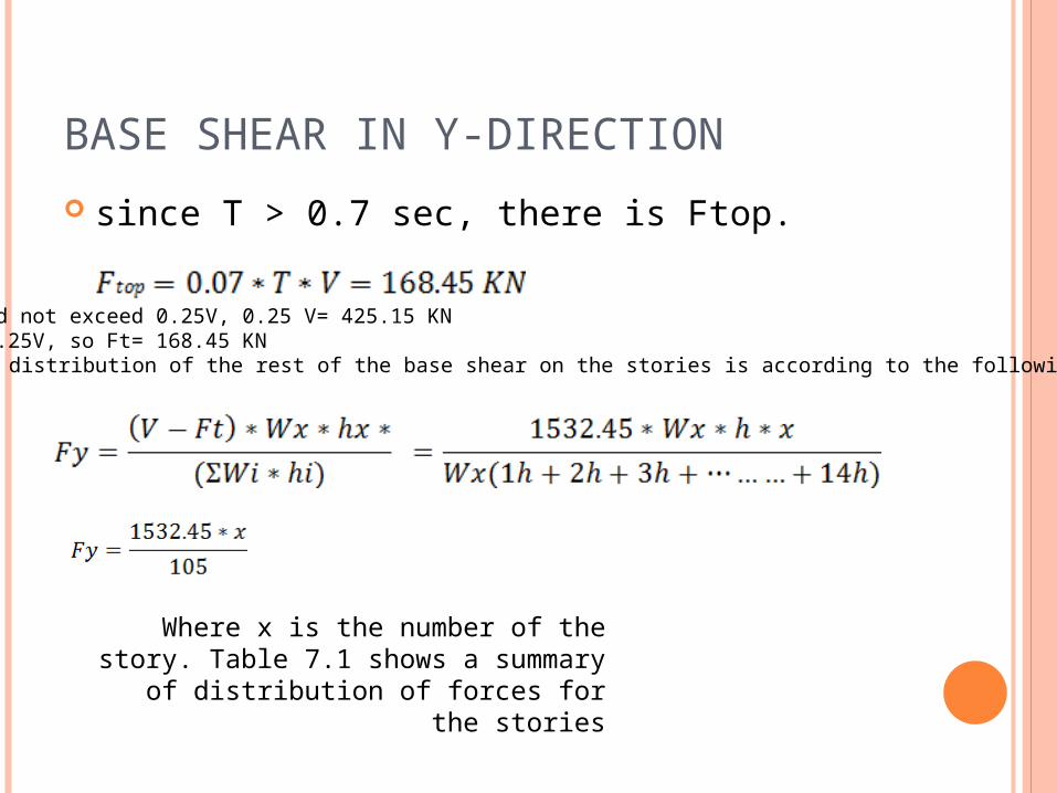
since T > 0.7 sec, there is Ftop.
Ftop need not exceed 0.25V, 0.25 V= 425.15 KNFtop < 0.25V, so Ft= 168.45 KNand the distribution of the rest of the base shear on the stories is according to the following equation:
Where x is the number of the story. Table 7.1 shows a summary of
distribution of forces for the stories
TABLE 7.1: DISTRIBUTION OF FORCES TO STORIES
CENTER OF RIGIDITY
CALCULATION OF ECCENTRICITY DUE TO SEISMIC FORCES:
center of mass(CM)X=17.43 my=5.25 m center of rigidity (CR)X=18.187 mY=6.8177 m emax= eo + e2 emin= eo - e2 eo: the real eccentricity is the distance between the CR( center of stiffness and the
CM and center of mass). 0e eo: accidental eccentricity e2= accidental eccentricity e2 =0.05*L - L: the floor dimension perpendicular to the direction of the seismic action. eo=18.187 -17.43= 0.757 m e2= 0.05*35.1= 1.755 m emax=1.755 +0.757= 2.512 m emin= -0.998 m
HORIZONTAL DISTRIBUTION OF STORY SHEAR TO THE WALLS The distribution of the total seismic load, to walls will be in
proportion to their rigidities.. The flexural resistance of walls with respect to their weak axes may be neglected in lateral load analysis. Table 7.4 summarizes the force distribution to the columns and walls in y direction.
the table 7.3: shows (Km, Kp, dm and dp) for the shear walls.
Where: - 𝑉𝑚: The shear force of the structural walls m , parallel to the direction of the seismic action. - 𝑉𝑝: The shear force of the structural walls p, perpendicular to the direction of the seismic action. - dm,dp: The distance from the centers of gravity of the structural walls m and p to the considered center of rigidity.- 𝑘𝑡: The torsion rigidity of the considered level.-𝑘𝑝: The translation rigidity of the considered wall. -K : The total translation rigidity of the considered level
TABLE 7.3: DISTRIBUTION OF FORCES TO SHEAR WALL AT EACH STORY (V IS IN KN
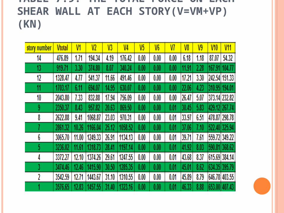
TABLE 7.5: THE TOTAL FORCE ON EACH SHEAR WALL AT EACH STORY (KN) ( V=VM+VP)
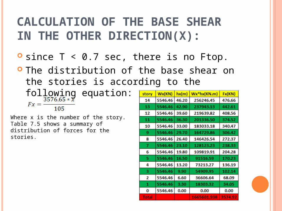
CALCULATION OF THE BASE SHEAR IN THE OTHER DIRECTION(X):
The same procedures as in Y-direction
The base shear, V in the y-direction will be: R= 6.5 from UBC97 Table16-N (Duel system 4.1.c
The base shear, V, need not exceed
- The base shear shall not be less than 𝑉=0.11𝐶𝑎𝐼𝑊 𝑉=0.11*0.20*1*𝑊=0.022𝑊 < 0.046 𝑊
So, total base shear will be 𝑉=0.046 *7756.044= 3576.65 KN
CALCULATION OF THE BASE SHEAR IN THE OTHER DIRECTION(X):
since T < 0.7 sec, there is no Ftop. The distribution of the base shear on the
stories is according to the following equation:
Where x is the number of the story. Table 7.5 shows a summary of distribution of forces for the stories.
CALCULATION DO ECCENTRICITY DUE TO SEISMIC FORCES:CENTER OF MASS(CM) center of mass(CM)X=17.43 my=5.25 m center of rigidity (CR)X=18.187 mY=6.8177 m emax= eo + e2 emin= eo - e2 eo: the real eccentricity is the distance between the CR( center of stiffness and the
CM and center of mass). 0e eo: accidental eccentricity e2= accidental eccentricity e2 =0.05*L - L: the floor dimension perpendicular to the direction of the seismic action. eo=6.8177-5.25 =1.4617 m e2= 0.05*10.5= 0.525 m emax=1.4117+0.525=1.9867 m emin= 0.8867 m
HORIZONTAL DISTRIBUTION OF STORY SHEAR TO WALLS
Table7.7:( Km(KN), Kp(KN), dm(m), dp(m)) for the shear walls
TABLE 7.8: DISTRIBUTION OF FORCES TO SHEAR WALL AT EACH STORY (V IS IN KN)
TABLE 7.9: THE TOTAL FORCE ON EACH SHEAR WALL AT EACH STORY(V=VM+VP) (KN)
TABLES USED IN THE ANALYSIS:
TABLES USED IN THE ANALYSIS:
TABLES USED IN THE ANALYSIS:
CHAPTER 7- 3D MODELING Structural System used: In this project, 3D modeling will be made for the
structure, and two-way slab with beams will be used as the structural system, since the project will be analyzed and designed to resist the earthquakes.
No analysis will be made in this chapter, only the modeling.
By using 2D modeling on SAP2000 and applying many thicknesses to obtain an economical one, it was found the following:
Slab thickness= 20 cm- Beams are 40*50 cm- and for the modifiers for SAP: - Beam=0.35 - Slab=0.25 - Column=0.70
STRUCTURAL MATERIALS: 1) Concrete :The main material used in the structural is the
concrete: * The cylindrical compressive strength after 28
days, f’c =24 MPa (B300) for slabs and beams.* Modulus of elasticity ,E= 2.3* f’c = 28 MPa (B350) for columns.* Modulus of elasticity, E=2.49**Unit weight is 25 KN/ 2) Steel:*The Steel yield strength used for steel
reinforcement is 420 MPa*The modulus of elasticity is 2.04* MPa
3D-MODELING ON SAP 2000
SAP2000 RESULTS Equilibrium check: The final check in the model is Check local equilibrium by comparing the
results of moments for beams and slabs from structural three-dimensional model using SAP 2000 and hand calculation.
the loads from SAP as shown on the following table
Table 7.1: the loads resulted from SAP
Support reactions: - Dead (own weight) = 49265.037 KN -Superimposed dead= 14084.717 KN - Live= 12575.64- Parameter wall weight= 14371.363 KN - Dead+ superimposed dead+ parameter wall= 77721.117 KN (77650.44 KN by hand calculations))The mass and support reactions are equal to that in hand calculations
SAP2000 RESULTS
Periods: Table 7.2 : Structure periods
First mode- movement in y- direction The period in Y-direction in hand calculations is 1.415seconds (UBC 97)The period in X-direction in hand calculation= 0.665 seconds (UBC 97)
EQUIVALENT STATIC METHOD: in this project, the base shear will be calculated by the
equivalent static method using two values for the period: 1- the period produced from the hand calculation( Tnx= 0.665 sec and Tny=
1.415 sec) 2- and the period produced by SAP 2000 (Tnx=1.533 sec and Tny=1.83 sec)
1) The first period- the manual one
Base shear resulted from SAP 2000 using the UBC
97 code.(using the periods that are calculated
manually)
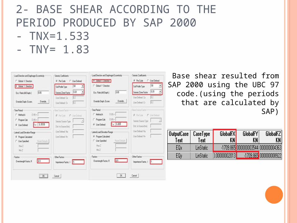
2- BASE SHEAR ACCORDING TO THE PERIOD PRODUCED BY SAP 2000- TNX=1.533- TNY= 1.83
Base shear resulted from SAP 2000 using the UBC 97 code.
(using the periods that are calculated by SAP)
COMMENTS ON THE RESULTS:
In order to have the same results of the hand calculation and the equivalent static method, the assumptions that have been made to the hand calculation must meets the equivalent static method conditions.
In hand calculation, we assumed that the building is moving 100% in the X-direction to calculate the Tnx. and the same assumption for y-direction.
but SAP 200 results show that the X-mode has 0.36 model participating mass ratio and Y-mode has 0.66 model participating mass ratio. this is opposite to the assumption, so the equivalent static method give results with a high percentage of error
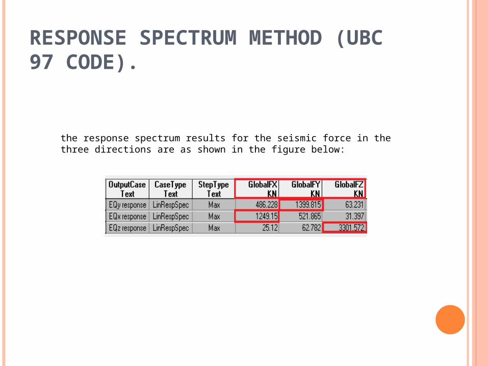
RESPONSE SPECTRUM METHOD (UBC 97 CODE).
the main direction of the seismic force is X-direction( U1)
the main direction of the seismic force is Y-direction (U2)
the main direction of the seismic force is Z-direction (U3)
STRUCTURE PERIODS
The modes periods and their participating mass ratios( for 150 modes)
RESPONSE SPECTRUM METHOD (UBC 97 CODE).
the response spectrum results for the seismic force in the three directions are as shown in the figure below:
ANALYSIS AND DESIGN OF SHEAR WALLS
500 mm
SLw/5
3h
ANALYSIS AND DESIGN OF SHEAR WALLS find the concrete strength to resist shear for all shear
walls Find the Vu from SAP, on each shear wall:
ANALYSIS AND DESIGN OF SHEAR WALLS
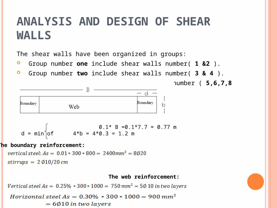
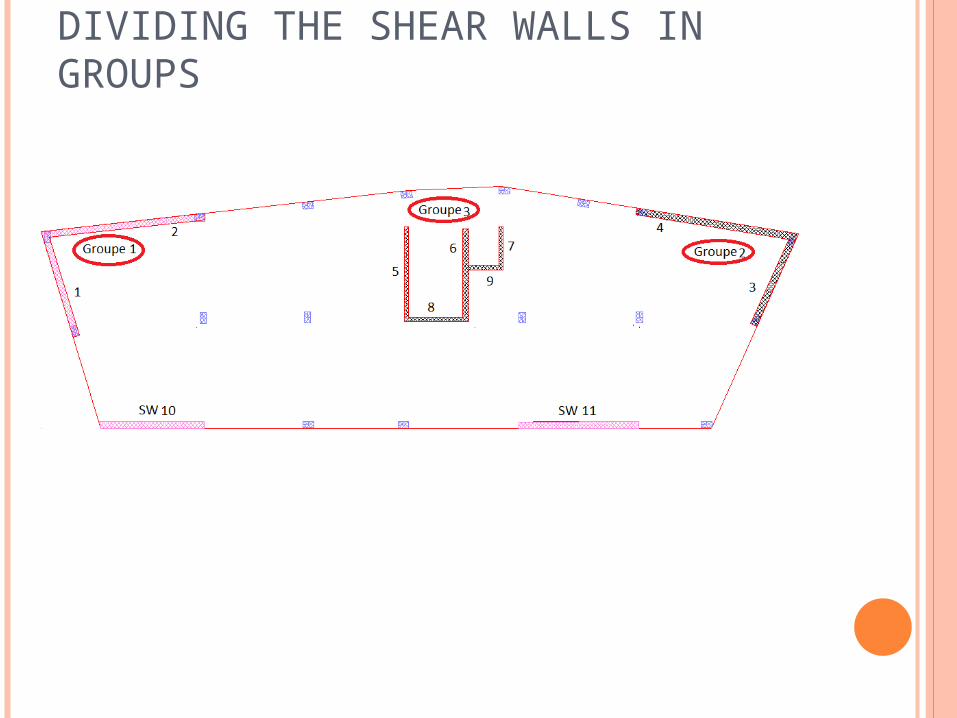
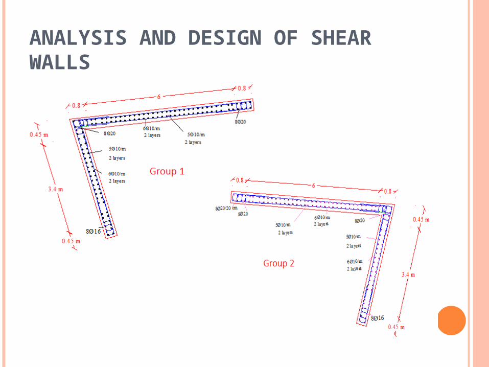
The shear walls have been organized in groups: Group number one include shear walls number( 1 &2 ). Group number two include shear walls number( 3 & 4 ). Group number three include shear walls number ( 5,6,7,8 and 9).
0.1* B =0.1*7.7 = 0.77 md = min of 4*b = 4*0.3 = 1.2 m
The boundary reinforcement:
The web reinforcement:
DIVIDING THE SHEAR WALLS IN GROUPS
ANALYSIS AND DESIGN OF SHEAR WALLS
ANALYSIS AND DESIGN OF SHEAR WALLS
WINDOW IN THE FOLLOWING SHEAR WALLS:(1, 2, 3, 4, 10 AND 11), SPECIAL REINFORCEMENT SHALL BE PROVIDED AS FOLLOW:
WINDOWS IN SHEAR WALLS
in the earlier mentioned shear walls, use the following reinforcement:Av= 0.0015*bw*S1Avh=0.0025*bw*S2S1={(d/3), 500} mmS2={(d/3), 500} mm
TIE BEAM DESIGN
the main idea to use tie beam in structure is decrease deferential settlement of the footing due to loads transfer from other elements of structure
Beam ID Section (mm) Effective depth (mm)Tie beam 500*300 440
SAP 2000 results: Bending moment diagram:
Beam ID Section(mm)
d(mm) Length (m)
(1-2) 500*300 440 5.7
Maximum positive moment = 21.3 KN.m
)
Use 3
SHEAR FORCE DIAGRAM:
Design tie beam for shear: Ultimate shear load = 15 KN Ultimate Shear load at critical section = 13.9
Ramp is a flat supporting surface tilted at an angle, with one end higher than the other
elements Section(mm)Beam 500*250slab One way solid (h = 25cm)
MODIFICATION FACTORS FOR STRUCTURAL ELEMENTS:
Beam modification factor Slab modification factor
In this figure show the bending moment diagram for ramp slab .
Design ramp slab:Slab thickness 25 cm (one way solid slab)Design slab (A-B) for flexure:
Use area of steel As (min) = 660 mm2
Slab ID Longitudinal reinforcementNegative moment Positive momentSlab (A-B) 6 /1 m 6 /1 mSlab (B-C) 6 /1 m 6 /1 mSlab (C-D) 6 /1 m 6 /1 mSlab (D-E) 6 /1 m 6 /1 mSlab (E-F) 6 /1 m 6 /1 m
Beam Design:Bending moment in the beam duo to load transfer from ramp slab is very small, so that beam design must be depends on the minimum design case:
Section of beam (50*25 cm)
As (min) = 0.0033*500*200 = 300 mm2
Use 3
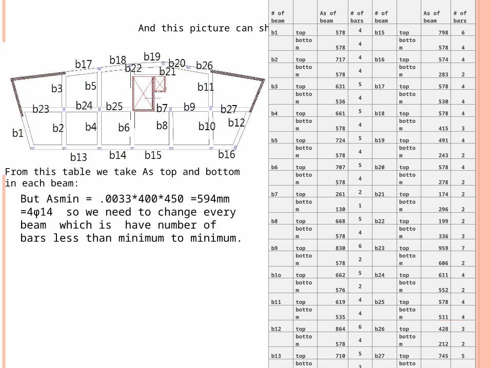
DESIGN BEAMS: From SAP we design beams and take As and this picture can show that
And this picture can show beam number:
From this table we take As top and bottom in each beam:
# of beam
As of beam
# of bars
# of beam
As of beam
# of bars
b1 top 578 4 b15 top 798 6
bottom 578 4 bottom 578 4
b2 top 717 4 b16 top 574 4
bottom 578 4 bottom 283 2
b3 top 631 5 b17 top 578 4
bottom 536 4 bottom 530 4
b4 top 661 5 b18 top 578 4
bottom 578 4 bottom 415 3
b5 top 724 5 b19 top 491 4
bottom 578 4 bottom 243 2
b6 top 707 5 b20 top 578 4
bottom 578 4 bottom 278 2
b7 top 261 2 b21 top 174 2
bottom 130 1 bottom 296 2
b8 top 668 5 b22 top 199 2
bottom 578 4 bottom 336 3
b9 top 830 6 b23 top 959 7
bottom 578 2 bottom 606 2
b1o top 662 5 b24 top 611 4
bottom 576 2 bottom 552 2
b11 top 619 4 b25 top 578 4
bottom 535 4 bottom 511 4
b12 top 864 6 b26 top 428 3
bottom 578 4 bottom 212 2
b13 top 710 5 b27 top 745 5
bottom 522 3 bottom 578 4
b14 top 589 4
bottom 412 3
But Asmin = .0033*400*450 =594mm =4φ14 so we need to change every beam which is have number of bars less than minimum to minimum.
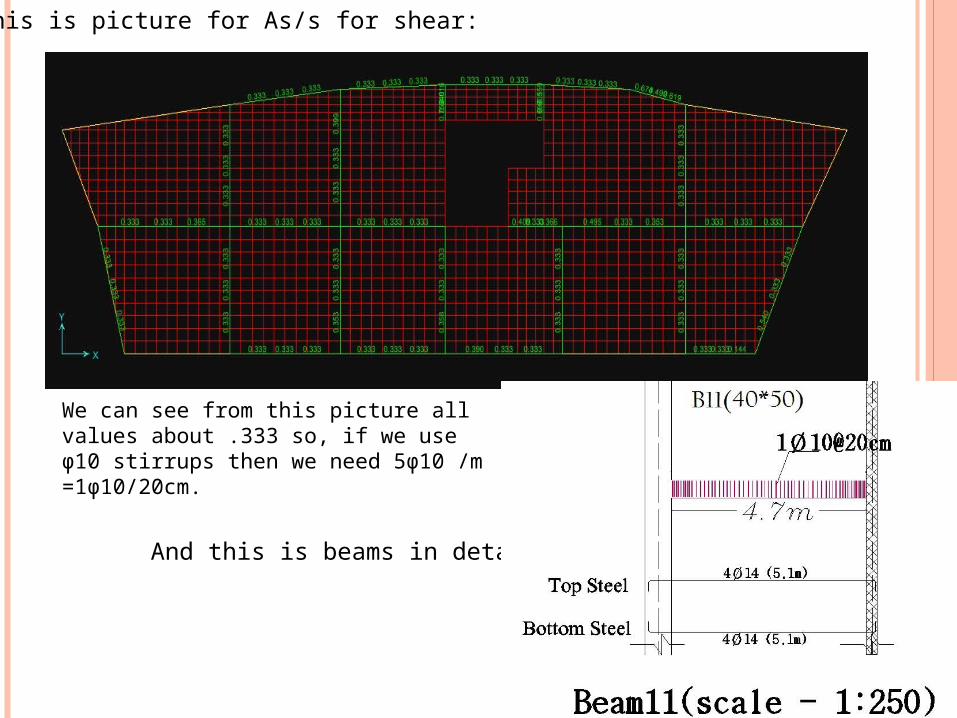
And this is picture for As/s for shear:
We can see from this picture all values about .333 so, if we use φ10 stirrups then we need 5φ10 /m =1φ10/20cm.
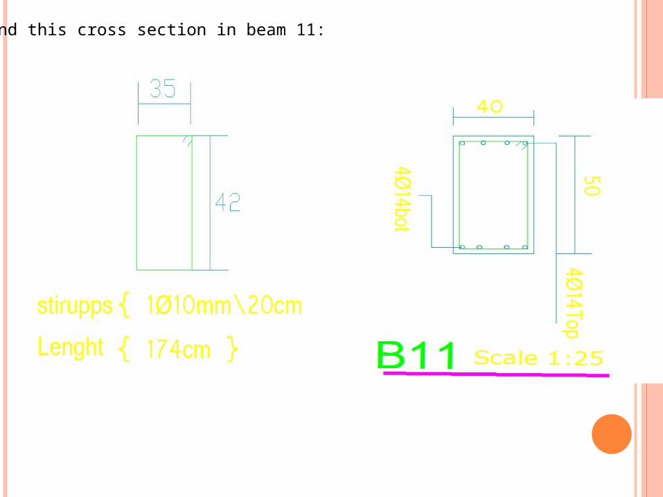
And this is beams in detail
And this cross section in beam 11:
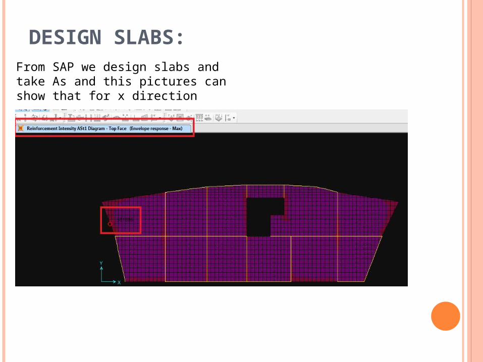
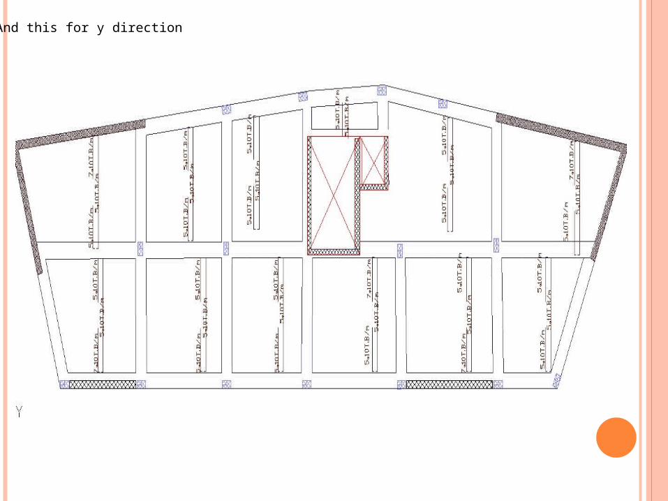
DESIGN SLABS:From SAP we design slabs and take As and this pictures can show that for x direction
bottom face
but ASmin = 360mm2/m and this more than 215mm on the bottom face so use Asmin and this is the details in the x direction