A Build-Your-Own Open Source CNC Milling Machine Fabrication and User Manual MHRD – Teaching Learning Centre for Design and Manufacturing Indian Institute of Information Technology for Design and Manufacturing – Kancheepuram, Chennai - 600127
Transcript
A Build-Your-Own
Open Source CNC Milling Machine
Fabrication and User Manual
MHRD – Teaching Learning Centre for Design and Manufacturing
Indian Institute of Information Technology for Design and Manufacturing –
Kancheepuram, Chennai - 600127
MHRD Teaching Learning Centre for Design and Manufacturing
A Build-Your-Own Open Source CNC Milling Machine
Version 2.0, December 2016
Documentation Author
Kamal Prasath Balaji
Guide
Dr. S R Pandian
Project Team
Raja Ganapathi
Kamal Prasath Balaji
For information
Teaching Learning Center for Design and Manufacturing(TLC),
4.1. Arduino CNC controller Pin-out .............................................................................................................. 9 4.2. Stepper Motor signal and power connections ........................................................................................... 9
MHRD Teaching Learning Centre for Design and Manufacturing
MHRD Teaching Learning Centre for Design and Manufacturing
LIST OF TABLES
Table 1. Mechanical Parts List .............................................................................................................. 2 Table 2 Mechanical Hardware Assembly ............................................................................................. 5 Table 3 Electrical and Electronics parts list .......................................................................................... 8
MHRD Teaching Learning Centre for Design and Manufacturing
1
CNC Milling Machine
1. Introduction
CNC Milling Machines are widely used in manufacturing sectors. It is mandatory to
teach the technology in Polytechnic and engineering colleges. But the problem is to afford same
machines which are developed for industrial applications to educational purpose. Even if an
educational institution poses such machines, every student is not having hands-on experience
because, each student cannot be afforded with industrial standard CNC machine. This DIY
CNC machine will be a good alternative for expensive machines to teach CNC at beginner
level. Because of Open Source tools, this CNC can be developed approximately at 5% of basic
commercial product in the market. And, students can have their working experience with CNC
machines individually. Students can also develop these machine by their own.
This document is partly influenced by the wiki pages of Zen Tool Works
(http://www.zentoolworks.com/index.php?cPath=14). The document briefs about building of
DIY CNC Milling machine with Open Source software. The DIY CNC Milling machine shown
in Fig.1 is fabricated with PVC sheets as main raw material for its frame. Each part is listed
with its design details for fabrication. Few OEM products are also used such as guide rod,
linear bearings, couplers etc. Standard electronics parts like stepper driver, controller board,
Power supply, emergency switches are standardly chosen for their easy availability in market.
Fig 1. CNC Milling machine- setup
MHRD Teaching Learning Centre for Design and Manufacturing
2
2. Hardware
2.1. Hardware Requirements
Hardware parts of the machine are combined with fabricated as well as few
commercially available products. Main frame of the machine is fabricated using plain 8mm
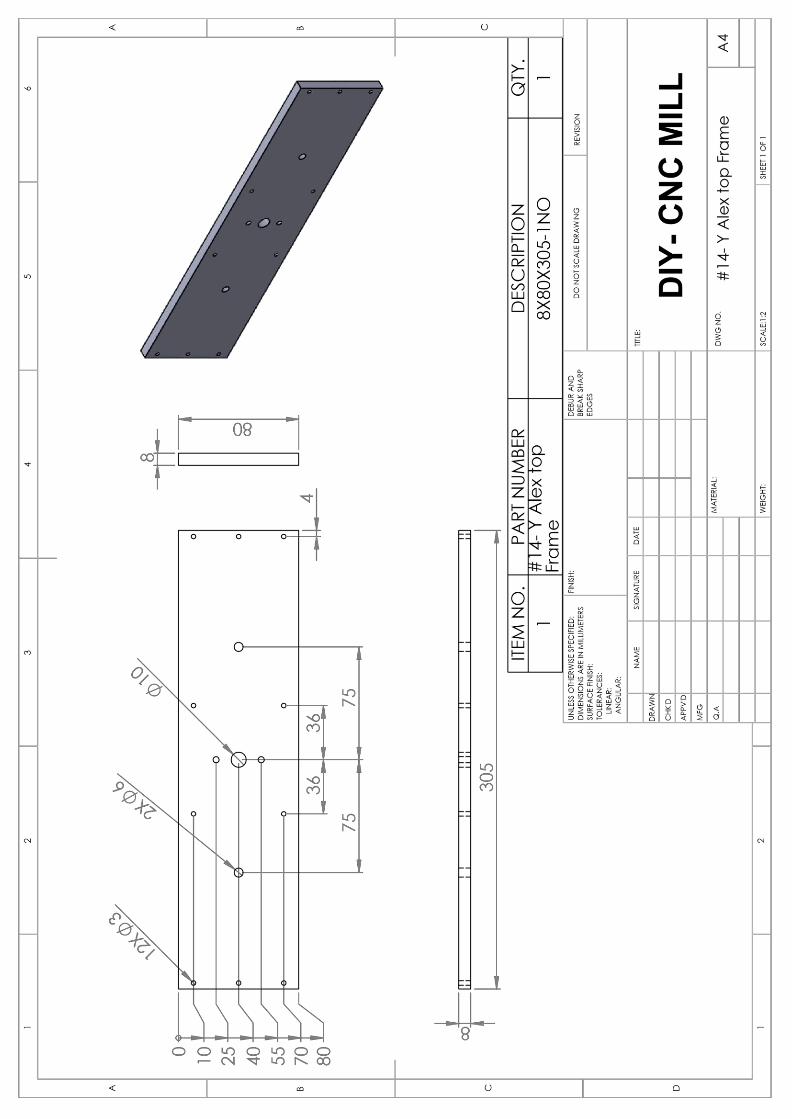
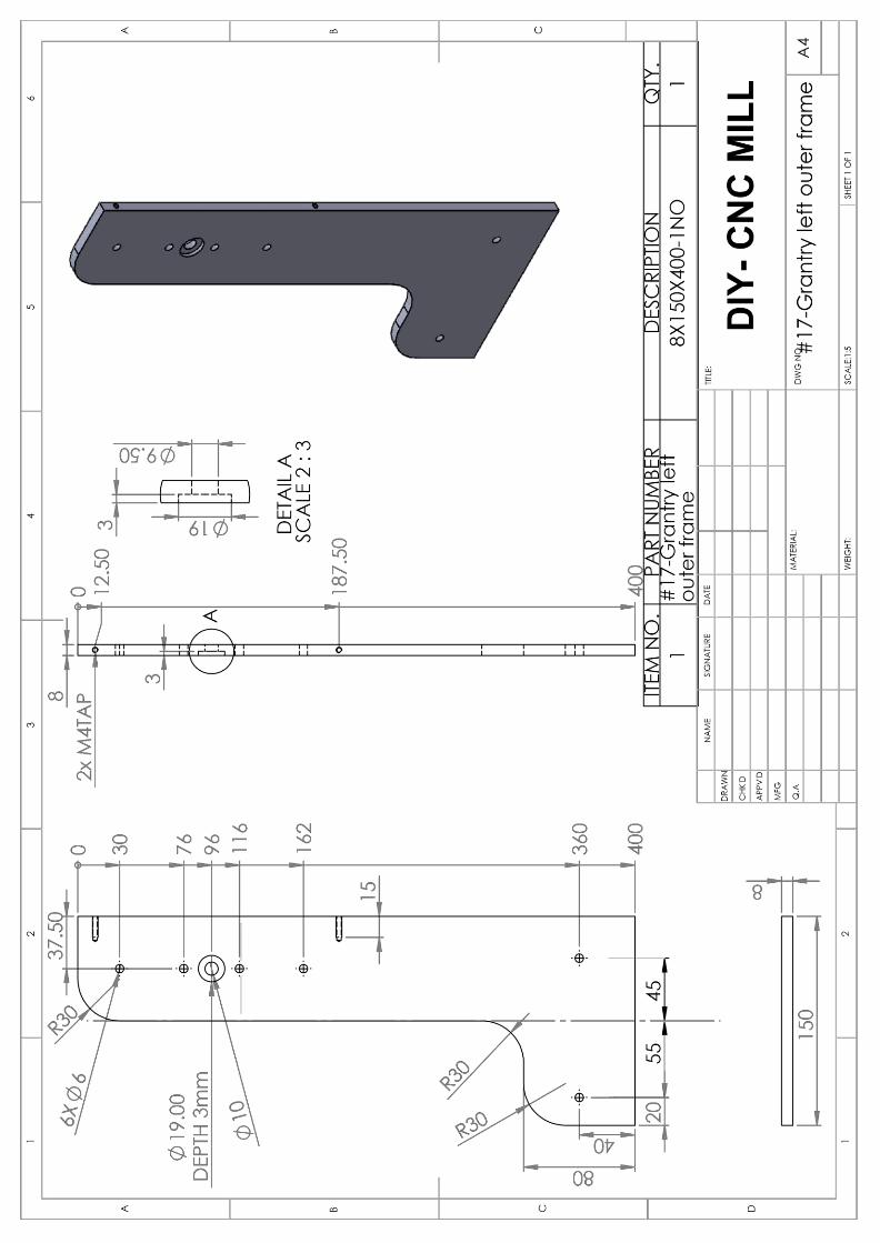
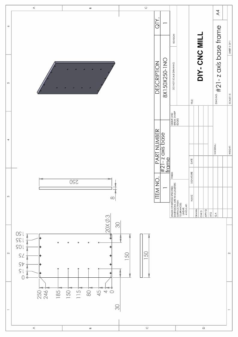
PVC sheet as per design. Design file of each component is attached in Appendix-1. Following
table contains list of components required for CNC Milling machine fabrication.
Table 1. Mechanical Parts List
Mechanical Parts List
3 x Stepper motors – NEMA 17
3 x Motor Shaft Flex Coupling
6 x End Support Ball Bearing
3 x M8 flange Nut
Cad Model: #00 screw rod nut
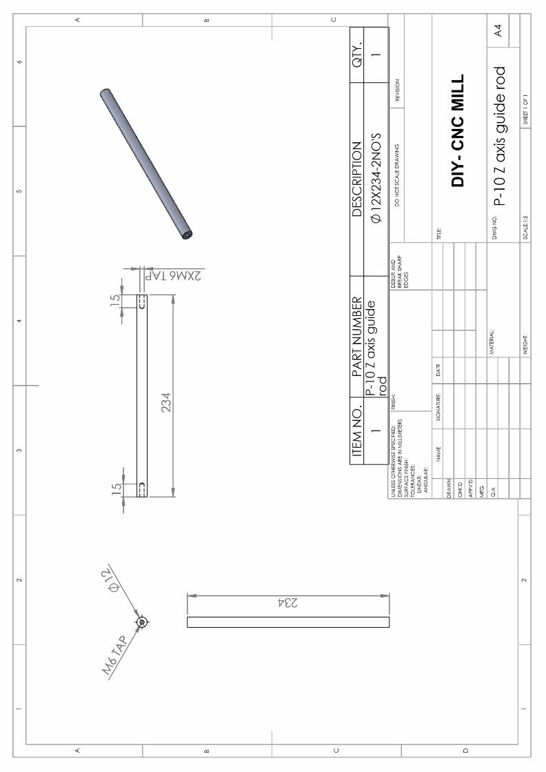
6 x X, Y, Z Axis Guide Rod
Cad Model:
p-08 x axis guide rod
p-08 y axis guide rod
P-10 Z axis guide rod
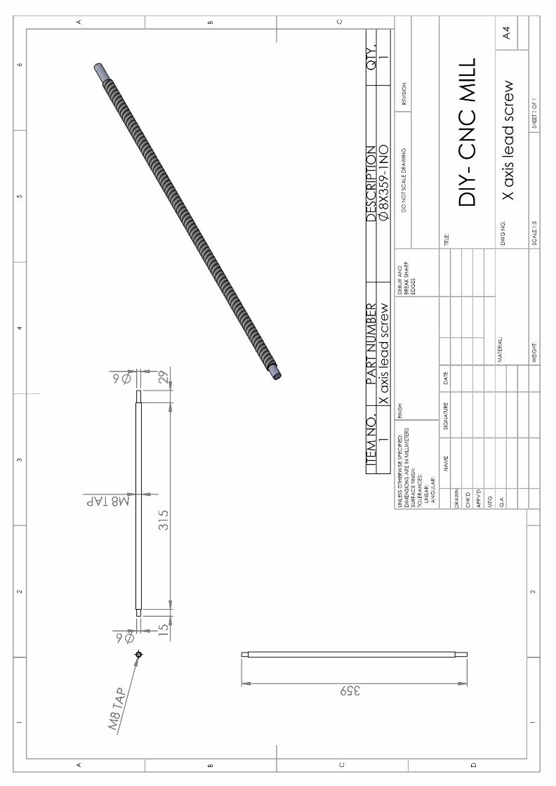
3 x X, Y, Z Axis Lead Screw
Cad Model:
X axis lead screw
Y axis lead screw
P-11 Z axis lead screw
MHRD Teaching Learning Centre for Design and Manufacturing
3
12 x LM 12UU Linear Bearing
3 x #02 – Stepper Motor Base
4 x #03 – End Bearing Block
#04 – Z Axis Upper Support
#05 – Z Axis Lower Support
#06 – Gantry Right Support
#07 – Gantry Left Support
#08 – Z Bottom frame
#09 – Z Top Frame
#10 – Y Axis Higher Support
#11 – Y Axis Lower Support
6 x #12 – Motor Support Block
MHRD Teaching Learning Centre for Design and Manufacturing
4
#13 – Y Axis Lower Frame
#14 – Y Axis Top Frame
#15 – Y Axis Side Frame
#16 – Tool Base
#17, #18 - Gantry Left Inner and Outer Frame
#19, #20 - Gantry Right Inner and Outer Frame.
#21 – Z Axis Base Frame
#22 Gantry Back Enforce Frame
#23 – Working Table
MHRD Teaching Learning Centre for Design and Manufacturing
5
2.2. Hardware Assembly
Following table contains instructions for assembling mechanical parts which are
fabricated as given in design documents. All assembly screws are Allen head type screws.
Table 2 Mechanical Hardware Assembly
Here are the main components for assembling Y axis
Assembling of Bearing to bearing block
Bearing Block
Lead screw nut assembly with moving carrier
Y axis lead screw, nut, linear bearing and guide
rod assembly
Y axis assembly exploded
Y axis assembly
MHRD Teaching Learning Centre for Design and Manufacturing
6
X axis assembly with column
Z axis assembly
MHRD Teaching Learning Centre for Design and Manufacturing
7
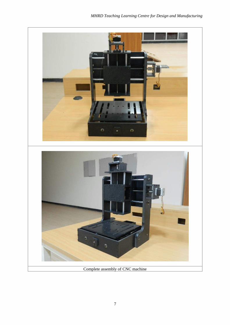
Complete assembly of CNC machine
MHRD Teaching Learning Centre for Design and Manufacturing
8
3. Electrical and Electronics parts list Required electrical and electronics components listed in following table
Table 3 Electrical and Electronics parts list
Electrical and Electronics parts list
Arduino UNO x1
NEMA 17 Stepper Motor x3
Stepper Motor driver x3
Emergency Stop Button x1
High Speed 24V spindle motor x1
24V, 10A SMPS x1
Limit Switch x 3 (optional)
Power Cord for SMPS x1
Red Black Wires for driver power source
4 different color wires for stepper motor
connection
Jumper Wires M-M (minimum 15)
MHRD Teaching Learning Centre for Design and Manufacturing
9
4. Circuit Connection
4.1. Arduino CNC controller Pin-out
Fig 2. Arduino Pin-out Configuration
4.2. Stepper Motor signal and power connections
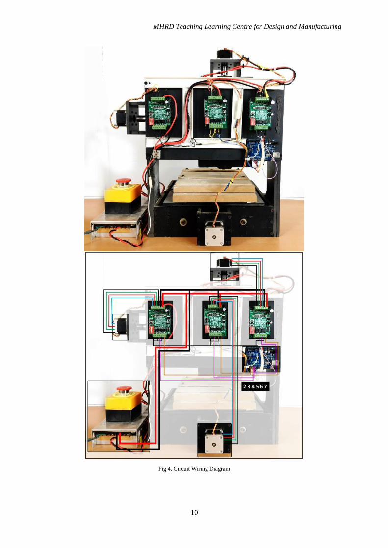
Connect Arduino, stepper driver, stepper motor emergency switch and SMPS as shown in Fig 3.
Fig 3. Schematic Connection Diagram
MHRD Teaching Learning Centre for Design and Manufacturing
10
Fig 4. Circuit Wiring Diagram
MHRD Teaching Learning Centre for Design and Manufacturing
11
5. Software
5.1. Arduino Connection to Computer
Connect Arduino Uno using USB type B to computer/laptop from which machine is needed to
be controlled. Arduino drivers will be installed automatically.
Fig 5. Arduino - Computer Interface
5.1.1 Arduino COM Port Selection
COM port (communication port) is a hardware interface to computer. Each device will have
different software COM port number which can be modified. To upload any program to arduino board,
knowing COM number of that corresponding board is mandatory.
• Windows 7: Click "Start" -> Right click "Computer" -> Select "Manage" -> Select "Device
Manager" from left pane
• In the tree, expand "Ports (COM & LPT)"
• Your Arduino will be the USB Serial Port (COMX), where the “X” represents the COM
number, for example COM6.
• If there are multiple USB serial ports, right click each one and check the manufacturer, the
Arduino will be "FTDI".
Fig 6. COM port selection
MHRD Teaching Learning Centre for Design and Manufacturing
12
5.2. Arduino CNC GRBL file download
GRBL file is pre-complied hex file which include a program that converts Gcode to stepper
motor control signals from Arduino. Download recent version from following link.
https://github.com/grbl/grbl/downloads
5.3. Converting Arduino to CNC controller
Compiled Hex file cannot be loaded directly from Arduino software. It requires another
firmware to load hex file into Arduino. Xloader is used to load HEX file directly to Arduino. Download
Xloader from the link
http://russemotto.com/xloader/
• Open XLoader and select your Arduino's COM port from the drop-down menu on the lower
left.
• Select the appropriate device(Arduino UNO) from the dropdown list titled "Device".
• Check that Xloader set the correct baud rate for the device: 115200 for Uno (ATmega 328).
• Now use the browse button on the top right of the form to browse to your grbl hex file.
• Once your grbl hex file is selected, click "Upload"
Fig 7. Uploading GRBL Hex file to Arduino using Xloader
5.4. Universal G-code Sender
After uploading, Arduino controller will be converted to CNC controller by which Gcode can
be fed directly. Controlling arduino requires another software which communicates serially to arduino
to send signals to Arduino controller. Universal-G-Code-Sender is a cross platform developed in Java.
• UGS Requires to Install/upload Java 8 or later
• Download Universal-G-Code-Sender from the following link
https://github.com/winder/Universal-G-Code-Sender
• Download recent version under Stable builds
• Extract downloaded file and open UniversalGcodeSender.jar file
• Ensure Arduino is connected to computer before opening
• Click on Open button to connect Arduino to computer.
MHRD Teaching Learning Centre for Design and Manufacturing
13
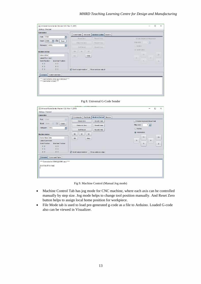
Fig 8. Universal G-Code Sender
Fig 9. Machine Control (Manual Jog mode)
• Machine Control Tab has jog mode for CNC machine, where each axis can be controlled
manually by step size. Jog mode helps to change tool position manually. And Reset Zero
button helps to assign local home position for workpiece.
• File Mode tab is used to load pre-generated g-code as a file to Arduino. Loaded G-code
also can be viewed in Visualizer.
MHRD Teaching Learning Centre for Design and Manufacturing
14
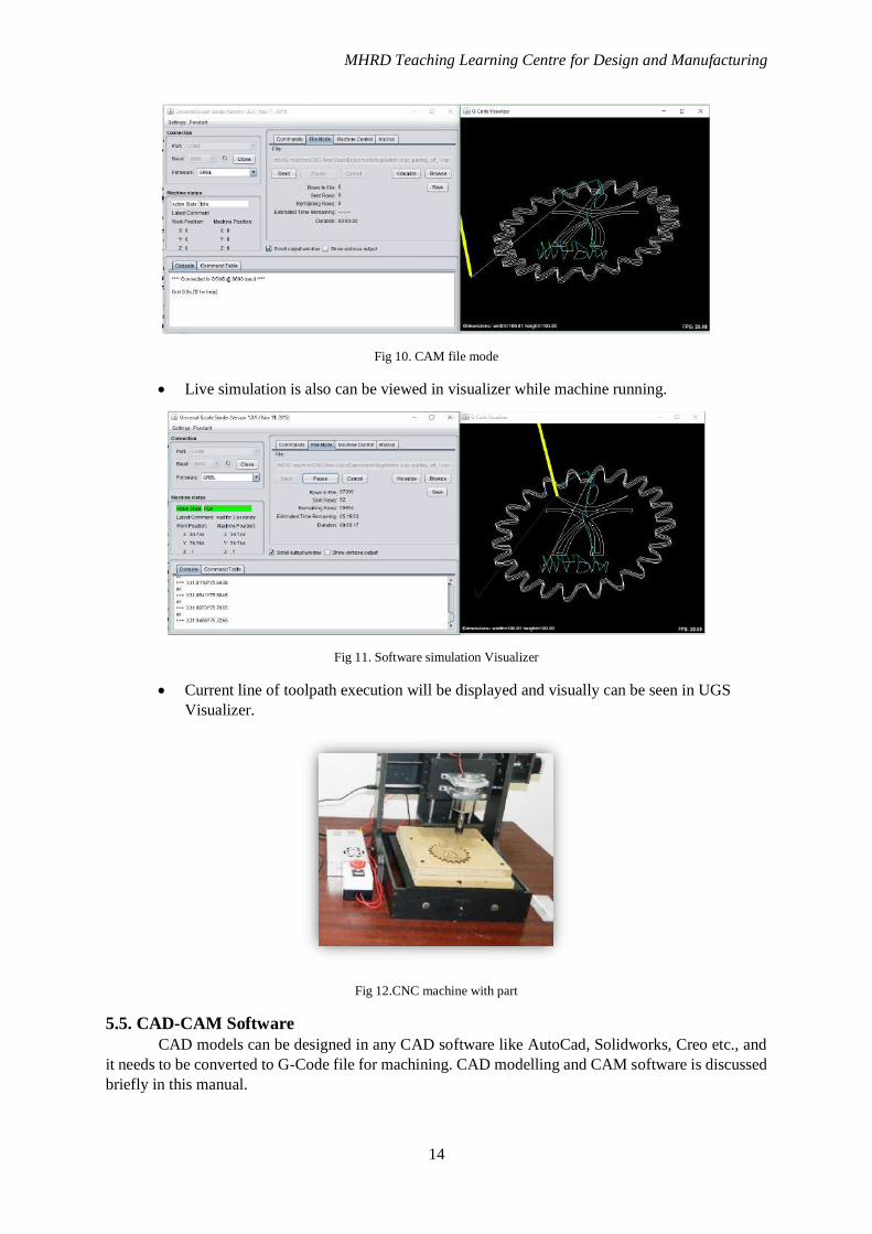
Fig 10. CAM file mode
• Live simulation is also can be viewed in visualizer while machine running.
Fig 11. Software simulation Visualizer
• Current line of toolpath execution will be displayed and visually can be seen in UGS
Visualizer.
Fig 12.CNC machine with part
5.5. CAD-CAM Software
CAD models can be designed in any CAD software like AutoCad, Solidworks, Creo etc., and
it needs to be converted to G-Code file for machining. CAD modelling and CAM software is discussed
briefly in this manual.
MHRD Teaching Learning Centre for Design and Manufacturing
15
5.5.1. CAD Model Designing Software
CAD – Computer Aided Designing is computer software used to create, modify and optimize
3D and 2D designs of product and parts. CAD is basic requirement for any industry or manufacturing
sector. A CAD file explains a product shape, dimension, model type, material, etc. It also can be a
assembly of more than one part. Industrial purpose CAD models are developed mostly in Solid
modelling type whereas other 3D modelling software for animation uses 3D wireframe or surface
modelling.
Few free version CAD modelling software are available for CAD modelling like AutoDesk
123D design, LibreCAD, FreeCAD, SketchUp, AutoDesk Fusion 360 etc. In this manual, a brief
explanation about Fusion 360 Software is given. Fusion 360 is a professional 3D CAD program
software, used for developing 3D modelling, process planning, testing, 3D printing and CAM. Though
it covers whole process of professional software, it is effectively free Software for students and
educators for 3 years.
CAD design of IIITDM institute logo using Fusion 360 is shown in Fig 5
5.5.2. CAM Software
CAM – Computer Aided Manufacturing used alongside of CAD software that generates
machine tool path for CAD model. It generates code for controlling machine tool, and geometric travel
path. The toolpath file can be fed to CNC machine controller for machining the part.
Fig 13. CAD model example in Fusion 360 (a) (b)
MHRD Teaching Learning Centre for Design and Manufacturing
16
Fusion 360 is also supported with free CAM for both addictive (3D printer) and subtractive
manufacturing (Milling Machine). Using this software, machining process plan also can be decided
such as facing, roughing, finishing, drilling etc. Tools for each process can be selected from a standard
tool set or new tools also can be created on custom specifications. Steps for converting CAD model to
G-code toolpath using Fusion 360 is shown below.
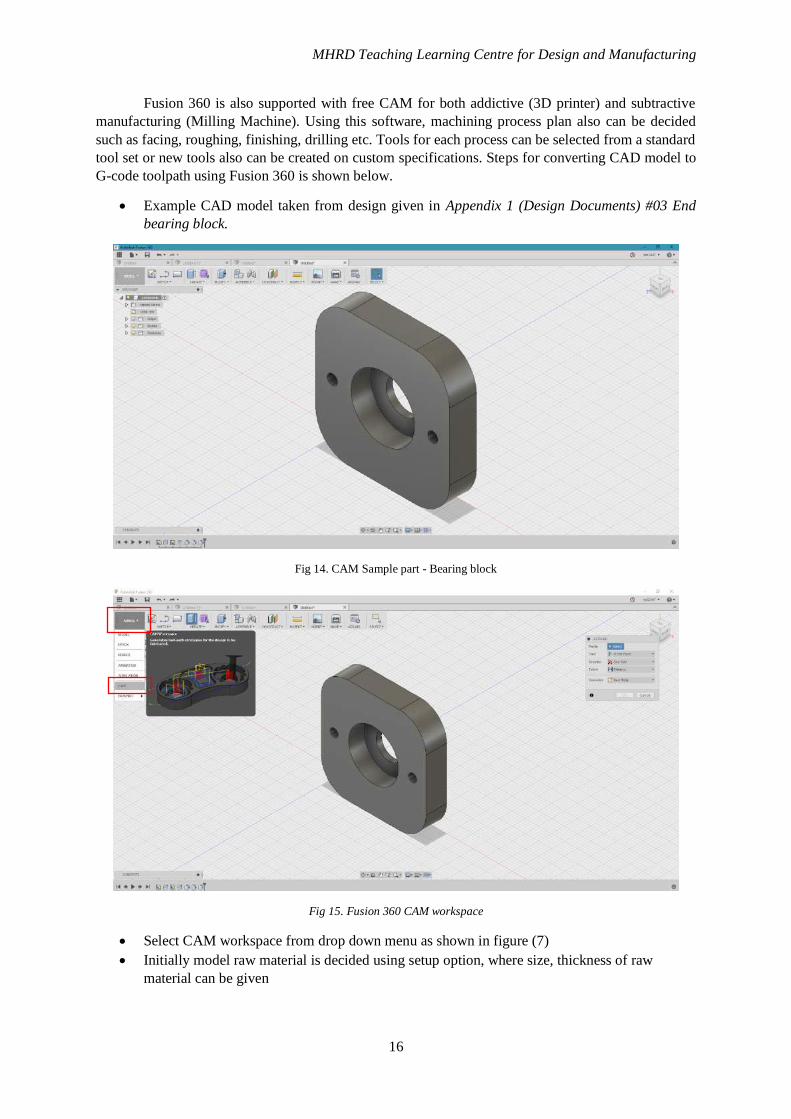
• Example CAD model taken from design given in Appendix 1 (Design Documents) #03 End
bearing block.
Fig 14. CAM Sample part - Bearing block
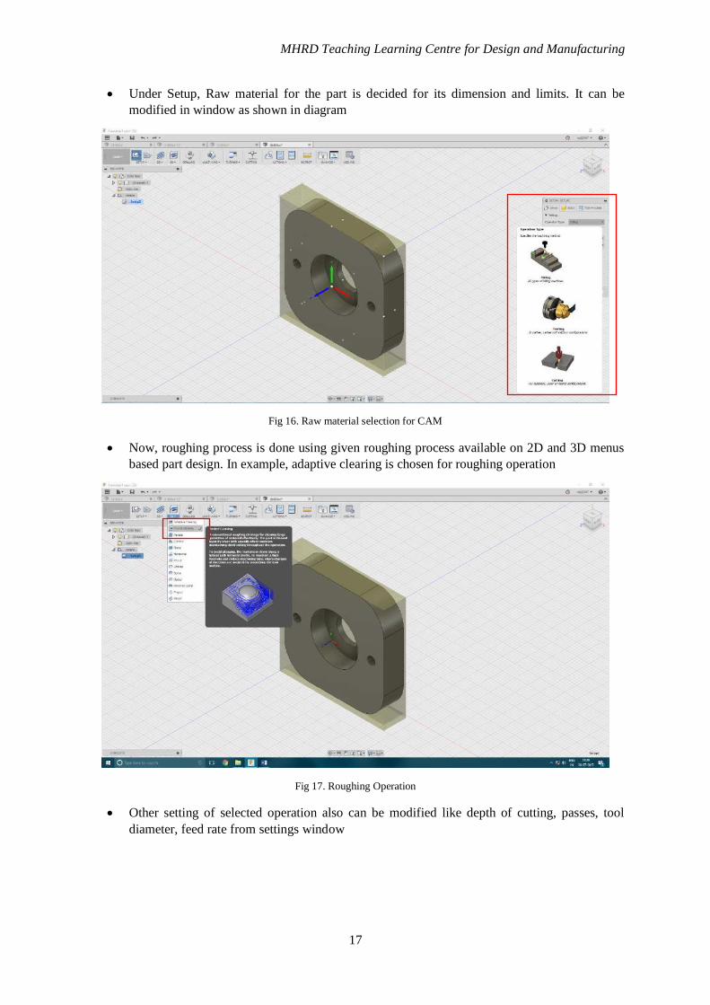
Fig 15. Fusion 360 CAM workspace
• Select CAM workspace from drop down menu as shown in figure (7)
• Initially model raw material is decided using setup option, where size, thickness of raw
material can be given
MHRD Teaching Learning Centre for Design and Manufacturing
17
• Under Setup, Raw material for the part is decided for its dimension and limits. It can be
modified in window as shown in diagram
Fig 16. Raw material selection for CAM
• Now, roughing process is done using given roughing process available on 2D and 3D menus
based part design. In example, adaptive clearing is chosen for roughing operation
Fig 17. Roughing Operation
• Other setting of selected operation also can be modified like depth of cutting, passes, tool
diameter, feed rate from settings window
MHRD Teaching Learning Centre for Design and Manufacturing
18
Fig 18. Tool and CAM settings
• Selecting tool by its type, diameter flute length from standard tool list or custom tool as can be
added.
Fig 19. Toolpath
• Toolpath will be shown once settings are given. Blue line indicated milling path, yellow
indicates travel path without any machining and depth indicates depth pass.
• Similarly based on design’s shape finishing operation also created from 3D menu. After
completing the operation settings, each operation can be simulated as per G-code generated.
• Complete simulation from raw material to finished component can be performed in Fusion
360. Simulation can be selected from project explorer on left side of software
MHRD Teaching Learning Centre for Design and Manufacturing
19
Fig 20. CAM Simulation
• Final Gcode file can be saved from selecting Gcode icon on Actions panel. File can be saved
in various extensions like nc, ngc, gcode which will be accepted by G-code sender software
which we use to control machine.
5.6. Milling machine Samples
Pictures of few sample parts machined with CNC milling machine shown below.
Fig 21. Sample product with Wax – Smiley
MHRD Teaching Learning Centre for Design and Manufacturing
20
Fig 22. Sample product- MDF Board -Alien Face
Fig 23. Sample product MDF - Smiley
MHRD Teaching Learning Centre for Design and Manufacturing
21
APPENDIX I
Design Documents
APPENDIX II
Data Sheets
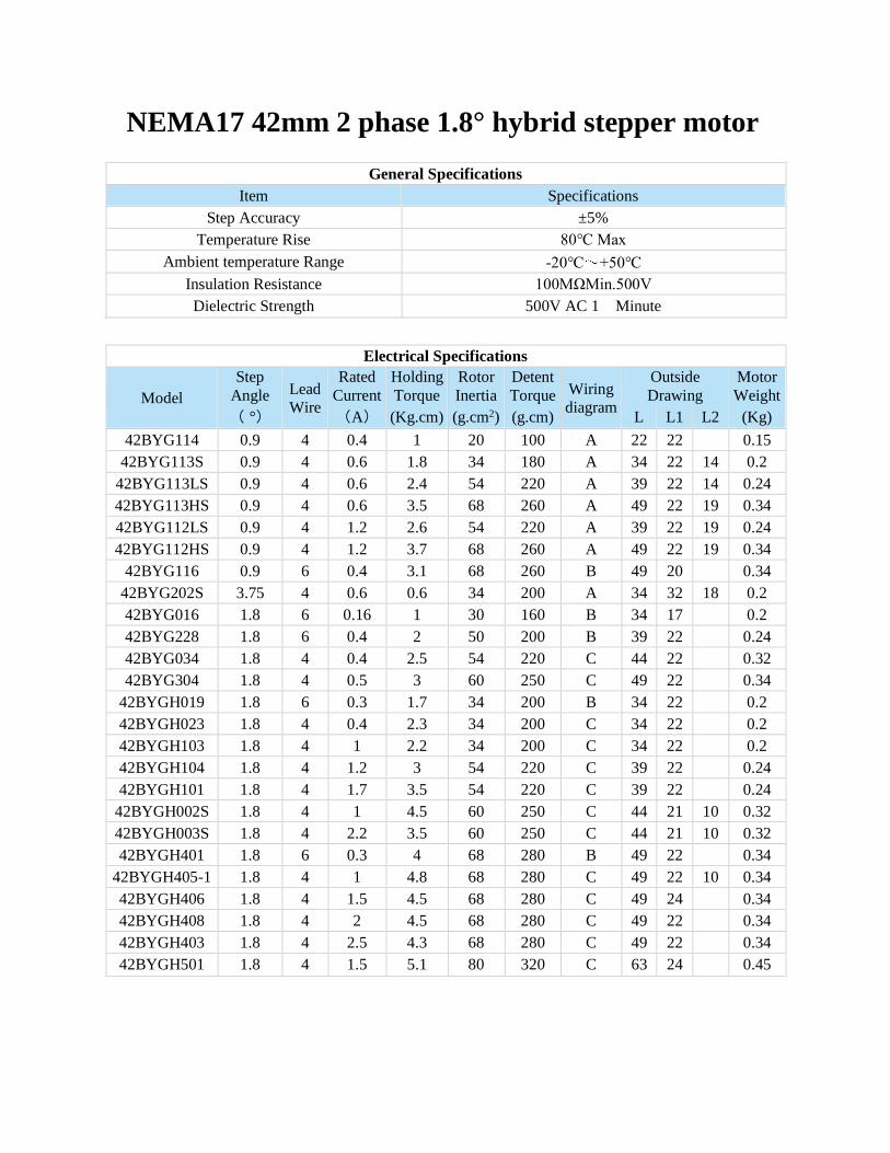
NEMA17 42mm 2 phase 1.8° hybrid stepper motor
General Specifications
Item Specifications
Step Accuracy ±5%
Temperature Rise 80℃ Max
Ambient temperature Range -20℃ +50℃
Insulation Resistance 100MΩMin.500V
Dielectric Strength 500V AC 1 Minute
Electrical Specifications
Model
Step
Angle Lead
Wire
Rated
Current
Holding
Torque
Rotor
Inertia
Detent
Torque Wiring
diagram
Outside
Drawing
Motor
Weight
( °) (A) (Kg.cm) (g.cm2) (g.cm) L L1 L2 (Kg)
42BYG114 0.9 4 0.4 1 20 100 A 22 22 0.15
42BYG113S 0.9 4 0.6 1.8 34 180 A 34 22 14 0.2
42BYG113LS 0.9 4 0.6 2.4 54 220 A 39 22 14 0.24
42BYG113HS 0.9 4 0.6 3.5 68 260 A 49 22 19 0.34
42BYG112LS 0.9 4 1.2 2.6 54 220 A 39 22 19 0.24
42BYG112HS 0.9 4 1.2 3.7 68 260 A 49 22 19 0.34
42BYG116 0.9 6 0.4 3.1 68 260 B 49 20 0.34
42BYG202S 3.75 4 0.6 0.6 34 200 A 34 32 18 0.2
42BYG016 1.8 6 0.16 1 30 160 B 34 17 0.2
42BYG228 1.8 6 0.4 2 50 200 B 39 22 0.24
42BYG034 1.8 4 0.4 2.5 54 220 C 44 22 0.32
42BYG304 1.8 4 0.5 3 60 250 C 49 22 0.34
42BYGH019 1.8 6 0.3 1.7 34 200 B 34 22 0.2
42BYGH023 1.8 4 0.4 2.3 34 200 C 34 22 0.2
42BYGH103 1.8 4 1 2.2 34 200 C 34 22 0.2
42BYGH104 1.8 4 1.2 3 54 220 C 39 22 0.24
42BYGH101 1.8 4 1.7 3.5 54 220 C 39 22 0.24
42BYGH002S 1.8 4 1 4.5 60 250 C 44 21 10 0.32
42BYGH003S 1.8 4 2.2 3.5 60 250 C 44 21 10 0.32
42BYGH401 1.8 6 0.3 4 68 280 B 49 22 0.34
42BYGH405-1 1.8 4 1 4.8 68 280 C 49 22 10 0.34
42BYGH406 1.8 4 1.5 4.5 68 280 C 49 24 0.34
42BYGH408 1.8 4 2 4.5 68 280 C 49 22 0.34
42BYGH403 1.8 4 2.5 4.3 68 280 C 49 22 0.34
42BYGH501 1.8 4 1.5 5.1 80 320 C 63 24 0.45
Mechanical Dimensions:
Wiring Diagram:
APPENDIX III
Bill of Materials
Component SPECIFICATION QTY UNIT PRICE Total priceARDIUNO BOARD (Clone) UNO 1 500 500STEPPER MOTORS NEMA 17 3 600 1800MOTOR DRIVERS M542T MICRO 3 910 2730SMPS 24V,10A 1 1000 1000EMERGENCY SWITCH AC 660V 10A 1 250 250SHAFT BEARINGS SKF- 626 6 260 1560LINEAR BEARINGS LME 12 UU 12 250 3000PVC SHEET 8X600X900 1 870 870LINEAR ROD D=12mm, L=1M 2 550 1100LEAD SCREW ROD WITH FLEXIBLE COUPLINGS M8 , 400mm 3 900 2700SPINDLE MOTOR (Dremel 3000)24-36V DC 1 5500 5500
FASTENERSwood screw 1/2 , 1, 1 1/2 inch 50 no's each 300 300
FASTENERS
M3x20mm,M4x25mm,M5X40mm,M6x20mm with washers and nuts 20 no's each 300 300
TOTAL 21610
BILL OF MATERIAL FOR ONE CNC MILLING MACHINE
REFERENCES
Int. J. Mechanical Engineering and Robotics, vol. 2(1), pp. 6-11.
1
Index Terms— Arduino microcontroller, Build-your-own technology, CNC mill, open source hardware and software.
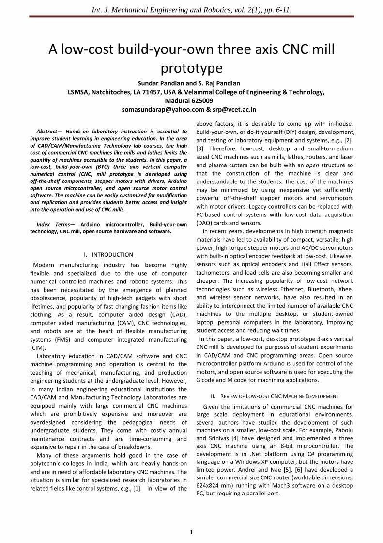
Abstract— Hands-on laboratory instruction is essential to
improve student learning in engineering education. In the area of CAD/CAM/Manufacturing Technology lab courses, the high cost of commercial CNC machines like mills and lathes limits the quantity of machines accessible to the students. In this paper, a low-cost, build-your-own (BYO) three axis vertical computer numerical control (CNC) mill prototype is developed using off-the-shelf components, stepper motors with drivers, Arduino open source microcontroller, and open source motor control software. The machine can be easily customized for modification and replication and provides students better access and insight into the operation and use of CNC mills.
I. INTRODUCTION
Modern manufacturing industry has become highly flexible and specialized due to the use of computer numerical controlled machines and robotic systems. This has been necessitated by the emergence of planned obsolescence, popularity of high-tech gadgets with short lifetimes, and popularity of fast-changing fashion items like clothing. As a result, computer aided design (CAD), computer aided manufacturing (CAM), CNC technologies, and robots are at the heart of flexible manufacturing systems (FMS) and computer integrated manufacturing (CIM). Laboratory education in CAD/CAM software and CNC machine programming and operation is central to the teaching of mechanical, manufacturing, and production engineering students at the undergraduate level. However, in many Indian engineering educational institutions the CAD/CAM and Manufacturing Technology Laboratories are equipped mainly with large commercial CNC machines which are prohibitively expensive and moreover are overdesigned considering the pedagogical needs of undergraduate students. They come with costly annual maintenance contracts and are time-consuming and expensive to repair in the case of breakdowns. Many of these arguments hold good in the case of polytechnic colleges in India, which are heavily hands-on and are in need of affordable laboratory CNC machines. The situation is similar for specialized research laboratories in related fields like control systems, e.g., [1]. In view of the
above factors, it is desirable to come up with in-house, build-your-own, or do-it-yourself (DIY) design, development, and testing of laboratory equipment and systems, e.g., [2], [3]. Therefore, low-cost, desktop and small-to-medium sized CNC machines such as mills, lathes, routers, and laser and plasma cutters can be built with an open structure so that the construction of the machine is clear and understandable to the students. The cost of the machines may be minimized by using inexpensive yet sufficiently powerful off-the-shelf stepper motors and servomotors with motor drivers. Legacy controllers can be replaced with PC-based control systems with low-cost data acquisition (DAQ) cards and sensors. In recent years, developments in high strength magnetic materials have led to availability of compact, versatile, high power, high torque stepper motors and AC/DC servomotors with built-in optical encoder feedback at low-cost. Likewise, sensors such as optical encoders and Hall Effect sensors, tachometers, and load cells are also becoming smaller and cheaper. The increasing popularity of low-cost network technologies such as wireless Ethernet, Bluetooth, Xbee, and wireless sensor networks, have also resulted in an ability to interconnect the limited number of available CNC machines to the multiple desktop, or student-owned laptop, personal computers in the laboratory, improving student access and reducing wait times. In this paper, a low-cost, desktop prototype 3-axis vertical CNC mill is developed for purposes of student experiments in CAD/CAM and CNC programming areas. Open source microcontroller platform Arduino is used for control of the motors, and open source software is used for executing the G code and M code for machining applications.
II. REVIEW OF LOW-COST CNC MACHINE DEVELOPMENT
Given the limitations of commercial CNC machines for large scale deployment in educational environments, several authors have studied the development of such machines on a smaller, low-cost scale. For example, Pabolu and Srinivas [4] have designed and implemented a three axis CNC machine using an 8-bit microcontroller. The development is in .Net platform using C# programming language on a Windows XP computer, but the motors have limited power. Andrei and Nae [5], [6] have developed a simpler commercial size CNC router (worktable dimensions: 624x824 mm) running with Mach3 software on a desktop PC, but requiring a parallel port.
A low-cost build-your-own three axis CNC mill prototype
Sundar Pandian and S. Raj Pandian LSMSA, Natchitoches, LA 71457, USA & Velammal College of Engineering & Technology,
Int. J. Mechanical Engineering and Robotics, vol. 2(1), pp. 6-11.
2
A low-cost, desktop design and evaluation of a CNC machine for modeling and educational purposes is proposed by Pahole, et al. [7]. The working dimensions are 180x140x250 mm. The static rigidity and positional accuracy of the machine are experimentally measured, and the commercial Mach3 machine control software is used with a parallel port-equipped personal computer. Sherring da Rocha, et al. [8] have presented a prototype CNC machine under development running on a PC with LabVIEW which has advantage of ease of visual programming tools. The PC is interfaced with low-cost embedded microcontrollers through the serial port.
The CNC machine designs above rely on the use of stepper motors of limited power in open loop mode. Xu, et al. [9] discuss results of research on an open CNC system using Windows PC with a four-axis motion controller. Wang, et al [10] have developed a CNC system using real-time Ethernet for connection to machine hardware under the Windows NT operating system, with the non-real-time aspect of the operating system accounted for, e.g., by buffering of packets sent. As Windows OS is not guaranteed to provide real-time performance, the use of RTLinux for a software-oriented CNC system with a prototype controller is presented in [11].
A major new development in computer technology is the availability of low-cost open source hardware, such as the Arduino microcontroller platform [12] and the Raspberry PI single board computer [13]. An advantage of open source hardware is that a wide variety of ready-to-use software is available for them on the Web, therefore the prototyping and development times are drastically reduced. Moreover, a wide range of low-cost interfaces, sensors, and accessories such as Arduino shields are also available on the Internet, along with clear instructions, examples, and applicable program code.
Predating the open source hardware, several useful open source software tools have been available in the area of CAD/CAM/CNC software, though these are not so versatile or powerful as the well-established commercial versions. However, for the development of low-cost educational models of CNC machines, such tools may be quite adequate from the viewpoint of machine control. Therefore, in this paper, the development of a prototype 3-axis desktop CNC mill using Arduino-based control system is presented.
III. PROTOTYPE 3-AXIS CNC MACHINE
A. Mechanical System To speed up the development of the CNC prototype
system, a ready-to-assemble CNC carving machine kit from Zen Toolworks, USA has been used in this work [14]. The kit is supplied with three stepper motors for the three axes, the frame parts, the lead screws, guide rods, anti-backlash falans and springs, and related accessories. The body of the machine is made of high density PVC boards. It has a fixed gantry and a mobile bed, and therefore a limited working range which however compares well with the specifications of the commercial CNC mill currently under use in our
laboratory. The main specifications of the assembled CNC machine
are listed below:
Table 1. CNC machine characteristics X axis travel 178 mm (7") Y axis travel 178 mm (7") Z axis travel 50 mm (2") Stepper motors 3xNema 17, 1.8o, 200
step/rev, 2-phase, 4 wire, bipolar, 1.3A
Lead screws Stainless steel, 3xM8x1.25, 20 tpi
Spindle motor 24-36 V DC, 5000-8000 rpm, 0.3A no load
Power supply 24 V, 15A, 360 W, switching power supply
Stepper motor drivers
3xsingle axis, rated 3A, peak 3.5A, 24V DC rated, up to 1/16 microstepping, adjustable step, current, and half-decay
Microcontroller Arduino Uno, R3 board, with ATmega328P @ 16MHz
A photograph of the assembled CNC machine is shown in
Fig. 1. The rotary tool shown is temporarily used for milling and carving, and is to be replaced by the spindle motor specified above.
Fig.1. Assembled 3-axis CNC machine
B. Electronic Control System Fig. 2 below shows the connections to the Arduino
microcontroller and stepper motor drivers for controlling the CNC machine. For space saving convenience, the electronics assembly is mounted on the rear of the gantry.
The single-axis TB6560 stepper motor driver from SainSmart [15] is used each axis of motion, so that in the case of motor drive problems the single boards can be swapped out, without the trouble of replacing an entire multi-axis driver board. Of late, dedicated Arduino shield stepper driver boards to interpret the machine motion commands sent by the microcontroller are also available on the market.
Int. J. Mechanical Engineering and Robotics, vol. 2(1), pp. 6-11.
3
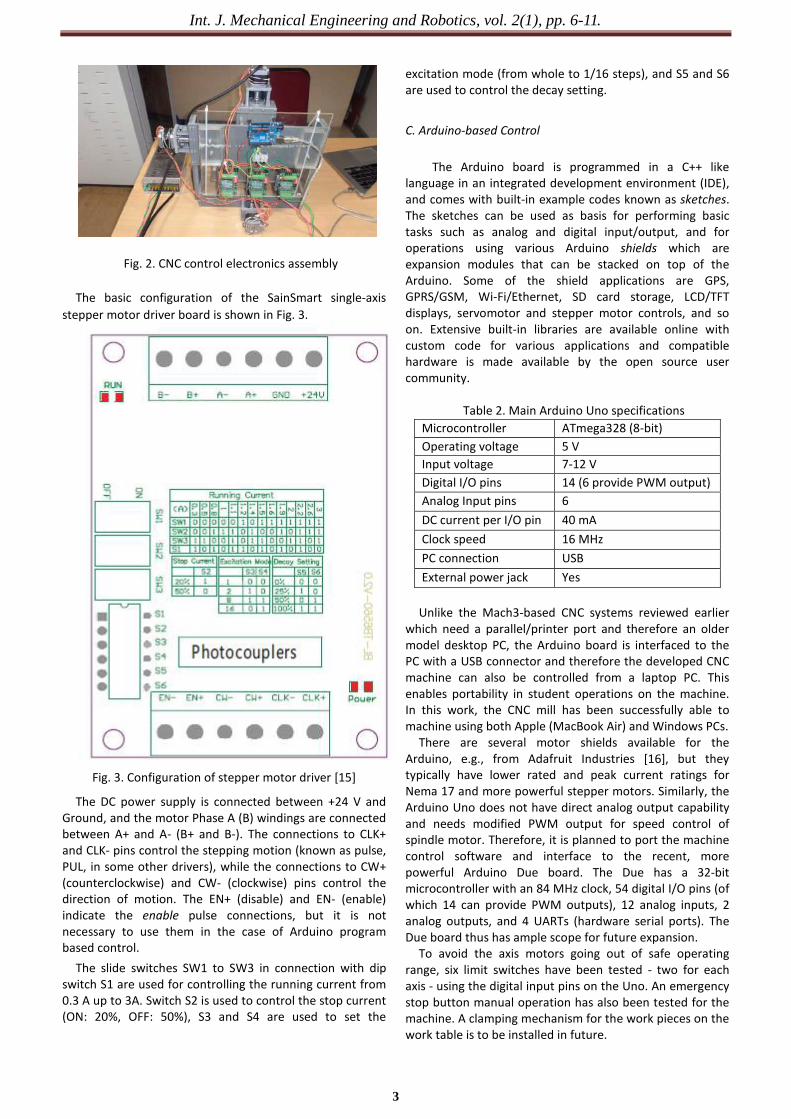
Fig. 2. CNC control electronics assembly The basic configuration of the SainSmart single-axis
stepper motor driver board is shown in Fig. 3.
Fig. 3. Configuration of stepper motor driver [15]
The DC power supply is connected between +24 V and Ground, and the motor Phase A (B) windings are connected between A+ and A- (B+ and B-). The connections to CLK+ and CLK- pins control the stepping motion (known as pulse, PUL, in some other drivers), while the connections to CW+ (counterclockwise) and CW- (clockwise) pins control the direction of motion. The EN+ (disable) and EN- (enable) indicate the enable pulse connections, but it is not necessary to use them in the case of Arduino program based control. The slide switches SW1 to SW3 in connection with dip switch S1 are used for controlling the running current from 0.3 A up to 3A. Switch S2 is used to control the stop current (ON: 20%, OFF: 50%), S3 and S4 are used to set the
excitation mode (from whole to 1/16 steps), and S5 and S6 are used to control the decay setting.
C. Arduino-based Control
The Arduino board is programmed in a C++ like language in an integrated development environment (IDE), and comes with built-in example codes known as sketches. The sketches can be used as basis for performing basic tasks such as analog and digital input/output, and for operations using various Arduino shields which are expansion modules that can be stacked on top of the Arduino. Some of the shield applications are GPS, GPRS/GSM, Wi-Fi/Ethernet, SD card storage, LCD/TFT displays, servomotor and stepper motor controls, and so on. Extensive built-in libraries are available online with custom code for various applications and compatible hardware is made available by the open source user community.
Table 2. Main Arduino Uno specifications Microcontroller ATmega328 (8-bit) Operating voltage 5 V Input voltage 7-12 V Digital I/O pins 14 (6 provide PWM output) Analog Input pins 6 DC current per I/O pin 40 mA Clock speed 16 MHz PC connection USB External power jack Yes
Unlike the Mach3-based CNC systems reviewed earlier which need a parallel/printer port and therefore an older model desktop PC, the Arduino board is interfaced to the PC with a USB connector and therefore the developed CNC machine can also be controlled from a laptop PC. This enables portability in student operations on the machine. In this work, the CNC mill has been successfully able to machine using both Apple (MacBook Air) and Windows PCs. There are several motor shields available for the Arduino, e.g., from Adafruit Industries [16], but they typically have lower rated and peak current ratings for Nema 17 and more powerful stepper motors. Similarly, the Arduino Uno does not have direct analog output capability and needs modified PWM output for speed control of spindle motor. Therefore, it is planned to port the machine control software and interface to the recent, more powerful Arduino Due board. The Due has a 32-bit microcontroller with an 84 MHz clock, 54 digital I/O pins (of which 14 can provide PWM outputs), 12 analog inputs, 2 analog outputs, and 4 UARTs (hardware serial ports). The Due board thus has ample scope for future expansion. To avoid the axis motors going out of safe operating range, six limit switches have been tested - two for each axis - using the digital input pins on the Uno. An emergency stop button manual operation has also been tested for the machine. A clamping mechanism for the work pieces on the work table is to be installed in future.
Int. J. Mechanical Engineering and Robotics, vol. 2(1), pp. 6-11.
4
IV. CNC MACHINE CONTROL SOFTWARE
The basic process of CNC-based manufacturing is illustrated in Fig. 4. The part or good to be machined is designed in a computer-aided design (CAD) software, whose output is a drawing in one of many acceptable formats. This drawing is then fed to the computer-aided manufacturing (CAM) software, whose output is the machine readable code used for numerical control of the machine.
Fig. 4. Process of CNC machining
The machine readable code contains alphanumeric
instructions to the machine in the form of G and M code [17]. Typically, it is expressed as N (followed by a three or more digit sequence number), G (followed by two digits, for preparatory functions such as motion commands), followed by X (position along X axis to move to), Y, Z. Other functions include F (for feedrate, or speed of the cutting tool in the cutting direction), M (for miscellaneous commands or functions, e.g., coolant on/off, tool change, etc.), T (tool function), and S (spindle speed function).
Since implementation of the G code is machine dependent, it is necessary to test out different choices for an open source G code interpreter for the Arduino, so that the correct motions are obtained for the machine axes through the stepper motor driver. We have used grbl, an open source G-code interpreter or milling controller for the Arduino developed by Simen Skogsrud [18], [19]. It implements in optimized C a subset of the RS-274/NGC (next generation controller) standard and has been tested to work with the G-code of several commercial CAM tools. It has up to 30 kHz step rate, and achieves precise timing and asynchronous operation. Accuracies of up to 0.1 mm have been reported by users of the software.
Compiled Arduino sketch or program files are in the form of .hex files. An open source Arduino hex uploader program called XLoader (available for download at http:// russemotto.com/xloader/) is used to upload the grbl hex file directly to the Arduino, without the need for a flash programmer. It is available for Windows only, but for Apple or other operating system, the uploading to Arduino can be done first using a Windows computer.
The interface of XLoader appears as in Fig. 5. The user needs to select the appropriate dropdown menus for Arduino Uno, the grbl hex file being loaded, and the correct COM port of the computer to which the Uno is connected, with the baud rate for the Uno being set at 9600.
The next and final step is to use a program to send the G-code for the specific machining job to the microcontroller loaded with grbl. For this purpose, we use another open source program called Universal-G-Code-Sender, which is a Java-based grbl compatible cross platform program [20].
Fig. 5. Use of XLoader program for uploading grbl
controller hex file to Arduino A screenshot of the Universal G Code Sender program in
use is shown in Fig. 6.
Fig. 6. Screenshot of Universal G Code Sender program
In this case, we set the correct serial port and baud rate,
set line terminator to \r\n, and in the File Mode, select the G-code text file for the machining operation being undertaken. The program is quite versatile, in that it also has a Command Mode in which users can interactively enter G code commands, and a Manual Control Mode in which users can manually increment and decrement motions along the individual axes. The program provides options to reset the current coordinates to zero, or to return the machine to zero positions, as well as perform a homing operation.
An alternative to Universal G Code Sender that works directly with grbl shield for Arduino, is the GRBL Controller [21]. It also has the option to display in real time the current machine position coordinates and the current work position coordinates.
The authors have tested the prototype 3-axis CNC machine with various G code files for carving different shapes in acrylic and wood workpieces, e.g., square with curved edges, circle, and images. Satisfactory results have been obtained in all cases. For learning purposes, the Command Mode of the G Code Sender program prints out a list of options and settings, using which the specifications for the operation can be used and stored on the Arduino, e.g., steps per mm of each axis. Moreover, students can be encouraged to extensively try out the combinations of settings for the motor driver. The CNC kit maker also provides recommended feedrates and cutting depths for different materials.
Int. J. Mechanical Engineering and Robotics, vol. 2(1), pp. 6-11.
5
V. SCOPE FOR FUTURE WORK
It is planned to scale up the prototype CNC machine in terms of size, use more powerful motors, strengthen the frame and worktable with materials like aluminum or cast iron, and augment the CNC control software with software for simulation ahead of actual run.
For instructional purposes as well as for more precise operation, it is preferable to build CNC machines with DC or AC servomotors and encoder feedback using PC-based motion controllers [22]. The students can be encouraged to explore improvements to the system using alternative open source hardware like the Raspberry Pi, as well as shields. The open structure of the CNC machine will enable the students to gain a better understanding of the design and operation of the mechanical subsystem. Further, as students gain a solid understanding of the open source Arduino microcontroller platform and associated open source machining software, they can be encouraged to build their own prototypes at even lower cost, e.g., using cheaper lower-power stepper motors or recycled motors from old printers, construct the machine frame and work table with cheaper materials like plywood, and innovatively create actuation mechanisms from available stock like threaded rods, e.g., [23].
Machines in general, and robots in particular, are appealing to youth and children. Therefore, exposure to and experience with DIY robots and mechatronic system projects can render engineering education innovative through playful learning [24].
In some industrialized countries, school children are exposed to CNC programming and machining as early as middle school [25]. Therefore, with the power of the Internet, it is also planned to introduce neighborhood school children remotely to Web-based real-time operation of CNC machines, while imparting them basic knowledge of computer-aided art, design, and modeling through open source software such as Google SketchUp [26].
VI. CONCLUSIONS
This paper has presented the results of development of a low-cost three-axis vertical CNC mill suitable for adoption in undergraduate mechanical engineering laboratory setting. The total cost of the developed system is just about 1/20th of the existing commercial CNC machine used currently in the laboratory, though pedagogically our model provides more scope for hands-on learning by the students and therefore better learning outcomes. It is hoped to extend this work in future to low-cost design and development of other CNC machines like lathe, router, and eventually a BYO or customized open source 3D printer.
REFERENCES
[1] D.S. Bernstein, "Setting up and running a control research laboratory", IEEE Control Systems Magazine, vol. 23, pp. 14-19, 2003.
[2] K. Nagai, "Learning while doing: Practical robotics education", IEEE Robotics & Automation Magazine, vol. 8, pp. 38-43, June 2001.
[3] N. Raju, N. Beedu, N. Lakshminarasamma, and V. Ramanarayanan, "A do-it-yourself (DIY) switched mode power conversion laboratory", Proc. India Int. Conf. Power Electronics, Chennai, pp. 289-292, 2006.
[4] V.K. Pabolu and K.N.H. Srinivas, "Design and implementation of a three dimensional CNC machine", Int. J. Computer Science and Engineering, vol. 2, pp. 2567-2570, 2010.
[5] T. Andrei and I. Nae, "Practical applications performed by a stepper motor CNC router", Seria Techica, vol. LXII, pp. 127-138, 2010.
[6] I. Nae and T. Andrei, "Designing and building a CNC router using stepper motors", Seria Technica, vo. LXII, pp. 55-62, 2010.
[7] I. Pahole, L. Rataj, M. Ficko, S. Klancnik, S. Brezovnik, M. Brezocnik, and J. Balic, "Construction and evaluation of low-cost table CNC milling machine", Scientific Bulletin, Series C: Mehcanics, Tribology, Machine Manufacturing Technology, vol. XXIII, pp. 1-7, 2009.
[8] P.A. Sherring da Rocha Jr., R.D.S. Souza, and M. Emilia de Lima Tostes, "Prototype CNC machine design", J. of Energy and Power Engineering, vol. 6, pp. 1884-1890, 2012.
[9] X. Xu, Y. Li, J. Sun, and S. Wang, "Research and development of open CNC system based on PC and motion controller", Procedia Engineering, vol. 29, 1845-1850, 2012.
[10] K. Wang, C. Zhang, X. Xu, S. Ji, and L. Yang, "A CNC system based on real-time Ethernet and Windows NT", Int. J. Adv. Manuf. Technol., vol. 65, pp. 1383-1395, 2013.
[11] H. Ji, Y. Li, and J. Wang, "A software oriented CNC system based on Linux/RTLinux," Int. J. Adv. Manuf. Technol., vol. 39, pp.291-301, 2008.
[26] S.R. Pandian, K. Hashimoto, K. Dery, and R. Victor, 2004, “Internet-based Control of a Prototype Underwater Robot”, Proc. Underwater Intervention 2004, New Orleans, LA, USA.