22
A Case Study in Applying RDM® to Automotive BIW Design Oliver Tomlin October 2013

A Case Study in Applying RDM® to Automotive BIW Design
Oliver Tomlin
October 2013

Contents
• The Reinforcement Derivation Method (RDM®)
• The Automotive Body Design problem
• Interpretation and Example results
• Other Applications?

What is RDM®? • It combines the Topology method with an incredibly
efficient way of creating links to an existing structure.
• It is Genesis’ ability to deal with very small volume fractions that allows this method to succeed.
• It came from Martin’s head as a light bulb moment! Once we had calmed him down and got him to speak coherently again all became clear!
• In the first few weeks it was called “Magic Custard” with reference to the fact that all results seemed to be yellow!

The Reinforcement Derivation Method (RDM®)
• RDM® defines the additional reinforcements and load-paths to support a pre-existing structure in the relevant locations to achieve specified targets.
• A significant advantage is the use with a pre-existing structure and load-cases and the simplicity of creating it.
Top-hat Beam with RDM placed to maximise stiffness for a UDL.

RDM®’s Application in BIW Design
• Classical BIW Topology Optimisation can be hard to interpret.
• It also creates structures that are not specific to a manufacturing process, when an Automotive BIW is generally defined by its annual volumes.
• Can only ever be applied before a platform/chassis is defined.
BIW Topology Optimisation Result

Why No Blank Sheet?
• Every structural engineer would like to believe that the layout of the BIW is entirely driven by the efficiencies of load management.
• But having packaged the occupants, the powertrain, some doors and styled the vehicle there is little space for the structure to sit!
• Generally the body structure fills the gaps left by the more important items that make a vehicle function.

Importance of First Mode
• Assessment of fully free natural frequency of the untrimmed BIW:
– This analysis can precede release of all trim, closures and finer details
– Ensures efficient usage of mass (a low frequency is either heavy or soft).
– A good high frequency produces a vehicle that is • Quieter
• Feels of higher quality
• Has better handling
• Retain these characteristics for its lifetime.
– Combined with a static torsion test the BIW can be
developed with “honesty” in each update.
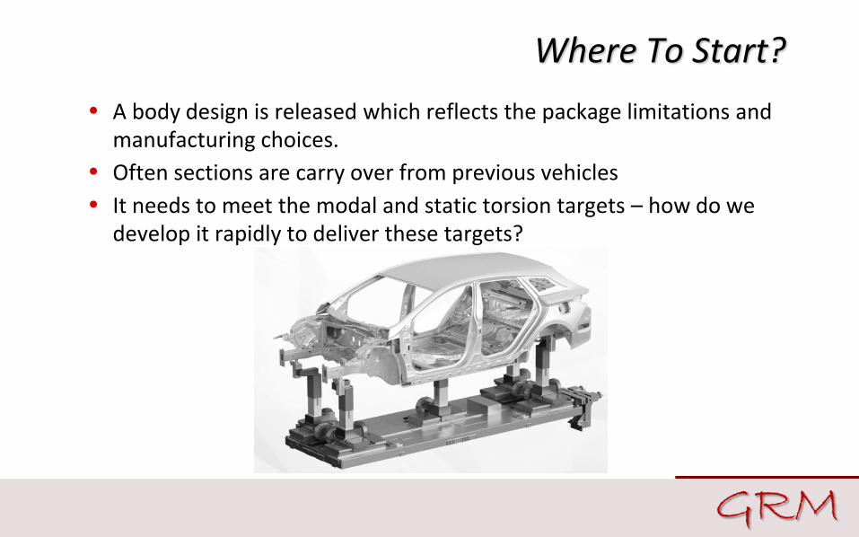
Where To Start?
• A body design is released which reflects the package limitations and manufacturing choices.
• Often sections are carry over from previous vehicles
• It needs to meet the modal and static torsion targets – how do we develop it rapidly to deliver these targets?

The Example Fiesta FE Model
• 2002 Ford Fiesta used for our study, previously validated to a number of tests.
• Mass 405kg (inc bolt on parts)
2002 Ford Fiesta courtesy BAARG
Item
First Mode (Hz)
Static Torsion (kNm/deg)
Test Vehicle (5dr)
32.8 10.6
FE Model (3dr)
27.8 11.8

RDM®
• An FE mesh of the vehicle is our starting point.
• The RDM® region is automatically created in Design Studio over the top at user-defined limits.
• Genesis carries out an optimisation for multiple load-cases, removing superfluous material and only leaving the most important parts.

Interpreting the Results
• Joining (Spot-welds) – No additional mass
– Minimal cost increase
• The RDM® result is ideal for identifying areas of weakness and demonstrates the most effective solution.
• However, the results need to be interpreted into feasible changes which will satisfy manufacturing and practicality constraints. 3 options apply:
• Geometry Modifications – Minimal mass addition
– No extra tools or processing
• Additional Components – Largest stiffness
improvements

Joining (Spot-welds)
• The smaller local RDM® “nuggets” are represented as spot-welds. A total of 10 were created which increased the body stiffness by 1% for no mass change.

Geometry Updates
• Extension of Body Side inner and reinforcement to improve connection with rear boot aperture.
– 1.7kg (0.4%) mass increase
– 1.2Hz (5%) increase in first mode.
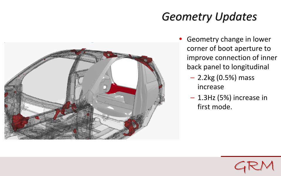
Geometry Updates
• Geometry change in lower corner of boot aperture to improve connection of inner back panel to longitudinal
– 2.2kg (0.5%) mass increase
– 1.3Hz (5%) increase in first mode.

Geometry Updates
• Shape change of back panel around latch cutout and edge of spare wheel clearance.
– 1.2kg (0.3%) mass increase
– 1.9Hz (7%) increase in first mode.

Geometry Updates
• Geometry change in upper corner of boot aperture to reduce offset in flow of load-paths.
– 0.06kg (0.01%) mass increase
– 3.7Hz (13%) increase in first mode.

Additional Component
• Additional connection between rear suspension turret top and back panel.
– 1.2kg (0.3%) mass increase
– 6.5Hz (23%) increase in first mode.
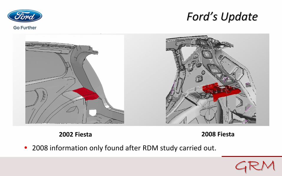
Ford’s Update
2002 Fiesta 2008 Fiesta
• 2008 information only found after RDM study carried out.

RDM® Performance Improvements • 10 spot welds, 4 geometry changes and 1 extra panel.
– First Mode increased from 28Hz to 40Hz (43%)
– Static Torsion increased from 11.8kNm/deg to 19.8kNm/deg (68%)
– At a cost of 7.5kg (1.8%)
– These are quite clearly efficient performance improvements as the static stiffness has increased more than modal performance.
• Quite literally all in a day (or two’s) work!
• Final question – can we reduce the mass penalty and maintain the
same performance?

Thic
knes
s C
han
ge (
mm
)
Gauge Optimisation
Increase Only
Increase & Decrease
No Thickness Change
BIW
First Torsion Mode (Hz) Mass (kg) Torsional Stiffness (kNm/deg)
Baseline 27.8 405 11.8
Modifications from RDM 39.9 412 19.8
Gauge Optimised 40.0 383 19.8

Overview
• The Reinforcement Derivation Method (RDM®)
• Interpretation and Example results
• Other Applications?
• The Automotive Body Design problem

What Else Can RDM Be Used For?
• Plastic trim parts
• Gearbox casings
• Bulkhead designs
• Stiffness for mounting energy absorbing components.
• Non-automotive applications
• Definition of design spaces around existing designs for classical topology.
• Any Questions?


