Page 1
A Case Study on a Fire-Induced Collapse Accident of aReinforced Concrete Frame-Supported Masonry Structure
Author
Li, Yi, Lu, Xinzheng, Guan, Hong, Ying, Mingjian, Yan, Weiming
Published
2016
Journal Title
Fire Technology
Version
Accepted Manuscript (AM)
DOI
https://doi.org/10.1007/s10694-015-0491-0
Copyright Statement
© Springer Science+Business Media New York 2015. This is an electronic version of an articlepublished in Fire Technology, Volume 52, Issue 3, pp 707–729, 2016. Fire Technology isavailable online at: http://link.springer.com/ with the open URL of your article.
Downloaded from
http://hdl.handle.net/10072/125063
Griffith Research Online
https://research-repository.griffith.edu.au
Page 2
1
A case study on a fire-induced collapse accident of a
reinforced concrete frame-supported masonry structure Yi Li a, Xinzheng Lu b*, Hong Guan c, Mingjian Ying b, Weiming Yan a
a. Key Laboratory of Urban Security and Disaster Engineering of Ministry of Education, Beijing Collaborative Innovation Center for Metropolitan Transportation, Beijing University of
Technology, Beijing 100124, China b. Key Laboratory of Civil Engineering Safety and Durability of Ministry of Education,
Department of Civil Engineering, Tsinghua University, Beijing 100084, China c. Griffith School of Engineering, Griffith University Gold Coast Campus, Queensland 4222,
Australia *Corresponding Author: Xinzheng Lu, Email: [email protected] Tel:+(86)10 62795364,
Fax:+(86)10 62795364
Abstract: In 2003, an 8-storey reinforced concrete (RC) frame-supported masonry
structure, located in Hengyang City, China, underwent a severe fire-induced collapse
accident. Information on the structure and the fire scenario is presented. It includes the
design data, the site observation record of the fire incident, and the laboratory material
test results. Preliminary investigation reveals that about 45.9% of the bottom storey of
the RC frame was predicted to have experienced temperatures in excess of 800ºC, and
its central area was predicted to have reached almost 1300ºC. Such a severe fire load,
of fairly high temperature and covering a large area, is thought to be the primary
cause of the progressive collapse of the entire building structure. To better understand
the collapse mechanism, this study presents a coupled thermo-mechanical numerical
simulation of the building collapse. The simulation results confirm that the actual
collapse area is well reproduced by the proposed numerical model. The simulation
further demonstrates that the initial damage happened to two interior columns exposed
to an extreme temperature of 1300ºC. Such damage was also attributable to the large
gravity load they carried, and the complicated nature of the local structural
arrangements. Their adjacent structural members were subsequently damaged,
because they were also weakened by the severe fire, and they were over-loaded by the
redistributed load originally resisted by the two formerly damaged columns. Failure of
the two interior columns and their adjacent area eventually triggered a progressive
collapse of the remaining structure. Further, the effect of some critical factors on the
Page 3
2
collapse mechanism is discussed. On the basis of this numerical case study, practical
design considerations on the key structural components, the fire compartments, and
the structural robustness are given for the prevention of the fire-induced progressive
collapse of RC frame structures.
Keywords: Frame-supported masonry structure; fire-induced collapse; site
investigation; numerical simulation
1 Introduction
In 2003, the Hengzhou Building, an 8-storey RC frame-supported masonry structure,
located in the Hengyang City of China, suffered a severe fire. Following an
approximately three hour fire, the building collapsed. It claimed the lives of 20
firefighters, with 16 injuries. A fire-induced collapse is a complicated mechanical
behavior of an overall structural system under a critical limit state. Such a behavior
covers material degradations (at high temperature), large deformations of structural
members, and load redistributions in structural systems. An in-depth investigation into
the real-world mechanism of a fire-induced collapse incident of a building structure or
structures would be very helpful for understanding their overall mechanical behavior
in fire. However, such a scientific investigation is rarely reported. Thus, this study
aims to present a case study on the Hengzhou Building, which will provide useful
engineering lessons for improving fire-induced collapse prevention design
considerations.
Existing studies have demonstrated that the behavior of structural elements under fire
can be different from that observed during the standard furnace tests [1]. In a real
scenario, when a building is exposed to a fire, additional internal forces are produced
because the fire-induced thermal expansions of the structural components are
restrained by the surrounding components. However, this important effect is often
neglected in the standard furnace tests on structural components, where constant loads
Page 4
3
are normally applied [2]. During the late 1990s, a series of full-scale fire tests were
successfully conducted at the Large Building Test Facility of the Building Research
Establishment (BRE) at Cardington. These tests studied the fire resistance of entire
steel and concrete structures [3-5]. Despite such research efforts, similar large-scale
tests were not widely used in the fire safety design and the analysis of the entire
structural systems due to extremely high laboratory and labor costs. In contrast,
Mostafaei [6] adopted a hybrid experimental method to study the fire resistance of a
single column in a structural system. Similar work was conducted at the CERIB of
France, which has testing facilities with active loading systems [7]. However, the
capacity of the fire furnaces limited the size and number of the structural members to
be tested[8].
A numerical simulation, on the other hand, offers a low-cost and effective tool to
evaluate the fire performance of an overall structure system. Many researchers have
developed numerical models to simulate the behavior of steel and concrete
structures under fire, such as SAFIR [9] and VULCAN [10]. In addition, commercial
finite element (FE) codes, such as ABAQUS, have been adopted by others [11-13] to
perform the analysis of structures at elevated temperatures. Furthermore, research
efforts to promote more feasible and more robust numerical methods are still in high
demand and these methods must be carefully validated with representative
experimental results.
In addition to the experimental and analytical methods, accident investigation is also
an important methodology for studying the fire resistance of an overall structural
system. Unlike the idealized structural models used in experimental and analytical
studies, real-world structures are free from any simplifications. The critical issues that
may be neglected in existing engineering designs and analyses can be discovered
through accident investigations of real structures under fire accidents.
For example, in studying the collapse of the World Trade Center (WTC) towers in
Page 5
4
New York, Usmani et al. [14] discovered that the building floors were softened by fire
and, in turn, the lateral restraint of the peripheral truss columns were weakened. These
outcomes resulted in a large, horizontal tensile force from the floor on the peripheral
truss columns, and eventually accelerated the failure of the columns. These aspects
were, however, not considered in the original design of the WTC. Quintiere et al. [15]
suggested that the insulation thickness on the truss rods was insufficient, thereby
causing the over-heating of the steel. In turn this led to the weakening and collapsing
of the trusses. NIST [16-19] also conducted a comprehensive investigation of this
accident and provided many important conclusions which promoted on-going efforts
in fire safety research.
Other studies have address buildings under severe fire, for example, the Windsor
Tower of Madrid. The fire development of this accident was studied to replicate the
growth and spread of the fire and identify the impact of the fire on structural
behavior[20]. The lack of fire protection for the steelwork was believed to be the major
reason for the partial collapse of the building[21]. In addition, similar work was also
been conducted to provide engineering lessons from fire-induced collapse accidents of
some other real structures and commercial building projects [22].
To implement the direct assessment of the performance of the overall structural
systems under fire, comprehensive fire incident reports and investigations (including
details such as the design data, the structural damage, and the fire development
scenario) can provide very valuable and representative benchmark models for fire
science. These models can also be used to conduct in-depth studies of the structures
under fire through which new methodologies for fire analysis can be validated, and
potential fire-induced problems of typical structures can be further explored. However,
detailed fire incident reports on other fire-induced collapse accidents[23], other than
those for the WTC and the Windsor Tower fires, are still very limited in the literature.
In the current study, the complete structural and fire data of the Hengzhou Building,
Page 6
5
including its design information, the site observation records for the fire disaster, and
the laboratory material test results, were collected and summarized to provide a
benchmark case for further fire studies. To gain an in-depth understanding of the
collapse mechanisms, the entire collapse process of the structure was simulated using
a combination of fiber beam elements, multi-layer shell elements, component failure
criteria, and elemental deactivation technology. The primary cause of the fire-induced
structural collapse is discussed, and suggestions are given to the progressive collapse
prevention design considerations against fire hazards.
2 Structural and material related data of the building
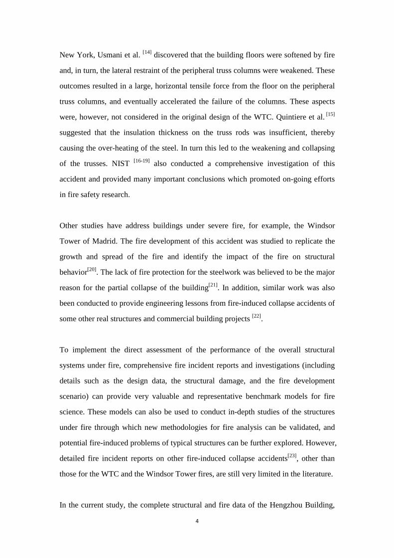
Located in Hengyang, China, the 1998 constructed Hengzhou Building was an
8-storey, 25.8-m tall RC frame-supported masonry structure. The planar layout of the
building is shown in Figure 1. Its ground floor was 4.8 m high and it was originally
designed for commercial use. The first through to the seventh floors of the building
were 3 m in height, and these stories were designed for the residents. The design loads
consisted of 5kN/m2 of dead load and 2kN/m2 of live load.
1 2 4 6 8
1 2 3 5 7 9
F
E
D
C
B
A
403005700 7200 5600 7300 4900 5400 4200
403005700 6000 3900 6200 6200 8100 4200
3100
066
0066
0066
0063
0049
00 600×600
10 11 12
11 12
B1
B2
B2
B1
B1
B1
B3
B3
B2(450×1350)
B4(400×1300)
B4(450×1000)
B5(450×1250)
B3
B3
B3
B3
Labels of columns: C2, C3C1,
Sectional size of beams in east-west direction: 400×1300
B2(450×1350)
B3(450×1350)
600×600
600×600
600×600
600×600600×600
600×500
600×500
600×500
600×500
600×500600×500
600×500
600×500600×600
Sectional size of unspecified columns: 500×500
N
Labels of beams: B1, B2, B3, B4, B5
Figure 1 Structural arrangement of the ground floor frame and member sizes (unit: mm)
Page 7
6
2.1 RC frame on the ground floor
The structural layout of the ground floor frame, as well as the dimensions and
designations of the structural components, is detailed in Figure 1. The reinforcement
details of the frame are given in Table 1. The floor slabs were precast and were
separated from the main frame. The concrete strength was C30 for the columns and
beams, with a design compressive strength, fc, of 20.1 MPa. Through the on-site
rebound hammer test and the laboratory compressive test of the drilled cores [24,25], the
actual compressive strength of the concrete samples that were free from fire damage
varied from 28.0 MPa to 41.7 MPa, with an average strength of 36.2 MPa, and a
standard deviation of 4.1 MPa. Hot-rolled ribbed steel bars were used for longitudinal
reinforcement, with a design yield strength, fy, and an ultimate tensile strength, ft, of
335 MPa and 510 MPa, respectively. The laboratory tensile test demonstrated that the
average yield and the tensile strengths of reinforcement were 398 MPa and 574 MPa,
respectively. These results meet the design specifications [26, 27]. Plain bars were used
for the stirrups, with a design yield strength, fy, and ultimate tensile strength, ft, of 235
MPa and 375 MPa, respectively. The laboratory tensile test also confirmed that the
average yield strength of the stirrups of 321 MPa satisfied the design value. However,
the actual tensile strength, ft, of one of the three stirrups was approximately 340 to 360
MPa, which was slightly lower than the design value [28].
Table 1 Reinforcement details of the ground floor frame
Structural component Label Longitudinal reinforcement (unit: mm)
Beam
B1 Bottom: 8@25 Top: 6@25
B2 Bottom: 8@25 Top: 8@25
B3 Bottom: 6@25 Top: 6@25
B4 Bottom: 6@25 Top: 4@25
B5 Bottom: 5@25 Top: 4@25
Column
C1 12@20
C2 10@20
C3 8@20
Page 8
7
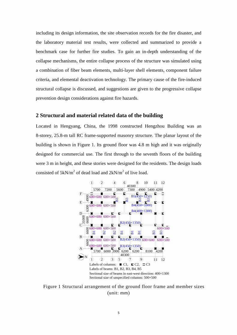
2.2 Masonry structure on the first through seventh floors
The upper masonry structure was constructed of hollow concrete blocks. As shown in
Figure 2, the masonry walls were laid out along the central axes of the frame beams
on the ground floor, and an atrium was constructed at the center of the building. The
masonry wall thickness was 190 mm. The design compressive strengths of the
concrete blocks and the cement mortars are summarized in Table 2. The on-site
rebound hammer test and the laboratory compressive test of the drilled cores indicated
that the design requirements of the actual strengths were met [24, 29-31]. The tie columns
and the bond beams were arranged on every floor to confine the masonry walls. Their
sectional dimension was 190 ×190 mm, with four longitudinal reinforcing bars having
diameters of 12 mm. 1 2 4 6 8
1 2 3 5 7 9
F
E
D
C
B
A
403005700 7200 5600 7300 4900 5400 4200
403005700 6000 3900 6200 6200 8100 4200
3100
066
0066
0066
0063
0049
00
10 11 12
11 12
Atrium (2nd-8th floors)
N
Bond beamsTie columns Figure 2 The arrangement of the bond beams and tie columns of the masonry
on the first through seventh floors (unit: mm)
Table 2 Design compressive strength of concrete blocks and mortar
Floor Design compressive strength of concrete block
(MPa)
Design compressive strength of mortar
(MPa)
1 20 10
2 20 7.5
3 10 7.5
4-6 10 5
7 10 2.5
Page 9
8
3 Fire related data of the building
The first-year occupation of the ground floor of the Hengzhou Building comprised an
herbal medicine wholesale market. However, in 1999, it was banned under the
market’s consolidation. After that, its function underwent a number of changes,
namely, to a warehouse, to a store for chemical materials, such as polyethylene film,
nylon rope, linoleum, etc. (which are flammable materials with high levels of heat
release). The building came under attack from a fire that struck on the morning (about
5:30 am) of November 3rd, 2003. The site observation of the building’s debris, and the
interview of the witnesses, indicated that the fire propagated quickly through a large
portion of the ground floor, while the upper floors were not affected. The fire lasted
for more than 3 hours, with continuous combustion, due to the large fire load. The
building finally collapsed at 8:38 am.
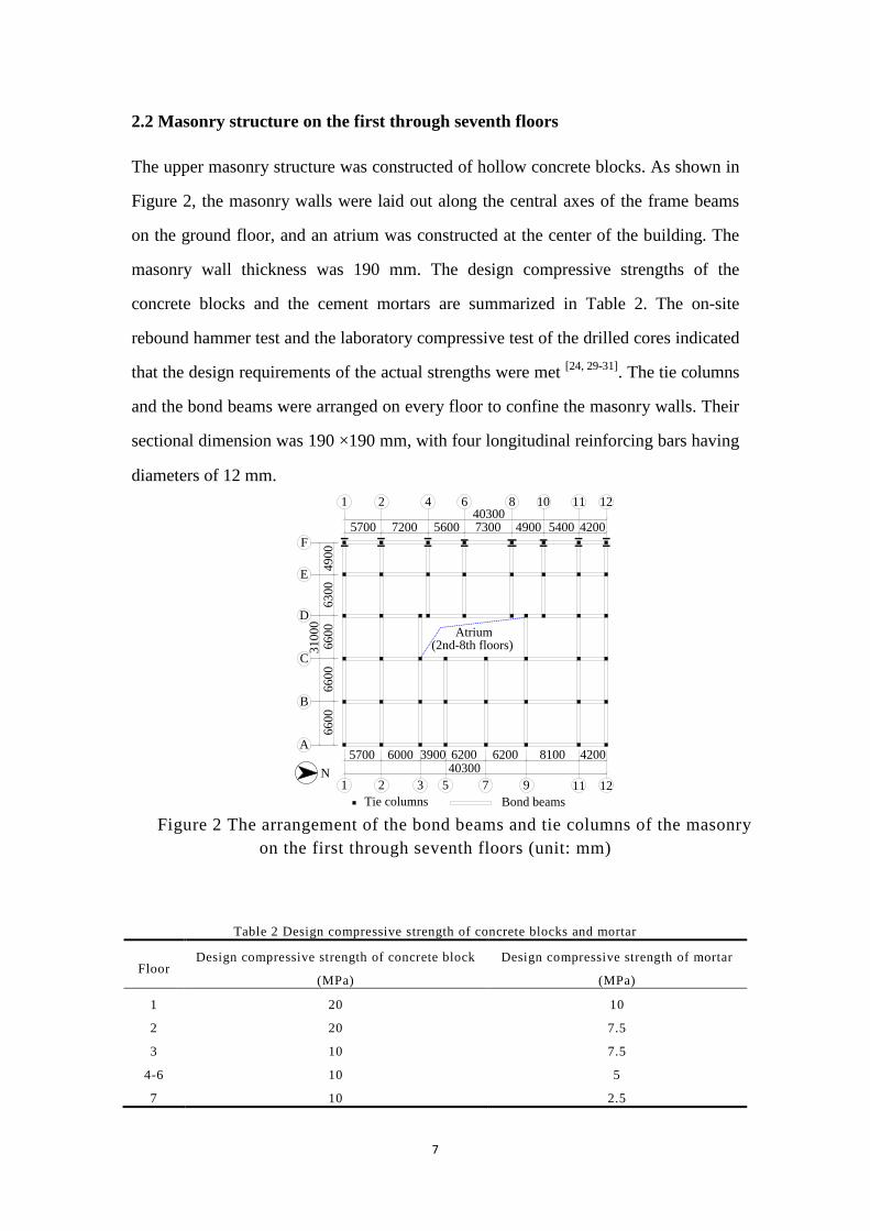
An accurate time-history of the temperature distribution within the building was not
recorded due to the lack of warning about the fire incident and the unavailability of a
measurement tool. Such a tool had not been used in the small city for more than a
decade. However, the fire related data was deduced from the site investigation and the
laboratory test on the materials post-fire. The steel samples exposed to the fire were
tested by the National Analysis Center for Iron and Steel (NACIS) of China using the
metallographic analysis method [32]. The test report indicated that the reinforcing steels
in some of the structural components were over-sintered but not melted. Given that
the sintering and melting temperatures of reinforcing steels are 1250 ºC and 1500 ºC,
respectively, the highest temperature of steel was deduced to have between these two
values. Further, based on the test data of the steel samples from different locations
within the building, the temperature distribution on the ground floor of the building
was determined, as shown in Figure 3. About 45.9% of the bottom RC frame suffered
a high temperature in excess of 800ºC (the area was 573.46m2 of the floor area
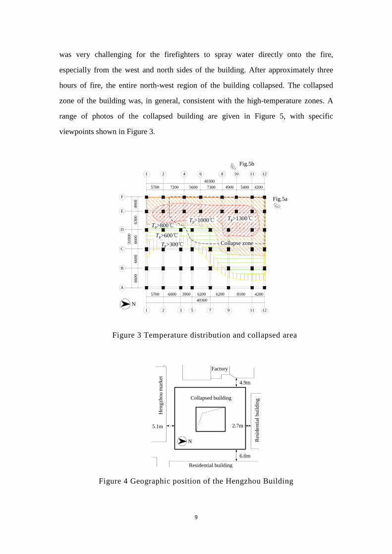
1249.3m2 (=45.9%)). Due to congestion by the surrounding buildings (Figure 4), it
Page 10
9
was very challenging for the firefighters to spray water directly onto the fire,
especially from the west and north sides of the building. After approximately three
hours of fire, the entire north-west region of the building collapsed. The collapsed
zone of the building was, in general, consistent with the high-temperature zones. A
range of photos of the collapsed building are given in Figure 5, with specific
viewpoints shown in Figure 3.
Tp>1300℃Tp>1000℃Tp>800℃
Tp>300℃Tp>600℃
Collapse zone
N
Fig.5a
1 2 4 6 8 10 11 12
1 2 3 5 7 9 11 12
F
E
D
C
B
A
403005700 7200 5600 7300 4900 5400 4200
403005700 6000 3900 6200 6200 8100 4200
3100
066
0066
0066
0063
0049
00
Fig.5b
Figure 3 Temperature distribution and collapsed area
Collapsed building
N
4.9m
2.7m5.1m
6.0m
Factory
Residential building
Res
iden
tial b
uild
ing
Hen
gzho
u m
arke
t
Figure 4 Geographic position of the Hengzhou Building
Page 11
10
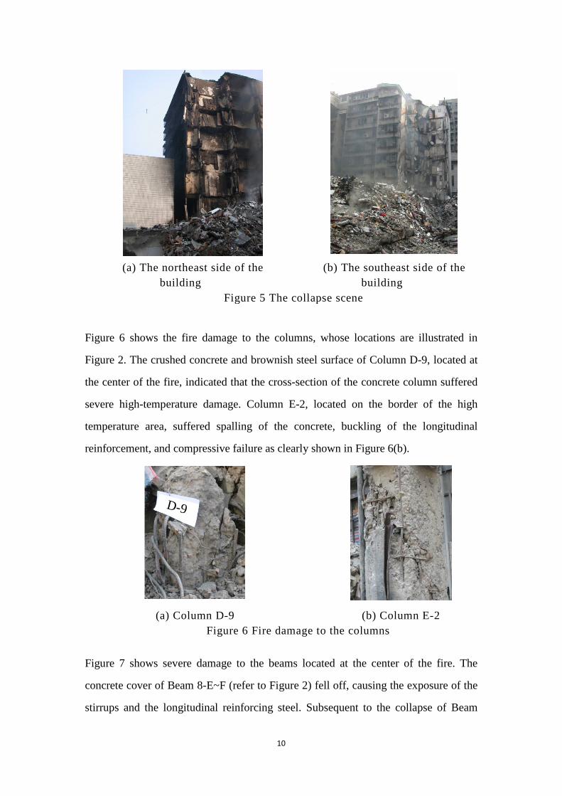
(a) The northeast side of the
building (b) The southeast side of the
building Figure 5 The collapse scene
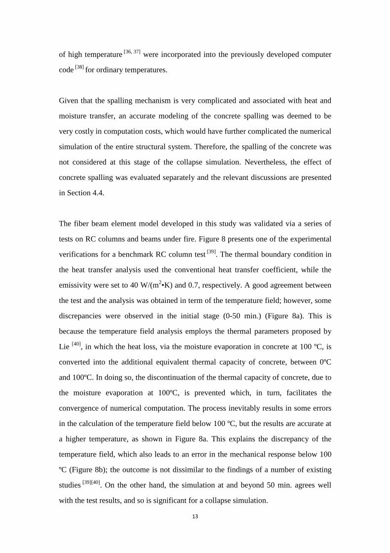
Figure 6 shows the fire damage to the columns, whose locations are illustrated in
Figure 2. The crushed concrete and brownish steel surface of Column D-9, located at
the center of the fire, indicated that the cross-section of the concrete column suffered
severe high-temperature damage. Column E-2, located on the border of the high
temperature area, suffered spalling of the concrete, buckling of the longitudinal
reinforcement, and compressive failure as clearly shown in Figure 6(b).
D-9
(a) Column D-9 (b) Column E-2
Figure 6 Fire damage to the columns
Figure 7 shows severe damage to the beams located at the center of the fire. The
concrete cover of Beam 8-E~F (refer to Figure 2) fell off, causing the exposure of the
stirrups and the longitudinal reinforcing steel. Subsequent to the collapse of Beam
Page 12
11
10-D~E, the reinforcing steels were exposed, and some degree of spalling was
observed. The metallographic analysis of the reinforcement indicated that the highest
temperature of the steel was between 1250 ºC and 1500 ºC, as described above.
(a) Beam 8-E~F (b) Beam 10-D~E
Figure 7 Fire damage to the beams
Based on the degree of damage to the columns and beams, the preliminarily site
investigation concluded that damage of Columns E-8, E-10, E-11, D-9, and D-11 on
the ground floor (refer to Figure 1) occurred due to very high temperature exposure,
which is believed to have triggered the progressive collapse of the upper masonry
structure. The columns were designed to resist a normal fire in accordance with the
requirements of the design code [33], regulated for commercial buildings. However the
occupation of the ground floor of the building was changed to a warehouse filled with
a large amount of flammable materials. Hence, the actual fire load developing at the
time of the accident was extremely high, higher than originally considered acceptable
in the design. The extraordinary fire load, covering a large area with a very high
temperature, is considered to be the primary reason for the initial damage to the
ground floor columns. In addition, the spalling of the concrete cover, and the
construction error at the connections between the slabs and the RC frame, all
accelerated the damaged to the columns.
4 Numerical simulation
To gain an in-depth understanding of the collapse mechanisms of the building under
fire, a numerical simulation of the collapse process was performed using the finite
element method.
Page 13
12
4.1 Modeling details
Given the complexity of the actual structure and the fire development process, the
simplified structural model and the fire scenario was considered to perform an
efficient analysis. The analysis was achieved by modeling the structure with fiber
beam elements and shell elements, while the fire development was represented by a
standard heating curve. The fracture of the structural components was simulated by
the component failure criteria, which was associated with the element deactivation
technique. Details of the numerical model are introduced in the following
sub-sections.
4.1.1 Numerical model for the ground floor RC frame
The structure of the ground floor of the Hengzhou Building was in the form of a RC
frame. A fiber beam element model, which takes into account the effect of high
temperature, was developed to simulate the RC beams and columns on the ground
floor. Existing research has demonstrated that this type of element model can simulate
fire-induced mechanical behavior of RC elements with various cross sections [34].
Using this model, only six fiber beam elements along the longitudinal direction were
required to represent a beam or a column, resulting in high computational efficiency.
This outcome, in turn, facilitated an effective analysis of the entire structure [35].
In the developed model, the cross-section of the beam or column was divided into a
number of concrete and steel fibers that satisfied the plane-in-plane assumption.
Different temperatures were assigned to different fibers to account for the
non-uniform temperature distribution over the cross-section of the beams and columns.
For each typical section of the beams and columns of the Hengzhou Building, which
had different cross-sectional dimensions, and which were exposed to fire action with
different maximum temperatures, the heat transfer analysis was conducted to calculate
the time history of the temperature in each fiber of the section. The coupled
thermo-mechanical constitutive laws of concrete and steel that account for the effect
Page 14
13
of high temperature [36, 37] were incorporated into the previously developed computer
code [38] for ordinary temperatures.
Given that the spalling mechanism is very complicated and associated with heat and
moisture transfer, an accurate modeling of the concrete spalling was deemed to be
very costly in computation costs, which would have further complicated the numerical
simulation of the entire structural system. Therefore, the spalling of the concrete was
not considered at this stage of the collapse simulation. Nevertheless, the effect of
concrete spalling was evaluated separately and the relevant discussions are presented
in Section 4.4.
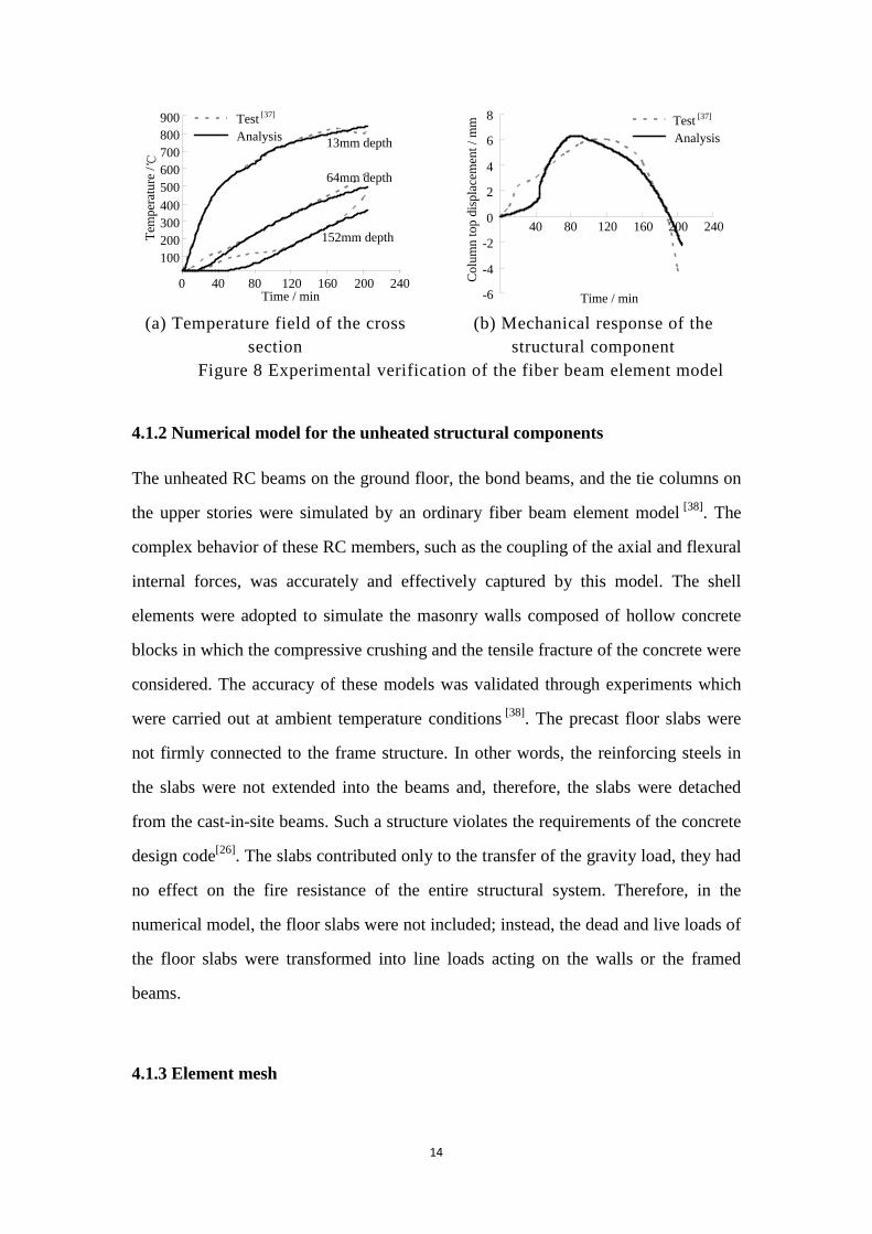
The fiber beam element model developed in this study was validated via a series of
tests on RC columns and beams under fire. Figure 8 presents one of the experimental
verifications for a benchmark RC column test [39]. The thermal boundary condition in
the heat transfer analysis used the conventional heat transfer coefficient, while the
emissivity were set to 40 W/(m2•K) and 0.7, respectively. A good agreement between
the test and the analysis was obtained in term of the temperature field; however, some
discrepancies were observed in the initial stage (0-50 min.) (Figure 8a). This is
because the temperature field analysis employs the thermal parameters proposed by
Lie [40], in which the heat loss, via the moisture evaporation in concrete at 100 ºC, is
converted into the additional equivalent thermal capacity of concrete, between 0ºC
and 100ºC. In doing so, the discontinuation of the thermal capacity of concrete, due to
the moisture evaporation at 100ºC, is prevented which, in turn, facilitates the
convergence of numerical computation. The process inevitably results in some errors
in the calculation of the temperature field below 100 ºC, but the results are accurate at
a higher temperature, as shown in Figure 8a. This explains the discrepancy of the
temperature field, which also leads to an error in the mechanical response below 100
ºC (Figure 8b); the outcome is not dissimilar to the findings of a number of existing
studies [39][40]. On the other hand, the simulation at and beyond 50 min. agrees well
with the test results, and so is significant for a collapse simulation.
Page 15
14
100200300400500600700800900
0 40 80 120 160 200 240Time / min
Tem
pera
ture
/ ℃
Test [37]
Analysis 13mm depth
64mm depth
152mm depth
-6
-4
-2
0
2
4
6
8
40 80 120 160 200 240
Time / min
Col
umn
top
disp
lace
men
t / m
m
AnalysisTest [37]
(a) Temperature field of the cross
section (b) Mechanical response of the
structural component Figure 8 Experimental verification of the fiber beam element model
4.1.2 Numerical model for the unheated structural components
The unheated RC beams on the ground floor, the bond beams, and the tie columns on
the upper stories were simulated by an ordinary fiber beam element model [38]. The
complex behavior of these RC members, such as the coupling of the axial and flexural
internal forces, was accurately and effectively captured by this model. The shell
elements were adopted to simulate the masonry walls composed of hollow concrete
blocks in which the compressive crushing and the tensile fracture of the concrete were
considered. The accuracy of these models was validated through experiments which
were carried out at ambient temperature conditions [38]. The precast floor slabs were
not firmly connected to the frame structure. In other words, the reinforcing steels in
the slabs were not extended into the beams and, therefore, the slabs were detached
from the cast-in-site beams. Such a structure violates the requirements of the concrete
design code[26]. The slabs contributed only to the transfer of the gravity load, they had
no effect on the fire resistance of the entire structural system. Therefore, in the
numerical model, the floor slabs were not included; instead, the dead and live loads of
the floor slabs were transformed into line loads acting on the walls or the framed
beams.
4.1.3 Element mesh
Page 16
15
The element mesh and connections are shown in Figure 9. Each RC beam/column on
the ground floor was simulated by six fiber beam elements, considering the high
temperature effect on the material behavior. Each bond RC beam/tie column on the
upper stories was modeled by six normal fiber beam elements. Each masonry wall
was represented by a 6×6 element mesh in which some elements were removed to
simulate windows or doors.
Fixed to the ground
Gravity column
Window or door
Fiber beam element incorporated high temperature material laws
Ground floor(RC Frame)
Second floor(Masonry wall)
Gravity beam
Bond RC beam
Tie RC column
Masonry wall
Normal fiber beam element
Normal shell element
Common nodes
Figure 9 Modeling method of the Hengzhou Building
4.1.4 Component failure criteria
During the structural collapse, damage and fracture occurred in some members,
causing a redistribution of the internal forces. By establishing the appropriate failure
criteria for the structural components under high temperature, the fracture of these
components was simulated by using the “elemental deactivation” technique[41].
For the RC columns and beams exposed to fire, the tensile failure of the
reinforcement occurred when its ultimate tensile strain was reached at a high
temperature. Similarly, the compressive failure of concrete occurred when its
ultimate crushing strain was reached. As defined in this work, the beam or column
sectional failure was reached upon the fracturing of all the steel fibers or the
crushing of all the concrete fibers within that section, respectively. The RC beams
Page 17
16
exhibited bending and tensile capacities under small and large deformations,
respectively, which contributed to the collapse resistance of the building [42-44].
Similarly, bending and compressive mechanisms also existed in the columns under
small and large deformations, respectively. The failure criteria allowed the RC
beams and columns to undergo both small and large deformations, but they only
failed with the large deformations. When a structural member reached its failure
criterion, the corresponding element was subsequently removed from the finite
element model using the “elemental deactivation” technique. As a result, the internal
force of the removed element was also released [41]. The ultimate strains on the steel
and concrete at high temperatures, suggested by Guo and Shi [37], were adopted in
the current work to determine the failure of the material fibers.
Simultaneously, the failure criteria for the unheated RC components followed the
work of Lu et al. [38]. For the masonry walls, consisting of concrete blocks, failure
was considered to have occurred when the crushing strain of the concrete or mortar
was reached, and the corresponding element was subsequently deactivated.
4.1.5 Simplification of fire development
The fire dynamics of a real fire is highly complex. For this reason, an accurate
time-history of temperature distribution in the current situation could not be recorded,
as previously discussed. To facilitate the analysis, a simplified continuous heating
process was assumed in which the traveling fire[45] was not considered due to the
observed rapid spread of fire on the ground floor. This was also based on the
observation that the building collapsed during continuing violent combustion. In
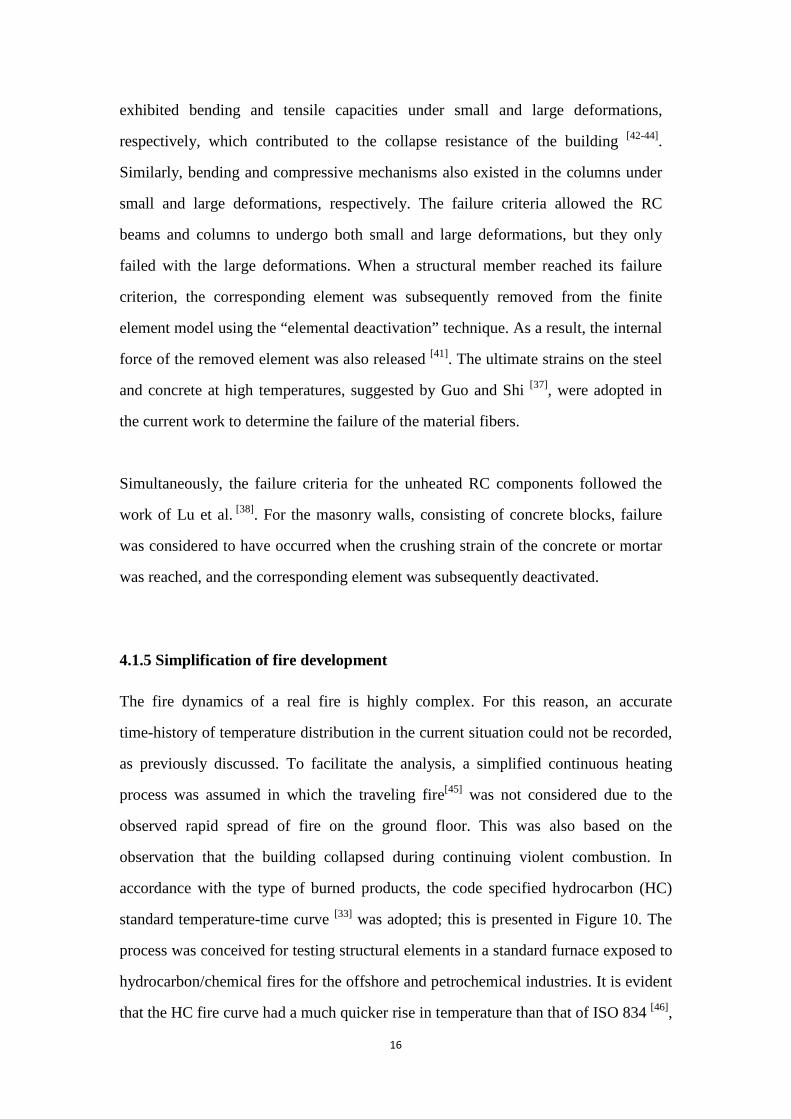
accordance with the type of burned products, the code specified hydrocarbon (HC)
standard temperature-time curve [33] was adopted; this is presented in Figure 10. The
process was conceived for testing structural elements in a standard furnace exposed to
hydrocarbon/chemical fires for the offshore and petrochemical industries. It is evident
that the HC fire curve had a much quicker rise in temperature than that of ISO 834 [46],
Page 18
17
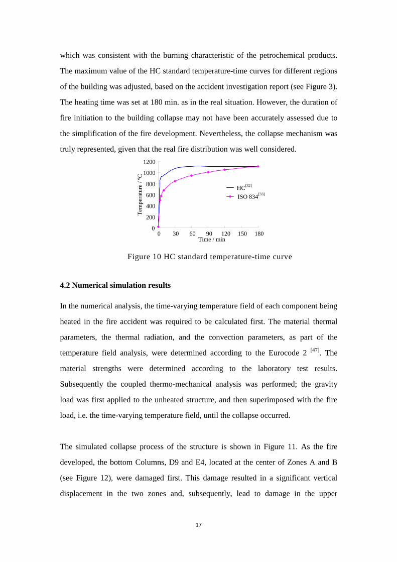
which was consistent with the burning characteristic of the petrochemical products.
The maximum value of the HC standard temperature-time curves for different regions
of the building was adjusted, based on the accident investigation report (see Figure 3).
The heating time was set at 180 min. as in the real situation. However, the duration of
fire initiation to the building collapse may not have been accurately assessed due to
the simplification of the fire development. Nevertheless, the collapse mechanism was
truly represented, given that the real fire distribution was well considered.
0
200
400
600
800
1000
1200
0 30 60 90 120 150 180Time / min
Tem
pera
ture
/ ºC
HCISO 834
[32]
[33]
Figure 10 HC standard temperature-time curve
4.2 Numerical simulation results
In the numerical analysis, the time-varying temperature field of each component being
heated in the fire accident was required to be calculated first. The material thermal
parameters, the thermal radiation, and the convection parameters, as part of the
temperature field analysis, were determined according to the Eurocode 2 [47]. The
material strengths were determined according to the laboratory test results.
Subsequently the coupled thermo-mechanical analysis was performed; the gravity
load was first applied to the unheated structure, and then superimposed with the fire
load, i.e. the time-varying temperature field, until the collapse occurred.
The simulated collapse process of the structure is shown in Figure 11. As the fire
developed, the bottom Columns, D9 and E4, located at the center of Zones A and B
(see Figure 12), were damaged first. This damage resulted in a significant vertical
displacement in the two zones and, subsequently, lead to damage in the upper
Page 19
18
masonry walls (Figures 11a and 11b). As the fire developed further, an initial collapse
occurred in Zones A and B (Figure 11c), which altered the load transfer path of the
entire structure and triggered the collapse of the adjacent areas, as shown in Figure
11d. A comparison of Figure 11d and Figure 3 demonstrates that the simulated
collapse area agrees well with the actual one. Moreover, only damages in Zone A
were observed from the site investigation, whereas damages in Zone B were identified
from the numerical simulation. This outcome implies that numerical simulation is a
powerful analysis tool for fire safety research. In the current numerical study, a total
of 23,742 elements were used; this involved five hours computational time on a single
CPU desktop. The proposed modeling method was highly efficient.
D9 E4
(a) Local damage in Zone A (88 min) (b) Local damage in Zone B (89 min)
Actual collapse
area (c) Partial collapse in Zones A and B
(109 min) (d) Collapse in a wide range of areas
(123 min) Figure 11 Simulation of the fire-induced collapse process
The simulated collapse process revealed that the initial cause of the progressive
collapse was the destruction of Columns D9 and E4, located at the center of Zones A
Page 20
19
and B (see Figure 12). The collapse occurred due to the following three factors. First,
the fire temperature in these zones was significantly higher (greater than 800 ºC) than
the other regions. As shown in Figure 3, Columns D9 and E4 reached a maximum
temperature of 1300 ºC. Therefore, the fire damage to these two zones was more
severe than in the remaining part of the structure. Two, the structural planar layout for
Columns D9 and E4 carried a larger gravity load than did the other components (the
shaded part of Figure 12), making them more vulnerable to fire. Third, the structural
arrangements of Zones A and B were more complex than those of the other areas. The
gravity load of the upper walls (4-E~D and 10-E~D), initially acting on the secondary
beams, was transferred to the main girders (3~5-D and 9~11-D), and then to the
columns. Thus, these structural elements appeared to exhibit more complicated
internal force characteristics which were more vulnerable to damaged under the fire
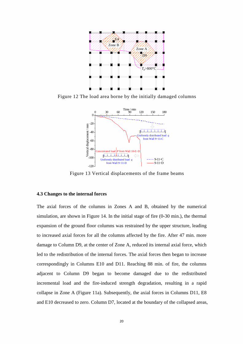
condition. Taking Beam 9~11-D and its parallel Beam 9~11-C in Zone A as an
example, the vertical displacements and the mechanisms of these two beams, shown
in Figure 13, had an identical longitudinal span (8.1m) and supported the slabs with
similar widths (12.9m and 13.2m). This situation lead to near uniformly distributed
gravity loads q acting on the beams. However, an additional concentrated load P
transferred from the upper Wall 10-E~D also acted on Beam 9~11-D. As a result,
larger internal forces (i.e. shear force and bending moment) developed in Beam
9~11-D in comparison to Beam 9~11-C, and, in turn, induced a lager deformation, as
shown in Figure 13. Moreover, the displacement of Beam 9~11-D reversed at about
88 min.; this was due to the load redistribution of the adjacent columns as a result of
the high temperature actions (discussed in the following section). Given the
abovementioned reasons, Zones A and B were the most vulnerable regions within the
structure to initiate a collapse under fire.
Page 21
20
Zone B Zone A
Tp>800°C
D9
E4
Figure 12 The load area borne by the initially damaged columns
0 30 60 90 120 150 180
-120
-100
-80
-60
-40
-20
0
Time / min
Verti
cal d
ispla
cem
ent /
mm
9-11~C 9-11~D
Uniformly distributed load q from Wall 9~11-C
Uniformly distributed load q from Wall 9~11-D
Concentrated load P from Wall 10-E~D
Figure 13 Vertical displacements of the frame beams
4.3 Changes to the internal forces
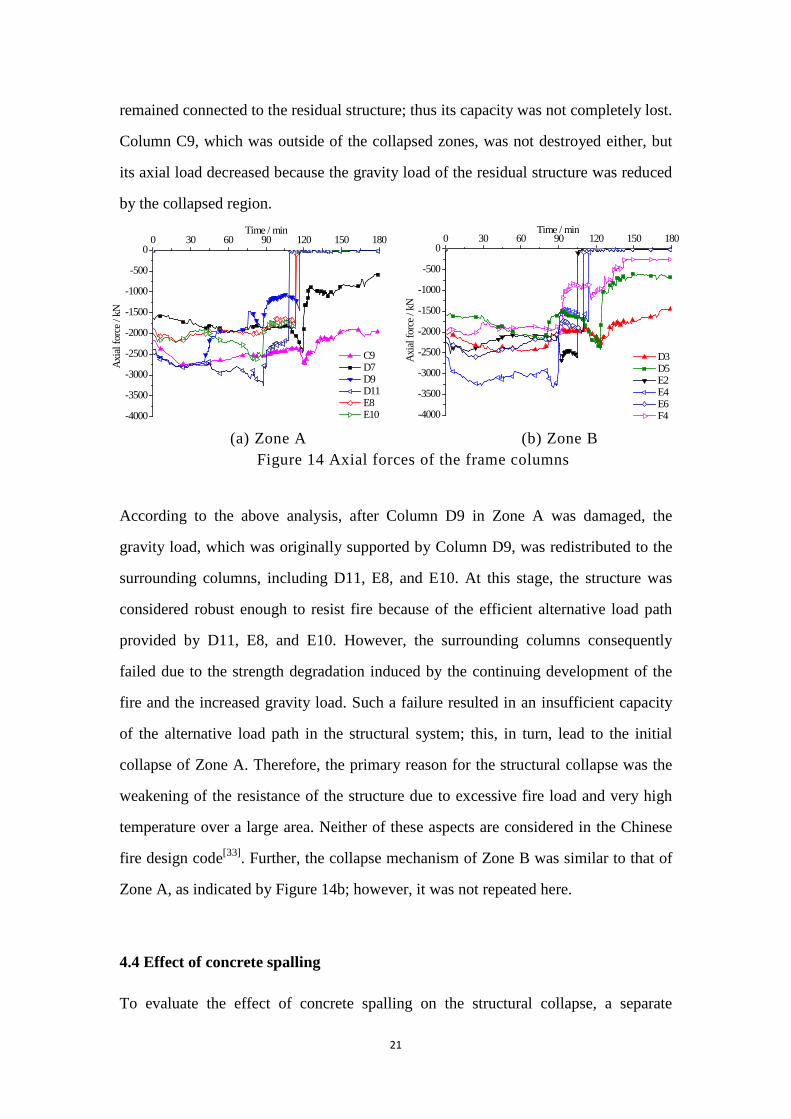
The axial forces of the columns in Zones A and B, obtained by the numerical
simulation, are shown in Figure 14. In the initial stage of fire (0-30 min.), the thermal
expansion of the ground floor columns was restrained by the upper structure, leading
to increased axial forces for all the columns affected by the fire. After 47 min. more
damage to Column D9, at the center of Zone A, reduced its internal axial force, which
led to the redistribution of the internal forces. The axial forces then began to increase
correspondingly in Columns E10 and D11. Reaching 88 min. of fire, the columns
adjacent to Column D9 began to become damaged due to the redistributed
incremental load and the fire-induced strength degradation, resulting in a rapid
collapse in Zone A (Figure 11a). Subsequently, the axial forces in Columns D11, E8
and E10 decreased to zero. Column D7, located at the boundary of the collapsed areas,
Page 22
21
remained connected to the residual structure; thus its capacity was not completely lost.
Column C9, which was outside of the collapsed zones, was not destroyed either, but
its axial load decreased because the gravity load of the residual structure was reduced
by the collapsed region.
0 30 60 90 120 150 180
-4000
-3500
-3000
-2500
-2000
-1500
-1000
-500
0
Axial
forc
e / k
N
Time / min
C9 D7 D9 D11 E8 E10
0 30 60 90 120 150 180
-4000
-3500
-3000
-2500
-2000
-1500
-1000
-500
0
Time / min
Axia
l for
ce /
kN
D3 D5 E2 E4 E6 F4
(a) Zone A (b) Zone B Figure 14 Axial forces of the frame columns
According to the above analysis, after Column D9 in Zone A was damaged, the
gravity load, which was originally supported by Column D9, was redistributed to the
surrounding columns, including D11, E8, and E10. At this stage, the structure was
considered robust enough to resist fire because of the efficient alternative load path
provided by D11, E8, and E10. However, the surrounding columns consequently
failed due to the strength degradation induced by the continuing development of the
fire and the increased gravity load. Such a failure resulted in an insufficient capacity
of the alternative load path in the structural system; this, in turn, lead to the initial
collapse of Zone A. Therefore, the primary reason for the structural collapse was the
weakening of the resistance of the structure due to excessive fire load and very high
temperature over a large area. Neither of these aspects are considered in the Chinese
fire design code[33]. Further, the collapse mechanism of Zone B was similar to that of
Zone A, as indicated by Figure 14b; however, it was not repeated here.
4.4 Effect of concrete spalling
To evaluate the effect of concrete spalling on the structural collapse, a separate
Page 23
22
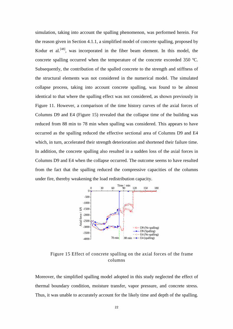
simulation, taking into account the spalling phenomenon, was performed herein. For
the reason given in Section 4.1.1, a simplified model of concrete spalling, proposed by
Kodur et al.[48], was incorporated in the fiber beam element. In this model, the
concrete spalling occurred when the temperature of the concrete exceeded 350 ºC.
Subsequently, the contribution of the spalled concrete to the strength and stiffness of
the structural elements was not considered in the numerical model. The simulated
collapse process, taking into account concrete spalling, was found to be almost
identical to that where the spalling effect was not considered, as shown previously in
Figure 11. However, a comparison of the time history curves of the axial forces of
Columns D9 and E4 (Figure 15) revealed that the collapse time of the building was
reduced from 88 min to 78 min when spalling was considered. This appears to have
occurred as the spalling reduced the effective sectional area of Columns D9 and E4
which, in turn, accelerated their strength deterioration and shortened their failure time.
In addition, the concrete spalling also resulted in a sudden loss of the axial forces in
Columns D9 and E4 when the collapse occurred. The outcome seems to have resulted
from the fact that the spalling reduced the compressive capacities of the columns
under fire, thereby weakening the load redistribution capacity.
0 30 60 90 120 150 180
-4000
-3500
-3000
-2500
-2000
-1500
-1000
-500
0
78 min
Axia
l for
ce /
kN
Time / min
D9 (No spalling) D9 (Spalling) E4 (No spalling) E4 (spalling)88 min
Figure 15 Effect of concrete spalling on the axial forces of the frame
columns
Moreover, the simplified spalling model adopted in this study neglected the effect of
thermal boundary condition, moisture transfer, vapor pressure, and concrete stress.
Thus, it was unable to accurately account for the likely time and depth of the spalling.
Page 24
23
Hence, the above discussion on the spalling effect is case specific to this study.
Accordingly, the findings cannot be generalized to other cases unless an advanced
spalling model is developed which is suitable for global analyses of entire structural
systems.
5 Progressive collapse prevention design considerations against fire
A number of progressive collapse prevention design considerations against fire are
presented here. First, the key structural components in a system refer to those that
bear a large gravity load while being vulnerable to fire. Such key components, as
Columns D9 and E4 in the Hengzhou Building, greatly affect the collapse resistance
of the RC frame in a fire. Subsequent to the failure of these components, their
originally supported gravity load is then transferred to a large, unbalanced load acting
on the residual structure, which also suffers fire-induced damages. The capacity of the
residual structure to redistribute the internal forces is continuously weakened with the
fire’s development. These factors may cause an unbalanced load beyond the
resistance of the residual structure, thereby triggering a progressive collapse.
The initial local failure of several structural members in a building structure, due to
accidental events, such as fire, gas explosions, or vehicle impact, may propagate, from
member to member, and eventually result in the collapse of a large portion of or the
entire structural system, described as a progressive collapse[49]. In the conventional
progressive collapse design codes[50,51], the alternative load path method and the local
resistance method are recommended to enhance the robustness of the building
structures. For the alternative load path method, the initial local damage is allowed,
but the consequent progressive collapse is prevented, by enhancing the remaining
structures to bridge over the initial local damage. In contrast, the local resistance
method is much simpler in which the bending and shear capacities of the regulated
structural members is enhanced to satisfy some special requirements. However, the
characteristic of fire-induced progressive collapse is not considered in these
Page 25
24
regulations. Based on the above discussion, when a building structure is exposed to an
excessive fire covering a large area, the alternative load path for a key element may
also be weakened. As a consequence, the alternative load path method may not be
reliable for this situation. In addition, the local resistance method only requires
enhancement of the capacity of the perimeter columns and load-bearing walls of the
bottom two stories under normal temperature [51]. However, the fire resistance of the
interior members, which are more vulnerable to fire-induced collapse prior to other
structural members, was not considered in the present study. Therefore, an efficient
method to prevent the progressive collapse of a building structure exposed to a fire is
to determine the key components in the structural system and protect them from being
damaged by increasing its high-strength redundancy, or installing fire protections.
Second, for buildings with high fire risks, the special design of the fire compartment
is required to partition the large structural space into several smaller spaces to prevent
the spread of the fire throughout a large part of the building. In accordance with the
analysis of the Hengzhou Building, if the RC frame on the ground floor was exposed
to a large, severe fire, progressive collapse, it is unlikely to be prevented following the
initial local damage. An optimized fire compartment also helps to control the scope of
the fire in a building and, in turn, reduces the fire damages to the overall structure.
However, the existing regulation about the fire compartment may not be effective in
preventing the fire-induced progressive collapse of a building structure. The
maximum area of the fire compartment zone varied from 500m2 to 2500m2, which is
regulated in the existing code[33], based on the function and safety level of the building.
However, these dimension are not targeted for the prevention of fire-induced
progressive collapse. For example, in the Hengzhou Building, the area of the ground
floor exposed to fire exceeding 300 ºC was approximately 839.44 m2, which was still
less than 1000 m2 (i.e. the minimum requirement for warehouses). As shown in the
current case study, a building will still collapse even it complies with the fire
compartment requirement. Therefore, the fire compartment needs to be further
Page 26
25
investigated to consider fire-induced progressive collapse.
Third, the integration and connection of the structural members are important to the
robustness of the structural system in a fire. In the Hengzhou Building, the precast
slabs were not firmly tied into the RC frame, which violated the corresponding design
code[26]. If the slabs were integrated with the RC frame, the capacity and restraint of
the columns would have been improved; in turn, this would have reduced the
structural deformation and prevented or delayed the collapse of the critical columns
on the ground floor. Consequently, improving the integration and connection of the
structural members are actions that would mitigate the progressive collapse of
building structures in fire.
6 Conclusions
In this paper, the fire-induced collapse of an 8-storey RC-frame-supported masonry
building is reported and modeled. Information on the structure and the fire scenario
has been presented. Using the proposed numerical modeling technique, the
fire-induced collapse of the building was analyzed. The preliminary results indicate
that the collapse of the building was likely due to the severe fire to which it was
exposed (about 45.9% of the bottom storey of the RC frame was predicted to have
experienced temperatures in excess of 800ºC, and its central area was predicted to
have reached almost 1300ºC). Such a situation was thought to have significantly
weakened its residual capacity and ability to redistribute the unbalanced gravity loads.
Two vulnerable zones surrounding Columns D9 and E4 were severely damaged and
may have triggered the progressive collapse of the entire building. The initial damage
of these zones may have been due to very high temperature exposure, larger gravity
loads, and a complex load transfer mechanism. The influence of concrete spalling on
the collapse simulation is also discussed, although the discussion is specific to the
particular case of this study where a simplified spalling model is used and, as such,
should not be treated as a generalized conclusion. Nevertheless, the numerical
Page 27
26
analysis outcomes have provided practical design considerations on the key structural
components, the fire compartments, and the structural robustness are given which
should aid in the prevention of the fire-induced progressive collapse of RC frame
structures.
References
[1] Building Research Establishment Ltd (2003) Client report: results and observations from
full-scale fire test at BRE Cardington (Client report number 215-741). Cardington
[2] Sun R, Huang ZH, Burgess IW. (2012) Progressive collapse analysis of steel structures under
fire conditions. Eng Struct. 34(2): 400-413
[3] Gillie M, Usmani AS, Rotter JM (2001) A structural analysis of the first Cardington test. J
Constr Steel Res. 57(6): 581-601
[4] Gillie M, Usmani AS, Rotter JM (2002) A structural analysis of the Cardington British Steel
Corner Test. J Constr Steel Res. 58(4): 427-442
[5] Lamont S, Usmani AS, Drysdale DD (2001) Heat transfer analysis of the composite slab in
the Cardington frame fire tests. Fire Saf J. 36(8): 815-839
[6] Mostafaei H (2013) Hybrid fire testing for assessing performance of structures in
fire-Application. Fire Saf J. 56(2): 30-38
[7] Robert F; Collignon C, Scalliet M (2013) Large scale fire test on tunnel segment: Real
boundary conditions in order to evaluate spalling sensitivity and fire resistance. In:
Proceedings of the 3rd International Workshop on Concrete Spalling due to Fire Exposure,
Paris, France
[8] Drysdale D (2011) An introduction to fire dynamics. John Wiley & Sons, Inc., New York.
[9] Franssen JM (2005) SAFIR: a thermal/structural program modelling structures under fire.
Eng J, AISC. 42(3): 143-158
[10] Cai J, Burgess IW, Plank RJ (2003) A generalised steel/reinforced concrete beam-column
element model for fire conditions. Eng Struct. 25(6): 817-833
[11] Gilliea M, Usmani A, Rotter M, O’Connor M (2001) Modelling of heated composite floor
slabs with reference to the Cardington experiments. Fire Saf J. 36(8): 745-767
Page 28
27
[12] Sanad AM, Usmani A, Rotter JM, O’Connor M (2000) Composite beams in large buildings
under fire: numerical modelling and structural behaviour. Fire Saf J. 35(3): 165-188
[13] Yin YZ, Wang YC (2004) A numerical study of large deflection behaviour of restrained
steel beams at elevated temperatures. J Constr Steel Res. 60(7): 1029-1047
[14] Usmani AS, Chung YC, Torero JL (2003) How did the WTC towers collapse: a new theory.
Fire Saf J. 38(6): 501-533
[15] Quintiere JG, di Marzo M, Becker R (2002) A suggested cause of the fire-induced collapse
of the World Trade Towers. Fire Saf J. 37(7): 707-716
[16] National Institute of Standards and Technology (2005) Final report on the collapse of the
world trade center towers. Gaithersburg
[17] McAllister T, Sadek F, Gross JL, Averill JD, Gann RG. (2013) Overview of the structural
design of world trade center 1, 2, and 7 buildings. Fire Tech. 49(3): 587-613
[18] Kotsovinos P, Usmani A. (2013) The world trade center 9/11 disaster and progressive
collapse of tall buildings. Fire Tech. 49(3): 741-765
[19] McAllister TP, Gross JL, Sadek F, Kirkpatrick S, MacNeill RA, Zarghamee M, Erbay OO,
Sarawit AT (2013) Structural response of world trade center buildings 1, 2 and 7 to impact
and fire damage. Fire Tech. 49(3): 709-739
[20] Capote JA, Alvear D, Lazaro M, Espina P, Fletcher I, Welch S, Torero JL (2006) Analysis
of thermal fields generated by natural fires on the structural elements of Tall Buildings. In:
Proceedings of the International Congress on Fire Safety in Tall Buildings, Santander, Spain
[21] Fletcher IA, Borg A, Hitchen N, Welch S (2006) Performance of concrete in fire: a review
of the state of the art, with a case study of the Windsor tower fire. In: Proceedings of the 4th
International Workshop in Structures in Fire, Aveiro, Portugal
[22] Flint G, Lamont S, Lane B, Sarrazin H, Lim L, Rini D, Roben C (2013) Recent lessons
learned in structural fire engineering for composite steel structures. Fire Tech. 49(3):
767-792
[23] Lamont S, Lane B, Flint G, Usmani A (2006) Behavior of structures in fire and real design -
a case study. J Fire Prot Eng. 16(2): 5-35.
Page 29
28
[24] The Ministry of Construction of the People's Republic of China (2001) Technical
specification for inspecting of concrete compressive strength by rebound method (JGJ/T
23-2001). Beijing
[25] The Ministry of Construction of the People's Republic of China (1988) Technical
specification for testing concrete strength with drilled core (CECS 03:88). Beijing; 1988
[26] The Ministry of Construction of the People's Republic of China (1989) Code for design of
concrete structures (GBJ 10-89). Beijing
[27] General Administration of Quality Supervision, Inspection and Quarantine of the People's
Republic of China (1988) Hot rolled ribbed steel bar for the reinforcement of concrete (GB
1499-98). Beijing
[28] General Administration of Quality Supervision, Inspection and Quarantine of the People's
Republic of China (1991) Hot rolled low carbon steel wire rods (GB/T 701-91). Beijing
[29] State Bureau of Building Materials Industry (2000) Precast concrete paving units (JC/T
446-2000). Beijing
[30] State Bureau of Building Materials Industry (1997). Normal concrete small hollow block
(GB 8239-1997). Beijing
[31] The Ministry of Construction of the People's Republic of China (2000) Technical standard
for site testing of engineering (GB/T 50315-2000). Beijing
[32] Vander Voort GF (2004) ASM handbook: volume 9: metallography and microstructures.
ASM International, Novelty.
[33] The Ministry of Construction of the People's Republic of China (2006) Code of design on
building fire protection and prevention (GB50016-2006). Beijing
[34] Xu Y, Wu B (2009) Fire resistance of reinforced concrete columns with L-, T-, and
+-shaped cross-sections. Fire Saf J. 44(6): 869-80
[35] Huang ZH, Burgess IW, Plank RJ (2009) Three-dimensional analysis of reinforced concrete
beam-column structures in fire. J Struct Eng, ASCE. 135(10): 1201-1212
[36] Shi XD, Tan TH, Tan KH (2002) Concrete constitutive relationships under different
stress-temperature paths. J Struct Eng, ASCE. 128(12): 1511-1518
[37] Guo ZH, Shi XD (2003) Behaviour of reinforced concrete at elevated temperatureand its
calculation. Tsinghua University Press. Beijing (in Chinese)
Page 30
29
[38] Lu X, Lu XZ, Guan H, Ye LP (2013) Collapse simulation of reinforced concrete high-rise
building induced by extreme earthquakes. Earthq Eng Struct Dyn. 42(5): 705-723
[39] Lie TT, Irwin RJ (1993) Method to calculate the fire resistance of reinforced concrete
columns with rectangular cross section. ACI Struct J. 90(1): 52-60
[40] Lie TT, Celikkol B (1991) Method to calculate the fire resistance of circular reinforced
concrete columns. ACI Struct J. 88(1): 84-91
[41] MSC Software Corp (2005) MSC.Marc Volume A: Theory and User Information
[42] Li Y, Lu XZ, Guan H, Ye LP (2011) An improved tie force method for progressive collapse
resistance design of reinforced concrete frame structures. Eng Struct. 33(10): 2931-2942
[43] Li Y, Lu XZ, Guan H, Ye LP (2014) An energy-based assessment on dynamic
amplification factor for linear static analysis in progressive collapse design of ductile RC
frame structures. Adv Struct Eng. 17(8): 1217-1225
[44] Li Y, Lu XZ, Guan H, Ye LP (2014) Progressive collapse resistance demand of RC frames
under catenary mechanism. ACI Struct J. 111(5):1225-1234
[45] Law A, Stern-Gottfried J, Gillie M, Rein G (2011) The influence of travelling fires on a
concrete frame. Eng Struct. 33(5): 1635-1642.
[46] International Standard Organization (1999) International standard ISO 834-1: fire resistance
tests - elements of building construction - Part 1: general requirements. Geneva
[47] European Committee for Standardization (2004) Eurocode 2: design of concrete structures.
Part 1-2: general rules structural fire design (EN 1992-1-2). Brussels
[48] Kodur VKR, Wang TC, Cheng FP (2004) Predicting the fire resistance behavior of high
strength concrete columns. Cement Concrete Comp. 26(2): 141-153.
[49] American Society of Civil Engineers (2005) Minimum design loads for buildings and other
structures (ASCE7-05). Reston
[50] United States General Services Administration (2003). Progressive collapse analysis and
design guidelines for new federal office buildings and major modernization projects.
Washington D.C.
[51] Department of Defense (2010). Unified facilities criteria (UFC): design of structures to
resist progressive collapse. Washington D.C.
Page 31
30
List of Tables and Figures:
Table 1 Reinforcement details of the ground floor frame
Table 2 Design compressive strength of concrete blocks and mortar
Figure 1 Structural arrangement of the ground floor frame and member sizes
(unit: mm)
Figure 2 The arrangement of the bond beams and tie columns of the masonry on
the first through seventh floors (unit: mm)
Figure 3 Temperature distribution and collapsed area
Figure 4 Geographic position of the Hengzhou Building
Figure 5 The collapse scene
Figure 6 Fire damage to the columns
Figure 7 Fire damage to the beams
Figure 8 Experimental verification of the fiber beam element model
Figure 9 Modeling method of the Hengzhou Building
Figure 10 HC standard temperature-time curve
Figure 11 Simulation of the fire-induced collapse process
Figure 12 The load area borne by the initially damaged columns
Figure 13 Vertical displacements of the frame beams
Figure 14 Axial forces of the frame columns
Figure 15 Effect of concrete spalling on the axial forces of the frame columns