8/8/2019 A Circular Planar Inverted-l
http://slidepdf.com/reader/full/a-circular-planar-inverted-l 1/3
wire length, not the shape of the antenna geometry alone that
primarily establishes the antenna’s resonant behavior. Increasing
the total wire length in a monopole of fixed height decreases its
resonant frequency, independent of geometry. Decreasing the
height of a monopole of fixed total wire length increases its
resonant frequency, independent of geometry. Certainly, the an-
tenna geometry is a factor in determining the antenna’s perfor-
mance and antenna’s having different geometries will exhibit
different resonant frequencies. In all cases, the performance trade-
offs associated with height reduction and increased wire length are
a decrease in resonant resistance and resonant ef ficiency and an
increase in resonant Q (bandwidth reduction).
REFERENCES
1. C. Puente-Baliarda, J. Romeu, and A. Cardama, The Koch monopole: A
small fractal antenna, IEEE Trans Antennas Propagat 48 (2000), 1773–
1781.
2. S.R. Best, The Koch fractal monopole antenna: The significance of
fractal geometry in determining antenna performance, 25 th Ann An-
tenna Applicat Symp, University of Illinois, 2001.
3. EZNEC/4 Antenna Modeling Software, R. Lewallen, P.E. http://
www.eznec.com
© 2002 Wiley Periodicals, Inc.
A CIRCULAR PLANAR INVERTED-L ANTENNA WITH A VERTICALGROUND PLANE
Zhi Ning Chen and M. Y. W. ChiaInstitute for Communications ResearchNational University of SingaporeSingapore 117674
Received 10 May 2002
ABSTRACT: A new broadband planar inverted-L antenna (PILA) with
a vertical ground plane (VGN) is experimentally presented. With the
electromagnetic coupling between the radiator and VGN, the 2:1 VSWR
impedance bandwidth of 45% has been attained. The radiation pat-
terns similar to those of conventional planar inverted- L or F antennas
are applicable for land mobile communication systems. © 2002 Wiley
Periodicals, Inc. Microwave Opt Technol Lett 35: 315–317, 2002;
Published online in Wiley InterScience (www.interscience.wiley.com).
DOI 10.1002/mop.10594
Key words: antennas; antenna radiation patterns; mobile antennas;
antenna feeds; microstrip antennas
1. INTRODUCTION
Due to the merits of low profile and light weight, inverted- L and
F antennas (ILAs and IFAs) are widely used in wireless commu-
nication systems. Replacing the horizontal wire element with theplanar element enhances the impedance bandwidth of the ILA or
IFA [1]. Also, slotting or notching the planar element further
broadens the bandwidths [2]. Besides the ways to modify the
radiator, the other wise is to design proper feeding structures. For
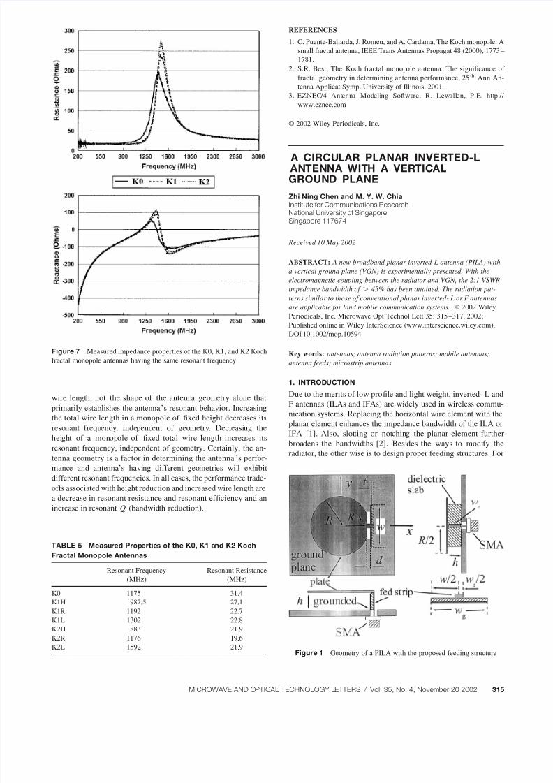
Figure 7 Measured impedance properties of the K0, K1, and K2 Koch
fractal monopole antennas having the same resonant frequency
TABLE 5 Measured Properties of the K0, K1 and K2 Koch
Fractal Monopole Antennas
Resonant Frequency
(MHz)
Resonant Resistance
(MHz)
K0 1175 31.4
K1H 987.5 27.1
K1R 1192 22.7
K1L 1302 22.8
K2H 883 21.9
K2R 1176 19.6
K2L 1592 21.9Figure 1 Geometry of a PILA with the proposed feeding structure
MICROWAVE AND OPTICAL TECHNOLOGY LETTERS / Vol. 35, No. 4, November 20 2002 315
8/8/2019 A Circular Planar Inverted-l
http://slidepdf.com/reader/full/a-circular-planar-inverted-l 2/3
instance, the bandwidths have been significantly increased by
means of the capacitive coupling between the radiator and the
modified feeding probe [3].
In this paper, a new feeding structure is experimentally pre-
sented for enhancing the impedance bandwidth of a PILA. The
planar radiator is put above a ground plane. The proposed feeding
structure consists of a pair of strips separated by a thin vertical
dielectric slab. One of the strips is excited by a coaxial probe at its
bottom and the other one grounded at its bottom and open-cir-
cuited at its top end, which functioning as a vertical ground plane
(VGP). The suspended plate is perpendicular to the VGP and fed
by the probe-driven strip at its edge close to the VGP. The
measurements on input impedance and radiation patterns are car-
ried out.
2. ANTENNA DESIGN
Figure 1 shows the PILA with a segment, which is fed by the
proposed feeding structure. A thin circular copper plate of the
dimensions of R 35 mm was made as a radiator and suspended
parallel to the ground plane at the height of 10 mm. The parameter
s stands for the segment size. The feeding structure comprised a
thin rectangular dielectric slab (Roger4003, r 3.38) of the
dimensions of 10 mm ( h) 50 mm (w) 32 mil(t ). The slab
was vertically amounted to the ground plane and fully grounded at
its bottom. A pair of parallel strips was centrally etched onto the
two surfaces of dielectric slab, respectively. One of the strips of the
width wg w 50 mm was wholly grounded at its bottom and
open-circuited at its top end, which acting as the VGP. A 50
coaxial probe with the diameter of 1.2 mm excited the other strip
of the width ws 2 mm at its bottom through an SMA. The
probe-fed strip fed the plate at the midpoint of the segment through
a horizontal strip measuring 2 mm in width and d 60 mil in
length, where the d indicates the feed gap between the plate edge
and the top end of the VGP. The excited segment was close to andparallel to the VGP top end. In tests, a PEC plate of the dimensions
of 310 330 mm was used to approximate an infinitely ground
plane.
3. MEASURED RESULTS
The measurements on the input impedance and the radiation char-
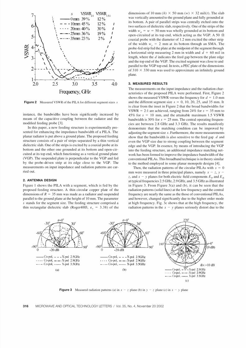
acteristics of the proposed PILA were performed. First, Figure 2
shows the measured VSWR versus the frequency for d 1.0 mm
and the different segment size s 0, 10, 20, 25, and 35 mm. It
is clear from the inset in Figure 2 that the broad bandwidths for
VSWR 2:1 are achieved, ranging from 24% for s 35 mm to
45% for s 10 mm, and the attainable maximum 1.5 VSWR
bandwidth is 30% for s 25 mm. The central operating frequen-
cies are between 2.8 GHz and 3.3 GHz. The results manifestly
demonstrate that the matching condition can be improved by
adjusting the segment size s. Furthermore, the more measurements
show that the bandwidth is also sensitive to the feed gap d and
even the VGP size due to strong coupling between the segment
edge and the VGP. In essence, by means of introducing the VGP
into the feeding structure, an additional impedance matching net-
work has been formed to improve the impedance bandwidth of the
conventional PILAs. This broadband technique is in theory similar
to the method employed in some planar monopole designs [4].
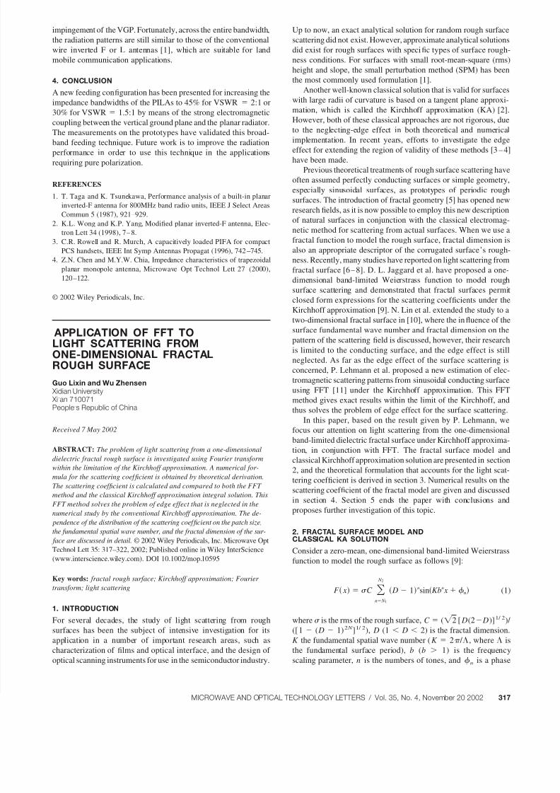
Then, the radiation patterns of the circular PILAs with s 0
mm were measured in three principal planes, namely x z, y
z, and x y planes for both electric field components E and E at typical frequencies 2.5 GHz, 2.9 GHz, and 3.5 GHz as illustrated
in Figure 3. From Figure 3(a) and (b), it can be seen that the
radiation patterns (solid lines) at the low frequency and the central
frequency are nearly the same as the those of conventional PILAs,
and however, changed significantly due to the higher order mode
at high frequency. Fig. 3c shows that at the high frequency, the
radiation patterns in the x y planes seriously distort due to the
Figure 2 Measured VSWR of the PILA for different segment sizes s
Figure 3 Measured radiation patterns (a) in x z plane (b) in y z plane (c) in x y plane
316 MICROWAVE AND OPTICAL TECHNOLOGY LETTERS / Vol. 35, No. 4, November 20 2002
8/8/2019 A Circular Planar Inverted-l
http://slidepdf.com/reader/full/a-circular-planar-inverted-l 3/3
impingement of the VGP. Fortunately, across the entire bandwidth,
the radiation patterns are still similar to those of the conventional
wire inverted F or L antennas [1], which are suitable for land
mobile communication applications.
4. CONCLUSION
A new feeding configuration has been presented for increasing the
impedance bandwidths of the PILAs to 45% for VSWR 2:1 or
30% for VSWR 1.5:1 by means of the strong electromagnetic
coupling between the vertical ground plane and the planar radiator.
The measurements on the prototypes have validated this broad-
band feeding technique. Future work is to improve the radiation
performance in order to use this technique in the applications
requiring pure polarization.
REFERENCES
1. T. Taga and K. Tsunekawa, Performance analysis of a built-in planar
inverted-F antenna for 800MHz band radio units, IEEE J Select Areas
Commun 5 (1987), 921–929.
2. K.L. Wong and K.P. Yang, Modified planar inverted-F antenna, Elec-
tron Lett 34 (1998), 7–8.
3. C.R. Rowell and R. Murch, A capacitively loaded PIFA for compact
PCS handsets, IEEE Int Symp Antennas Propagat (1996), 742–745.
4. Z.N. Chen and M.Y.W. Chia, Impedance characteristics of trapezoidal
planar monopole antenna, Microwave Opt Technol Lett 27 (2000),
120–122.
© 2002 Wiley Periodicals, Inc.
APPLICATION OF FFT TOLIGHT SCATTERING FROMONE-DIMENSIONAL FRACTALROUGH SURFACE
Guo Lixin and Wu Zhensen Xidian University Xi’an 710071People’s Republic of China
Received 7 May 2002
ABSTRACT: The problem of light scattering from a one-dimensional
dielectric fractal rough surface is investigated using Fourier transform
within the limitation of the Kirchhoff approximation. A numerical for-
mula for the scattering coef ficient is obtained by theoretical derivation.
The scattering coef ficient is calculated and compared to both the FFT
method and the classical Kirchhoff approximation integral solution. This
FFT method solves the problem of edge effect that is neglected in the
numerical study by the conventional Kirchhoff approximation. The de-
pendence of the distribution of the scattering coef ficient on the patch size,
the fundamental spatial wave number, and the fractal dimension of the sur-
face are discussed in detail. © 2002 Wiley Periodicals, Inc. Microwave Opt
Technol Lett 35: 317–322, 2002; Published online in Wiley InterScience
(www.interscience.wiley.com). DOI 10.1002/mop.10595
Key words: fractal rough surface; Kirchhoff approximation; Fourier
transform; light scattering
1. INTRODUCTION
For several decades, the study of light scattering from rough
surfaces has been the subject of intensive investigation for its
application in a number of important research areas, such as
characterization of films and optical interface, and the design of
optical scanning instruments for use in the semiconductor industry.
Up to now, an exact analytical solution for random rough surface
scattering did not exist. However, approximate analytical solutions
did exist for rough surfaces with specific types of surface rough-
ness conditions. For surfaces with small root-mean-square (rms)
height and slope, the small perturbation method (SPM) has been
the most commonly used formulation [1].
Another well-known classical solution that is valid for surfaces
with large radii of curvature is based on a tangent plane approxi-
mation, which is called the Kirchhoff approximation (KA) [2].
However, both of these classical approaches are not rigorous, due
to the neglecting-edge effect in both theoretical and numerical
implementation. In recent years, efforts to investigate the edgeeffect for extending the region of validity of these methods [3–4]
have been made.
Previous theoretical treatments of rough surface scattering have
often assumed perfectly conducting surfaces or simple geometry,
especially sinusoidal surfaces, as prototypes of periodic rough
surfaces. The introduction of fractal geometry [5] has opened new
research fields, as it is now possible to employ this new description
of natural surfaces in conjunction with the classical electromag-
netic method for scattering from actual surfaces. When we use a
fractal function to model the rough surface, fractal dimension is
also an appropriate descriptor of the corrugated surface’s rough-
ness. Recently, many studies have reported on light scattering from
fractal surface [6–8]. D. L. Jaggard et al. have proposed a one-
dimensional band-limited Weierstrass function to model roughsurface scattering and demonstrated that fractal surfaces permit
closed form expressions for the scattering coef ficients under the
Kirchhoff approximation [9]. N. Lin et al. extended the study to a
two-dimensional fractal surface in [10], where the influence of the
surface fundamental wave number and fractal dimension on the
pattern of the scattering field is discussed, however, their research
is limited to the conducting surface, and the edge effect is still
neglected. As far as the edge effect of the surface scattering is
concerned, P. Lehmann et al. proposed a new estimation of elec-
tromagnetic scattering patterns from sinusoidal conducting surface
using FFT [11] under the Kirchhoff approximation. This FFT
method gives exact results within the limit of the Kirchhoff, and
thus solves the problem of edge effect for the surface scattering.
In this paper, based on the result given by P. Lehmann, we
focus our attention on light scattering from the one-dimensional
band-limited dielectric fractal surface under Kirchhoff approxima-
tion, in conjunction with FFT. The fractal surface model and
classical Kirchhoff approximation solution are presented in section
2, and the theoretical formulation that accounts for the light scat-
tering coef ficient is derived in section 3. Numerical results on the
scattering coef ficient of the fractal model are given and discussed
in section 4. Section 5 ends the paper with conclusions and
proposes further investigation of this topic.
2. FRACTAL SURFACE MODEL ANDCLASSICAL KA SOLUTION
Consider a zero-mean, one-dimensional band-limited Weierstrass
function to model the rough surface as follows [9]:
F x C n N 1
N 2
D 1nsinKbn x n (1)
where is the rms of the rough surface, C (2 [ D(2 D)]1/ 2)/
([ 1 ( D 1)2 N ]1/ 2), D (1 D 2) is the fractal dimension.
K the fundamental spatial wave number (K 2 / , where is
the fundamental surface period), b (b 1) is the frequency
scaling parameter, n is the numbers of tones, and n is a phase
MICROWAVE AND OPTICAL TECHNOLOGY LETTERS / Vol. 35, No. 4, November 20 2002 317