A co-operative formation-based collision avoidance approach for agroup of autonomous vehicles (Special Issue on Adaptive Control andSignal Processing in Marine System)Yang, A., Naeem, W., Fei, M., & Tu, X. (2017). A co-operative formation-based collision avoidance approach fora group of autonomous vehicles (Special Issue on Adaptive Control and Signal Processing in Marine System).International Journal of Adaptive Control and Signal Processing, 31(4), 489-506.https://doi.org/10.1002/acs.2563
Published in:International Journal of Adaptive Control and Signal Processing
Document Version:Peer reviewed version
Queen's University Belfast - Research Portal:Link to publication record in Queen's University Belfast Research Portal
Take down policyThe Research Portal is Queen's institutional repository that provides access to Queen's research output. Every effort has been made toensure that content in the Research Portal does not infringe any person's rights, or applicable UK laws. If you discover content in theResearch Portal that you believe breaches copyright or violates any law, please contact [email protected].
A co-operative formation-based collision avoidanceapproach for a group of autonomous vehicles
Aolei Yang, Wasif Naeem, Minrui Fei, and Xiaowei Tu
Abstract
This paper employs a unique decentralised cooperative control method to realise a formation-based collisionavoidance strategy for a group of autonomous vehicles. In this approach, the vehicles’ role in the formation and theiralert and danger areas are first defined, and the formation-based intra-group and external collision avoidance methodsare then proposed to translate the collision avoidance problem into the formation stability problem. The extension-decomposition-aggregation formation control method is next employed to stabilise the original and modifiedformations whilst manoeuvring, and subsequently solve their collision avoidance problem indirectly. Simulationstudy verifies the feasibility and effectiveness of the intra-group and external collision avoidance strategy. It isdemonstrated that both formation control and collision avoidance problems can be simultaneously solved if thestability of the expanded formation including external obstacles can be satisfied.
All collisions either at sea, land or in the air have serious environmental, economical, and humanlife implications. The sinking of the Titanic was an infamous catastrophe at sea [1] caused by collisionwith an iceberg. Similar unfortunate events had also occurred in the air such as the 2002 Uberlingenmid-air collision between the Bashkirian Airlines Flight 2937 and the Boeing 757-23APF cargo jetin southern Germany [2]. In cooperative control applications involving multiple vehicles, this problemis further exacerbated as collision within the formation also needs to be considered. The provision ofcollision avoidance capability is thus considered an integral part of any manned or unmanned system. Forsurveillance type missions, an aircraft with such a function can safely fly at low-altitudes to minimisethe possibility of detection by a radar [4], [5]. Similarly, a submarine can swim stealthily close to theseafloor to minimise the risk of detection by sonar equipment [6]. Another growing application of UAVs incivilian domain is the use of quadrotors for photography, hence safety is critical. Here, collision avoidanceis explicitly defined as the capability of a vehicle (individually or within a formation) to detect and avoidcollisions with unidentified objects (UO), while still attempting to accomplish the prescribed mission. Inthe technical sense, collision avoidance strategies are usually software-based whereas onboard sensorsdetect external objects/obstacles and monitor & map the dynamic outdoor environment. Additionally,any evasive strategy should be able to provide sufficient lead time and to guide the vehicle(s) to takeappropriate avoidance action [3] by making use of a decision maker which is employed to evaluate theprobability of collision.
A number of approaches have been proposed to address the collision avoidance problem. These ingeneral fall into three categories: prescribed, optimised, and reactive approaches [8]. Noting that obstacleavoidance is generally associated with path planning, in [9], an A* algorithm was applied to find a pathin the midst of obstacles and conflicts, which is a typical ’prescribed’ approach. Lamiraux et al. in [10]
A. Yang, and M. Fei are with the School of Mechatronic Engineering and Automation, Shanghai University, 200072, Shanghai, P. R.China. W. Naeem is with the School of Electronics, Electrical Engineering and Computer Science, Queen’s University Belfast, BT9 5AH,UK. Corresponding author: Wasif Naeem, Email: [email protected]
2
presented a hybrid method where a path planned for known obstacles is deformed to deal with unknownones. A similar method was also proposed in [11]. For the prescribed collision avoidance approach, allvehicles would follow a set of rules which should be designed or constructed in advance. However, it isnot applicable for use in unknown environments [12].
Conversely, optimised methods involve calculating the best path for all the vehicles to take cooperativeactions to avoid other vehicles or obstacles. It is a look-ahead approach which operates by minimising adefined cost function [13]. Most of the control framework of this strategy is centralised, however thereexists the problem of a single point of failure [14]. The reactive approach includes the likes of potentialfield approach [15]. In this method, the collision avoidance action is to react online to the current stateof the system, rather than planning the path in advance. Attractive and repulsive forces exist betweenvehicles, waypoints/goal and obstacles similar to the reflexive forces between two (same or oppositely)charged particles [16], [17]. Generally speaking, this strategy is decentralised where each individual vehiclecalculates its own collision avoidance action based on surrounding vehicles, goal and obstacles [18].
In addition to the above three typical categories, a number of other novel approaches can be found in theliterature. For instance, job-scheduling technique [19] was employed for intersection collision avoidance(ICA) applications. Furthermore, a collision warning algorithm was proposed to apply to general trafficscenarios [20] and for intersections [21].
A robust collision avoidance approach should be able to deal with both static and dynamic obstaclespresent in the environment. Static obstacles include mountains, buildings, forests etc. whereas dynamicobstacles constitute other intra-group vehicles in the formation and external vehicles (friendly or hostile)that are present in the proximity of the current vehicle. Static obstacles are relatively easier to handle, andare commonly dealt with through global path planning [3]. For dynamic obstacles, the general approachis to estimate the speed and direction of motion using sensor measurements, and subsequently calculatethe obstacle position over time. A simple estimator used in many applications is the Kalman filter andcollision cone concept [22]. Apart from the types of obstacles, other factors such as obstacle shape andsize increase the complexity of the collision avoidance problem. It is normal practice to assume that thevehicles and obstacles are surrounded by safety circles or spheres [23], which determine safe boundariesfor collision avoidance purposes. In [24], such a safety circle was employed for obstacle avoidance withmultiple mobile robots, where two robots cooperated within a specified area, while others waited outsideit.
A. Contribution of this paperIn comparison with the above three strategies, the proposed collision avoidance approach is based
on formation-based control and stability. The underlying concept is that when obstacles or UOs invadethe predefined alert area of the current vehicle, the current vehicle considers these obstacles or UOs asits reaction “vehicles” in order to construct a virtual formation. Having considered all these invadingvehicles/obstacles as nodes in the virtual formation topology, a formation control methodology whichshould be able to guarantee the stability during formation change or transformation can be employed tostabilise the augmented formation system, and simultaneously to implement the so-called formation-basedcollision avoidance.
This method is different from other common approaches, which are generally based on a single strategy,in that it is a hybrid method from the perspective of architecture, containing both the prescribed andreactive strategies. The prescribed one (Level 1) is used to pre-calculate the formation geometries basedon the known mission map and obstacles, and the reactive one (Level 2) is designed to deal with thecollision avoidance problem caused by the presence of UOs. The feasible formation control method isthen employed to maintain the stability of the formation (including the UOs) during formation geometriestransformation. This way, the collision avoidance problem is translated into the formation stability problem.
Specifically, the formation-based intra-group and external collision avoidances and the related algorithmsare separately discussed in detail to determine the formation geometries. In simulations, the extension-
3
decomposition-aggregation formation control method was employed to maintain the stability of the for-mation geometries and to verify the feasibility and effectiveness of the intra-group and external collisionavoidances. Further, based on the formation control and stability, this method can be conveniently extendedto handle the static and dynamic collision avoidance problems together.
This remainder of the paper is organised as follows. Section II presents some necessary backgroundmaterial and preliminaries. The formation-based collision avoidance approach is presented in Section III,which forms the bulk of the paper, including the intra-group and external collision avoidance algorithms.Simulation results are described Section IV and concluding remarks and suggestions for future work arefinally provided in Section V.
II. PRELIMINARIES
During the formation manoeuvre, there inevitably exists the collision risk between vehicles and ob-stacles, and the ability of avoiding collision is also an important feature to assess the effectivenessof the formation manoeuvre, since there may be some factors that incur unexpected intra-group orvehicle collisions, for example, (1) communication between the vehicles within the formation may breaktemporarily or permanently due to natural or technological reasons during manoeuvring; (2) due tounknown/unexpected electromagnetic environmental disturbances, the existence of long transmission time-delay makes an impractical control input (too large amplitude), and subsequently might lead to unpredictedresponse; (3) the decentralised formation controller for each vehicle can be used to avoid collisionsefficiently, but not necessarily guarantee collision avoidance with other vehicles. In addition, there alsoexists the possibility of collision with unidentified objects (UO), and it is required that the individualvehicle should have the ability of detecting obstacles or UO by using on-board sensors and activating itsreflexive obstacle avoidance.
In this paper, the formation control approach is innovatively used to solve the above collision problems,which is different from general approaches based on path planning, and is called as formation-basedcollision avoidance. Before describing this approach, it is necessary to discuss a few related preliminariesin this section, including the roles of different vehicles in the process of collision avoidance, and thedefinitions of alert area and danger area for each vehicle.
A. Role definition of formation vehiclesEach vehicle within a formation is assigned a discrete variable ri to define its role. The set of these role
variables related to a collection of N vehicles is then represented as r= {ri : i = 1,2, · · · ,N}, the value ofwhich depends on the current formation control problem under consideration. It is assumed that the roleof a vehicle can be changed at any time, that can be written as (1) [25],
r′i = r(xi,ri) (1)
where r′i is the new value of the role variable ri which can be written as ri(t) defining the role of the ith
vehicle at time t.Specifically, two kinds of definitions are presented here to facilitate the following discussion of the
collision avoidance approach. The first one is the so-called “reference vehicle (RV)” [26] defined in aformation, and the other is non-RV (NRV). The RV is chosen by consensus between vehicles, to be thereference point of the overall formation shape. Its main tasks are outlined as follows:
1) The RV should have the capability of communicating with the remote base station, maintaining andupdating the current tasks according to operator’s commands.
2) The RV should have the ability of formation management and maintenance, i.e. updating theformation topology (FT) and achieving the future formation geometry (FG), based on the externalchanging environment.
Here, item 1 above is assumed to be satisfied, and item 2 is the focus as it is closely related to the topicof the formation-based collision avoidance.
4
When changing the formation topology, two modes are defined: positive accept mode and active discardmode. The former means that there are many requests from external vehicles to apply for joining the currentformation system, or an internal vehicle may apply for leave the current formation system. The latter meansthat if one vehicle moves away beyond the maximal radio communication range or there is communicationfailure for the vehicle in the formation, this vehicle should be deserted by the current formation systemand the remaining vehicles will rearrange themselves as well as generating a new formation topology.Note that the second mode is referred to as the desertion problem in this paper, and vehicle breakdowncan be considered as a case of the desertion problem. In addition, the capability of calculating the futureformation geometry can be used to support the implementation of collision avoidance. For example, basedon an area map and positions of obstacles which are known a priori, the RV can calculate a sequence offormation geometries to guarantee collision avoidance for the whole group.
The task of NRVs is relatively simple, which is to maintain the formation stability with respect toreference formation commands and changing environment. However, each NRV should have the capabilityof taking over RV’s role, in order to continue the formation manoeuvring mission in case of RV breakdown.This will improve the robustness of formation manoeuvre under uncertain environments, provide the multi-vehicle formation having the capability of rebuilding and self-repairing the formation structure, and finallyincrease mission success rate.
Compared to the above definitions of vehicle’s roles (RV and NRV), the second role definition is basedon the formation topological structure. An illustration of the vehicle’s role definition is shown in Fig. 1,where the whole formation topology can be expressed as (2).
E = {TF2→1,T
F1↔3,T
F2↔3,T
F2↔4,T
F4→3,T
F5→4,T
F5→3} (2)
1
2
3
4
5 F2 3T
F2 1T
F4 3T
F5 4T
F5 3T
F2 4T
F1 3T
sink vehicle
non-reaction vehicle
relay vehicle
relay vehicle
relay vehicle
Fig. 1. Role definition based on the formation topology
Three kinds of roles: sink, relay and non-reaction vehicles are proposed here to describe each vehicle’sfunction in the formation topology. In Fig. 1, the sink vehicle (vehicle 1) is defined to represent the vehiclewhich only receives data from other vehicles or which only reacts to other vehicles actions. The relayvehicle has a “relay” function, which both transmits and receives data from its interconnecting vehicles,such as vehicle 2, 3 and 4. The last type is the non-reaction vehicle which only transmits data, and itdoes not react to any other vehicles in the formation, such as vehicle 5 in Fig. 1. In general, the relayvehicles are vital for a robust formation, whereas the other two roles rarely appear unless for a specialpurpose. For example, a dispensable vehicle is commonly designated as the sink vehicle, and a UO isalways considered as a non-reaction vehicle to make the UO become a part of the formation.
The two definitions above are generally not independent, and important considerations are required asfollows:
1) The sink vehicle cannot be the RV in the formation.2) In order to improve the response speed, the relay vehicle with maximal interconnections to other
vehicles is generally selected as the RV.
5
3) As for the leader-following formation control strategy, the leader of the overall formation is usuallythe non-reaction vehicle.
B. Alert area and overlap areaAs shown in Fig. 2, zones are defined around the ith vehicle, where the inner area surrounded by the
i
Vir
dVir
Danger area
Alert area
Safe area
Fig. 2. Definition of safe, alert and danger areas for the ith vehicle
solid circle is called the danger area, the circle’s radius is rdVi and its superscript “d” denotes danger. The
annular area between the inner circle and the outer dotted circle with radius rVi is termed as the alertarea, whilst the area outside the alert area is designated as the safe area. During normal operation, otherobjects should stay in the safe area of the ith vehicle. When an object enters into the alert area due to anunexpected reason, the vehicle should activate its collision avoidance routine in order to move itself awayfrom the invading object. Any objects should not be permitted to enter into the danger area because ofhigh collision possibility.
Also, within a formation, vehicles located at different positions might have different alert radii, sothere is a possibility of the alert area overlapping. As shown in Fig. 3, the alert areas of the ith, jth and
i
k
j
E
AB
C
D
VirVjr
Vkr
F
Fig. 3. An illustration of overlapped area for the ith, jth and kth vehicles
kth vehicles overlap each another. Specifically, points A, B and C lie in the overlap areas related to twovehicles’ alert areas, and these corresponding areas are then called as 2-fold overlap areas. By the same
6
token, point D can be considered as a point in the 3-fold overlap area, and points E and F are in 1-foldand 0-fold overlap areas, respectively.
III. FORMATION-BASED COLLISION AVOIDANCE
A. Formation-based collision avoidance methodologyThe proposed formation-based collision avoidance can be described briefly as follows: when obstacles
or UOs invade into the predefined alert area of the current vehicle, it considers these obstacles or UOsas its reaction vehicles. In other words, these obstacles will be considered as a part of the whole “virtual”formation topology once there appears the possibility of a collision. Collision avoidance can then beimplemented by tracking a sequence of feasible formation geometries designed to avoid those UOs.
In order to implement this idea, two requirements are to be satisfied:1) A sequence of feasible formation geometries related to known or unknown maps and obstacles
should be calculated by using prescribed and reactive strategies;2) The employed formation control methodology should be able to guarantee the stability of the
constructed virtual formation during any cooperative transformation.Here, the formation-based collision avoidance strategy contains two stages: deliberative pre-computation
of collision avoidance and reflexive or reactive collision avoidance strategy, which is shown in Fig. 4. The
Deliberative pre-computation of collision avoidance
Reflexive collision avoidance strategyLevel 2
Level 1Obtain a sequence of formation shapes offline for future manoeuvre based on known position
of obstacles
Obtain the real-time formation shape based on real-time environment change, such as the
first level is an offline approach, where a sequence of formation geometries or formation shapes can befirst pre-calculated under the assumption that the mission map and position of static obstacles are knowna priori. These achieved formation shapes are then in turn selected as the real-time reference formationsat specific locations. It is noted that Level 1 is different from simple path planing, and the procedure ofdesigning a formation shape is briefly listed below:
1) Calculate waypoints from start point to destination and construct a desired path.2) Based on the positions and sizes of all known obstacles, successively search the achieved path and
determine the relationship between the lateral width (wF ) of the current formation shape and themaximum clearance (wC) between these obstacles.
3) If wF < wC, it is not necessary to change the current formation geometry, whereas if wF ≥ wC, anew formation shape is needed to be calculated, as well as determining a desired position whereformation will be changed.
4) For simplicity, the adopted strategy for designing a desired formation shape is to give priorityto regulating the lateral formation, and to consider the change of the longitudinal formation as asecondary measure which is employed only when the primary measure is not sufficient to guaranteea collision-free path.
In contrast to the deliberative pre-computation of a collision avoidance manoeuvre in Level 1, Level2 is a reflexive strategy which is designed to enhance the robustness to the varying environment and todeal with emergent obstacles. Various functions in Level 2 are given as follows:
1) Avoid intra-group collision, whether a vehicle within a formation is uncontrollable due to itshardware/software breakdown, or a vehicle receiving incorrect/incomplete commands poses a riskto other vehicles in the formation.
7
2) Avoid any external obstacles as there always exists information discrepancy between the knownmap status and the real-time environment.
3) Avoid stationary and mobile/dynamic UOs. Particularly, the mobile obstacles avoidance approachhas potentially wide application prospects.
The central role of Level 2 is to reconstruct and update the formation structure online as well as tochange the formation geometry based on real-time knowledge about the external environment. Its tasksare detailed as follows:
1) Once a local vehicle is confirmed as malfunctioned, discard the vehicle from the original formationor delete the corresponding node in the formation topology.
2) Once an UO invades into the predefined alert area of the ith vehicle, the related vehicle will acceptthe UO as its reaction target. This means that the original formation system is augmented withthe UO and a new formation topology is created. This newly generated formation is termed as anaugmented formation.
3) Determine a sequence of new formation geometries in real time to make the original formationmove away from the newly joined UO as quickly as possible.
4) Change and update the current formation topology to optimise the formation reaction structure, andconsequently improve the dynamic performance during formation change and obstacle avoidance.
The implementation of task 1 above depends on consensuses among the remaining vehicles and thepre-designed formation self-construction protocol. If the formation connectivity remains undisturbed afterremoving the problem vehicle, the corresponding node can be directly deleted from the original topology.Otherwise, the original formation topology has to be reconstructed based on a relevant protocol. Researchon these self-construction protocols is another broad field, which is not the focus of this paper. In addition,task 4 above is related to finding criteria about how to determine a formation topology which has a betterformation change performance than others. It is deemed important to devote a separate paper to discusswhich of the selected formation topologies is better than others by carrying out comparative simulations.
The proposed approach for task 2 and 3 will be discussed in the following for two cases: intra-groupcollision avoidance and external collision avoidance.
B. Intra-group collision avoidanceThe schematic diagram shown in Fig. 5 illustrates the method of determining an appropriate formation
geometry and for modifying the current formation topology for avoiding intra-group collision. Thisscenario is referred to as internal collision avoidance which mostly occurs when an inner vehicle invadesinto the alert area of neighbouring vehicles due to unexpected external disturbances, communication errorsor malfunctioning. It is assumed that each vehicle in the formation is able to detect any invading objectsby using on-board sensors. Once an object has been detected by the ith vehicle within its alert area, itimmediately activates its collision avoidance routine. The ultimate aim is to keep the invading vehicle atthe minimum safe distance marked by the boundary of the alert area in Fig. 2. Note that the danger circleof each vehicle is not shown in Fig. 5 to avoid any confusion.
In Fig. 5 (A), the formation representation (FR, including formation geometry and topology) for agroup of 4 vehicles using bidirectional communications is illustrated, where the diamond symbolises avehicle, and the dotted circles with radii rV 1, rV 2 and rV 3 indicate the alert areas for the 1st , 2nd and 3rd
vehicles respectively. In this case, the 4th vehicle is assumed to be moving into the alert area of the 1st
vehicle, where prL4 denotes the real or actual position in 1-fold overlap area. It must be underlined that
the small circle labelled by pdL4 is the point joining the alert circle and the extended line of the vector−−−−→
pL1prL4, which is also the nearest point from the alert circle to the current position of the 4th vehicle.
The proposed solution is to change the reference formation from the original FRre f to a newly designedor desired FRd
real . The related formation representations are listed in Table I.
8
2
LX
LY
3Lp
2Lp
3Vr
2Vr
3
1Lp
3Vr
1
F1 2T
F2 3T
F3 1T
4
F4 2T
4rLp
24
dLp
14
dLp
F4 1T
LX
LY
3Lp
2Lp
3Vr
2Vr
3
1Lp
3Vr
1
F1 2T
F2 3T
F3 1T
2
4
F4 3T
F4 1T
4dLp
4rLp
LX
LY
3Lp
2Lp
3Vr
2Vr
3
1Lp
3Vr
1
F1 2T
F2 3T
F3 1T
2
4
F4 3T
F4 1T
4dLp
4rLp
(A) (B)
F4 3T
(C)
Fig. 5. Intra-group vehicles collision avoidance
Note that there are no changes to the topology, since there already exists a direct formation reac-tion defined by TF
4↔1. However, the formation geometry has to be changed from {pL1,pL2,pL3,pL4} to{pL1,pL2,pL3,pd
L4}.On the other hand, as shown in Fig. 5 (B), the 4th vehicle invades the alert area (1-fold overlap area)
of the 2nd vehicle which has no direct reaction to the invading vehicle. Owing to the non-existence ofreaction between the 2nd vehicle and 4th vehicle, the original formation topology needs to be augmentedwith TF
4→2, where pdL4 is the desired reference position for the 4th vehicle. The related sequence showing
9
TABLE ISEQUENCE OF FORMATION REPRESENTATION CORRESPONDING TO FIG. 5 (A)
For the third case depicted in Fig. 5 (C), the 4th vehicle enters into the 2-fold overlap alert area of the1st and 2nd vehicles. This scenario can be considered as the resultant of the two cases shown in Fig. 5(A) and Fig. 5 (B). The previously proposed approach is also suitable to deal with the collision avoidanceproblem in this overlapped area. However, it is noted that there exist two candidates (pd1
L4 and pd2L4) of
the desired reference position for the 4th vehicle. A feasible solution to this problem is to calculate thearithmetic mean of pd1
L4 and pd2L4 as the desired reference position. The relevant sequence of formation
representation is thus listed in Table III.
TABLE IIISEQUENCE OF FORMATION REPRESENTATION CORRESPONDING TO FIG. 5 (C)
Finally, once the invading vehicle has moved to the safe area with regards to the formation, the interruptroutine (emergent task) of the collision avoidance is completed, and the formation system will restore toits previous task before the disruption.
The above discussion to the intra-group collision avoidance approach is based on the perspective ofthe global formation representation. Although it is convenient to analyse, it cannot be directly applied tothe decentralised control framework. It is therefore necessary to decompose the previous global formationexpression into a group of local forms or representations, which will be demonstrated in the followingsubsection.
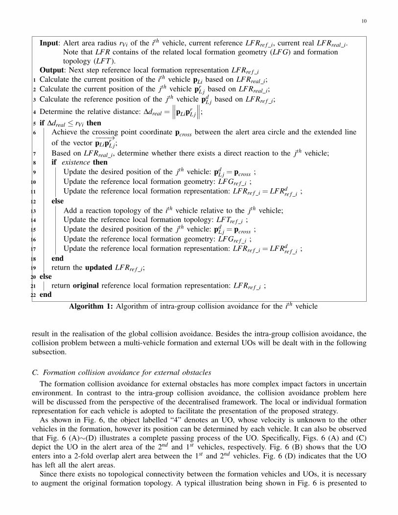
In a decentralised control framework, each vehicle can react or communicate with some of other vehiclesin the formation based on the predefined formation topology. When the jth vehicle invades the alert areaof the ith vehicle, the collision avoidance strategy can be expressed as Algorithm 1, which is the routineexecuted by the ith vehicle during its collision avoidance stage.
It is noted that when the jth vehicle is in a N-fold overlap alert area, this decentralised algorithmremains suitable for all the vehicles. In this scenario, each vehicle, including the invading vehicle, willmake use of Algorithm 1 to avoid collision with other vehicles, and consequently their joint efforts
10
Input: Alert area radius rVi of the ith vehicle, current reference LFRre f i, current real LFRreal i.Note that LFR contains of the related local formation geometry (LFG) and formationtopology (LFT ).
Output: Next step reference local formation representation LFRre f i1 Calculate the current position of the ith vehicle pLi based on LFRreal i;2 Calculate the current position of the jth vehicle pr
L j based on LFRreal i;3 Calculate the reference position of the jth vehicle pd
L j based on LFRre f i;
4 Determine the relative distance: ∆dreal =∥∥∥pLipr
L j
∥∥∥;5 if ∆dreal ≤ rVi then6 Achieve the crossing point coordinate pcross between the alert area circle and the extended line
of the vector−−−→pLipr
L j;7 Based on LFRreal i, determine whether there exists a direct reaction to the jth vehicle;8 if existence then9 Update the desired position of the jth vehicle: pd
L j = pcross ;10 Update the reference local formation geometry: LFGre f i ;11 Update the reference local formation representation: LFRre f i = LFRd
re f i ;12 else13 Add a reaction topology of the ith vehicle relative to the jth vehicle;14 Update the reference local formation topology: LFTre f i ;15 Update the desired position of the jth vehicle: pd
L j = pcross ;16 Update the reference local formation geometry: LFGre f i ;17 Update the reference local formation representation: LFRre f i = LFRd
re f i ;18 end19 return the updated LFRre f i;20 else21 return original reference local formation representation: LFRre f i ;22 end
Algorithm 1: Algorithm of intra-group collision avoidance for the ith vehicle
result in the realisation of the global collision avoidance. Besides the intra-group collision avoidance, thecollision problem between a multi-vehicle formation and external UOs will be dealt with in the followingsubsection.
C. Formation collision avoidance for external obstaclesThe formation collision avoidance for external obstacles has more complex impact factors in uncertain
environment. In contrast to the intra-group collision avoidance, the collision avoidance problem herewill be discussed from the perspective of the decentralised framework. The local or individual formationrepresentation for each vehicle is adopted to facilitate the presentation of the proposed strategy.
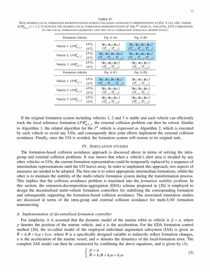
As shown in Fig. 6, the object labelled “4” denotes an UO, whose velocity is unknown to the othervehicles in the formation, however its position can be determined by each vehicle. It can also be observedthat Fig. 6 (A)∼(D) illustrates a complete passing process of the UO. Specifically, Figs. 6 (A) and (C)depict the UO in the alert area of the 2nd and 1st vehicles, respectively. Fig. 6 (B) shows that the UOenters into a 2-fold overlap alert area between the 1st and 2nd vehicles. Fig. 6 (D) indicates that the UOhas left all the alert areas.
Since there exists no topological connectivity between the formation vehicles and UOs, it is necessaryto augment the original formation topology. A typical illustration being shown in Fig. 6 is presented to
11
2LX
LY
3Lp
2Lp
3Vr
2Vr
3
1Lp
3Vr
1
4rLp
4dLpF
1 2T
F2 3T
F3 1T
2
LX
LY
3Lp
2Lp
3Vr
2Vr
3
1Lp
3Vr
1
F1 2T
F2 3T
F3 1T
4
4
F4 2T
F4 2T
4rLp
24
dLp
14
dLp
F4 1T
2LX
LY
3Lp
2Lp
3Vr
2Vr
3
1Lp
3Vr
14
rLp
4dLp
F1 2T
F2 3T
F3 1T
4
F4 1T
(A) (B)
(C)
2LX
LY
3Lp
2Lp
3Vr
2Vr
3
1Lp
3Vr
1
4rLp
F1 2T
F2 3T
F3 1T
4
(D)
Fig. 6. Formation external collision avoidance
explain the strategy. When the UO is in the alert area of the 2nd vehicle as shown in Fig. 6 (A), the 2nd
vehicle needs to augment its original formation topology with an unidirectional topology branch TF4→2,
as well as to change its reference local formation geometry. On the other hand, when the UO invades the2-fold overlap alert area as shown in Fig. 6 (B), the 1st and 2nd vehicles will individually consider theUO as their invader. In other words, each vehicle in the topology is unnecessary to care about whetheror not other vehicles have already considered the UO as their invader. This strategy for avoiding externalcollisions within the 1-fold alert area is also applicable to solve the collision avoidance problem occurringin an N-fold alert area. In Fig. 6, the process of the UO passing through the formation results in a newdesired local formation representation, LFRd
re f i, where the local formation of each vehicle is listed inTable IV.
12
TABLE IVNEW DESIRED LOCAL FORMATION REPRESENTATION DURING COLLISION AVOIDANCE CORRESPONDING TO FIG. 6 (A)∼(D), WHERE
LFRdre f i (i = 1,2,3) DENOTES THE DESIRED LOCAL FORMATION REPRESENTATION OF THE ith VEHICLE, AND LFGi , LFTi CORRESPOND
TO THE LOCAL FORMATION GEOMETRY AND THE LOCAL FORMATION TOPOLOGY, RESPECTIVELY.
Formation vehicles Fig. 6 (A) Fig. 6 (B)
Vehicle 1: LFRdre f 1
LFG1 {pL1,pL2,pL3} {pL1,pL2,pL3,pL4}LFT1 {TF
1↔2,TF1↔3} {TF
1↔2,TF1↔3,T
F4→1}
Vehicle 2: LFRdre f 2
LFG2 {pL1,pL2,pL3,pL4} {pL1,pL2,pL3,pL4}LFT2 {TF
1↔2,TF2↔3,T
F4→2} {TF
1↔2,TF2↔3,T
F4→2}
Vehicle 3: LFRdre f 3
LFG3 {pL1,pL2,pL3} {pL1,pL2,pL3}LFT3 {TF
2↔3,TF1↔3} {TF
2↔3,TF1↔3}
Formation vehicles Fig. 6 (C) Fig. 6 (D)
Vehicle 1: LFRdre f 1
LFG1 {pL1,pL2,pL3,pL4} {pL1,pL2,pL3}LFT1 {TF
1↔2,TF1↔3,T
F4→1} {TF
1↔2,TF1↔3}
Vehicle 2: LFRdre f 2
LFG2 {pL1,pL2,pL3} {pL1,pL2,pL3}LFT2 {TF
1↔2,TF2↔3} {TF
1↔2,TF2↔3}
Vehicle 3: LFRdre f 3
LFG3 {pL1,pL2,pL3} {pL1,pL2,pL3}LFT3 {TF
2↔3,TF1↔3} {TF
2↔3,TF1↔3}
If the original formation system including vehicles 1, 2 and 3 is stable and each vehicle can efficientlytrack the local reference formation LFRd
re f i, the external collision problem can then be solved. Similarto Algorithm 1, the related algorithm for the ith vehicle is expressed as Algorithm 2, which is executedby each vehicle to avoid any UOs, and consequently their joint efforts implement the external collisionavoidance. Finally, once the UO is avoided, the formation system will restore to its original task.
IV. SIMULATION STUDIES
The formation-based collision avoidance approach is discussed above in terms of solving the intra-group and external collision problems. It was shown that when a vehicle’s alert area is invaded by anyother vehicles or UOs, the current formation representation could be temporarily replaced by a sequence ofintermediate representations until the UO leaves away. In order to implement this approach, two aspects ofmeasures are needed to be adopted. The first one is to select appropriate intermediate formations, whilst theother is to maintain the stability of the multi-vehicle formation system during the transformation process.This implies that the collision avoidance problem is translated into the formation stability problem. Inthis section, the extension-decomposition-aggregation (EDA) scheme proposed in [26] is employed todesign the decentralised multi-vehicle formation controllers for stabilising the corresponding formationand subsequently supporting the formation-based collision avoidance. The associated simulation studiesare discussed in terms of the intra-group and external collision avoidance for multi-UAV formationmanoeuvring.
A. Implementation of decentralised formation controllerFor simplicity, it is assumed that the dynamic model of the marine robot or vehicle is p = u, where
p denotes the position of the marine vehicle, and u is the acceleration. For the EDA formation controlmethod [26], the so-called model of the employed individual augmented subsystem (IAS) is given asθ = k1θ + k2u+ k3w, where θ is a specifically designed variable to indirectly reflect formation changes,u is the acceleration of the marine vessel, and w denotes the dynamics of the local-formation error. Thecomplete IAS model can then be constructed by combining the above equations, and is given by (3),{
p = uθ = k1θ + k2u+ k3w (3)
13
Input: Alert area radius rVi of the ith vehicle, current reference LFRre f i, current real LFRreal i.Note that LFR contains of the related local formation geometry (LFG) and formationtopology (LFT ).
Output: Next step reference local formation representation LFRre f i1 Calculate the current position of the ith vehicle pLi based on LFRreal i;2 Calculate the current position of the jth vehicle pr
L j based on LFRreal i;3 Calculate the reference position of the jth vehicle pd
L j based on LFRre f i;
4 Determine the relative distance: ∆dreal =∥∥∥pLipr
L j
∥∥∥;5 if ∆dreal ≤ rVi then6 Achieve the crossing point coordinate pcross between the alert area circle and the extended line
of the vector−−−→pLipr
L j;7 Based on LFRreal i, determine whether there exists a direct reaction to the jth vehicle;8 Add a reaction topology of the ith vehicle relative to the jth vehicle;9 Update the reference local formation topology: LFTre f i ;
10 Update the desired position of the jth vehicle: pdL j = pcross ;
11 Update the reference local formation geometry: LFGre f i ;12 Update the reference local formation representation: LFRre f i = LFRd
re f i ;13 return the updated LFRre f i;14 else15 return original reference local formation representation: LFRre f i ;16 end
Algorithm 2: Algorithm of external collision avoidance for the ith vehicle
The state vector of each IAS is defined as x = [p, p,θ , θ ]T , and (3) can be rewritten as (4).
ddt
ppθ
θ
=
0 1 0 00 0 0 00 0 0 10 0 k1 0
︸ ︷︷ ︸
A
ppθ
θ
+
010k2
︸ ︷︷ ︸
B2
u+
000k3
︸ ︷︷ ︸
B1
w (4)
Based on the achieved formation stability result [26], the controllers for maintaining the stability of theIASs should be designed to stabilise the whole formation which may include the UOs. Here, the exogenousinput w is derived from the formation change or error, and is considered as a bounded disturbance whichneeds to be rejected by the formation control law for stabilising desired formation. The output feedbackH∞ controller [Ak,Bk,Ck,Dk] in (5) is then designed to stabilise the relevant IASs under the boundeddisturbance condition [27]. The purpose is to minimise the exogenous impact, i.e. to maximise the robuststability and performance of the IAS.
˙x = Akx+Bkyu =Ckx+Dky (5)
Here, x denotes the states of controller, which feeds the measurements y back to the control signal u of theplant so that the closed-loop controlled system is internally stable and satisfies the desired performancespecifications.
Note that the above decentralised H∞ controller is sufficient to maintain the formation stability, butit cannot necessarily guarantee zero steady-state formation error, because of system type of the transferfunction from the input u to the target variable θ . Since the variation of θ is a reflection of the formation
14
changing, the problem can be reduced into a standard regulation of the variable θ . The PI-type compensatorD(s) = Kp(1+Ki
/s) is thus employed for eliminating the steady-state formation error.
The parameter values of the IAS system are heuristically chosen as: k1 = 24.5, k2 = −2.5, k3 = 8.3,but can also be related to the dynamics of the marine robot to be controlled. The matrices of the modelin (4) are then given by (6).
A =
0 1 0 00 0 0 00 0 0 10 0 24.525 0
,B1 =
000
8.33
,B2 =
010−2.5
(6)
The Robust Control Toolbox in Matlab can be conveniently used to calculate the relevant output feedbackcontroller matrices. The achieved controller matrices are given in (7).
The parameters of the PI compensator were heuristically chosen as Kp = 10,Ki = 15. The above controllermatrices and parameter values were applied to the following simulation.
B. Formation manoeuvre and collision avoidanceIn dealing with a formation containing multiple vehicles there always exists the possibility of collision
between vehicles within the formation and between vehicles and external UOs. In this section, theformation-based collision avoidance approach presented in Section III will be implemented in a multi-robot formation to evaluate its feasibility and integral performance. In addition, the relationship betweenformation stability and the implementation of the collision avoidance will also be analysed.
Based on the known obstacles map, the DPSS path planning approach [28] was first employed tocalculate the waypoints and subsequently a feasible path from start position to goal position. The multi-robot formation was then tasked to navigate all the waypoints provided in Table V, as well as avoidingcollisions with any UOs.
TABLE VWAYPOINTS OF FORMATION MANOEUVRE TRACKING
x(m) 6 22 45 81 81 56y(m) 6 45 80 80 24 6
Some obstacles were also assumed to be present along the path and hence formation changes wererequired to avoid them. Assuming that the obstacle positions were known a priori, formation changeswere obtained off-line and are shown in Fig. 7, where robot 2 is the reference vehicle (RV) [29] androbots 1 and 3 are its designated neighbours. Specifically, Fig. 7 (A) denotes the reference formationrepresentation, and Fig. 7 (B) and Fig. 7 (C) for the intermediate formation representations. Note that theintermediate formation geometry is only used for avoiding obstacles.
The given map, obstacles and the trajectory of the group of vehicles are displayed in Fig 8 showingsuccessful formation maintenance and formation changes whilst avoiding collisions with obstacles. During
15
3 m
2
1
3
LX
LY
3 m
3 m
2 m
213LX
LY
2 m
2
1
3LX
LY
3 m
3 m
(A) Reference formation
representation
(B) Intermediate formation
representation
(C) Intermediate formation
representation
Fig. 7. Formation representation during multi-robot manoeuvring
Fig. 8. Trajectories of multi-robot formation manoeuvre
the time intervals t = 24s ∼ 36s and t = 80s ∼ 92s, the formation geometry shown in Fig. 7 (B) and(C) were respectively adopted to negotiate forward narrow passages. After successfully navigating thepassages, the group of robots restore to the original formation as shown in Fig. 7 (A).
In addition, the speed and heading dynamics of all the vessels in the formation are shown in Fig. 9,whereas the formation errors for robot 1 and robot 3 relative to robot 2 are displayed in Fig. 10. Thefollowing observations could be made:
1) The formation with 3 marine robots remained stable during all turning manoeuvres and successfully
16
tracked the given waypoints in addition to switching the formations. Hence the proposed formation-based collision avoidance strategy can be used to deal with intra-group as well as and externalcollision problems.
2) Velocity variation with the formation turning or changing could be observed as it was required tomaintain the positions of the robots within the new desired formation as quickly as possible. Allcraft approached the reference speed of 4 knots once the new formation shape was achieved.
3) During the collision avoidance phase between vehicles or between vehicles and obstacles, theproposed evasive algorithm drives the two vehicles away from each other, and prevents entry intotheir respective danger zones.
4) The individual formation errors depicted in Fig. 10 eventually converged to zero after achieving thedesired formation.
0 20 40 60 80 1000
1
2
3
4
Time (s)
Spe
ed (m
/s)
Speed of vehicle 1
0 20 40 60 80 100-3
-2
-1
0
1
2
3
Time (s)
Ang
le (r
ad)
Heading angle of vehicle 1
0 20 40 60 80 1000
1
2
3
4
Time (s)
Spe
ed (m
/s)
Speed of vehicle 2
0 20 40 60 80 100-3
-2
-1
0
1
2
3
Time (s)
Ang
le (r
ad)
Heading angle of vehicle 2
0 20 40 60 80 1000
1
2
3
4
Time (s)
Spe
ed (m
/s)
Speed of vehicle 3
0 20 40 60 80 100-3
-2
-1
0
1
2
3
Time (s)
Ang
le (r
ad)
Heading angle of vehicle 3
Fig. 9. Variation in speeds and orientations
0 20 40 60 80 100-1
0
1
2
3
4
Time (s)
Abs
olut
e va
lue
of e
rror
(m)
Formation error dynamics of Vehicle 1
0 20 40 60 80 100-1
0
1
2
3
4
Time (s)
Abs
olut
e va
lue
of e
rror
(m)
Formation error dynamics of Vehicle 3
Fig. 10. Formation error of robot 1 and robot 3
17
In summary, the proposed formation-based collision avoidance strategy can be conveniently employedto solve the intra-group and external collision problems. The multi-robot formation controller supports notonly the formation manoeuvres, but also the implementation of the formation-based collision avoidance.It can be concluded that having satisfied the stability of the augemented formation (by the addition ofUOs), the problem of collision avoidance can be translated into the formation control problem.
V. CONCLUDING REMARKS
This paper focused on the collision avoidance problem for a group of cooperating vehicles. It isdemonstrated that the traditional formation-based intra-group and external collision avoidance problem,normally solved separately, is translated into a multi-vehicle formation stability problem. The EDAformation control strategy is then adopted to stabilise the corresponding original and new expandedformations. Simulations are performed to verify the feasibility and effectiveness of the intra-group andexternal collision avoidance strategy, and indicate the flexibility and wider applicability in dealing withthe general collision avoidance problem. Future works include the self-construction protocol, formationtopology criteria for collision avoidance, and further application of the formation-based collision avoidanceapproach to other vehicles, i.e. collision avoidance of UAVs formation flight in three dimensions, and solvethe collision avoidance problem in 3-D.
ACKNOWLEDGMENT
This work was supported by the EPSRC under UK-China Science Bridge Grant (EP/G042594/1),Shanghai Municipal Commission Of Economy and Informatization under Shanghai Industry-University-Research Collaboration Grant (CXY-2013-71), the Science and Technology Commission of ShanghaiMunicipality under “Yangfan Program” (14YF1408600), and the National Natural Science Foundation ofChina (Grant No. 61403244).
REFERENCES
[1] “RMS titanic maritime disaster,” last accessed: 09/04/2014.[2] “Uberlingen mid-air collision,” last accessed: 09/04/2014.[3] A. Tsourdos, B. White, and M. Shanmugavel, Cooperative path planning of unmanned aerial vehicles. John Wiley & Sons, 2011.[4] J. Hebert, D. Jacques, M. Novy, and M. Pachter, “Cooperative control of UAVs,” in Proc. the 2001 AIAA Guidance, Navigation and
Control Conference, Montreal, Canada, 2001.[5] M. Zabarankin, S. Uryasev, and P. Pardalos, Optimal risk path algorithms in cooperative control and optimization. Kluwer Academic,
2002.[6] A. R. Washburn, “Continuous autorouters with an application to submarines,” in Research report, NPSOR-91-05, Naval Postgraduate
School, Monterey, USA, 1990.[7] A. D. Zeitlin and M. P. McLaughlin, “Safety of cooperative collision avoidance for unmanned aircraft,” IEEE Aerospace and Electronics
Magazine, pp. 9–13, 2007.[8] J. Kuchar and L. Yang, “A review of conflict detection and resolution modeling methods,” IEEE Transactions on Intelligent
Transportation Systems, vol. 1, no. 4, pp. 179–189, 2000.[9] H. I. Yang and Y. J. Zhao, “Trajectory planning for autonomous aerospace vehicles amid obstacles and conflicts,” Journal of Guidance,
Control and Dynamics, vol. 27, pp. 997–1008, 2004.[10] F. Lamiraux, D. Bonnafous, and O. Lefebvre, “Reactive path deformation for nonholonomic mobile robots,” IEEE Transactions on
Robotics, vol. 20, no. 6, pp. 967–977, 2004.[11] M. Shanmugavel, A. Tsourdos, R. Zbikowski, and B. White, “Path planning of multiple UAVs in an environment of restricted regions,”
in Proc. ASME Int. Mechanical Engineering Congress and Exposition (IMECE2005), Orlando, USA, 2005.[12] L. Pallottino, V. G. Scordio, A. Bicchi, and E. Frazzoli, “Decentralized cooperative policy for conflict resolution in multivehicle
systems,” IEEE Transactions on Robotics, vol. 23, no. 6, pp. 1170–1183, 2007.[13] A. Pongpunwattana and R. Rysdyk, “Real-time planning for multiple autonomous vehicles in dynamic uncertain environments,” Journal
of Aerospace Computing, Information, and Communication, vol. 1, no. 12, pp. 580–604, 2004.[14] S. J. Guy, J. Chhugani, C. Kim, N. Satish, M. Lin, D. Manocha, and P. Dubey, “Highly parallel collision avoidance for multi-agent
simulation,” in Proc. ACM SIGGRAPH Euro-graphics symposium on computer animation, September 3-5 2009, pp. 345–350.[15] J. O. Kim and P. K. Khosla, “Real-time obstacle avoidance using harmonic potential functions,” IEEE Transactions on Robotics and
Automation, vol. 8, pp. 338–349, 1992.[16] S. Wang and H. Schaub, “Spacecraft collision avoidance using coulomb forces with separation distance and rate feedback,” Journal of
Aerospace Computing, Information, and Communication, vol. 31, pp. 740–750, 2008.
18
[17] S. Mastellone, D. M. Stipanovic, C. R. Graunke, K. A. Intlekofer, and M. W. Spong, “Formation control and collision avoidance formulti-agent non-holonomic systems: Theory and experiments,” The International Journal of Robotics Research, vol. 27, no. 1, pp.107–126, 2008.
[18] E. Lalish and K. A. Morgansen, “Distributed reactive collision avoidance,” Autonomous Robots, vol. 32, pp. 207–226, 2012.[19] H. Kowshik, D. Caveney, and P. R. Kumar, “Provable systemwide safety in intelligent intersections,” IEEE Transactions on vehicular
technology, vol. 60, no. 3, pp. 804–818, 2011.[20] M. Braannstroom, E. Coelingh, and J. Sjooberg, “Model-based threat assessment for avoiding arbitrary vehicle collisions,” IEEE
Transactions on intelligent transportation systems, vol. 11, no. 3, pp. 658–669, 2010.[21] D. Greene, J. Liu, J. Reich, Y. Hirokawa, A. Shinagawa, H. Ito, and T. Mikami, “An efficient computational architecture for a collision
early warning system for vehicles, pedestrians, and bicyclists,” IEEE Transactions on intelligent transportation systems, vol. 12, no. 4,pp. 942–953, 2011.
[22] G. Fasano, D. Accardo, and A. Moccia, “Multi-sensor-based fully autonomous non-cooperative collision avoidance system for unmannedair vehicles,” Journal of Aerospace Computing, Information, and Communication, vol. 5, no. 10, pp. 338–360, 2008.
[23] Y. Eun and H. Bang, “Cooperative control of multiple unmanned aerial vehicles using the potential field theory,” Journal of Aircraft,vol. 43, no. 6, pp. 1805–1814, 2006.
[24] A. Fujimori, Y. Ogawa, and P. N. Nikiforuk, “A modification of cooperative collision avoidance for multiple robots using the avoidancecircle,” Proc. of the Institution of Mechanical Engineers, Part I: Journal of Systems and Control Engineering, vol. 216, no. 3, pp.291–299, 2002.
[25] R. M. Murray, “Recent research in cooperative control of multi-vehicle systems,” Journal of Dynamic Systems, Measurement, andControl, vol. 129, no. 5, pp. 571–583, 2007.
[26] A. Yang, W. Naeem, G. W. Irwin, and K. Li, “Stability analysis and implementation of a decentralised formation control strategy forunmanned vehicles,” IEEE Transactions on Control Systems Technology, vol. 22, no. 2, pp. 706–720, 2014.
[27] K. Zhou, J. Doyle, and K. Glover, Robust and optimal control. Prentice Hall, 1996.[28] A. Yang, Q. Niu, W. Zhao, K. Li, and G. W. Irwin, “An efficient algorithm for grid-based robotic path planning based on priority
sorting of direction vectors,” in Proc. international conference on life system modelling and simulation, LSMS 2010, Wuxi, China,2010, pp. 456–466.
[29] A. Yang, W. Naeem, G. W. Irwin, and K. Li, “A decentralised control strategy for formation flight of unmanned aerial vehicles,” inProc. 2012 UKACC International Conference on Control, Cardiff, UK, September 3-5 2012, pp. 345–350.