School of Design and the Built Environment, Curtin University, Bentley, WA 6102, Australia;[email protected]* Correspondence: [email protected]; Tel.: +61-8-9266-4723
Abstract: Previous geo-referencing approaches for building information modeling (BIM) modelscan be problematic due to: (a) the different interpretations of the term ‘geo-referencing’, (b) theinsufficient consideration of the placement hierarchy of the industry foundation classes (IFCs), and (c)the misunderstanding that a common way to embed spatial reference information for IFC is absent.Therefore, the objective of this study is to (1) clarify the meaning of geo-referencing in the context ofBIM/GIS data integration, and (2) develop a common geo-referencing approach for IFC. To achievethe goal, a systematic and thorough investigation into the IFC standard was conducted to assessthe geo-referencing capability of IFC. Based on the investigation, a geo-referencing approach wasestablished using IFC entities that are common in different IFC versions, which makes the proposedapproach common to IFC. Such a geo-referencing approach supports automatic geo-referencing thatwould facilitate the use of BIM models in GIS, e.g., for the construction of digital twins.
Keywords: building information modeling (BIM); geographic information system (GIS); industryfoundation classes (IFC); 3D building model; geo-referencing
1. Introduction
In most of the cases, geographic information systems (GISs) use a coordinate referencesystem (CRS) [1], either geodetic CRS or projected CRS, to integrate heterogeneous spatialdata, i.e., any data that are related to a location [2], such as satellite images, contour data, adigital elevation model (DEM), and other vector or raster data from, e.g., 3D metric survey.The CRS serves as a locating frame in a GIS for heterogeneous spatial datasets that arelinked to different spatial locations. Therefore, datasets to be managed and analyzed in aGIS have to be geo-referenced.
The term geo-referencing is originally from the area of GIS and remote sensing (RS),which refers to the process of assigning geodetic coordinates to pixels of remotely sensedimages, such as satellite images and aerial photo images [3,4]. Before the raw non-geo-referenced spatial datasets can be managed and analyzed in a GIS, their local coordinatesystems (LCSs) have to first be transformed into a proper CRS, which usually consists oftwo steps: (a) establishing the relationship between the raw non-geo-referenced datasetsand a CRS (or establishing spatial reference) through another geo-referenced dataset byselecting ground control points (GCPs) whose coordinates are either known or can beobtained, and (b) obtaining coordinate transformation parameters from these GCPs andtransforming coordinates. This process is referred to as the traditional geo-referencingapproach. The raw non-geo-referenced spatial datasets would be geo-referenced aftercoordinate transformation, and the geo-referenced dataset is only as accurate as the data towhich it is aligned [5]. In order to obtain high geo-referencing accuracy, it is vital to usehigh-resolution and large-scale (fine) datasets.
Building information modeling (BIM) is becoming a promising source of 3D buildingmodels for the geospatial industry [6–10]. Building models created using the BIM techniqueuse local coordinates defined in an LCS. To take full advantages of these building models
ISPRS Int. J. Geo-Inf. 2021, 10, 362. https://doi.org/10.3390/ijgi10060362 https://www.mdpi.com/journal/ijgi
in a GIS, BIM datasets (models) need to be properly geo-referenced [11,12] by establishingspatial reference and transforming coordinates. As with other spatial data, geo-referencedbuilding models can be properly integrated with the surrounding environment in thevirtual 3D world, such as streets, waters, and roads, and can further be used in spatialanalysis or visualization [13,14], such as combined indoor–outdoor route planning [15] andfire response management [16,17]. Geo-referenced building models are also being used bythe architecture, engineering and construction (AEC) domain, for example, in vision-basedstructure inspection [18], laser-scanning-based progress control [19] and point-cloud-basedsemantic building model reconstruction [20].
Essentially, geo-referencing is a process of coordinate transformation that changescoordinates from one system to another [11], and techniques for geo-referencing are maturein GISs [3]. In the context of BIM/GIS data integration, geo-referencing BIM models can,however, be problematic, and it is a major issue in practice according to Arroyo Ohoriet al. [21] and Diakite and Zlatanova [11]. These geo-referencing problems are not fromthe GIS side but mainly from the BIM side in two ways, i.e., the IFC standard itself andmodeling practice. The current practice for geo-referencing BIM models is presented inTable 1.
Table 1. Current viable geo-referencing practice for IFC2x3 and IFC4 model.
IFC2x3 TC1 IFC4
Models with spatialreference
Extending IFC2x3 [22](suggested)
Using IfcMapConversion[22,23]
Models without spatialreference
1. Manually processing [21,24]2. Automatically processing using other geo-referenced data [11]
On one hand, earlier IFC versions before IFC4 do not have an explicit entity for embed-ding spatial reference information and were thought as not sufficient for geo-referencing [25].This problem is solved in IFC4 by introducing a new entity, I f cMapConversion. Based on thisentity, the equation for coordinate transformation has been given by Moult [26]. However,for the IFC2x3 TC1, which is still a valid official IFC standard [27], explicitly embeddingspatial reference information still appears to be a problem. The buildingSMART Aus-tralia [22] suggested extending IFC2x3 TC1 by introducing an extended property set, i.e.,ePSet_MapConversion, which records the same information as I f cMapConversion and en-ables IFC2x3 TC1 models to be geo-referenced as IFC4 models. However, this extension hasnot been officially implemented. It is reasonable to assume that a common geo-referencingapproach would benefit and facilitate the use of BIM models in GIS, as well as researchwork in the AEC domain where geo-referenced BIM models are involved.
On the other hand, due to improper modeling practices, even if the IFC standardis capable of embedding spatial reference information, the required spatial referenceinformation may not be properly assigned during the modeling phase, or not assigned atall, which worsens the geo-referencing problem. BIM models without spatial reference,however, can still be geo-referenced using the traditional geo-referencing approach whichutilizes other datasets (or templates, the term used by Isikdag et al. [28]) that are alreadygeo-referenced, such as the footprint used in studies by Zhu et al. [24] and Diakite et al. [11].The geo-referencing problem caused by improper modeling practice is beyond the scopeof this study, as it is a management problem that can be avoided by standardizing themodeling procedure.
Apart from the above two causes, different interpretations of ‘geo-referencing’ foundin the literature by researchers from areas such as construction and geodesy also aggravatethis problem. Some interpretation has led to different research efforts to address the geo-referencing problem, such as the study by Uggla et al. [29], where geo-referencing wasinterpreted as obtaining geographic coordinates, and the study by Jaud et al. [30], wheregeo-referencing was interpreted as a process of placing an asset on the surface of theEarth. In addition, it is noticed that the Feature Manipulation Engine (FME), the dominant
ISPRS Int. J. Geo-Inf. 2021, 10, 362 3 of 21
commercial tool for BIM/GIS data conversion, has an issue in geo-referencing. All of thesesuggest a knowledge gap in geo-referencing BIM models.
The objective of this study is then to advance geo-referencing theory for BIM and toadvance the application of geo-referencing in BIM/GIS integration by (1) clarifying themeaning of ‘geo-referencing’ in the context of BIM/GIS data integration, (2) investigatingthe geo-referencing capability of the IFC standard, and (3) developing a common geo-referencing approach that suits different IFC versions. The remainder of this paper isorganized as follows. Section 2 compares two different interpretations of geo-referencing,clarifies the meaning of geo-referencing in the context of BIM/GIS data integration, andanalyzes the pros and cons of previous studies on IFC geo-referencing capability. Section 3presents the establishment of the common geo-referencing approach proposed in thisstudy. The validation of the proposed geo-referencing approach is provided in Section 4.Discussions are presented in Section 5, and Section 6 provides the conclusions of this study.
2. Literature Review: Geo-Referencing2.1. Interpretations of ‘Geo-Referencing’
It is noticed that researchers from different backgrounds may have different interpre-tation of ‘geo-reference’. The term ‘geo-referencing’ has been defined in many differentways. This term is originally from GIS and RS [3], which refers to the process of associatinga geospatial dataset (such as a map or a raster image) with geographic or projected CRSthrough a coordinate transformation. Hill [31] expanded the scope of geo-referencingand categorized geo-referencing into informal georeferencing and formal geo-referencing.The former refers to colloquial references to geographical objects such as place name (ap-proximate geo-referencing, beyond the scope of this study), whereas the latter refers toexact location references using coordinate reference systems, which is within the scope ofthis study.
In the category of formal geo-referencing, there exist many definitions for geo-referencing.For example, Sommer and Wade [32] defined geo-referencing as ‘aligning geographicdata to a known coordinate system so it can be viewed, queried, and analyzed withother geographic data’; the United States Geological Survey (USGS) [33] defined geo-referencing as a process to relate the internal coordinate system (or local coordinate system)of a digital map or aerial photo to a ground system of geodetic coordinates (includingmap coordinates [23]), so that basic map analysis can be carried out, such as pointingand clicking on the map to determine the coordinates of a point; according to the OpenGeospatial Consortium (OGC) [34], geo-referencing is geopositioning an object using acorrespondence model derived from a set of points (ground control points) for whichboth ground and image coordinates are known, where a correspondence model means thefunctional (mathematical) relationship between ground and image coordinates; Uggla andHoremuz [29] defined it as a process of ‘assigning geodetic coordinates, i.e., coordinatesrelated to the physical Earth, to geometries’; Jaud et al. [30] defined geo-referencing as a‘process of specifying a geolocation (the placement of an asset on the surface of the Earth)’.
These definitions of geo-referencing appear similar in the purpose, i.e., relating adataset with a coordinate reference system (and eventually with the Earth), but some ofthem actually lead to different research efforts to address the geo-referencing issue, whichis discussed in the next section.
2.2. Geo-Referencing: Establishing Spatial Reference or Coordinate Transformation
The majority of definitions of geo-referencing do not specify the type of CRS, suchas those from Sommer and Wade [32], USGS [33] and OGC [34], and by default, eitherprojected or geographic CRS would work. For clarity, this geo-referencing is referredto as Geo-ref1. In contrast, when investigating the geographic capability of IFC, Ugglaand Horemuz [29] indicated that the coordinates should be exclusively transformed intogeodetic coordinates (longitude, latitude), and the focus was put on coordinate transfor-mation for reducing distortion and improving location accuracy. A similar opinion can
ISPRS Int. J. Geo-Inf. 2021, 10, 362 4 of 21
be found in the study by Jaud et al. [30]. This geo-referencing is referred to as Geo-ref2,and only geographic CRS would work for this type of geo-referencing. The relationshipbetween projected CRS and geographic CRS is that a projected CRS is always created byflattening a geographic CRS using a map projection, i.e., there is always a geographicCRS behind a projected CRS, and the transformation between these two types of CRS hasbeen well addressed by the geospatial industry. In practice, projected CRS is usually usedin applications for small areas, such as mapping, while geographic CRS is usually usedfor global applications, such as positioning. Simply speaking, if a spatial dataset uses aprojected CRS, the underlying geographic CRS indicates the spatial location of the data,and the projected CRS indicates how the data can be drawn on a 2D plane [35].
Figure 1 shows the difference between these two types of geo-referencing, where howthe virtual world in a GIS is linked with the physical earth via the conceptual world (earth)is illustrated. The conceptual world is the abstract world that geodesists conceptualizeto imitate the physical world. In the conceptual world, a reference ellipsoid is used toapproximate the physical earth, and the reference ellipsoid is linked with a geodetic CRSthrough a datum [36]. The geodetic CRS has many subtypes, and the most commonones include the geographic CRS (the underlying coordinate system is ellipsoidal) [37]and the Earth-centered, Earth-fixed (ECEF) CRS (the underlying coordinate system isCartesian) [38]. These two subtypes of geodetic CRS can be transformed to each other. Incases where a more accurate approximation is needed for a specific portion of the Earth,a local ellipsoid can be used [29], and its local geodetic CRS can be transformed into theECEF CRS. These concepts can be implemented in a GIS to provide a locating frame for thevirtual world. Please refer to [37] for a more detailed introduction to CRSs, geodetic CRSs,and other relevant terms.
ISPRS Int. J. Geo-Inf. 2021, 10, 362 4 of 22
them actually lead to different research efforts to address the geo-referencing issue, which is discussed in the next section.
2.2. Geo-Referencing: Establishing Spatial Reference or Coordinate Transformation The majority of definitions of geo-referencing do not specify the type of CRS, such as
those from Sommer and Wade [32], USGS [33] and OGC [34], and by default, either projected or geographic CRS would work. For clarity, this geo-referencing is referred to as Geo-ref1. In contrast, when investigating the geographic capability of IFC, Uggla and Horemuz [29] indicated that the coordinates should be exclusively transformed into geodetic coordinates (longitude, latitude), and the focus was put on coordinate transformation for reducing distortion and improving location accuracy. A similar opinion can be found in the study by Jaud et al. [30]. This geo-referencing is referred to as Geo-ref2, and only geographic CRS would work for this type of geo-referencing. The relationship between projected CRS and geographic CRS is that a projected CRS is always created by flattening a geographic CRS using a map projection, i.e., there is always a geographic CRS behind a projected CRS, and the transformation between these two types of CRS has been well addressed by the geospatial industry. In practice, projected CRS is usually used in applications for small areas, such as mapping, while geographic CRS is usually used for global applications, such as positioning. Simply speaking, if a spatial dataset uses a projected CRS, the underlying geographic CRS indicates the spatial location of the data, and the projected CRS indicates how the data can be drawn on a 2D plane [35].
Figure 1 shows the difference between these two types of geo-referencing, where how the virtual world in a GIS is linked with the physical earth via the conceptual world (earth) is illustrated. The conceptual world is the abstract world that geodesists conceptualize to imitate the physical world. In the conceptual world, a reference ellipsoid is used to approximate the physical earth, and the reference ellipsoid is linked with a geodetic CRS through a datum [36]. The geodetic CRS has many subtypes, and the most common ones include the geographic CRS (the underlying coordinate system is ellipsoidal) [37] and the Earth-centered, Earth-fixed (ECEF) CRS (the underlying coordinate system is Cartesian) [38]. These two subtypes of geodetic CRS can be transformed to each other. In cases where a more accurate approximation is needed for a specific portion of the Earth, a local ellipsoid can be used [29], and its local geodetic CRS can be transformed into the ECEF CRS. These concepts can be implemented in a GIS to provide a locating frame for the virtual world. Please refer to [37] for a more detailed introduction to CRSs, geodetic CRSs, and other relevant terms.
Figure 1. A simplified relationship model for the physical world, conceptual world and virtual world.
Figure 1. A simplified relationship model for the physical world, conceptual world and virtual world.
Geo-ref1 is then the combination of Process (a) and (b) in Figure 1, and Geo-ref2 isthen the virtual link (c). Geo-ref1 puts more weight on establishing spatial reference, asthe coordinate transformation problem has been well addressed, while Geo-ref2 assumesspatial reference has been established and puts more weight on coordinate transformationin an attempt to improve location accuracy for construction activities. For the purpose ofan easier discussion, data after Process (a) with spatial reference but still in its own LCS arereferred to as semi-geo-referenced data, such as IFC models.
Uggla et al. [29] proposed three methods to practically implement Geo-ref2, as shownin Figure 2. The first step of all the three methods is to convert the LCS into an orientedengineering system based on the established spatial reference. In Method 1, the orientedengineering system is first transformed into a well-known projected CRS, which can be
ISPRS Int. J. Geo-Inf. 2021, 10, 362 5 of 21
transformed into the geographic CRS by a process of inverse projection. In Method 2,the oriented engineering system is first transformed into the ECEF system, whose rela-tionship with the geographic CRS has been well established. In Method 3, where a localellipsoid is used, the oriented engineering system is transformed into the local geodeticCRS, which is later transformed into the ECEF system and eventually transformed into thegeographic CRS.
ISPRS Int. J. Geo-Inf. 2021, 10, 362 5 of 22
Geo-ref1 is then the combination of Process (a) and (b) in Figure 1, and Geo-ref2 is then the virtual link (c). Geo-ref1 puts more weight on establishing spatial reference, as the coordinate transformation problem has been well addressed, while Geo-ref2 assumes spatial reference has been established and puts more weight on coordinate transformation in an attempt to improve location accuracy for construction activities. For the purpose of an easier discussion, data after Process (a) with spatial reference but still in its own LCS are referred to as semi-geo-referenced data, such as IFC models.
Uggla et al. [29] proposed three methods to practically implement Geo-ref2, as shown in Figure 2. The first step of all the three methods is to convert the LCS into an oriented engineering system based on the established spatial reference. In Method 1, the oriented engineering system is first transformed into a well-known projected CRS, which can be transformed into the geographic CRS by a process of inverse projection. In Method 2, the oriented engineering system is first transformed into the ECEF system, whose relationship with the geographic CRS has been well established. In Method 3, where a local ellipsoid is used, the oriented engineering system is transformed into the local geodetic CRS, which is later transformed into the ECEF system and eventually transformed into the geographic CRS.
Figure 2. Scope of Geo-ref1 and Geo-ref2.
In spite of the fact that both of these two types of geo-referencing attempt to link geospatial data with a CRS, they are different in starting point, focus, scope and motivation, as shown in Table 2. Geo-ref1 starts with non-geo-referenced raw spatial data, such as satellite images, with a focus to establish spatial reference for the dataset (which is the vital and first step of geo-referencing), and Geo-ref1 can convert the LCS into either projected CRS or geographic CRS, and the motivation of Geo-ref1 is for spatial data management and analysis in the GIS. In contrast, Geo-ref2 starts from the semi-geo-referenced data with a focus to transform coordinates (second step of geo-referencing) into the geographic CRS, and its motivation is to obtain accurate geodetic coordinates, according to Uggla et al. [29], for construction activities. These differences have determined that more complicated methods and more knowledge with geodesy are needed for Geo-ref2, in order to ‘geo-reference’ datasets.
Figure 2. Scope of Geo-ref1 and Geo-ref2.
In spite of the fact that both of these two types of geo-referencing attempt to linkgeospatial data with a CRS, they are different in starting point, focus, scope and motivation,as shown in Table 2. Geo-ref1 starts with non-geo-referenced raw spatial data, such assatellite images, with a focus to establish spatial reference for the dataset (which is the vitaland first step of geo-referencing), and Geo-ref1 can convert the LCS into either projectedCRS or geographic CRS, and the motivation of Geo-ref1 is for spatial data managementand analysis in the GIS. In contrast, Geo-ref2 starts from the semi-geo-referenced data witha focus to transform coordinates (second step of geo-referencing) into the geographic CRS,and its motivation is to obtain accurate geodetic coordinates, according to Uggla et al. [29],for construction activities. These differences have determined that more complicatedmethods and more knowledge with geodesy are needed for Geo-ref2, in order to ‘geo-reference’ datasets.
Table 2. Differences in starting point, focus, scope, and purpose between Geo-ref1 and Geo-ref2.
Geo-Ref1 Geo-Ref2
Starting point Raw spatial data without spatial reference(non-geo-referenced) Data with spatial reference (semi-geo-referenced)
Scope From non-geo-referenced data to geo-referenced data inCRS
From semi-geo-referenced data to geo-referenced data ingeographic CRS
Motivation Spatial data management and analysis in GIS byproviding a common coordinate framework
Obtaining accurate geodetic coordinates for constructionactivities
ISPRS Int. J. Geo-Inf. 2021, 10, 362 6 of 21
Overall, the meaning of geo-referencing in Geo-ref2 (which is primarily for construc-tion activities) is deviated from the original meaning of geo-referencing in a GIS, and inBIM/GIS integration, the meaning of geo-referencing should be Geo-ref1. In the rest of thispaper, if mentioned, geo-referencing refers to Geo-ref1.
2.3. Geo-Referencing Capability of IFCs
As mentioned above, geo-referencing consists of two steps: (1) step 1: establishingspatial reference and (2) step 2: obtaining coordinate transformation parameters andtransforming coordinates [39], where the first step matters the most, as it is the premiseof the second step, while the second step has been well investigated by the geospatialindustry [30]. For the first step of geo-referencing, BIM models are different from traditionalGIS datasets, such as images. For traditional datasets, the spatial reference is establishedby selecting GCPs [3,24]. Such a manual approach also works for BIM models, but BIMmodels have an additional way, i.e., embedding the spatial reference information withinthem [22]. From the established spatial reference, transformation parameters can be derivedfor coordinate transformation. Therefore, the geo-referencing capability of the IFC refers toits capability to accommodate spatial reference information.
IFC4 has a strong geo-referencing capability with a dedicated entity, I f cMapConversion [40].This class contains six attributes, including Eastings (E), Northings (N), OrthogonalHeight (O),XAxisAbscissa (XAA), XAxisOrdinate(XAO), and Scale (S) [41], from which the transfor-mation parameters required by the coordinate transformation can be derived. Coordinatetransformation through I f cMapConversion has been discussed by Uggla et al. [42] and anequation based on these attributes was given by [26] as follows:
[x′ y′ z′
]= [x y z]×
S× cos θ S× sin θ 0−S× sin θ S× cos θ 0
0 0 1
+ [E, N, O], (1)
where θ = atan2(XAO, XAA). However, I f cMapConversion is an entity unique to IFC4.In contrast, the early IFC version was thought not to have a sufficient geo-referencingcapability. According to Clemen and Hendrik [12], the information from IFC2x3, i.e., thegeographic reference point of the site, can only be used for approximate geo-referencing.It can thus be concluded that a common way to embed spatial reference information foraccurate geo-referencing is absent for IFC.
There are many studies involving the geo-referencing of BIM models, but only a fewof them conducted a systematic investigation into the geo-referencing capability of IFC,such as the study by Uggla et al. [29], the study by Clemen and Hendrik [12], and the studyby Arroyo Ohori et al. [21]. The pros and cons of these studies have been listed in Table 3.
Table 3. Pros and cons of studies on investigating IFC geo-referencing capability.
Pros Cons
Arroyo Ohori et al. [21]• Systematically assessed the geo-referencing
capability of IFCs for practical use• Misinterpretation of the IFC geometry structure• Misinterpretation of IFC entities
Clemen and Hendrik [12]
• Systematically assessed the geo-referencingcapability of IFCs using a concept of level ofgeo-referencing (LoGeoRef) ranging fromLoGeoRef10 to LoGeoRef60
• Misinterpretation of the IFC geometry structure• Misuse of IFC entities
Uggla et al. [29]• An attempt to geo-reference large
infrastructure construction project• Misinterpretation of the IFC geometry structure• Misinterpretation of IFC entities
ISPRS Int. J. Geo-Inf. 2021, 10, 362 7 of 21
Arroyo Ohori et al. [21] carried out a systematic investigation into the IFC standard,and some IFC entities that are relevant to geo-referencing have been investigated in de-tail, such as IfcSite, IfcGeometricRepresentationContext. Clemen and Hendrik [12] cameup with the concept of level of geo-referencing (LoGeoRef), which is used to assess thegeo-referencing capability of IFC models, ranging from LoGeoRef10 to LoGeoRef60. LoGe-oRef10 and LoGeoRef20 are for approximate geo-referencing (informal geo-referencing)using IfcPostalAddress and the geographic reference point in IfcSite, while LoGeoRef30and above are for accurate geo-referencing, using entities such as IfcLocalPlacement ofIfcSite for LoGeoRef30, IfcGeometricRepresentationContext for LoGeoRef40, and IfcMap-Conversion for LoGeoRef50. LoGeoRef60, which suggests using ground control points,has not been implemented. Uggla et al. [29] made an attempt to develop methods for geo-referencing a large infrastructure project in IFCs for construction activities; even thoughtheir focus was the second step (coordinate transformation) instead of the vital first step(establishing spatial reference), the geo-referencing capability of the IFC was investigated.Problems with these studies include the misinterpretation of the IFC geometry structure,the misinterpretation of IFC entities, and the misuse of IFC entities.
(1) Misinterpretation of the IFC geometry structure and misinterpretation of IFCentities. The misinterpretation of the IFC geometry structure is the common problemwithin these studies, where the site was considered as the highest geometry containerof the IFC, which in fact should be IfcProject [43]. This misinterpretation has led to themisinterpretation of other IFC entities. For example, the project base point is the referencepoint for the highest geometry container, i.e., IfcProject, but in the study by Arroyo Ohoriet al. [21], it is interpreted as the reference point of the IfcSite (which was mistakenlyconsidered as the highest geometry container), and similarly, the geographic referencepoint of IfcSite was mistakenly interpreted as the origin of the engineering system (orproject-level LCS) [29]. These two cases are illustrated in Figure 3. The consequenceof these two types of misinterpretation can lead to a systematic location error, due toneglecting the relative placement of IfcSite to IfcProject.
ISPRS Int. J. Geo-Inf. 2021, 10, 362 8 of 22
Figure 3. Geo-referencing in previous studies.
(2) Misuse of IFC entities. Some IFC entities were used against their original purpose. In the study by Clemen and Hendrik [12], in order to geo-reference IFC models, (a) the relative placement attribute (indicated by an IfcAxis2Placement3D object) of IfcSite was used to store its relative placement to a CRS (instead of the project-level LCS) in LoGeoRef30, and (b) the WorldCoordinateSystem attribute (indicated by an IfcAxis2Placement3D object) was used to store the relative placement to a CRS in LoGeoRef40. The consequence of misuse of these IFC entities is the generation of large coordinates, which can cause unknown problems to BIM tools [23]. BIM models with such misused entities cannot be used in BIM tools.
The root of these problems is the insufficient consideration of the placement hierarchy in IFCs. When the placement hierarchy is not considered, it is prone to consider the site as the highest geometry container. Additionally, due to the misuse of IFC entities and the misinterpretation of the IFC geometry structure, the geo-referencing approaches proposed by previous studies are just workarounds that can work in certain situations but cannot actually solve the problem in a common way, i.e., a common geo-referencing approach is still in absence. All of the above suggest a knowledge gap in geo-referencing BIM models in the community.
3. Establishment of the Common Geo-Referencing Approach for IFCs 3.1. Key IFC Entities in Geo-Referencing IFC (Geo-Referencing Elements)
Previous studies have incorporated part of the IFC entities that are relevant to geo-referencing, such as IfcSite and IfcGeometricRepresentationContext, but not all of them, nor in a systematic way. For the purpose of developing a common geo-referencing approach, relevant IFC entities have to be correctly interpreted and systematically linked. After a thorough and systematic investigation into the IFC standard, the IFC entities in Figure 4 have been identified to be related to geo-referencing and linked with each other in a systematic way. These entities, as well as their attributes, are referred to as geo-referencing elements in this study.
Figure 4. IFC entities related to geo-referencing.
Figure 3. Geo-referencing in previous studies.
(2) Misuse of IFC entities. Some IFC entities were used against their original purpose.In the study by Clemen and Hendrik [12], in order to geo-reference IFC models, (a) therelative placement attribute (indicated by an IfcAxis2Placement3D object) of IfcSite wasused to store its relative placement to a CRS (instead of the project-level LCS) in LoGeoRef30,and (b) the WorldCoordinateSystem attribute (indicated by an IfcAxis2Placement3D object)was used to store the relative placement to a CRS in LoGeoRef40. The consequence ofmisuse of these IFC entities is the generation of large coordinates, which can cause unknownproblems to BIM tools [23]. BIM models with such misused entities cannot be used inBIM tools.
The root of these problems is the insufficient consideration of the placement hierarchyin IFCs. When the placement hierarchy is not considered, it is prone to consider the siteas the highest geometry container. Additionally, due to the misuse of IFC entities and the
ISPRS Int. J. Geo-Inf. 2021, 10, 362 8 of 21
misinterpretation of the IFC geometry structure, the geo-referencing approaches proposedby previous studies are just workarounds that can work in certain situations but cannotactually solve the problem in a common way, i.e., a common geo-referencing approach isstill in absence. All of the above suggest a knowledge gap in geo-referencing BIM modelsin the community.
3. Establishment of the Common Geo-Referencing Approach for IFCs3.1. Key IFC Entities in Geo-Referencing IFC (Geo-Referencing Elements)
Previous studies have incorporated part of the IFC entities that are relevant to geo-referencing, such as IfcSite and IfcGeometricRepresentationContext, but not all of them, norin a systematic way. For the purpose of developing a common geo-referencing approach,relevant IFC entities have to be correctly interpreted and systematically linked. After athorough and systematic investigation into the IFC standard, the IFC entities in Figure 4have been identified to be related to geo-referencing and linked with each other in asystematic way. These entities, as well as their attributes, are referred to as geo-referencingelements in this study.
ISPRS Int. J. Geo-Inf. 2021, 10, 362 8 of 22
Figure 3. Geo-referencing in previous studies.
(2) Misuse of IFC entities. Some IFC entities were used against their original purpose. In the study by Clemen and Hendrik [12], in order to geo-reference IFC models, (a) the relative placement attribute (indicated by an IfcAxis2Placement3D object) of IfcSite was used to store its relative placement to a CRS (instead of the project-level LCS) in LoGeoRef30, and (b) the WorldCoordinateSystem attribute (indicated by an IfcAxis2Placement3D object) was used to store the relative placement to a CRS in LoGeoRef40. The consequence of misuse of these IFC entities is the generation of large coordinates, which can cause unknown problems to BIM tools [23]. BIM models with such misused entities cannot be used in BIM tools.
The root of these problems is the insufficient consideration of the placement hierarchy in IFCs. When the placement hierarchy is not considered, it is prone to consider the site as the highest geometry container. Additionally, due to the misuse of IFC entities and the misinterpretation of the IFC geometry structure, the geo-referencing approaches proposed by previous studies are just workarounds that can work in certain situations but cannot actually solve the problem in a common way, i.e., a common geo-referencing approach is still in absence. All of the above suggest a knowledge gap in geo-referencing BIM models in the community.
3. Establishment of the Common Geo-Referencing Approach for IFCs 3.1. Key IFC Entities in Geo-Referencing IFC (Geo-Referencing Elements)
Previous studies have incorporated part of the IFC entities that are relevant to geo-referencing, such as IfcSite and IfcGeometricRepresentationContext, but not all of them, nor in a systematic way. For the purpose of developing a common geo-referencing approach, relevant IFC entities have to be correctly interpreted and systematically linked. After a thorough and systematic investigation into the IFC standard, the IFC entities in Figure 4 have been identified to be related to geo-referencing and linked with each other in a systematic way. These entities, as well as their attributes, are referred to as geo-referencing elements in this study.
Figure 4. IFC entities related to geo-referencing. Figure 4. IFC entities related to geo-referencing.
3.1.1. The Placement Hierarchy in IFCs
The IFC adopts a relative placement system (element→storey→building→site→project,see Figure 5), referred to as placement hierarchy, where an object (child) is placed in relationto an upper class (parent) in the placement hierarchy [44,45]. For example, a building isplaced relative to a site. Each object has its own LCS with an origin of (0, 0, 0), and orien-tation of (1, 0, 0), (0, 1, 0) and (0, 0, 1) for the x-axis, y-axis, and z-axis, respectively. Therelative placement between adjacent LCSs is indicated in the IfcLocalPlacment entity, whichhas two attributes, i.e., PlacementRelTo and RelativePlacement. The PlacementRelTo pointsto another IfcLocalPlacment object which is for the parent class. If the PlacementRelTopoints to null, it means that this object is placed in the project-level LCS (world coordi-nate system) [46]. The RelativePlacement points to a IfcAxis2Placement3D object, whichrecords the origin shift (IfcAxis2Placement3D.Location) and orientation of the child LCS(IfcAxis2Placement3D.Axis for z-axis and IfcAxis2Placement3D.RelDirection for x-axis)in the parent LCS. Through IfcAxis2Placement3D, coordinates in the child LCS can betransformed into the parent LCS [44].
ISPRS Int. J. Geo-Inf. 2021, 10, 362 9 of 21
ISPRS Int. J. Geo-Inf. 2021, 10, 362 9 of 22
3.1.1. The Placement Hierarchy in IFCs The IFC adopts a relative placement system
(elementstoreybuildingsiteproject, see Figure 5), referred to as placement hierarchy, where an object (child) is placed in relation to an upper class (parent) in the placement hierarchy [44,45]. For example, a building is placed relative to a site. Each object has its own LCS with an origin of (0, 0, 0), and orientation of (1, 0, 0), (0, 1, 0) and (0, 0, 1) for the x-axis, y-axis, and z-axis, respectively. The relative placement between adjacent LCSs is indicated in the IfcLocalPlacment entity, which has two attributes, i.e., PlacementRelTo and RelativePlacement. The PlacementRelTo points to another IfcLocalPlacment object which is for the parent class. If the PlacementRelTo points to null, it means that this object is placed in the project-level LCS (world coordinate system) [46]. The RelativePlacement points to a IfcAxis2Placement3D object, which records the origin shift (IfcAxis2Placement3D.Location) and orientation of the child LCS (IfcAxis2Placement3D.Axis for z-axis and IfcAxis2Placement3D.RelDirection for x-axis) in the parent LCS. Through IfcAxis2Placement3D, coordinates in the child LCS can be transformed into the parent LCS [44].
Figure 5. The placement hierarchy in IFC.
Please note that the statement in IFCs (both IFC2x3 and IFC4) [43] that the highest level of the spatial structure is assigned to IfcProject is ambiguous, which can be interpreted in two ways, i.e., (a) the IfcProject is the highest level of the spatial structure, and (b) another spatial container, such as IfcSite, is the highest level of the spatial structure and it is eventually assigned to IfcProject. Nevertheless, in either case, IfcProject is undoubtedly the highest container for shape representations (geometry).
3.1.2. Geographic Reference Point in IfcSite and IfcGeometricRepresentationContext in IfcProject
IfcSite is the IFC entity representing a construction site [47], which defines a geographic reference point for the origin of the site-level LCS, (0, 0, 0), using geographic coordinates (longitude, latitude, elevation) in WGS84, as shown in Figure 6a. IfcGeometricRepresentationContext is the most important attribute of IfcProject for geo-referencing [48]. It defines the context that applies to shape representations within a project and includes two attributes that are essential to establishing spatial referencing, i.e., TrueNorth and WorldCoordinateSystem.
Figure 5. The placement hierarchy in IFC.
Please note that the statement in IFCs (both IFC2x3 and IFC4) [43] that the highest levelof the spatial structure is assigned to IfcProject is ambiguous, which can be interpretedin two ways, i.e., (a) the IfcProject is the highest level of the spatial structure, and (b)another spatial container, such as IfcSite, is the highest level of the spatial structure and itis eventually assigned to IfcProject. Nevertheless, in either case, IfcProject is undoubtedlythe highest container for shape representations (geometry).
3.1.2. Geographic Reference Point in IfcSite and IfcGeometricRepresentationContext inIfcProject
IfcSite is the IFC entity representing a construction site [47], which defines a geo-graphic reference point for the origin of the site-level LCS, (0, 0, 0), using geographiccoordinates (longitude, latitude, elevation) in WGS84, as shown in Figure 6a. IfcGeometri-cRepresentationContext is the most important attribute of IfcProject for geo-referencing [48].It defines the context that applies to shape representations within a project and includestwo attributes that are essential to establishing spatial referencing, i.e., TrueNorth andWorldCoordinateSystem.
ISPRS Int. J. Geo-Inf. 2021, 10, 362 10 of 22
Figure 6. (a) The geographic reference point for IfcSite and (b) the true north in IFC project.
(1) TrueNorth. TrueNorth denotes the direction of the geographic north in the underlying project-level LCS (world coordinate system) using a direction vector (a, b), as shown in Figure 6b. If omitted, it means that the positive y-axis of the project-level LCS points to the geographic north.
(2) World coordinate system. The WorldCoordinateSystem establishes the engineering coordinate system (project-level LCS or world coordinate system) for all representation contexts used by the project [48]. The title of this attribute is, however, somewhat misleading. In BIM and other areas such as computer graphics and CAD, the ‘world coordinate system’ is the local coordinate system of the project [40,49], which refers to the coordinate system of the virtual world created by software that may not be linked to the real world. Meanwhile, in GISs, ‘world coordinate system’ is closer to a coordinate reference system that is related to the real world, which literally means the coordinate system of the real world, such as the term ‘world coordinate reference system’ used by [22]. This difference in interpreting the WorldCoordinateSystem has to be noted, as it has caused confusion among practitioners in the area of BIM/GIS integration. For example, Arroyo Ohori et al. [21] misinterpreted this term and claimed that it stores the origin shift of the engineering coordinate system to the real-world coordinate reference system, when their study was based on IFC2x3. The definitions of the WorldCoordinateSystem in IFC2x3 TC1 and IFC4 are presented in Table 4. It can be noticed that the WorldCoordinateSystem can be used to store the offset only in IFC4, and the offset is not relative to a CRS but to the survey point of the project.
Table 4. Definitions of world coordinate system in IFC2x3 TC1 and IFC4 ADD2 TC1.
IFC2x3 TC1 IFC4 ADD2 TC1
World coordinate
system (WCS)
Establishment of the engineering coordinate system (often referred to as the world coordinate system in CAD) for all representation contexts used by the project. Usually set to origin: (0, 0, 0) and x-axis (1, 0, 0), y-axis (0, 1, 0), and z-axis (0, 0, 1).
Establishment of the engineering coordinate system (often referred to as the world coordinate system in CAD) for all representation contexts used by the project. Usually set to origin: (0, 0, 0) and x-axis (1, 0, 0), y-axis (0, 1, 0), and z-axis (0, 0, 1). If 𝐼𝑓𝑐𝑀𝑎𝑝𝐶𝑜𝑛𝑣𝑒𝑟𝑠𝑖𝑜𝑛 is defined, then the WCS is used to define the offset (origin shift) between the zero point of the local engineering coordinate system and the geographic reference point to which the 𝐼𝑓𝑐𝑀𝑎𝑝𝐶𝑜𝑛𝑣𝑒𝑟𝑠𝑖𝑜𝑛 offset relates. In preferred practice, both points (also known as “project base point” and “survey point”) should be coincidental. However, it is possible to offset the geographic reference point from the local zero point.
Figure 6. (a) The geographic reference point for IfcSite and (b) the true north in IFC project.
(1) TrueNorth. TrueNorth denotes the direction of the geographic north in the under-lying project-level LCS (world coordinate system) using a direction vector (a, b), as shownin Figure 6b. If omitted, it means that the positive y-axis of the project-level LCS points tothe geographic north.
(2) World coordinate system. The WorldCoordinateSystem establishes the engineeringcoordinate system (project-level LCS or world coordinate system) for all representation con-texts used by the project [48]. The title of this attribute is, however, somewhat misleading.
ISPRS Int. J. Geo-Inf. 2021, 10, 362 10 of 21
In BIM and other areas such as computer graphics and CAD, the ‘world coordinate system’is the local coordinate system of the project [40,49], which refers to the coordinate system ofthe virtual world created by software that may not be linked to the real world. Meanwhile,in GISs, ‘world coordinate system’ is closer to a coordinate reference system that is relatedto the real world, which literally means the coordinate system of the real world, such as theterm ‘world coordinate reference system’ used by [22]. This difference in interpreting theWorldCoordinateSystem has to be noted, as it has caused confusion among practitionersin the area of BIM/GIS integration. For example, Arroyo Ohori et al. [21] misinterpretedthis term and claimed that it stores the origin shift of the engineering coordinate system tothe real-world coordinate reference system, when their study was based on IFC2x3. Thedefinitions of the WorldCoordinateSystem in IFC2x3 TC1 and IFC4 are presented in Table4. It can be noticed that the WorldCoordinateSystem can be used to store the offset only inIFC4, and the offset is not relative to a CRS but to the survey point of the project.
Table 4. Definitions of world coordinate system in IFC2x3 TC1 and IFC4 ADD2 TC1.
IFC2x3 TC1 IFC4 ADD2 TC1
World coordinate system(WCS)
Establishment of the engineering coordinatesystem (often referred to as the worldcoordinate system in CAD) for allrepresentation contexts used by the project.Usually set to origin: (0, 0, 0) and x-axis (1, 0,0), y-axis (0, 1, 0), and z-axis (0, 0, 1).
Establishment of the engineering coordinate system (often referredto as the world coordinate system in CAD) for all representationcontexts used by the project.Usually set to origin: (0, 0, 0) and x-axis (1, 0, 0), y-axis (0, 1, 0), andz-axis (0, 0, 1). If I f cMapConversion is defined, then the WCS isused to define the offset (origin shift) between the zero point of thelocal engineering coordinate system and the geographic referencepoint to which the I f cMapConversion offset relates.In preferred practice, both points (also known as “project basepoint” and “survey point”) should be coincidental. However, it ispossible to offset the geographic reference point from the local zeropoint.
According to these definitions, it can be concluded that the WorldCoordinateSystem issupplementary to IfcMapConversion and should be considered during geo-referencing onlywhen the survey point is different from the project base point in IFC4, as shown in Figure 7a.When this happens, the offset between them is defined in the WorldCoordinateSystem. Thesituation where these two points coincide is presented in Figure 7b.
ISPRS Int. J. Geo-Inf. 2021, 10, 362 11 of 22
According to these definitions, it can be concluded that the WorldCoordinateSystem is supplementary to IfcMapConversion and should be considered during geo-referencing only when the survey point is different from the project base point in IFC4, as shown in Figure 7a. When this happens, the offset between them is defined in the WorldCoordinateSystem. The situation where these two points coincide is presented in Figure 7b.
Figure 7. (a) The survey point is not coincidental with the project base point, with an offset of (a,b), and (b) the survey point is coincidental with the project base point, with an offset of (0, 0).
3.2. Combining IFC Placement Hierarchy and Geo-Referencing Elements From the fragmented information from IfcSite, IfcGeometricRepresentationContext,
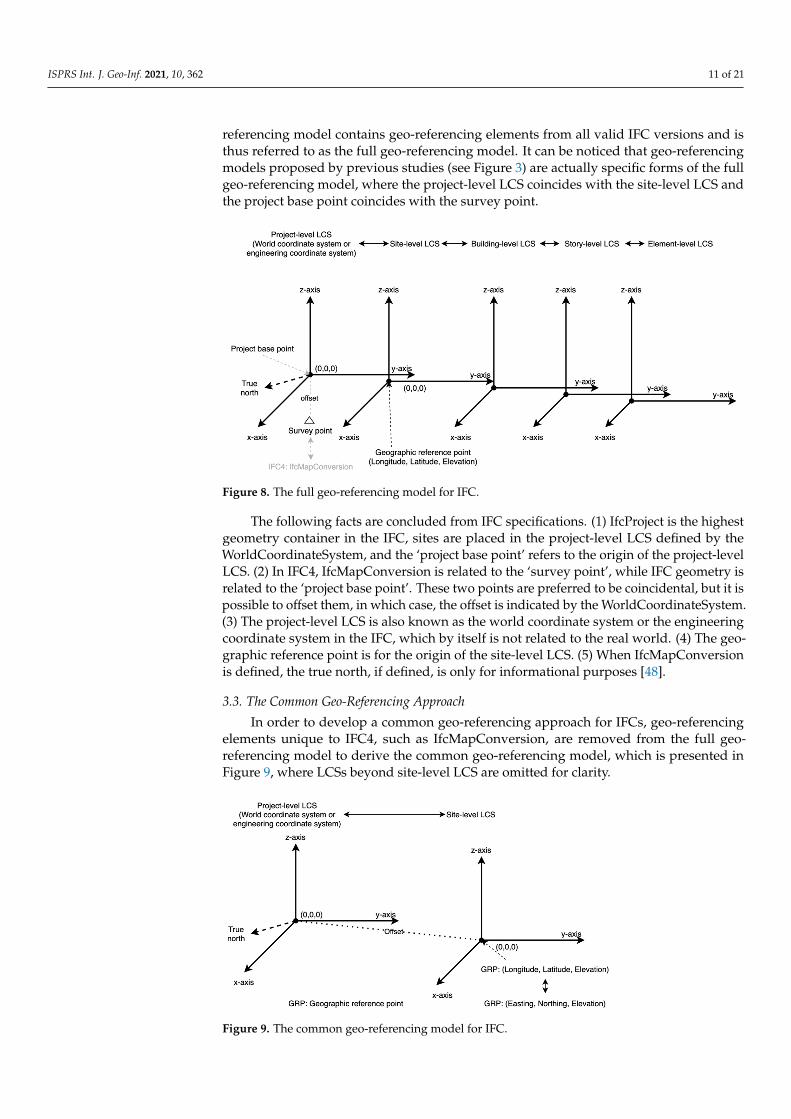
IfcProject, IfcLocalPlacement and IfcSpatialStructureElement in IFCs, the placement hierarchy and geo-referencing elements can be systematically combined to form a structure (see Figure 8), which is referred to as the geo-referencing model in this paper. This geo-referencing model contains geo-referencing elements from all valid IFC versions and is thus referred to as the full geo-referencing model. It can be noticed that geo-referencing models proposed by previous studies (see Figure 3) are actually specific forms of the full geo-referencing model, where the project-level LCS coincides with the site-level LCS and the project base point coincides with the survey point.
Figure 8. The full geo-referencing model for IFC.
The following facts are concluded from IFC specifications. (1) IfcProject is the highest geometry container in the IFC, sites are placed in the project-level LCS defined by the WorldCoordinateSystem, and the ‘project base point’ refers to the origin of the project-level LCS. (2) In IFC4, IfcMapConversion is related to the ‘survey point’, while IFC geometry is related to the ‘project base point’. These two points are preferred to be coincidental, but it is possible to offset them, in which case, the offset is indicated by the
Figure 7. (a) The survey point is not coincidental with the project base point, with an offset of (a,b),and (b) the survey point is coincidental with the project base point, with an offset of (0, 0).
3.2. Combining IFC Placement Hierarchy and Geo-Referencing Elements
From the fragmented information from IfcSite, IfcGeometricRepresentationContext,IfcProject, IfcLocalPlacement and IfcSpatialStructureElement in IFCs, the placement hier-archy and geo-referencing elements can be systematically combined to form a structure(see Figure 8), which is referred to as the geo-referencing model in this paper. This geo-
ISPRS Int. J. Geo-Inf. 2021, 10, 362 11 of 21
referencing model contains geo-referencing elements from all valid IFC versions and isthus referred to as the full geo-referencing model. It can be noticed that geo-referencingmodels proposed by previous studies (see Figure 3) are actually specific forms of the fullgeo-referencing model, where the project-level LCS coincides with the site-level LCS andthe project base point coincides with the survey point.
ISPRS Int. J. Geo-Inf. 2021, 10, 362 11 of 22
According to these definitions, it can be concluded that the WorldCoordinateSystem is supplementary to IfcMapConversion and should be considered during geo-referencing only when the survey point is different from the project base point in IFC4, as shown in Figure 7a. When this happens, the offset between them is defined in the WorldCoordinateSystem. The situation where these two points coincide is presented in Figure 7b.
Figure 7. (a) The survey point is not coincidental with the project base point, with an offset of (a,b), and (b) the survey point is coincidental with the project base point, with an offset of (0, 0).
3.2. Combining IFC Placement Hierarchy and Geo-Referencing Elements From the fragmented information from IfcSite, IfcGeometricRepresentationContext,
IfcProject, IfcLocalPlacement and IfcSpatialStructureElement in IFCs, the placement hierarchy and geo-referencing elements can be systematically combined to form a structure (see Figure 8), which is referred to as the geo-referencing model in this paper. This geo-referencing model contains geo-referencing elements from all valid IFC versions and is thus referred to as the full geo-referencing model. It can be noticed that geo-referencing models proposed by previous studies (see Figure 3) are actually specific forms of the full geo-referencing model, where the project-level LCS coincides with the site-level LCS and the project base point coincides with the survey point.
Figure 8. The full geo-referencing model for IFC.
The following facts are concluded from IFC specifications. (1) IfcProject is the highest geometry container in the IFC, sites are placed in the project-level LCS defined by the WorldCoordinateSystem, and the ‘project base point’ refers to the origin of the project-level LCS. (2) In IFC4, IfcMapConversion is related to the ‘survey point’, while IFC geometry is related to the ‘project base point’. These two points are preferred to be coincidental, but it is possible to offset them, in which case, the offset is indicated by the
Figure 8. The full geo-referencing model for IFC.
The following facts are concluded from IFC specifications. (1) IfcProject is the highestgeometry container in the IFC, sites are placed in the project-level LCS defined by theWorldCoordinateSystem, and the ‘project base point’ refers to the origin of the project-levelLCS. (2) In IFC4, IfcMapConversion is related to the ‘survey point’, while IFC geometry isrelated to the ‘project base point’. These two points are preferred to be coincidental, but it ispossible to offset them, in which case, the offset is indicated by the WorldCoordinateSystem.(3) The project-level LCS is also known as the world coordinate system or the engineeringcoordinate system in the IFC, which by itself is not related to the real world. (4) The geo-graphic reference point is for the origin of the site-level LCS. (5) When IfcMapConversionis defined, the true north, if defined, is only for informational purposes [48].
3.3. The Common Geo-Referencing Approach
In order to develop a common geo-referencing approach for IFCs, geo-referencingelements unique to IFC4, such as IfcMapConversion, are removed from the full geo-referencing model to derive the common geo-referencing model, which is presented inFigure 9, where LCSs beyond site-level LCS are omitted for clarity.
ISPRS Int. J. Geo-Inf. 2021, 10, 362 12 of 22
WorldCoordinateSystem. (3) The project-level LCS is also known as the world coordinate system or the engineering coordinate system in the IFC, which by itself is not related to the real world. (4) The geographic reference point is for the origin of the site-level LCS. (5) When IfcMapConversion is defined, the true north, if defined, is only for informational purposes [48].
3.3. The Common Geo-Referencing Approach In order to develop a common geo-referencing approach for IFCs, geo-referencing
elements unique to IFC4, such as IfcMapConversion, are removed from the full geo-referencing model to derive the common geo-referencing model, which is presented in Figure 9, where LCSs beyond site-level LCS are omitted for clarity.
Figure 9. The common geo-referencing model for IFC.
The key to geo-referencing is to obtain the transformation parameters, i.e., the transformation matrix and the origin shift. From this common geo-referencing model, there are two ways to obtain the transformation parameters, either based on the project-level LCS or the site-level LCS.
When based on the site-level LCS, the transformation parameters can be obtained using the following steps: (a) retrieve reference longitude and latitude from 𝐼𝑓𝑐𝑆𝑖𝑡𝑒, (b) use the latitude and longitude to determine the site location on Earth, and select an appropriate projected CRS for that location, (c) transform latitude and longitude into map coordinates to obtain the origin shift of the site to the selected projected CRS, (d) retrieve the true north direction in the project-level LCS, convert it into the site-level LCS using the relative placement between these two LCSs, and transform it into the transformation matrix, and finally (e) implement coordinate transformation. When based on the project-level LCS, a similar procedure can be followed, but the origin offset derived from the geographic reference point should be transformed into the project-level LCS. These two approaches are equal in performance, and the approach based on site-level LCS is used in this study.
3.3.1. Obtaining Transformation Parameters The transformation matrix and the origin shift can be obtained by using the
relationship between the site-level LCS and the projected CRS, as presented in Figure 10. The solid x-axis and y-axis constitute the site-level LCS, and their intersection is the origin of the site LCS with local coordinates of (0, 0). The solid arrow in the second quadrant of the site LCS points to the true north, (𝑎, 𝑏), or the direction of the N-axis (north) of the underlying projected CRS. Once the N-axis is determined, its E-axis (east), indicated by the dashed arrow in the first quadrant of the site LCS, can be determined as (b, −a), as they are perpendicular to each other and follow the right-hand rule. The origin shift (offset) between the site-level LCS and the projected CRS can be determined by converting the
Figure 9. The common geo-referencing model for IFC.
ISPRS Int. J. Geo-Inf. 2021, 10, 362 12 of 21
The key to geo-referencing is to obtain the transformation parameters, i.e., the trans-formation matrix and the origin shift. From this common geo-referencing model, there aretwo ways to obtain the transformation parameters, either based on the project-level LCS orthe site-level LCS.
When based on the site-level LCS, the transformation parameters can be obtainedusing the following steps: (a) retrieve reference longitude and latitude from I f cSite, (b) usethe latitude and longitude to determine the site location on Earth, and select an appropriateprojected CRS for that location, (c) transform latitude and longitude into map coordinatesto obtain the origin shift of the site to the selected projected CRS, (d) retrieve the truenorth direction in the project-level LCS, convert it into the site-level LCS using the relativeplacement between these two LCSs, and transform it into the transformation matrix, andfinally (e) implement coordinate transformation. When based on the project-level LCS,a similar procedure can be followed, but the origin offset derived from the geographicreference point should be transformed into the project-level LCS. These two approachesare equal in performance, and the approach based on site-level LCS is used in this study.
3.3.1. Obtaining Transformation Parameters
The transformation matrix and the origin shift can be obtained by using the relation-ship between the site-level LCS and the projected CRS, as presented in Figure 10. Thesolid x-axis and y-axis constitute the site-level LCS, and their intersection is the origin ofthe site LCS with local coordinates of (0, 0). The solid arrow in the second quadrant ofthe site LCS points to the true north, (a, b), or the direction of the N-axis (north) of theunderlying projected CRS. Once the N-axis is determined, its E-axis (east), indicated by thedashed arrow in the first quadrant of the site LCS, can be determined as (b, −a), as they areperpendicular to each other and follow the right-hand rule. The origin shift (offset) betweenthe site-level LCS and the projected CRS can be determined by converting the geographiccoordinates, (Long., Lat.) of the geographic reference point into map coordinates (E, N)of the projected CRS, which can be carried out by using PROJ, a software for transforminggeospatial coordinates [50].
ISPRS Int. J. Geo-Inf. 2021, 10, 362 13 of 22
geographic coordinates, (𝐿𝑜𝑛𝑔. , 𝐿𝑎𝑡. ) of the geographic reference point into map coordinates (𝐸, 𝑁) of the projected CRS, which can be carried out by using PROJ, a software for transforming geospatial coordinates [50].
Figure 10. Relationship between the site-level LCS and the projected CRS.
The true north (a, b) can be converted into the transformation matrix using the following steps. (a) Acquiring the direction of three axes of the projected CRS (P1, P2 and P3) in the site-level LCS. In the 3D site-level LCS, the direction of N-axis is P2:(a, b, 0), the direction of E-axis is P1:(b, −a, 0), and the direction of the height axis is P3: (0, 0, 1), while the corresponding direction of these three axes in the projected CRS itself is (0, 1, 0), (1, 0, 0) and (0, 0, 1). (b) Calculating the transformation matrix (M) using the following equation: 𝑃2: 𝑃1: 𝑃3: 𝑏 −𝑎 0𝑎 𝑏 00 0 1 × 𝑀 = 1 0 00 1 00 0 1 , (2)
𝑀 = 𝑏 𝑎 0−𝑎 𝑏 00 0 1 . (3)
The Python codes for retrieving geographic reference point and the true north and converting geographic coordinates into map coordinates are presented in Appendix A.
3.3.2. Coordinate Transformation Coordinate transformation can be implemented using the following equation, once
all the required parameters are in place: [𝑥 𝑦 𝑧 ] = [𝑥 𝑦 𝑧] × 𝑏 𝑎 0−𝑎 𝑏 00 0 1 + [E, N, O], (4)
where [𝑥 𝑦 𝑧 ] is the transformed coordinates, [𝑥 𝑦 𝑧] is the initial coordinates, (𝑎, 𝑏) is derived from the true north, and [E, N, O] represents the origin shift that is derived from latitude, longitude, and elevation of the geographic reference point. The key Python codes for implementing geo-referencing are presented in Appendix B.
4. Experiments, Results and Analysis 4.1. Data
In order to validate the proposed geo-referencing approach, several IFC models were first obtained from IfcWiki [51] and the Open IFC Model Repository (OIMR) [52], as presented in Table 5. After an initial inspection, it was found that only one of them had
Figure 10. Relationship between the site-level LCS and the projected CRS.
ISPRS Int. J. Geo-Inf. 2021, 10, 362 13 of 21
The true north (a, b) can be converted into the transformation matrix using the followingsteps. (a) Acquiring the direction of three axes of the projected CRS (P1, P2 and P3) in thesite-level LCS. In the 3D site-level LCS, the direction of N-axis is P2:(a, b, 0), the directionof E-axis is P1:(b, −a, 0), and the direction of the height axis is P3: (0, 0, 1), while thecorresponding direction of these three axes in the projected CRS itself is (0, 1, 0), (1, 0, 0) and(0, 0, 1). (b) Calculating the transformation matrix (M) using the following equation:
P2 :P1 :P3 :
b −a 0a b 00 0 1
×M =
1 0 00 1 00 0 1
, (2)
M =
b a 0−a b 00 0 1
. (3)
The Python codes for retrieving geographic reference point and the true north andconverting geographic coordinates into map coordinates are presented in Appendix A.
3.3.2. Coordinate Transformation
Coordinate transformation can be implemented using the following equation, once allthe required parameters are in place:
[x′ y′ z′
]= [x y z]×
b a 0−a b 00 0 1
+ [E, N, O], (4)
where [x′ y′ z′] is the transformed coordinates, [x y z] is the initial coordinates, (a, b) isderived from the true north, and [E, N, O] represents the origin shift that is derived fromlatitude, longitude, and elevation of the geographic reference point. The key Python codesfor implementing geo-referencing are presented in Appendix B.
4. Experiments, Results and Analysis4.1. Data
In order to validate the proposed geo-referencing approach, several IFC models werefirst obtained from IfcWiki [51] and the Open IFC Model Repository (OIMR) [52], aspresented in Table 5. After an initial inspection, it was found that only one of them hadembedded the correct spatial reference information (geographic reference point and truenorth). This model quality issue appears to be common and has been encountered by otherstudies [6,21], but this problem is beyond the scope of this study. The model (see Figure 11)with the correct spatial reference, i.e., the Smiley model, was used to validate the proposedmethod, as well as a model with the incorrect spatial reference, i.e., the House 1 model.
ISPRS Int. J. Geo-Inf. 2021, 10, 362 14 of 22
embedded the correct spatial reference information (geographic reference point and true north). This model quality issue appears to be common and has been encountered by other studies [6,21], but this problem is beyond the scope of this study. The model (see Figure 11) with the correct spatial reference, i.e., the Smiley model, was used to validate the proposed method, as well as a model with the incorrect spatial reference, i.e., the House 1 model.
Table 5. Examined IFC models for method validation.
Model Source Geographic Reference Point True North Inspection
Result 1 Institute IfcWiki (8.716667, 49.150000, 0.0) (0, 1) Incorrect
4.2. Implementation For the Smiley model, from its geographic reference point, (8.390980, 49.033244), it
can be determined that this model is located in Germany, where two types of projected CRS are being used, including Gauss–Krueger (zone 2, 3, 4, or 5) and UTM (zone 32 or 33). In this study, WGS84/UTM zone 32N (EPSG: 32632) was selected, as this projected CRS uses the same datum with IFC, i.e., WGS84 [53]. The converted map coordinates for the geographic reference point and the transformation matrix are presented in Table 6.
Table 6. Original spatial reference information and converted transformation parameters.
Original Spatial Reference Transformation Parameters Latitude (degree): 49.033244 Origin shift—Northing (meter): 455484.51059 Longitude (degree): 8.390980 Origin shift—Easting (meter): 5431330.07251
For the Smiley model, from its geographic reference point, (8.390980, 49.033244), itcan be determined that this model is located in Germany, where two types of projectedCRS are being used, including Gauss–Krueger (zone 2, 3, 4, or 5) and UTM (zone 32 or 33).In this study, WGS84/UTM zone 32N (EPSG: 32632) was selected, as this projected CRSuses the same datum with IFC, i.e., WGS84 [53]. The converted map coordinates for thegeographic reference point and the transformation matrix are presented in Table 6.
Table 6. Original spatial reference information and converted transformation parameters.
Original Spatial Reference Transformation Parameters
The quality of geo-georeferencing was assessed via visual inspection with GoogleEarth, and the focus was mainly on the location of the converted models. Google Earthprovides historical images and 3D city models, which ensure that the accuracy of geo-referencing can be assessed for all buildings, including those historical buildings that nolonger exist. The accuracy of elevation is not assessed, out of two reasons: (a) high accuracydigital elevation models (DEMs) required for such assessments are difficult to obtain, and(b) the elevation of models can be easily adjusted in 3D GIS environment. Figure 12 showsthe geo-referenced building model on ArcGIS Online (http://arcg.is/1DTfX0, accessed on20 March 2021), which indicates an accurate geo-referencing.
ISPRS Int. J. Geo-Inf. 2021, 10, 362 15 of 22
Original Spatial Reference Transformation Parameters
The quality of geo-georeferencing was assessed via visual inspection with Google Earth, and the focus was mainly on the location of the converted models. Google Earth provides historical images and 3D city models, which ensure that the accuracy of geo-referencing can be assessed for all buildings, including those historical buildings that no longer exist. The accuracy of elevation is not assessed, out of two reasons: (a) high accuracy digital elevation models (DEMs) required for such assessments are difficult to obtain, and (b) the elevation of models can be easily adjusted in 3D GIS environment. Figure 12 shows the geo-referenced building model on ArcGIS Online (http://arcg.is/1DTfX0, accessed on 20 March 2021), which indicates an accurate geo-referencing.
Figure 12. (a) Geo-referenced models on ArcGIS Online, and (b) building model on Google Earth.
Considering that the purpose of validation is to make sure that the proposed method can place BIM models at the designated locations (i.e., the location defined by the geographic reference point in IfcSite) and orientations, models with an incorrect spatial reference can also be used to validate the method. The proposed method can be claimed as valid if it can place models with an incorrect spatial reference at the designated wrong locations. The House 1 model listed in Table 5 was used for this purpose. The House 1 model has a GRP of (8.436539, 49.100435) and true north of (0.76604, 0.64279). The true north value indicates an angle of 50.0 degree between the y-axis and the true north. Figure 13 presents the processed House 1 model, where only walls are displayed for a clear illustration. Figure 13 proves that the proposed method has performed as expected and can place the model at the designated wrong location, and the orientation of the model is correct, with an angle of 50.0 degree between the y-axis and the true north.
Figure 12. (a) Geo-referenced models on ArcGIS Online, and (b) building model on Google Earth.
Considering that the purpose of validation is to make sure that the proposed methodcan place BIM models at the designated locations (i.e., the location defined by the ge-ographic reference point in IfcSite) and orientations, models with an incorrect spatialreference can also be used to validate the method. The proposed method can be claimedas valid if it can place models with an incorrect spatial reference at the designated wronglocations. The House 1 model listed in Table 5 was used for this purpose. The House1 model has a GRP of (8.436539, 49.100435) and true north of (0.76604, 0.64279). Thetrue north value indicates an angle of 50.0 degree between the y-axis and the true north.Figure 13 presents the processed House 1 model, where only walls are displayed for a clearillustration. Figure 13 proves that the proposed method has performed as expected andcan place the model at the designated wrong location, and the orientation of the model iscorrect, with an angle of 50.0 degree between the y-axis and the true north.
ISPRS Int. J. Geo-Inf. 2021, 10, 362 15 of 22
Original Spatial Reference Transformation Parameters
The quality of geo-georeferencing was assessed via visual inspection with Google Earth, and the focus was mainly on the location of the converted models. Google Earth provides historical images and 3D city models, which ensure that the accuracy of geo-referencing can be assessed for all buildings, including those historical buildings that no longer exist. The accuracy of elevation is not assessed, out of two reasons: (a) high accuracy digital elevation models (DEMs) required for such assessments are difficult to obtain, and (b) the elevation of models can be easily adjusted in 3D GIS environment. Figure 12 shows the geo-referenced building model on ArcGIS Online (http://arcg.is/1DTfX0, accessed on 20 March 2021), which indicates an accurate geo-referencing.
Figure 12. (a) Geo-referenced models on ArcGIS Online, and (b) building model on Google Earth.
Considering that the purpose of validation is to make sure that the proposed method can place BIM models at the designated locations (i.e., the location defined by the geographic reference point in IfcSite) and orientations, models with an incorrect spatial reference can also be used to validate the method. The proposed method can be claimed as valid if it can place models with an incorrect spatial reference at the designated wrong locations. The House 1 model listed in Table 5 was used for this purpose. The House 1 model has a GRP of (8.436539, 49.100435) and true north of (0.76604, 0.64279). The true north value indicates an angle of 50.0 degree between the y-axis and the true north. Figure 13 presents the processed House 1 model, where only walls are displayed for a clear illustration. Figure 13 proves that the proposed method has performed as expected and can place the model at the designated wrong location, and the orientation of the model is correct, with an angle of 50.0 degree between the y-axis and the true north.
Figure 13. The House 1 model processed using the proposed method. With initial incorrect spatial reference, this modelwas placed, as expected, at wrong location with correct orientation.
4.3. Comparison with FME
Figure 14 presents the models geo-referenced using the proposed approach and theFME. It can be noticed that (a) the FME can identify some geo-referencing element in the IFCand use that to convert the LCS into a customized projected CRS titled ‘IFC_COORDSYS_0’,which uses azimuthal equidistant projection with a central meridian of 8.39098 and alatitude of origin of 49.0332445, which corresponds to the geographic reference point, (b)the model from FME is not correctly geo-referenced (with wrong orientation).
ISPRS Int. J. Geo-Inf. 2021, 10, 362 16 of 22
Figure 13. The House 1 model processed using the proposed method. With initial incorrect spatial reference, this model was placed, as expected, at wrong location with correct orientation.
4.3. Comparison with FME
Figure 14 presents the models geo-referenced using the proposed approach and the FME. It can be noticed that (a) the FME can identify some geo-referencing element in the IFC and use that to convert the LCS into a customized projected CRS titled ‘IFC_COORDSYS_0’, which uses azimuthal equidistant projection with a central meridian of 8.39098 and a latitude of origin of 49.0332445, which corresponds to the geographic reference point, (b) the model from FME is not correctly geo-referenced (with wrong orientation).
Figure 14. Models geo-referenced using OCCT-OSA and DIA/FME.
By a closer examination of the model generated by the FME, it can be inferred that the FME does not take the true north and the elevation into consideration during data conversion, from the following facts: (1) the angle between these two models is 147.5, which corresponds to the true north direction (−0.53730, −0.84339) recorded in Table 6, and (2) in order to display these two models at the same elevation, the height offset for the Smiley model is set at 6.5 m, while that for the Smiley_FME model is 116.5 m, which corresponds to the elevation of 110.0 m recorded in Table 6. It can be concluded that the FME is ineffective in geo-referencing IFC models. The failure of the FME, to some extent, reflects the knowledge gap in geo-referencing BIM models in the industry.
5. Discussion In order to address the problems of different interpretations of geo-referencing,
insufficient consideration of the IFC placement hierarchy and misuse of IFC entities in previous studies, this paper clarified the meaning of geo-referencing needed in BIM/GIS integration and provided a common geo-referencing approach for IFC models. The original contribution of this study is at the following levels. (1) Meaning of geo-referencing in BIM/GIS integration
In the area of GIS, the meaning of geo-referencing is clear, which is to link a raw dataset to a CRS for data management and analysis in a GIS (Geo-ref1) [33], and the vital step is to establish spatial reference for the raw dataset. In contrast, another interpretation of geo-referencing tries to link a semi-geo-referenced dataset to a geographic CRS for construction activities (Geo-ref2). By comparing these two types of geo-referencing in terms of starting point, focus, scope and motivation, it is suggested in this study that the geo-referencing needed by BIM/GIS data integration is Geo-ref1.
Figure 14. Models geo-referenced using OCCT-OSA and DIA/FME.
ISPRS Int. J. Geo-Inf. 2021, 10, 362 16 of 21
By a closer examination of the model generated by the FME, it can be inferred thatthe FME does not take the true north and the elevation into consideration during dataconversion, from the following facts: (1) the angle between these two models is 147.5,which corresponds to the true north direction (−0.53730, −0.84339) recorded in Table 6,and (2) in order to display these two models at the same elevation, the height offset forthe Smiley model is set at 6.5 m, while that for the Smiley_FME model is 116.5 m, whichcorresponds to the elevation of 110.0 m recorded in Table 6. It can be concluded that theFME is ineffective in geo-referencing IFC models. The failure of the FME, to some extent,reflects the knowledge gap in geo-referencing BIM models in the industry.
5. Discussion
In order to address the problems of different interpretations of geo-referencing, insuf-ficient consideration of the IFC placement hierarchy and misuse of IFC entities in previousstudies, this paper clarified the meaning of geo-referencing needed in BIM/GIS integra-tion and provided a common geo-referencing approach for IFC models. The originalcontribution of this study is at the following levels.
(1) Meaning of geo-referencing in BIM/GIS integration
In the area of GIS, the meaning of geo-referencing is clear, which is to link a rawdataset to a CRS for data management and analysis in a GIS (Geo-ref1) [33], and the vitalstep is to establish spatial reference for the raw dataset. In contrast, another interpretationof geo-referencing tries to link a semi-geo-referenced dataset to a geographic CRS forconstruction activities (Geo-ref2). By comparing these two types of geo-referencing interms of starting point, focus, scope and motivation, it is suggested in this study that thegeo-referencing needed by BIM/GIS data integration is Geo-ref1.
(2) A full geo-referencing model
The geo-referencing approaches suggested by previous studies are workaroundsthat do not actually solve the problem in a common way, because they failed to considerthe placement hierarchy in the IFC, misinterpreted some geo-referencing elements, andconsidered the site as the highest geometry container of the IFC [12,21,29]. This studysolved these problems by a systematic investigation into the IFC standard and taking theplacement hierarchy into consideration. Based on these, a full geo-referencing model wasdeveloped by incorporating geo-referencing elements in two valid IFC versions. This fullgeo-referencing model can benefit the AEC domain where geo-referenced BIM models areused to facilitate construction activities, such as progress control and structure inspection,by clarifying the geometry structure of IFC.
(3) A common geo-referencing approach
The full geo-referencing model was simplified to be the common geo-referencingmodel, and a common geo-referencing approach was developed, referred to as IFC-Ghere. The proposed IFC-G and the geo-referencing approach for IFC4 (IFC4-G) usingI f cMapConversion are presented in Figure 15a,b, respectively.
These two geo-referencing approaches are mainly different in three aspects: how theorientation of the projected CRS is indicated, how the origin shift is recorded, and how theprojected CRS is defined. (a) IFC-G specifies the orientation of the projected CRS using the N-axis indicated by the true north, which is retrieved from I f cGeometricRepresentationContext,whereas IFC4-G uses the E-axis indicated by (XAA, XAO) retrieved from I f cMapConversion.(b) In terms of origin shift, IFC-G uses (Long., Lat.) from I f cSite, which is transformedinto (E, N), and IFC4-G directly uses (E, N) from I f cMapConversion. (c) In IFC-G, theprojected CRS is defined by users based on the location of the site, whereas in IFC4-G, theprojected CRS is specified by modelers.
ISPRS Int. J. Geo-Inf. 2021, 10, 362 17 of 21
ISPRS Int. J. Geo-Inf. 2021, 10, 362 17 of 22
(2) A full geo-referencing model The geo-referencing approaches suggested by previous studies are workarounds that
do not actually solve the problem in a common way, because they failed to consider the placement hierarchy in the IFC, misinterpreted some geo-referencing elements, and considered the site as the highest geometry container of the IFC [12,21,29]. This study solved these problems by a systematic investigation into the IFC standard and taking the placement hierarchy into consideration. Based on these, a full geo-referencing model was developed by incorporating geo-referencing elements in two valid IFC versions. This full geo-referencing model can benefit the AEC domain where geo-referenced BIM models are used to facilitate construction activities, such as progress control and structure inspection, by clarifying the geometry structure of IFC. (3) A common geo-referencing approach
The full geo-referencing model was simplified to be the common geo-referencing model, and a common geo-referencing approach was developed, referred to as IFC-G here. The proposed IFC-G and the geo-referencing approach for IFC4 (IFC4-G) using 𝐼𝑓𝑐𝑀𝑎𝑝𝐶𝑜𝑛𝑣𝑒𝑟𝑠𝑖𝑜𝑛 are presented in Figure 15a,b, respectively.
Figure 15. (a) General IFC geo-referencing and (b) IFC4 geo-referencing.
These two geo-referencing approaches are mainly different in three aspects: how the orientation of the projected CRS is indicated, how the origin shift is recorded, and how the projected CRS is defined. (a) IFC-G specifies the orientation of the projected CRS using the N-axis indicated by the true north, which is retrieved from 𝐼𝑓𝑐𝐺𝑒𝑜𝑚𝑒𝑡𝑟𝑖𝑐𝑅𝑒𝑝𝑟𝑒𝑠𝑒𝑛𝑡𝑎𝑡𝑖𝑜𝑛𝐶𝑜𝑛𝑡𝑒𝑥𝑡 , whereas IFC4-G uses the E-axis indicated by (𝑋𝐴𝐴, 𝑋𝐴𝑂) retrieved from 𝐼𝑓𝑐𝑀𝑎𝑝𝐶𝑜𝑛𝑣𝑒𝑟𝑠𝑖𝑜𝑛. (b) In terms of origin shift, IFC-G uses (𝐿𝑜𝑛𝑔. , 𝐿𝑎𝑡. ) from 𝐼𝑓𝑐𝑆𝑖𝑡𝑒, which is transformed into (𝐸, 𝑁), and IFC4-G directly uses (𝐸, 𝑁) from 𝐼𝑓𝑐𝑀𝑎𝑝𝐶𝑜𝑛𝑣𝑒𝑟𝑠𝑖𝑜𝑛. (c) In IFC-G, the projected CRS is defined by users based on the location of the site, whereas in IFC4-G, the projected CRS is specified by modelers.
Despite these differences, both of these two geo-referencing approaches can derive the same transformation parameters to achieve same geo-referencing accuracy. Additionally, since the required geo-referencing elements for IFC-G are stable in IFCs, i.e., they have been there in IFCs since as early as IFC2x (which was published in 2000), IFC-G not only can be applied to current two valid IFC versions but also potentially future IFC versions, which makes the proposed approach a common geo-referencing approach for IFCs. In addition, such an approach supports automatic geo-referencing that would facilitate the use of BIM models in GISs, e.g., the construction of city models that contain a large number of building models. (4) Levels of spatial reference
Figure 15. (a) General IFC geo-referencing and (b) IFC4 geo-referencing.
Despite these differences, both of these two geo-referencing approaches can derive thesame transformation parameters to achieve same geo-referencing accuracy. Additionally,since the required geo-referencing elements for IFC-G are stable in IFCs, i.e., they havebeen there in IFCs since as early as IFC2x (which was published in 2000), IFC-G not onlycan be applied to current two valid IFC versions but also potentially future IFC versions,which makes the proposed approach a common geo-referencing approach for IFCs. Inaddition, such an approach supports automatic geo-referencing that would facilitate theuse of BIM models in GISs, e.g., the construction of city models that contain a large numberof building models.
(4) Levels of spatial reference
Both IFC-G and IFC4-G can be used to accurately geo-reference IFC models, but theyactually pose different requirements on BIM modelers and BIM/GIS integration practition-ers. IFC-G makes it easier for BIM modelers to embed spatial reference information in IFCs,as the required geographic reference point and true north are easy to obtain and commonto different IFC versions, considering that defining IfcMapConversion is a complicatedprocess specific for IFC4 [22]. In contrast, IFC4-G makes it easier for BIM/GIS integrationpractitioners to transform coordinates, as all transformation parameters are ready-to-use.According to this, this study defines two levels of spatial reference (LoSR) in IFCs, i.e.,LoSR1: defining the geographic reference point and true north for IFC models and LoSR2:defining IfcMapConversion. During modeling, it is suggested that BIM models shouldembed spatial reference information at least in LoSR1 for the future implementation ofaccurate georeferencing.
6. Conclusions
This study aims to clarify the meaning of geo-referencing in the context of BIM/GISintegration and develop a common approach for geo-referencing IFC models. The mainfindings and outcomes of this study are as follows.
(1) The meaning of geo-referencing has been clarified for BIM/GIS data integration. Geo-referencing in the context of BIM/GIS integration refers to the process of establishingspatial reference for BIM models so that they can be managed and analyzed in a GISafter their local coordinate system is transformed into a proper coordinate referencesystem. Its focus is to establish a spatial reference with a CRS for BIM models,given that the CRS has been properly selected. As for the distortion of the CRS, it isconsidered as acceptable and beyond the scope of geo-referencing in the context ofBIM/GIS integration.
(2) A common geo-referencing approach that can be applied to both officially valid IFCversions, or even future IFC versions, was developed by a systematic and thorough
ISPRS Int. J. Geo-Inf. 2021, 10, 362 18 of 21
investigation into IFC standards and combining the common geo-referencing elementswith the placement hierarchy of IFC. This study proves that the early version of theIFC is already sufficient for accurate geo-referencing. In addition, this study uses allIFC entities in their original way without the need of modification or extension toexisting IFC standards.
(3) A level of spatial reference (LoSR) concept was conceptualized. BIM models at LoSR1should embed information regarding the geographic reference point and true north,while models at LoSR2 should define IfcMapConversion. It is suggested that BIMmodels should be at least in LoSR1 in order to be accurately geo-referenced.
This common geo-referencing approach can facilitate BIM/GIS data integration andin a broad sense benefit studies that use BIM and GISs to solve engineering problems inthe AEC domain, such as the aforementioned fire emergency response and indoor–outdoornavigation. In addition, this study can facilitate the development of smart cities anddigital twins, where an automatic and efficient method is needed to geo-reference a largenumber of building models, in order to integrate various spatial data for visualization ordecision making.
This paper addressed the problem of geo-referencing building models in IFCs, whichare relatively small structures compared with infrastructures, such as road. While theIFC starts to cover the infrastructure domain, a proper geo-referencing approach is alsoneeded for these structures, which should be investigated in the future. Another concernfor geo-referencing BIM models is the quality of BIM models. As revealed during theexperiment, among these IFC models obtained online, only one of them embeds correctspatial reference information. This indicates that embedding spatial reference informationin BIM models has not been given sufficient attention, which should be addressed tofacilitate the use of BIM models in the geospatial industry and in the AEC domain.
Author Contributions: Conceptualization, Junxiang Zhu and Peng Wu; methodology, Junxiang Zhu;software, Junxiang Zhu; validation, Junxiang Zhu; writing—original draft preparation, JunxiangZhu; writing—review and editing, Junxiang Zhu and Peng Wu; funding acquisition, Peng Wu. Allauthors have read and agreed to the published version of the manuscript.
Funding: This research was funded by the Australian Research Council, grant number DP180104026.
Data Availability Statement: Data available in a publicly accessible repository that does not issueDOIs. Publicly available datasets were analyzed in this study. This data can be found here:https://www.ifcwiki.org/index.php?title=IFC_Wiki, and http://openifcmodel.cs.auckland.ac.nz.
Acknowledgments: The authors would like to thank the anonymous reviewers for their commentsand suggestions that helped improve the comprehensiveness and clarity of our paper.
Conflicts of Interest: The authors declare no conflict of interest.
Appendix A. Python Codes for Retrieving Geographic Reference Point, True Northand Conversion of Geodetic Coordinates to Map Coordinates
# retrieve true north and turn it into transformation matrixdef getTransformMatrix(project):
def getModelContext(project):flag = Falsefor context in project.RepresentationContexts:
if context.ContextType == ‘Model’:flag = Truereturn context
Lat,Lon = site.RefLatitude, site.RefLongitudea, b = mergeDegrees(Lat), mergeDegrees(Lon)crs = pyproj.CRS.from_epsg(32632)proj = pyproj.Transformer.from_crs(4326,crs)a, b = proj.transform(a,b)
c = site.RefElevationreturn [a,b,c]
Appendix B. Python Codes for Implementing Geo-Referencing
def georeferencing(inFeature, transMatrix, originShift, outFeature):sf_multipatch = shapefile.Reader(inFeature)attList = [sf_multipatch.fields[i][0] for i in range(1,len(sf_multipatch.fields))]shpWriter = initiateShpWriter(attList)
shapes = sf_multipatch.shapes()records = sf_multipatch.records()for i in range(len(shapes)):
shape = shapes[i] #each shape is a multipatch, and can contains many faces (parts)record = records[i]points = np.hstack((np.mat(shape.points),np.mat(shape.z).T))points = points.tolist()parts = []for k in range(len(shape.parts)):
if k! = len(shape.parts)-1:ring = points[shape.parts[k]:shape.parts[k+1]]
else:ring = points[shape.parts[k]:]
result = np.mat(ring)*np.mat(transMatrix)+np.mat(origin_shift)result = np.round(result,9).tolist()parts.append(result)
References1. Longley, P.A.; Goodchild, M.F.; Maguire, D.J.; Rhind, D.W. Geographic Information Science and Systems; John Wiley & Sons: Hoboken,
NJ, USA, 2015.2. Cressie, N. Statistics for Spatial Data; John Wiley & Sons: Hoboken, NJ, USA, 2015.3. Hackeloeer, A.; Klasing, K.; Krisp, J.M.; Meng, L. Georeferencing: A review of methods and applications. Ann. GIS 2014, 20,
61–69. [CrossRef]4. Zhu, J.; Wright, G.; Wang, J.; Wang, X. A Critical Review on the Integration of Geographic Information System and Building
Information Modelling at the Data Level. ISPRS Int. J. Geo-Inf. 2018, 7, 66. [CrossRef]5. ESRI. Fundamentals of Georeferencing a Raster Dataset. Available online: https://desktop.arcgis.com/en/arcmap/latest/
manage-data/raster-and-images/fundamentals-for-georeferencing-a-raster-dataset.htm (accessed on 27 January 2021).6. Donkers, S.; Ledoux, H.; Zhao, J.; Stoter, J. Automatic conversion of IFC datasets to geometrically and semantically correct
CityGML LOD3 buildings. Trans. GIS 2016, 20, 547–569. [CrossRef]7. Zhu, J.; Wu, P.; Chen, M.; Kim, M.J.; Wang, X.; Fang, T. Automatically processing IFC clipping representation for BIM and GIS
integration at the process level. Appl. Sci. 2020, 10, 2009. [CrossRef]8. Zhu, J.; Wu, P. Towards Effective BIM/GIS Data Integration for Smart City by Integrating Computer Graphics Technique. Remote
Sens. 2021, 13, 1889. [CrossRef]9. Wang, H.; Pan, Y.; Luo, X. Integration of BIM and GIS in sustainable built environment: A review and bibliometric analysis.
Autom. Constr. 2019, 103, 41–52. [CrossRef]10. Colucci, E.; De Ruvo, V.; Lingua, A.; Matrone, F.; Rizzo, G. HBIM-GIS integration: From IFC to cityGML standard for damaged
cultural heritage in a multiscale 3D GIS. Appl. Sci. 2020, 10, 1356. [CrossRef]11. Diakite, A.A.; Zlatanova, S. Automatic geo-referencing of BIM in GIS environments using building footprints. Comput. Environ.
Urban Syst. 2020, 80, 101453. [CrossRef]12. Clemen, C.; Hendrik, G. Level of Georeferencing (LoGeoRef) using IFC for BIM. J. Geod. 2019, 10, 15–20. Available online:
https://jgcc.geoprevi.ro/docs/2019/10/jgcc_2019_no10_3.pdf (accessed on 3 March 2021).13. Zhu, J.; Tan, Y.; Wang, X.; Wu, P. BIM/GIS integration for web GIS-based bridge management. Ann. GIS 2020, 27, 99–109.
[CrossRef]14. Tan, Y.; Song, Y.; Zhu, J.; Long, Q.; Wang, X.; Cheng, J.C. Optimizing lift operations and vessel transport schedules for disassembly
of multiple offshore platforms using BIM and GIS. Autom. Constr. 2018, 94, 328–339. [CrossRef]15. Teo, T.-A.; Cho, K.-H. BIM-oriented indoor network model for indoor and outdoor combined route planning. Adv. Eng. Inform.
2016, 30, 268–282. [CrossRef]16. Isikdag, U.; Underwood, J.; Aouad, G. An investigation into the applicability of building information models in geospatial
environment in support of site selection and fire response management processes. Adv. Eng. Inform. 2008, 22, 504–519. [CrossRef]17. Isikdag, U. Towards the Implementation of Building Information Models in Geospatial Context; University of Salford: Salford, UK, 2006.18. Chen, J.; Liu, D.; Li, S.; Hu, D. Registering georeferenced photos to a building information model to extract structures of interest.
Adv. Eng. Inform. 2019, 42, 100937. [CrossRef]19. Zhang, C.; Arditi, D. Automated progress control using laser scanning technology. Autom. Constr. 2013, 36, 108–116. [CrossRef]20. Wang, Q.; Kim, M.-K. Applications of 3D point cloud data in the construction industry: A fifteen-year review from 2004 to 2018.
Adv. Eng. Inform. 2019, 39, 306–319. [CrossRef]21. Arroyo Ohori, K.; Diakité, A.; Krijnen, T.; Ledoux, H.; Stoter, J. Processing BIM and GIS models in practice: Experiences and
recommendations from a GeoBIM project in the Netherlands. ISPRS Int. J. Geo-Inf. 2018, 7, 311. [CrossRef]22. buildingSMART. User Guide for Geo-Referencing in IFC. Available online: https://www.buildingsmart.org/wp-content/
uploads/2020/02/User-Guide-for-Geo-referencing-in-IFC-v2.0.pdf (accessed on 4 July 2020).23. Borrmann, A.; Amann, J.; Chipman, T.; Hyvärinen, J.; Liebich, T.; Muhic, S.; Mol, L.; Plume, J.; Scarponcini, P. IFC Infra Overall
Architecture Project: Documentation and Guidelines. Available online: https://www.buildingsmart.org/wp-content/uploads/2017/07/08_bSI_OverallArchitecure_Guidelines_final.pdf (accessed on 19 October 2020).
24. Zhu, J.; Tan, Y.; Wang, J.; Wang, X. An economical approach to geo-referencing 3D model for integration of BIM and GIS.In Proceedings of the International Conference on Innovative Production and Construction (IPC 2017), Perth, Australia, 30November–1 December 2017.
25. Moult. Geolocation Standards in IFC2X3 and IFC4. Available online: https://forums.buildingsmart.org/t/geolocation-standards-in-ifc2x3-and-ifc4/2329 (accessed on 4 July 2020).
26. Moult, D. IFC Coordinate Reference Systems and Revit. Available online: https://thinkmoult.com/ifc-coordinate-reference-systems-and-revit.html (accessed on 25 September 2020).
27. buildingSMART. IFC Specifications Database. Available online: https://technical.buildingsmart.org/standards/ifc/ifc-schema-specifications/ (accessed on 1 May 2021).
28. Isikdag, U.; Aouad, G.; Underwood, J.; Trodd, N. Investigating the Applicability of IFC in Geospatial Environment in Order toFacilitate the Fire Response Management Process. Available online: https://core.ac.uk/download/pdf/104426.pdf (accessed on24 January 2021).
29. Uggla, G.; Horemuz, M. Geographic capabilities and limitations of Industry Foundation Classes. Autom. Constr. 2018, 96, 554–566.[CrossRef]
30. Jaud, Š.; Donaubauer, A.; Heunecke, O.; Borrmann, A. Georeferencing in the context of building information modelling. Autom.Constr. 2020, 118, 103211. [CrossRef]
31. Hill, L.L. Georeferencing: The Geographic Associations of Information; MIT Press: Hill Cambridge, MA, USA; London, UK, 2009.32. Wade, T.; Sommer, S.E. A to Z GIS, An Illustrated Dictionary of Geographic Information Systems; Esri Press: Redlands, CA, USA, 2006.33. USGS. What Does “Georeferenced” Mean? Available online: https://www.usgs.gov/faqs/what-does-georeferenced-mean?qt-
news_science_products=0#qt-news_science_products (accessed on 31 December 2020).34. OGC. OGC GeoTIFF Standard. Available online: https://docs.opengeospatial.org/is/19-008r4/19-008r4.html#_georeferencing
(accessed on 1 January 2021).35. Smith, H. Geographic vs Projected Coordinate Systems. Available online: https://www.esri.com/arcgis-blog/products/arcgis-
pro/mapping/gcs_vs_pcs/#:~:text=A%20geographic%20coordinate%20system%20(GCS)%20is%20used%20to%20define%20locations,and%20latitude)%20to%20define%20locations (accessed on 3 April 2021).
36. Hofmann-Wellenhof, B.; Lichtenegger, H.; Wasle, E. GNSS–Global Navigation Satellite Systems: GPS, GLONASS, Galileo, and More;Springer: Berlin/Heidelberg, Germany, 2007.
37. OGC. OGC Abstract Specification Topic 2: Referencing by Coordinates. Available online: http://docs.opengeospatial.org/as/18-005r4/18-005r4.html (accessed on 29 December 2020).
39. Mignard, C.; Nicolle, C. Merging BIM and GIS using ontologies application to urban facility management in ACTIVe3D. Comput.Ind. 2014, 65, 1276–1290. [CrossRef]
40. buildingSMART. Industry Foundation Classes Version 4.1.0.0—IfcMapConversion. Available online: https://standards.buildingsmart.org/IFC/RELEASE/IFC4_1/FINAL/HTML/schema/ifcrepresentationresource/lexical/ifcmapconversion.htm(accessed on 6 November 2020).
41. buildingSMART. IfcMapConversion. Available online: https://standards.buildingsmart.org/IFC/DEV/IFC4_2/FINAL/HTML/schema/ifcrepresentationresource/lexical/ifcmapconversion.htm (accessed on 8 July 2020).
42. Uggla, G.; Horemuz, M. Georeferencing Methods for IFC. In Proceedings of the 2018 Baltic Geodetic Congress (BGC Geomatics),Olsztyn, Poland, 21–23 June 2018; pp. 207–211.
43. buildingSMART. IfcSpatialStructureElement. Available online: https://standards.buildingsmart.org/IFC/RELEASE/IFC2x3/FINAL/HTML/ifcproductextension/lexical/ifcspatialstructureelement.htm (accessed on 11 January 2021).
44. Zhu, J.; Wang, X.; Wang, P.; Wu, Z.; Kim, M.J. Integration of BIM and GIS: Geometry from IFC to shapefile using open-sourcetechnology. Autom. Constr. 2019, 102, 105–119. [CrossRef]
45. Zhu, J.; Wang, X.; Chen, M.; Wu, P.; Kim, M.J. Integration of BIM and GIS: IFC geometry transformation to shapefile usingenhanced open-source approach. Autom. Constr. 2019, 106, 102859. [CrossRef]
46. buildingSMART. IfcLocalPlacement. Available online: https://standards.buildingsmart.org/IFC/RELEASE/IFC2x3/TC1/HTML/ifcgeometricconstraintresource/lexical/ifclocalplacement.htm (accessed on 12 January 2021).
47. buildingSMART. IfcSite. Available online: https://standards.buildingsmart.org/IFC/RELEASE/IFC2x3/TC1/HTML/ (accessedon 20 November 2020).
48. buildingSMART. IfcGeometricRepresentationContext. Available online: https://standards.buildingsmart.org/IFC/RELEASE/IFC4/ADD2_TC1/HTML/schema/ifcrepresentationresource/lexical/ifcgeometricrepresentationcontext.htm (accessed on 14January 2021).
49. Foley, J.D.; Van Dam, A. Fundamentals of Interactive Computer Graphics; Addison-Wesley: Reading, MA, USA; Menlo Park, CA,USA, 1982; Volume 2.
50. PROJ. PROJ. Available online: https://proj.org/ (accessed on 12 January 2021).51. IfcWiki. KIT IFC Examples. Available online: http://www.ifcwiki.org/index.php?title=KIT_IFC_Examples (accessed on 25
January 2021).52. Technology, K.I.o. KIT: FJK-Project-Final. Available online: http://openifcmodel.cs.auckland.ac.nz/Model/Details/123 (accessed
on 27 August 2020).53. Wikipedia. Universal Transverse Mercator Coordinate System. Available online: https://en.wikipedia.org/wiki/Universal_
Transverse_Mercator_coordinate_system (accessed on 20 December 2020).