Manuscript prepared for AIChE Journal 1 A Compact and High Throughput Reactor of Monolithic-Structured Catalyst Bed for Conversion of Syngas to Liquid Fuels Wei Liu 1 , Yong Wang, Wayne Wilcox, Shari Li, David King Pacific Northwest National Lab (PNNL) Abstract: Syngas conversion is needed for the production of liquid fuels and/or chemicals from renewable or remote feedstock at capacities much smaller than the conventional Fischer-Tropsch (F-T) plant. Here, we present a multiscale-engineered, modular-type design approach toward the development of a compact reactor unit to make syngas-to-liquids economically feasible at small scales. The fundamental design idea is tested by using a Re-Co/alumina catalyst coated on a monolith support of channel size about 0.9mm. 92~98% of one-pass CO conversion with <10 % of CH 4 selectivity is obtained with the structured bed under typical F-T reaction conditions. The gas superficial linear velocity was found as one critical parameter that may allow scale-up of the hydrodynamics from the small-scale laboratory tests directly to practical sizes of the reactor with the proposed design strategy. A pore wetness and surface perspiration model is proposed to explain the experimental data and rationalize the new design concepts. Keywords: Fischer-Tropsch, multi-scale, gas to liquid, pore wetness, perspiration, catalyst design, reactor design, structure. 1 Corresponding information: [email protected], 509-375-2524
Transcript
Manuscript prepared for AIChE Journal
1
A Compact and High Throughput Reactor of Monolithic-Structured Catalyst Bed for
Conversion of Syngas to Liquid Fuels
Wei Liu1, Yong Wang, Wayne Wilcox, Shari Li, David King
Pacific Northwest National Lab (PNNL)
Abstract: Syngas conversion is needed for the production of liquid fuels and/or chemicals from
renewable or remote feedstock at capacities much smaller than the conventional Fischer-Tropsch
(F-T) plant. Here, we present a multiscale-engineered, modular-type design approach toward the
development of a compact reactor unit to make syngas-to-liquids economically feasible at small
scales. The fundamental design idea is tested by using a Re-Co/alumina catalyst coated on a
monolith support of channel size about 0.9mm. 92~98% of one-pass CO conversion with <10 %
of CH4 selectivity is obtained with the structured bed under typical F-T reaction conditions. The
gas superficial linear velocity was found as one critical parameter that may allow scale-up of the
hydrodynamics from the small-scale laboratory tests directly to practical sizes of the reactor with
the proposed design strategy. A pore wetness and surface perspiration model is proposed to
explain the experimental data and rationalize the new design concepts.
Keywords: Fischer-Tropsch, multi-scale, gas to liquid, pore wetness, perspiration,
Syngas (CO+ H2) is mostly produced from fossil fuels such as petroleum, coal, and
natural gas in current industrial processes. It can also be derived from various renewable energy
and/or hydrocarbon sources, such as biomass, industrial wastes, and municipal solid wastes.
Catalytic conversion of syngas is one critical process technology for the production of liquid
hydrocarbon fuels and/or chemicals from various carbon and hydrogen resources. Fischer-
Tropsch (F-T) synthesis is a well-known industrial process for conversion of syngas to
hydrocarbon liquid fuels. However, a conventional F-T plant is typically operated at high
processing capacity1-2 and integrated into a petrochemical and/or refinery complex to achieve
scale economy. By contrast, most renewable energy and/or remote hydrocarbon resources are
characteristic of small capacities and unstable supplies, and they are often distributed at various
geographic locations. The conversion process becomes cost-prohibitive by using the
conventional process technologies and plant designs at such a capacity scale that is orders of
magnitude smaller than the typical petrochemical plant or oil refinery. In addition to the
capacity-scale economy, operation flexibility such as quick unit turn-around from shutdown to
start-up is necessary for distributed conversion units. Step-out catalytic processing technologies
are needed for the world to obtain chemical feedstock and/or liquid fuels from diverse and
renewable energy and/or hydrocarbon sources.
A great amount of research and development effort in the literature studies has been
devoted to improvement of catalyst compositions and/ structures by utilizing new materials and
state-of-the-art characterization tools. Examples in the catalyst design aspect include egg-shell
catalyst beads for fixed beds3, cobalt-based catalysts4, iron-based catalyst5, catalyst particles for
slurry reactor6, and new catalysts for product selectivity enhancement7. Fixed beds comprising
Manuscript prepared for AIChE Journal
3
loading of catalyst beads into a reactor tube, fluidized beds, and slurry bubble columns are the
commonly-employed reactor technologies8-11. Micro-channel reactor technologies have been
proposed and explored to enhance heat and mass transfer by making characteristic transport
dimensions substantially smaller than those in the conventional tubular reactor12-14. Overall, the
literature reports on new reactor design ideas/principles have been scarce relatively to catalysis
studies.
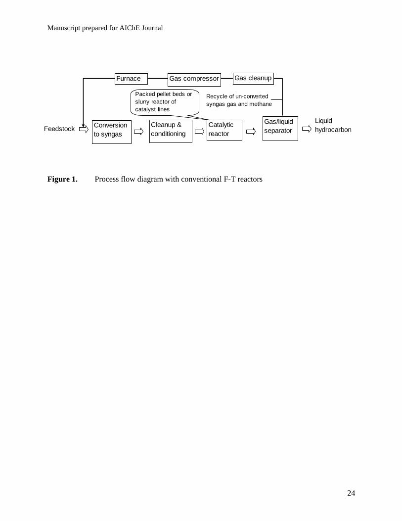
The F-T reactor itself represents only a small fraction of the capital cost in a conventional
F-T plant design. As illustrated in Figure 1, the conventional F-T reactor typically produces a
reaction mixture effluent containing a significant fraction of unconverted syngas and by products
such as methane in addition to the desired liquid product. The unconverted syngas and methane
have to be separated out of the product mixture and recycled back to the syngas generation
process unit. The recycling system increases plant operation complexity, and incurs more energy
consumption and capital cost. Since methane is a refractory compound for reforming reactions,
the recycled gas significantly increases duty of the upstream process steps, reforming reaction,
gas conditioning.
Present reactor and catalyst bed design concepts
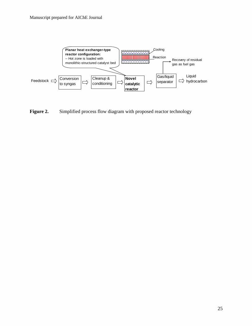
The goal of our study is to develop a new reactor technology that enables essentially
complete conversion of syngas in one pass without excessive production of methane and that
leads to a compact reactor unit suitable for small-scale operation. The proposed process flow
diagram is illustrated in Figure 2. The reactor is run under such conditions that >90% of syngas
feed is converted. In this way, complicated and expensive recycling system is avoided. The
reactor effluent is separated with relatively simple means into residual gas, liquid hydrocarbon
fuels, and water. The residual gas containing H2, CO, methane, and CO2 can be combusted as a
Manuscript prepared for AIChE Journal
4
fuel gas to provide energy to the unit operation, while the processing water can be re-used. The
hydrocarbon mixture is lumped as a liquid-phase product outlet that can be transported to a
centralized location, petrochemical plant or refinery for production of specific liquid fuels
and/or chemical products.
Obviously, the reactor design is a critical challenge to realize the above process
objectives. There must be good reasons why the current reactors are not run at complete one-pass
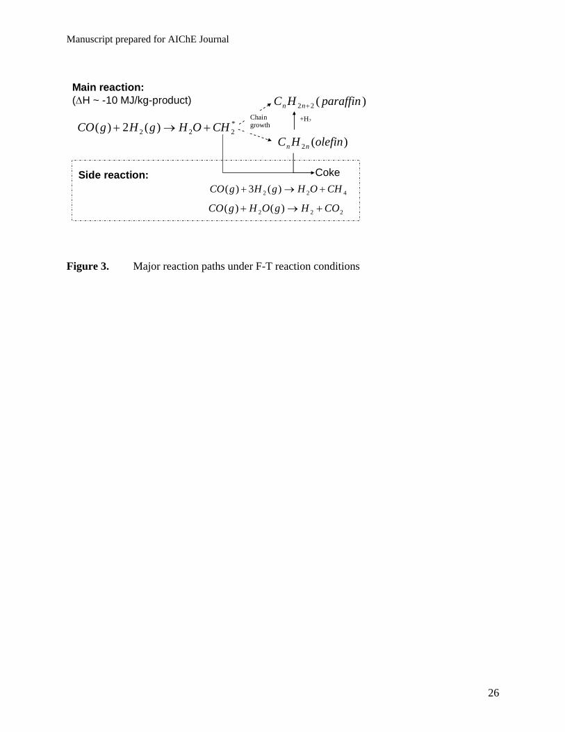
conversion. To aid discussion of the proposed new reactor design concept, a simplified reaction
network is given in Figure 3 to show characteristic of the syngas catalysis chemistry. The F-T
synthesis is a surface catalyzed polymerization process that uses CHx monomers, which are
formed by hydrogenation of adsorbed CO molecules, to produce hydrocarbons with a broad
range of chain length and functionality. In parallel to the desired polymerization reaction,
methane can be produced by the methanation reaction, and water-gas-shift reaction may occur to
produce CO2. Coke can be produced from either CO decomposition or un-controlled
polymerization reactions. Coking often causes catalyst deactivation15-16. The F-T reaction is
highly exothermic and can easily run away if the temperature is not effectively controlled. The F-
T reaction occurs under an environment of multiple physical phases and complex chemical
compositions, which include liquid-phase hydrocarbons such as waxes, water, light
hydrocarbons, inorganic gases (H2, CO, CO2), and solid catalysts. These are basic issues being
considered for design and development of new reactor technologies.
In the authors’ point of views, the limiting factors to run high one-pass conversion with
conventional reactors could be (i) high CH4 and CO2 selectivity; (ii) balance between flow
hydrodynamics and reaction kinetics, such as back mixing that makes high one-pass conversion
Manuscript prepared for AIChE Journal
5
fundamentally impossible with a single-stage reactor; (iii) accelerated catalyst deactivation; (iv)
lack of an effective catalyst; (v) effective temperature control of the catalyst bed.
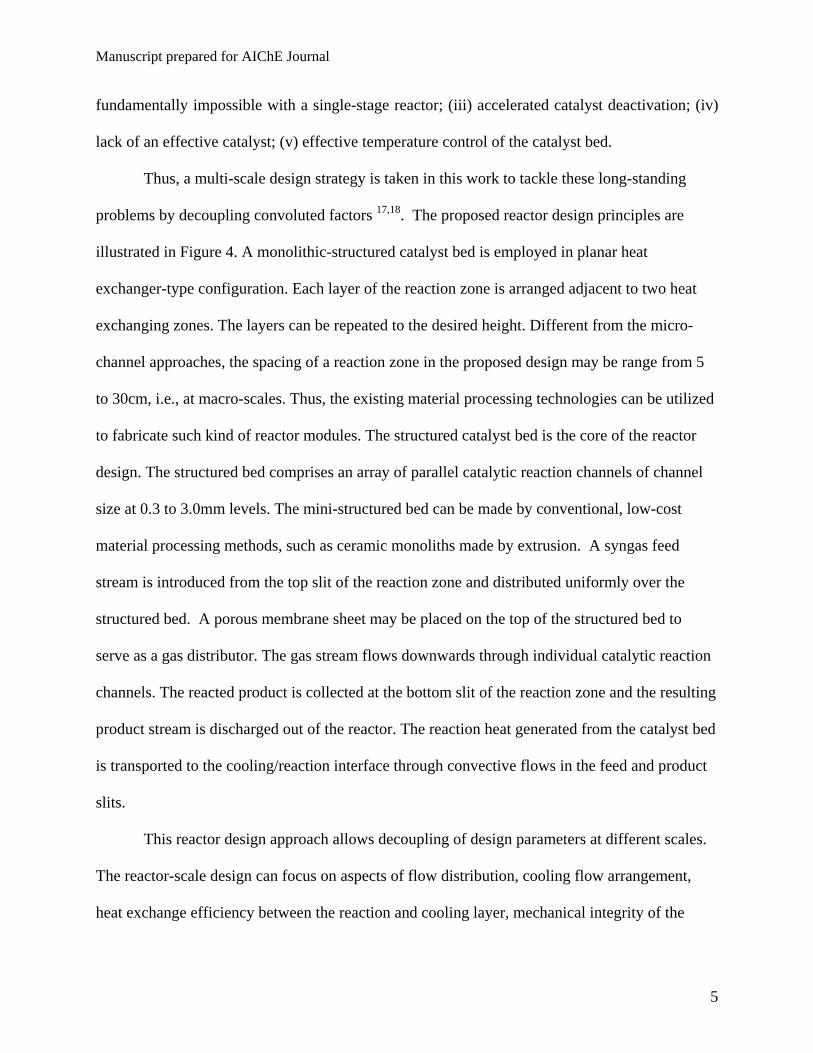
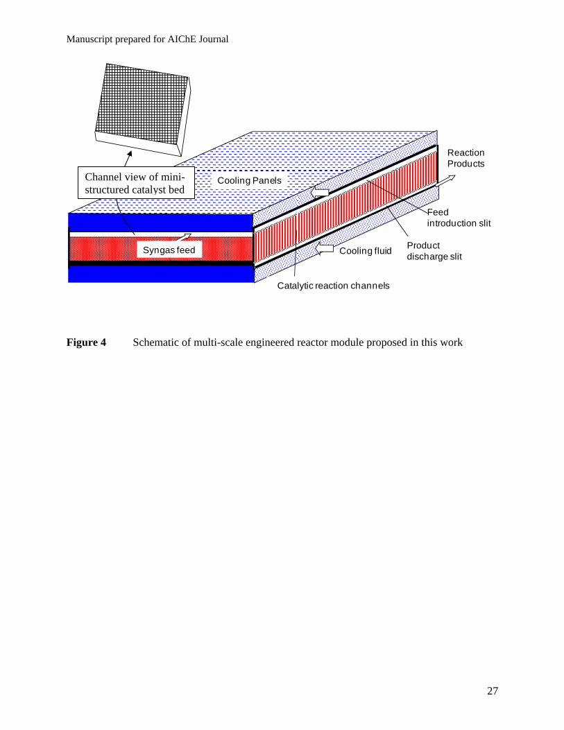
Thus, a multi-scale design strategy is taken in this work to tackle these long-standing
problems by decoupling convoluted factors 17,18. The proposed reactor design principles are
illustrated in Figure 4. A monolithic-structured catalyst bed is employed in planar heat
exchanger-type configuration. Each layer of the reaction zone is arranged adjacent to two heat
exchanging zones. The layers can be repeated to the desired height. Different from the micro-
channel approaches, the spacing of a reaction zone in the proposed design may be range from 5
to 30cm, i.e., at macro-scales. Thus, the existing material processing technologies can be utilized
to fabricate such kind of reactor modules. The structured catalyst bed is the core of the reactor
design. The structured bed comprises an array of parallel catalytic reaction channels of channel
size at 0.3 to 3.0mm levels. The mini-structured bed can be made by conventional, low-cost
material processing methods, such as ceramic monoliths made by extrusion. A syngas feed
stream is introduced from the top slit of the reaction zone and distributed uniformly over the
structured bed. A porous membrane sheet may be placed on the top of the structured bed to
serve as a gas distributor. The gas stream flows downwards through individual catalytic reaction
channels. The reacted product is collected at the bottom slit of the reaction zone and the resulting
product stream is discharged out of the reactor. The reaction heat generated from the catalyst bed
is transported to the cooling/reaction interface through convective flows in the feed and product
slits.
This reactor design approach allows decoupling of design parameters at different scales.
The reactor-scale design can focus on aspects of flow distribution, cooling flow arrangement,
heat exchange efficiency between the reaction and cooling layer, mechanical integrity of the
Manuscript prepared for AIChE Journal
6
reactor vessel, and mitigation of thermal and pressure stresses. In a single reaction zone, the
mini-structured bed serves both as a catalyst support and as a three-dimensional thermal
conduction matrix. The reaction heat generated at a reaction channel can be spread by thermal
conduction through the support. Compared to point-to-point contacts in a conventional bead-
packed catalyst bed, the continuous solid support structure should provide good thermal
conduction. Thus, the bed-scale design can address issues of thermal conductivity, open-frontal
area fraction, and channel size and geometry.
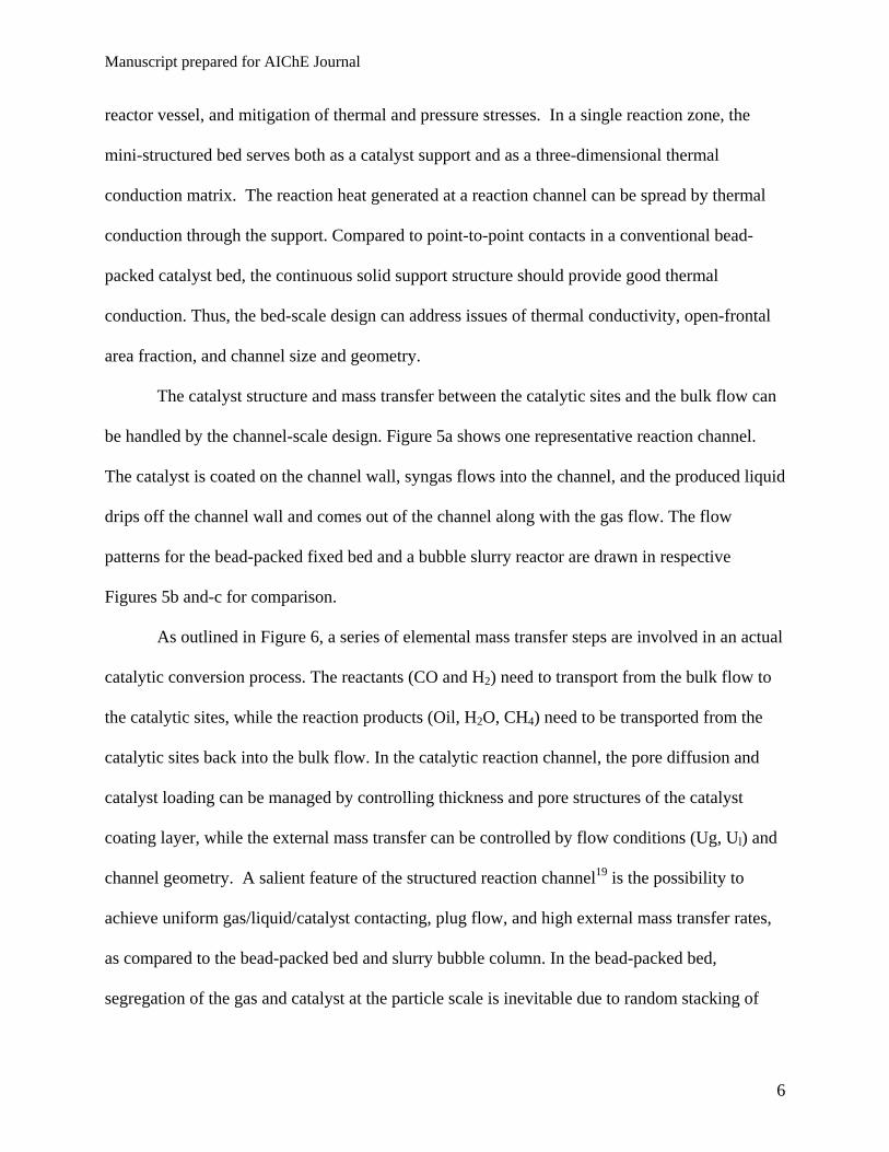
The catalyst structure and mass transfer between the catalytic sites and the bulk flow can
be handled by the channel-scale design. Figure 5a shows one representative reaction channel.
The catalyst is coated on the channel wall, syngas flows into the channel, and the produced liquid
drips off the channel wall and comes out of the channel along with the gas flow. The flow
patterns for the bead-packed fixed bed and a bubble slurry reactor are drawn in respective
Figures 5b and-c for comparison.
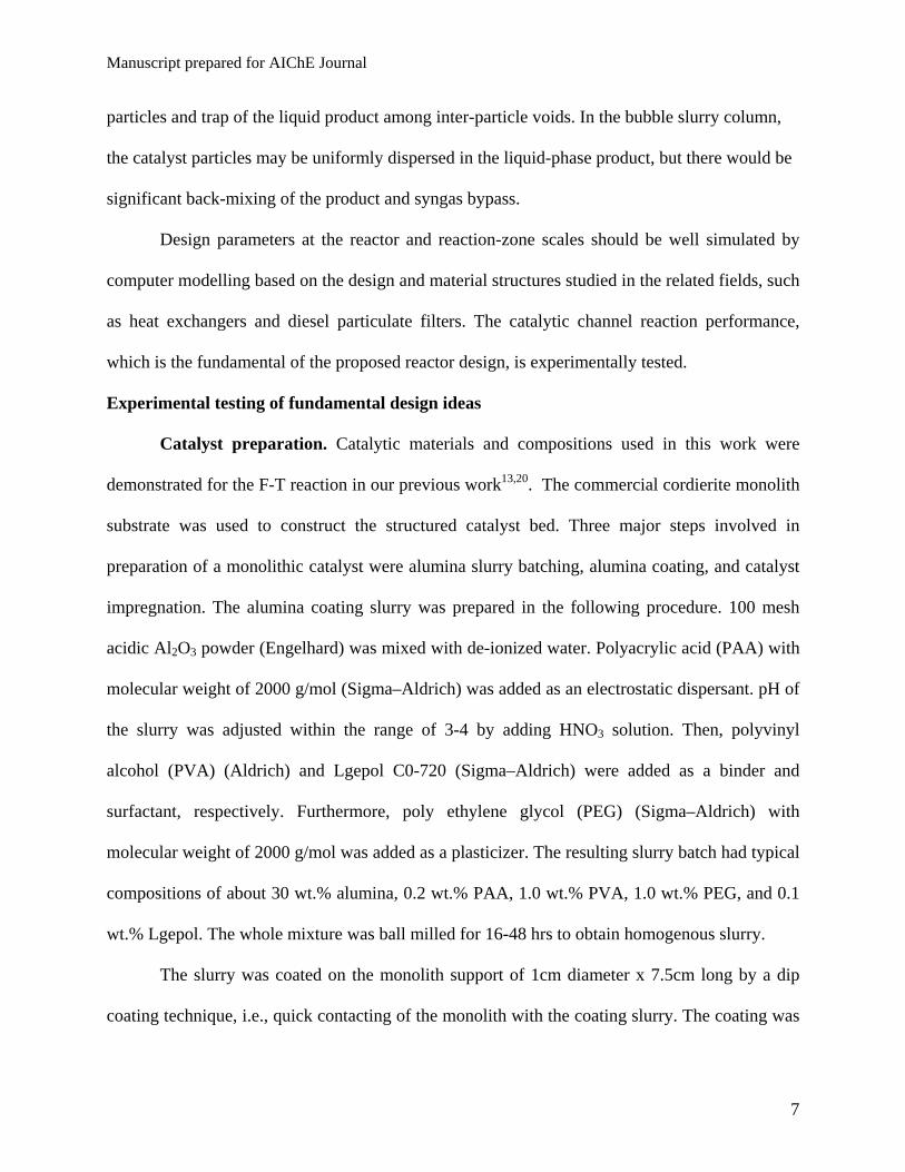
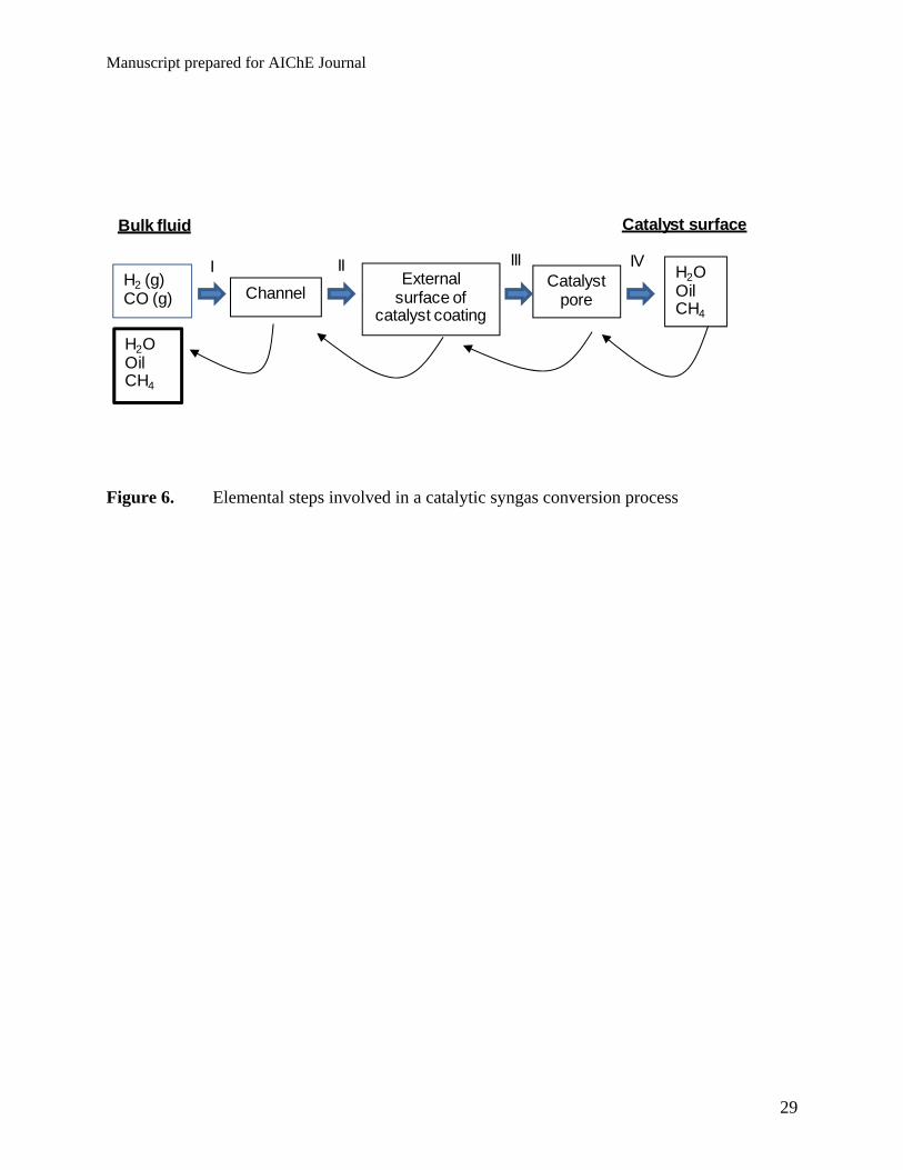
As outlined in Figure 6, a series of elemental mass transfer steps are involved in an actual
catalytic conversion process. The reactants (CO and H2) need to transport from the bulk flow to
the catalytic sites, while the reaction products (Oil, H2O, CH4) need to be transported from the
catalytic sites back into the bulk flow. In the catalytic reaction channel, the pore diffusion and
catalyst loading can be managed by controlling thickness and pore structures of the catalyst
coating layer, while the external mass transfer can be controlled by flow conditions (Ug, Ul) and
channel geometry. A salient feature of the structured reaction channel19 is the possibility to
achieve uniform gas/liquid/catalyst contacting, plug flow, and high external mass transfer rates,
as compared to the bead-packed bed and slurry bubble column. In the bead-packed bed,
segregation of the gas and catalyst at the particle scale is inevitable due to random stacking of
Manuscript prepared for AIChE Journal
7
particles and trap of the liquid product among inter-particle voids. In the bubble slurry column,
the catalyst particles may be uniformly dispersed in the liquid-phase product, but there would be
significant back-mixing of the product and syngas bypass.
Design parameters at the reactor and reaction-zone scales should be well simulated by
computer modelling based on the design and material structures studied in the related fields, such
as heat exchangers and diesel particulate filters. The catalytic channel reaction performance,
which is the fundamental of the proposed reactor design, is experimentally tested.
Experimental testing of fundamental design ideas
Catalyst preparation. Catalytic materials and compositions used in this work were
demonstrated for the F-T reaction in our previous work13,20. The commercial cordierite monolith
substrate was used to construct the structured catalyst bed. Three major steps involved in
preparation of a monolithic catalyst were alumina slurry batching, alumina coating, and catalyst
impregnation. The alumina coating slurry was prepared in the following procedure. 100 mesh
acidic Al2O3 powder (Engelhard) was mixed with de-ionized water. Polyacrylic acid (PAA) with
molecular weight of 2000 g/mol (Sigma–Aldrich) was added as an electrostatic dispersant. pH of
the slurry was adjusted within the range of 3-4 by adding HNO3 solution. Then, polyvinyl
alcohol (PVA) (Aldrich) and Lgepol C0-720 (Sigma–Aldrich) were added as a binder and
surfactant, respectively. Furthermore, poly ethylene glycol (PEG) (Sigma–Aldrich) with
molecular weight of 2000 g/mol was added as a plasticizer. The resulting slurry batch had typical
compositions of about 30 wt.% alumina, 0.2 wt.% PAA, 1.0 wt.% PVA, 1.0 wt.% PEG, and 0.1
wt.% Lgepol. The whole mixture was ball milled for 16-48 hrs to obtain homogenous slurry.
The slurry was coated on the monolith support of 1cm diameter x 7.5cm long by a dip
coating technique, i.e., quick contacting of the monolith with the coating slurry. The coating was
Manuscript prepared for AIChE Journal
8
repeated three times with inter-stage drying at 100oC. Finally, the coated monolith was calcined
at 550oC for 4 h at 5oC/min ramp rate for removal of all the organics and adhesion of the alumina
coating layer onto the support. On average, the alumina coating loading was 16.0 wt%.
The active catalyst phase was dispersed on the alumina coating with impregnation
technique. The impregnation solution was prepared by dissolving cobalt nitrate hexahydrate
(98% purity, Aldrich), perrhenic acid (Engelhard), and lanthanum nitrate hydrate into de-ionized
water. The monolith was wetted o incipient wetness by the solution. The wetted monolith was
dried in air at 90oC overnight and followed by calcinations at 350oC for 3 h. The impregnation
was repeated to obtain targeted catalyst loadings. The resulting Co, Re, and La loading on the
alumina coating was 17.8 wt. %, 3.3 wt. %, and 3.0 wt. %, respectively. The total catalyst metal
loading on the alumina basis was 24.1 wt. %, while the catalyst loading (metal +alumina) in the
whole monolith piece was 19.2 wt%.
For comparative testing, alumina-supported F-T catalyst particles were prepared by using
the same raw materials, procedures, and conditions as described above.
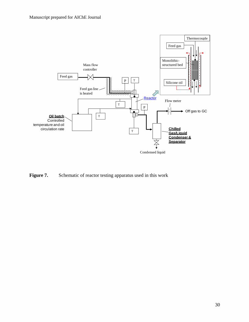
Catalytic reaction tests. Schematic of the reactor system used in this work was shown
in Figure 7. The monolith catalyst module was inserted into a ½” OD reactor tube of suitable ID
so that the gap between the tube wall and the monolith was comparable or less than the channel
size. This way of packing was necessary to minimize bypass of the flow along the channel wall.
The monolith catalyst was positioned in the middle of the reactor tube by two thermocouples at
the top and bottom. Thus, no other material was loaded into the reactor during testing of
monolith catalysts. The reactor tube was wrapped by an oil jacket to control the reaction
temperature, and the temperatures were measured at the bottom and top of the catalyst bed.
Manuscript prepared for AIChE Journal
9
For testing of catalyst particles, the catalyst particle was packed in the middle of a reactor
tube by using SiC particles. Similar to the reactor configuration for the monolith catalyst bed, the
thermocouple wells were placed at the top and bottom of the catalyst bed, respectively; and the
reactor tube was sheathed in an oil jacket for temperature control.
All the catalysts were activated by reduction in hydrogen prior to introduction of the
syngas. After the catalyst was reduced at about 400oC for 12 hours at 0.1MPa of H2, the reactor
temperature was cooled down under flowing hydrogen. Then, the reactor was pressurized to 25
bars with 5% H2 in helium. A syngas feed with H2/CO ratio of 2, unless specifically noted, was
introduced. 3 to 4 vol. % of Ar was spiked into the feed both as an internal standard and for
purge purpose. The reactor temperature was raised to the target value at 1oC/min. Hydrocarbon
and water in the reactor effluent were condensed in a chilled vessel under pressure. Non-
condensed gases were analyzed using an on-line gas chromatograph (Agilent QUADH G2981A
with Molsieve 5A, PoraPlol Q) to determine CO conversion and light product selectivity. The
condensed liquid products were analyzed in a HP 6890 connected with a DB-5 column. The
olefinic compounds were identified by GC-MS (HP 5973C), then quantified by a GC (HP 6890).
Conversion and selectivity are calculated based on the product gas analysis for CO, CO2, CH4,
C2H4, C2H6, C3H6, C3H8, and C4.
CO conversion is calculated by the following equation:
inCOin
exCOexinCOinCO xF
xFxFX
,0,
,,0,,0,
(1)
Selectivity toward to molecule i on carbon number basis is calculated as follows:
inCOinCO
iexiexi xFX
nxFS
,0,
,0,
(2)
Manuscript prepared for AIChE Journal
10
Weight-hourly space velocity is calculated based on CO mass feed rate for characterize
the catalyst activity:
Cat
CO
W
mWHSV (3)
Superficial gas linear velocity based on the reactor entrance condition is used to
characterize the channel flow conditions:
600
0,
R
toping APT
TFU (4)
Experimental results and discussion
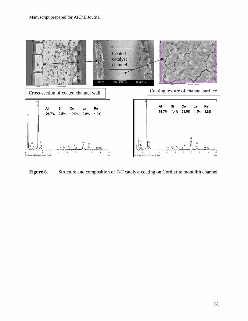
Catalyst coating. Uniformity of the catalyst coating on the monolith support was
examined by Scanning Electron Microscopy (SEM) and Energy-dispersive X-ray spectroscopy
(EDS) analysis. The coating surface texture and cross-section are shown in Figure 8. The channel
surface is fully covered by the catalyst, even though there are mud cracks on the coating.
Presence of a catalyst coating layer is evident in the cross-sectional view. The channel opening is
about 0.9mm, while the catalyst coating thickness is about 30 to 70µm. The EDS analysis shows
presence of Al, Si, Co, Re, and La elements. The Al and Si are attributed to the support, while
Co, Re, and La are impregnated catalyst metals. Presence of the catalyst metals on the channel
wall surface and at the middle point of the coating layer is confirmed. The SEM/EDS analyses
provide compositions at the localized spots. For a given global composition, variation of the
compositions among different spots is possible.
Reaction uniformity among monolith channels. For structured beds, uniform flow
distribution and reaction in all catalyst channels is a critical factor for effective catalyst
utilization and for minimization of side reactions. To check this, the reactor was quenched after
the reaction testing by stopping the feed gas flow and circulating cold silicone oil. The
Manuscript prepared for AIChE Journal
11
morphology of two spent monolith pieces unloaded from the reactor is shown in Figure 9. All the
channels facing the feed syngas in the upper piece of the monolith catalyst are fully open. The
monolith piece looks uniform, indicative to uniformity of the catalyst deposition and reaction.
The un-coated support would look grey, and the white wax would be trapped if there was
stagnant or dead space. All the channels in the lower piece of the monolith are filled with white
wax on the bottom, which indicate that the reaction (formation of wax) occurred among all the
channels. These observations suggest that the feed gas was distributed evenly among the catalyst
channels by simple stacking of two pieces of the monolith catalysts.
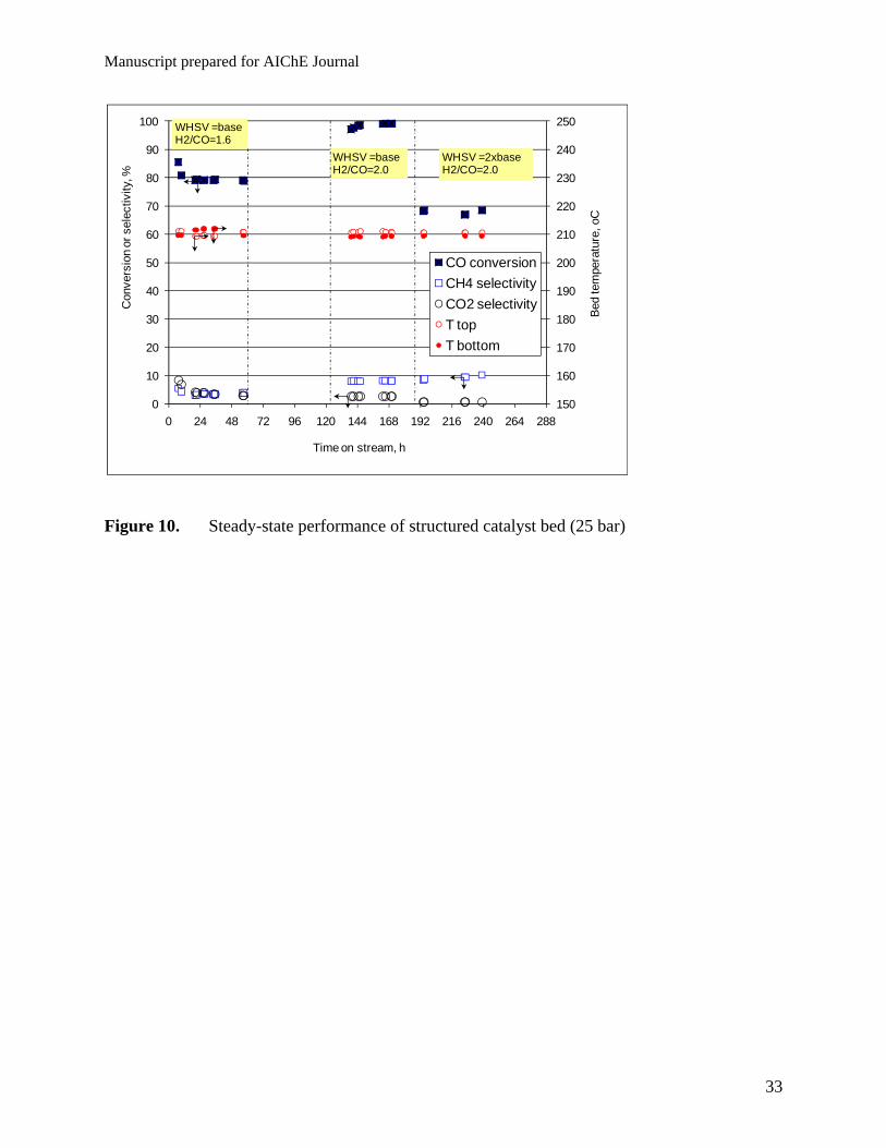
Exceptional performances of the monolithic-structured catalyst bed. Steady-state
reaction performances of the structured bed are shown by plots in Figure 10. First of all, the
temperature control was excellent. Given about 150mm of the bed height, the top and bottom
temperatures of the catalyst bed are consistent, and their differences are typically less than 2oC at
high CO conversion levels. Superficially, the bottom bed temperature could be much higher than
the top bed due to exothermic reactions in the confined catalyst channels. The small temperature
difference observed from the experiments can be explained by the thermal conduction through
the monolith support matrix and rapid heat transfer between the silicone oil and reactor tube. The
gap between the reactor tube wall and monolith body apparently did not impose limitation to the
radial heat transfer. This result confirms the possibility of the temperature control at a larger
spacing of the reaction zone in the proposed reactor design (Figure 4) than the diameter of
conventional tubular reactors, certainly orders of magnitude larger than the micro-channel
reactor spacing.
The structured bed had a quick response to changes of the reaction conditions, and
showed fairly good stability. The steady-state reaction could be reached within a few hours.
Manuscript prepared for AIChE Journal
12
Possibility to reach high CO conversion levels without excessive production of CH4 and CO2 is
clearly shown. The reactor was started with a syngas feed of H2/CO =1.6 containing 3.9 vol. %
Ar as an internal standard. Figure 10 shows about 79% CO conversion, which corresponds to
nearly complete H2 conversion. The higher CO conversion during the transient period was due to
the inventory hydrogen in the reactor system prior to the syngas introduction, since the catalyst
was pre-reduced in H2 gas. After the feed H2/CO ratio was adjusted to stoichiometric ratio of 2.0,
about 95-98% of CO conversion occurred under the same temperature, pressure, and space
velocity. Since the CO conversion was so high, nearly all the feed H2 and CO gas was consumed
and we had difficulty to maintain the reactor pressure with a very small flow of remaining Argon
gas. It should be noted that the methane and CO2 selectivity were only about 8 % and 2 %,
respectively. After the space velocity was doubled, under the same temperature and pressure, the
CO conversion was dropped to about 68%, the CH4 selectivity increased to about 9.5 %, while
the CO2 selectivity decreased to less than 0.5 %. Decline of the CO % conversion with increasing
space velocity can be explained by reduced residence time. However, variations of the CH4 and
CO2 selectivity with the space velocity could not be explained based on residence time.
To elucidate reaction behaviour of the structured bed, the reactor was loaded with other
two monolith catalyst pieces and tested under various reaction conditions after the steady-state
line-up. Excellent temperature control and >95% one-pass CO conversion at (CH4 +CO2)
selectivity less than 10 % were reproduced. Variations of CO conversion, CH4 selectivity, and
CO2 selectivity with reaction temperature under constant reactor pressure are plotted in Figure
11. The temperature is an average of the top and bottom bed readings. Several data points were
collected in a steady-state operation under each set of conditions, and the average values are
plotted. The closed symbols in Figure 11 are for WHSV of 2.0 1/h, while the open ones
Manuscript prepared for AIChE Journal
13
correspond to WHSV of 4.1 1/h. For a given WHSV, the CO conversion, CH4 selectivity, and
CO2 selectivity all increase with temperature. This is expected from the reaction kinetics.
However, comparison at different WHSVs tells a different story. At the same temperature, the
CO conversion and CO2 selectivity at the higher WHSV are lower than those values at the lower
WHSV, which is in line with reaction kinetics. The CH4 selectivity shows a very different
behaviour. At the same or similar temperature, the CH4 selectivity at the higher WHSV is the
same or higher than values at the lower WHSV. Obviously, such a variation cannot be explained
based on correlation of conversion with residence time.
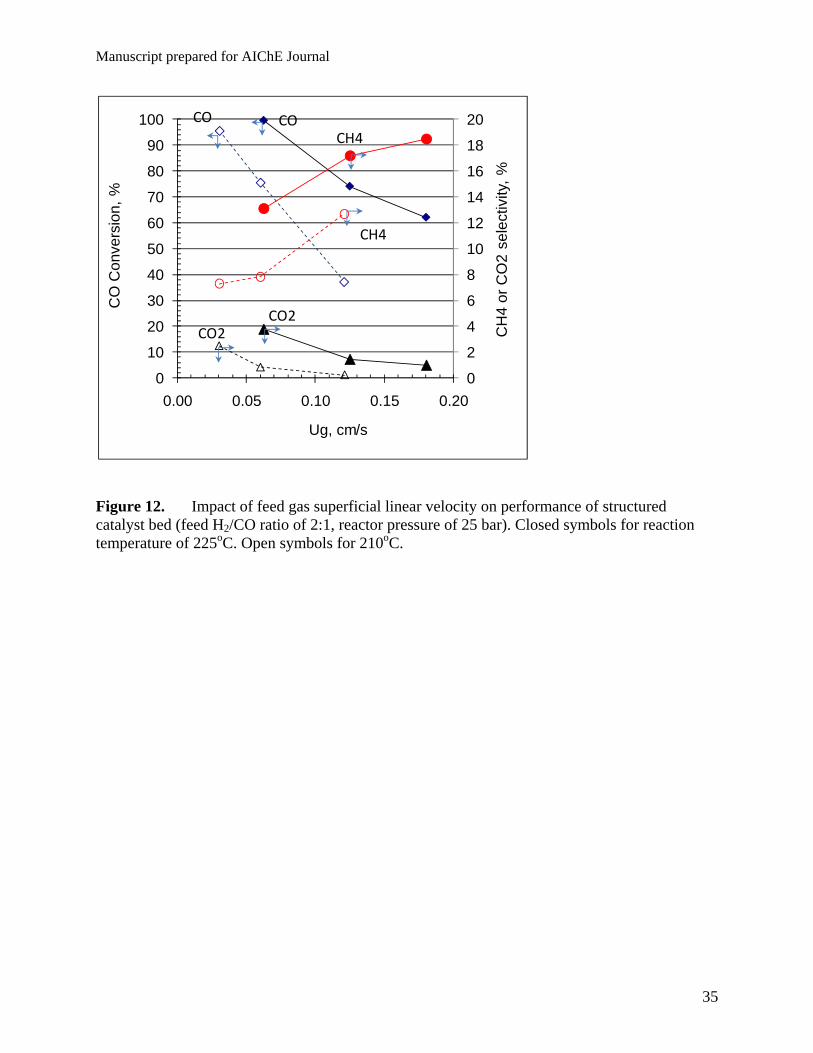
The un-usual selectivity behaviour is explained by channel flow hydrodynamics under
different reaction conditions. The flow conditions inside the channel are characterized by the gas
superficial linear velocity under the reactor entrance conditions. It is recognized that the gas flow
inside the channel would diminish while the liquid flow gradually increases along the channel
depth. Variations of CO conversion, CH4 selectivity, and CO2 selectivity with the superficial gas
velocity are shown in Figure 12, where the closed symbols and open symbols are for 225oC and
210oC reaction temperature, respectively. For a given temperature, the CO conversion decreases
with increasing the gas velocity. This is explained by reduced residence time, since the catalyst
bed height was fixed. The CO2 selectivity decreases with increase of the gas linear velocity.
However, the CH4 selectivity tends to increase with the gas linear velocity. The high CO
conversion and low CH4 selectivity are achieved at the low gas linear velocity. The gas linear
velocity becomes one critical design parameter for the proposed reactor concept. Thus, the plate-
like catalyst bed configuration is presented in Figure 4. Such a bed would allow low gas linear
velocities at high gas feed flow rates. The hydrodynamic pattern inside the catalyst channel
could be very complex, due to presence of multiple phases. The proposed design allows scaling
Manuscript prepared for AIChE Journal
14
of the channel flow hydrodynamics from the small-scale laboratory reactor to any size of the
reactor.
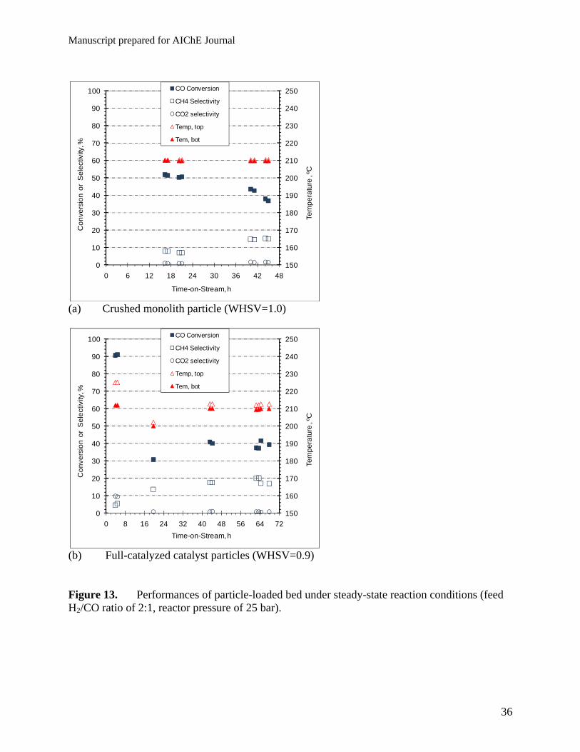
Performances of catalyst particle beds. For comparison purposes, the line-out
behaviour of particle-loaded catalyst beds is shown in Figure 13. The same monolith catalyst as
used above was crushed and sieved into 60-200 mesh (~170um). The crushed particle was loaded
into a reactor tube and sandwiched by a layer of SiC particles on the top and bottom. The
crushed particle bed was started in the same procedure as used for the structured bed. Figure 13a
shows variations of CO conversion, CH4 selectivity, and CO2 selectivity with time on stream.
The top and bottom bed temperatures were maintained constantly at 210oC. However, it took a
much longer time to reach the conversion plateau than the structured bed. The CO conversion
declined with time, while the CH4 selectivity increased with time. These trends suggest that
formation of CH4 is favoured on the deactivated catalyst. The CO2 selectivity was very low. The
crushed monolith catalyst particle represents an egg-shell catalyst structure, i.e., an active
catalyst layer coated on an inert support. Comparative testing results of fully-catalyzed catalyst
particles are shown in Figure 13b to further show performance characteristic of the particle-
loaded catalyst bed. This catalyst particle of + 200 mesh size (~45µm) was prepared with the
same materials and same procedures as used for the preparation of the catalyst coatings on the
monolith. The catalyst particle was loaded into a reactor tube with the SiC particle diluent at
volume ratio of 1:1. It was experienced that the catalyst bed temperatures varied erratically at
the beginning of testing and made it difficult to control the bed temperature. The initial data
points show nearly 90% CO conversion and about 5 % CH4 selectivity. However, as the bed
temperatures got stabilized at 210oC, the CO conversion declined and the CH4 selectivity
increased with time. These trends point out the same conclusion as conjectured with the crushed
Manuscript prepared for AIChE Journal
15
monolith particle bed that the deactivated catalyst causes lower CO conversion and higher CH4
selectivity.
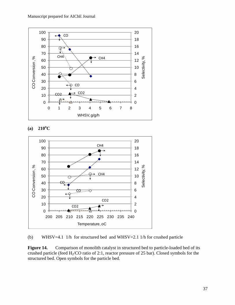
Comparison of the structured bed to the particle bed. To avoid complication of the
catalyst preparation, the same monolith catalyst in the structured bed is compared to the crushed
particle bed in Figures 14a and –b. At the same reaction temperature, Figure 14a shows that the
structured bed gives much higher steady-state CO conversion than the crushed particle bed. The
CO conversion activity of the structured bed is about four times that of the crushed particle bed.
The CH4 selectivity for the crushed particle bed decreased with increasing space velocity. The
increase of the CH4 selectivity with space velocity for the structured bed was explained above
attributed to the increased gas superficial linear velocity. The structured bed also showed a
higher CO conversion activity than the crushed particle bed at a higher temperature. Figure 14b
shows that under constant space velocity, the CO conversion and CH4 selectivity increase with
temperature for both beds. Even though the space velocity for the structured bed is about two
times of the crushed particle bed, the CO conversion with the structured bed is significantly
higher than the crushed particle bed.
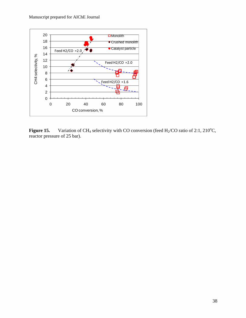
A plot of CH4 selectivity versus CO conversion is used to compare the CH4 selectivity of
different catalyst beds. By excluding transient data points, data points at different aging times
and different space velocities at temperature about 210oC are plotted in Figure 15. I can be seen
that the CH4 selectivity increases proportionally with the CO conversion for both the crushed
particle and catalyst particle bed. The CH4 selectivity would become too high to be practical if
that trend is extrapolated to high CO conversion levels, such as >90%. This selectivity versus
conversion paradox is breached by using the structured bed. Figure 15 shows that the CH4
Manuscript prepared for AIChE Journal
16
selectivity can be controlled below 10% at about >95% of CO conversion. Clearly, the un-usual
behaviour of the structured bed calls for a new reaction engineering model.
Pore wetness and surface perspiration model for F-T reaction. This work reveals
dramatic impacts of the catalyst bed design and operation on F-T reaction performances for a
given catalyst material. Clearly, the F-T reaction activity, selectivity, and stability are not merely
a catalysis problem, i.e., tailoring of catalyst pore structures, compositions and active sites. The
ways how a catalyst is loaded into a reactor vessel and tested play a significant role in the
resulting reaction performances. Based on our research results and literature analysis, we propose
a new model to guide the F-T reactor designs and operation, as depicted in Figure 5a.
Characteristic of the proposed model and preferred catalyst bed designs is discussed in the
following three aspects.
(i) Structured mini-channel flow to have a plug flow pattern and avoid any
dead/stagnant space in the bed. The plug flow is necessary to eliminate any back-mixing and
achieve high one-pass conversion. Minimization of the dead space would be helpful to prevent
the catalyst deactivation from excessive reactions -coking.
(ii) Fully-wetted catalyst pores to prevent the catalyst surface from formation of dry
or hot spots. Methane formation on a dry catalyst can be very fast, due to fast gas diffusion and
rapid heating up of the local spots. The reaction can easily run away on a dry catalyst. When the
catalyst pore is wetted by a liquid fluid, diffusion rates of H2 and CO reactants are slowed down
and thermal conductivity of the catalyst is significantly enhanced. F-T reaction kinetics is slower
than methanation. Thus, the pore wetness would quench the methanation reaction without
significant reduction of the F-T reaction rate. During a dynamic reaction process, the pore
wetness is determined by the formation rate of the liquid product and drying (or liquid
Manuscript prepared for AIChE Journal
17
evaporation) rate. For a given temperature and pressure, the drying rate will be affected by the
gas flow rate inside the channel. Thus, the gas linear velocity inside the channel should be
controlled below a certain level in order to keep the catalyst surface stay wet. This mechanism
explains the decreased methane selectivity with decreasing gas linear velocity, which is observed
in this work.
(iii) Discharge of the liquid product from the catalyst pore through perspiration to
avoid coverage of the catalyst surface by a thick liquid layer. If the liquid product needs to
be washed away from the catalyst surface, a thick liquid layer could be formed that may
drastically reduce diffusion rate of H2 and CO gas from the channel flow into the catalyst pore.
In a perspiration process, the catalyst surface can stay wet without a thick liquid layer on
majority of the surface. The product liquid perspired from the catalyst pore gradually
accumulates on the catalyst surface and coalesces into a droplet. The droplet is dislodged from
the catalyst surface by gravity and/or by gas dragging when it grows to a certain size. This
mechanism explains four times of the higher CO conversion activity obtained with the structured
bed than with the crushed particle bed. Since the same catalyst material was used, the enhanced
activity must result from enhanced external mass transfer of H2 and CO, i.e., mass transfer from
the bulk flow onto the catalyst external surface. The pore diffusion length in the structured bed
should be the same as in the crushed particle, because the catalyst coating was fixed. Even
though the crushed particle provides a much higher geometric surface area for external mass
transfer than the channel surface in the structured form, there could be a smaller effective
gas/liquid mass transfer area and/or thicker liquid film in the packed bed of the crushed particle
than in the structured channel. This is explained with the illustration in Figure 5b. The liquid
trapped in the inter-particle voids may become stagnant so that there is no ideal
Manuscript prepared for AIChE Journal
18
gas/liquid/particle contact on individual particle basis. In a random-packed particle bed, the
catalyst particles behave as an aggregate, cluster or a group. The equivalent size of such an
aggregate would depend on the bed packing and reaction conditions, and could be orders of
magnitude larger than the individual particle size.
The physical model presented here can be further elaborated with mathematical equations
in the future work. This reaction engineering model and the structured bed design would be
applied to syngas-to-liquid conversion processes other than the F-T reaction. Effective
temperature control, high CO conversion activity, and low CH4 selectivity are common
performance characteristic for a gas-to-liquid conversion process. In this work, we use one
catalyst material and monolithic support to elucidate the structured bed design ideas. The
materials and structures of both catalyst and support can certainly be optimized to enhance the
reaction performance of the structured bed. For example, a monolithic support of the higher
geometric surface area and more catalyst loading can be used to increase the reactor throughput.
The monolithic support can be made of metallic or ceramic materials.
5. Conclusion
Structured catalyst bed & reactor design concepts are presented in this work to address
long-term dilemma for the gas-to-liquid catalytic reaction process, better temperature control,
better catalyst activity and stability, lower CH4 selectivity, ease for scale-up. For the given
catalyst material and catalysis chemistry, all these problems are fundamentally related to mass
and heat transfer at different scales. The proposed approach provides a way for decoupling of
convoluted design parameters so that different aspects of the reactor design and operation
problems can be tackled through designs at the reactor-scale, catalyst bed-scale, and individual
channel-scale, respectively.
Manuscript prepared for AIChE Journal
19
The fundamental idea of the proposed reactor design is demonstrated for the F-T catalytic
reaction by using known catalyst and support materials, a Re-Co/alumina catalyst coated on a
cordierite monolith support. At a H2/CO feed ratio of 2, ~95% CO conversion and <10% CH4
selectivity was obtained with the monolithic-structured bed. The structured bed shows about four
times of higher CO conversion activity than the crushed particle bed of the same catalyst. These
levels of high CO conversion and low CH4 selectivity were not obtainable by using the
conventional particle bed. The gas superficial linear velocity was found as one critical design and
operation parameter for the structured bed. This funding makes it possible to scale up
hydrodynamics directly from small laboratory-bench testing units to practically any sizes with
the proposed reactor design configuration.
The pore wetness and surface perspiration model is proposed to explain the present
experimental results and observations, and to rationalize new reactor designs for gas-to-liquid
reaction processes.
Manuscript prepared for AIChE Journal
20
Acknowledgment
This work was supported under laboratory-directed research and development (LDRD) program
of PNNL by Energy Conversion Initiative and Energy & Environmental Directorate.
Pacific Northwest National Laboratory (PNNL) is operated by Battelle for the Department of
Energy. This work was partially supported by PNNL Energy Conversion Initiative.
Manuscript prepared for AIChE Journal
21
Nomenclature
AR = cross-sectional area of reactor tube, cm2
Fin,0 = Feed gas flow rate under standard gas conditions, sccm
Fex,0 = Residual gas flow of reactor effluent after the liquid condenser, sccm
mCO = mass flow rate of CO fed into the reactor, g/h
ni = number of carbon atoms in molecule specie i, i=1 for CO2 and CH4.
P = reactor pressure, bar
Si = Selectivity toward gas specie i, i = CH4, CO2, C2H4, C2H6, C3H6, or C3H8
Ttop = Reactor top bed temperature, K
T0 = temperature under standard gas conditions, 293K
Ug = superficial gas linear velocity under reactor entrance conditions, cm/s
Wcat = Net catalyst weight (alumina + metals), g
xCO,ex = Molar fraction of CO in residual gas
xCO,in = Molar fraction of CO in feed gas
xCO,in = Molar fraction of CO in feed gas
xCO,ex = Molar fraction of CO in residual gas
xi,ex = Molar fraction of molecule i in residual gas
XCO = conversion of CO
Manuscript prepared for AIChE Journal
22
Literature cited
1. Hoek A. 2003. The Shell middle distillate synthesis process Facts, Technology and Perspective. Presentation at CatCon2003, Houston, May 5-6th.
2. Sehabiague L, Lemoine R, Behkish A, Heintz YJ, Sanoja M, Oukaci R, Morsi BI. Modeling and optimization of a large-scale slurry bubble column reactor for producing 10000 bb/day of Fischer-Tropsch liquid hydrocarbons. J. of the Chinese Institute of Chemical Engineers. 2008; 39:169-179.
3. Iglesia E, Soled SL,Baumgartner JE, Reyes SC. Synthesis and catalytic properties of eggshell cobalt catalysts for the Fischer-Tropsch synthesis. J. of Catal. 1995; 153:108-122.
4. Iglesia E. Design, synthesis, and use of cobalt-based Fischer-Tropsch synthesis catalysts. Appl. Catal. A: General. 1997; 161: 59-78.
5. Dasgupta, D, Wiltowski T. Enhancing gas phase Fischer-Tropsch synthesis catalyst design. FUEL. 2011; 90 (1): 174-181.
6. Bukur DB, Carreto-Vazquez VH, Victor H, Ma WP. Catalytic performance and attrition strength of spray-dried iron catalysts for slurry phase Fischer-Tropsch synthesis. Applied Catalysis A-General. 2010; 388 (1-2):240-247.
7. Zhang QH, Kang JC, Wang Y. Development of Novel Catalysts for Fischer-Tropsch Synthesis: Tuning the Product Selectivity. CHEMCATCHEM. 2010; 2 (9): 1030-1058.
8. Sie ST, Krisha R. Fundamentals and selection of advanced Fischer-Tropsch reactors. Appl. Catal. A. 1999; 186:55-70.
9. Hulet C, Clement P, Tochon P, Schweich D, Dromard N, Anfray J. Literature Review on Heat Transfer in Two- and Three-Phase Bubble Columns. International Journal Of Chemical Reactor Engineering. 2009; 7: Art. No. R1.
10. Lu XJ, Hildebrandt D, Liu XY, Glasser D. Making Sense of the Fischer-Tropsch Synthesis Reaction: Start-Up. Industrial & Engineering Chemistry Research. 2010; 49 (20): 9753-9758.
11. Zhu XW, Lu XJ, Liu XY, Hildebrandt D, Glasser D. Study of Radial Heat Transfer in a Tubular Fischer-Tropsch Synthesis Reactor. Industrial & Engineering Chemistry Research. 2010; 49 (21): 10682-10688.
12. Lee M, Rumbold SO. Industrial microchannel devices –where are we today? First International Conference on Microchannels and Minichannels, ICMM2003-1101, Rochester, New York, USA, April 24-25, 2003.
13. Cao C, Hu J, Li S, Wilcox W, Wang Y. Intensified Fischer-Tropsch Synthesis Process with Microchannel Catalytic Reactors. Catal. Today. Catalysis Today. 2009; 140:149–156.
14. Knochen J, Guttel R, Knobloch C, Turek T. Fischer-Tropsch synthesis in milli-structured fixed-bed reactors: Experimental study and scale-up considerations. Chemical Engineering and Processing. 2010; 49 (9): 958-964.
Manuscript prepared for AIChE Journal
23
15. Tsakoumis NE, Ronning M, Borg O, Rytter E, Holmen A. Deactivation of cobalt based Fischer-Tropsch catalysts: A review. Catalysis Today. 2010; 154 (3-4): 162-182.
16. Nam I, Seo JG, Hwang S, Song IK. Deactivation behaviors of hybrid Fischer-Tropsch catalysts in the production of middle distillate from synthesis gas in a dual-bed reactor. Research on Chemical Intermediates. 2010; 36 (6-7): 685-692.
17. Li J, Kwauk M. Exploring complex systems in chemical engineering – the multi-scale methodology. Chem. Eng. Sci. 2003; 58:521-535.
18. Liu W. Multi-scale Catalyst Design. Chem. Eng. Sci. 2007; 62: 3502-3512.
19. Liu W. Mini-Structured Catalyst Bed for Gas-Liquid-Solid Multiphase Catalytic Reaction. AIChE J. 2002;48(7): 1519-32.
20. Liu W, Hu J, Wang Y. Fischer-Tropsch Synthesis on Ceramic Monolith-structured Catalysts. Catal. Today. 2009 ; 140: 142–148
Manuscript prepared for AIChE Journal
24
Figure 1. Process flow diagram with conventional F-T reactors
Conversion to syngas
Cleanup & conditioning
Catalytic reactor
Gas/liquid separator
Liquid hydrocarbonFeedstock
Furnace Gas compressor
Recycle of un-converted syngas gas and methane
Gas cleanup
Packed pellet beds or slurry reactor of catalyst fines
Manuscript prepared for AIChE Journal
25
Figure 2. Simplified process flow diagram with proposed reactor technology
Conversion to syngas
Cleanup & conditioning
Novel
catalytic reactor
Gas/liquid separator
Liquid hydrocarbonFeedstock
Recovery of residual gas as fuel gas
Planar heat exchanger-type reactor configuration:-- Hot zone is loaded with monolithic-structured catalyst bed
Cooling
Reaction
Manuscript prepared for AIChE Journal
26
Figure 3. Major reaction paths under F-T reaction conditions
*222 )(2)( CHOHgHgCO
)(22 paraffinHC nn
)(2 olefinHC nn
+H2Chain growth
Main reaction: (H ~ -10 MJ/kg-product)
Coke
422 )(3)( CHOHgHgCO
222 )()( COHgOHgCO
Side reaction:
Manuscript prepared for AIChE Journal
27
Figure 4 Schematic of multi-scale engineered reactor module proposed in this work
Syngas feed Cooling fluid
Reaction Products
Catalytic reaction channels
Cooling Panels
Feed introduction slit
Product discharge slit
Channel view of mini-structured catalyst bed
Manuscript prepared for AIChE Journal
28
(a). Proposed channel flow reaction model
(b) Packed catalyst beads (or particles) (c) Slurry bubble column Figure 5. New reaction engineering model in comparison to other catalyst beds
Support structure
Catalystcoating
SyngasCatalyst pore
Liquid product
SyngasSyngas
Manuscript prepared for AIChE Journal
29
Figure 6. Elemental steps involved in a catalytic syngas conversion process
Bulk fluid
Channel External
surface of catalyst coating
Catalyst pore
H2OOilCH4
H2 (g)CO (g)
H2OOilCH4
I IVIIIII
Catalyst surface
Manuscript prepared for AIChE Journal
30
Figure 7. Schematic of reactor testing apparatus used in this work
Feed gas
Oil batch Controlled
temperature and oil circulation rate
Reactor
Feed gas line is heated
T
T
P
P
Chilled Gas/Liquid Condenser & Separator
Condensed liquid
Off gas to GC
Flow meter
Mass flow controller
T
T
Thermocouple
Monolithic-structured bed
Silicone oil
Feed gas
Manuscript prepared for AIChE Journal
31
Figure 8. Structure and composition of F-T catalyst coating on Cordierite monolith channel
Coated catalyst channel
Cross-section of coated channel wall Coating texture of channel surface
Manuscript prepared for AIChE Journal
32
(a). Upper piece (b) Lower piece Figure 9. Morphologies of monolith catalyst pieces after 45-day testing
Manuscript prepared for AIChE Journal
33
Figure 10. Steady-state performance of structured catalyst bed (25 bar)
150
160
170
180
190
200
210
220
230
240
250
0
10
20
30
40
50
60
70
80
90
100
0 24 48 72 96 120 144 168 192 216 240 264 288
Bed
tem
pera
ture
, oC
Con
vers
ion
or s
elec
tivity
, %
Time on stream, h
CO conversion
CH4 selectivity
CO2 selectivity
T top
T bottom
WHSV =baseH2/CO=1.6
WHSV =baseH2/CO=2.0
WHSV =2xbaseH2/CO=2.0
Manuscript prepared for AIChE Journal
34
Figure 11 Impact of reaction temperature on performance of structured catalyst bed (feed H2/CO ratio of 2:1, reactor pressure of 25 bar). Closed symbols for WHSV=2.0 1/h. Open symbols for WHSV=4.1 1/h
0
2
4
6
8
10
12
14
16
18
20
0
10
20
30
40
50
60
70
80
90
100
205 210 215 220 225 230
CH
4 or
CO
2 se
lect
ivity
, %
CO
Con
vers
ion,
%
Temp, oC
CO
CH4
CO2
CO CH4
CO2
Manuscript prepared for AIChE Journal
35
Figure 12. Impact of feed gas superficial linear velocity on performance of structured catalyst bed (feed H2/CO ratio of 2:1, reactor pressure of 25 bar). Closed symbols for reaction temperature of 225oC. Open symbols for 210oC.
0
2
4
6
8
10
12
14
16
18
20
0
10
20
30
40
50
60
70
80
90
100
0.00 0.05 0.10 0.15 0.20
CH
4 or
CO
2 se
lect
ivity
, %
CO
Con
vers
ion,
%
Ug, cm/s
CO
CH4
CO2
CO
CH4
CO2
Manuscript prepared for AIChE Journal
36
(a) Crushed monolith particle (WHSV=1.0)
(b) Full-catalyzed catalyst particles (WHSV=0.9) Figure 13. Performances of particle-loaded bed under steady-state reaction conditions (feed H2/CO ratio of 2:1, reactor pressure of 25 bar).
150
160
170
180
190
200
210
220
230
240
250
0
10
20
30
40
50
60
70
80
90
100
0 6 12 18 24 30 36 42 48
Tem
pe
ratu
re ,
ºC
Co
nve
rsio
n o
r S
ele
ctiv
ity, %
Time-on-Stream, h
CO Conversion
CH4 Selectivity
CO2 selectivity
Temp, top
Tem, bot
150
160
170
180
190
200
210
220
230
240
250
0
10
20
30
40
50
60
70
80
90
100
0 8 16 24 32 40 48 56 64 72
Tem
pe
ratu
re ,
ºC
Co
nve
rsio
n o
r S
ele
ctiv
ity, %
Time-on-Stream, h
CO Conversion
CH4 Selectivity
CO2 selectivity
Temp, top
Tem, bot
Manuscript prepared for AIChE Journal
37
(a) 210oC
(b) WHSV=4.1 1/h for structured bed and WHSV=2.1 1/h for crushed particle Figure 14. Comparison of monolith catalyst in structured bed to particle-loaded bed of its crushed particle (feed H2/CO ratio of 2:1, reactor pressure of 25 bar). Closed symbols for the structured bed. Open symbols for the particle bed.
0
2
4
6
8
10
12
14
16
18
20
0
10
20
30
40
50
60
70
80
90
100
0 1 2 3 4 5 6 7 8
Se
lect
ivity
, %
CO
Co
nve
rsio
n ,
%
WHSV, g/g/h
CO
CO
CH4CH4
CO2CO2
0
2
4
6
8
10
12
14
16
18
20
0
10
20
30
40
50
60
70
80
90
100
200 205 210 215 220 225 230 235 240
Se
lect
ivity
, %
CO
Co
nve
rsio
n ,
%
Temperature, oC
CO
CO
CH4
CH4
CO2
CO2
Manuscript prepared for AIChE Journal
38
Figure 15. Variation of CH4 selectivity with CO conversion (feed H2/CO ratio of 2:1, 210oC, reactor pressure of 25 bar).