A COMPARISION OF RESONANT CONVERTERS USING FUELCELL AS AN INPUT SOURCE I. INTRODUCTION In recent years, the issue of renewable energy is becoming significant due to increasing power demand, instability of rising oil prices and environmental problems. Among the various renewable energy sources Fuel cell technology has been gaining more popularity due to their higher efficiency, cleanliness and cost effective supply of powers demanded by the consumers. A Fuel cell is an energy conversion device that converts the chemical energy of a reaction directly into electricity with by-product of water and heat. Fuel cells are classified according to choice of electrolyte and fuel, further fuel cells are classified based on operating temperature. Abbreviations ZVS Zero Voltage Switching ZCS Zero Current Switching PWM Pulse Width Modulation EMI Electro Magnetic Induction SRC Series Resonant Converter PRC Parallel Resonant Converter SPRC Series-Parallel Resonant Converter FCT Fuel Cell Technology Different types of fuel cells are categorized according to the electrolyte used: Proton-Exchange- Membrane (PEM) (also called Polymer Electrolyte Membrane) fuel cells, alkaline fuel cells, International Journal of Latest Trends in Engineering and Technology Vol.(8)Issue(1), pp.290-299 DOI: http://dx.doi.org/10.21172/1.81.038 e-ISSN:2278-621X Abstract: An analysis has been made to prepare fuel cell in Matlab/Simulink environment in a system that is used in Electrolyzer application. This paper focuses on designing of Series, parallel, series -parallel Resonant Converter using fuel cell as an Input source.One key advantage that fuel cells have over battery technology is the seemingly unlimited amount of power that can be produced as long as fuel is supplied. A comparison is also done among all the type of converters and is shown that Series-Parallel resonant converter has less switching losses compared to the other type of converters. Keywords: Fuel cell, Resonant Converter, Zero Voltage Switching, Zero current switching, Pulse Width Modulation
Transcript
A COMPARISION OF RESONANT CONVERTERS USING FUELCELL AS AN INPUT SOURCE I. INTRODUCTION In recent years, the issue of renewable energy is becoming significant due to increasing power demand, instability of rising oil prices and environmental problems. Among the various renewable energy sources Fuel cell technology has been gaining more popularity due to their higher efficiency, cleanliness and cost effective supply of powers demanded by the consumers. A Fuel cell is an energy conversion device that converts the chemical energy of a reaction directly into electricity with by-product of water and heat. Fuel cells are classified according to choice of electrolyte and fuel, further fuel cells are classified based on operating temperature. Abbreviations
ZVS Zero Voltage Switching ZCS Zero Current Switching PWM Pulse Width Modulation EMI Electro Magnetic Induction SRC Series Resonant Converter PRC Parallel Resonant Converter SPRC Series-Parallel Resonant Converter FCT Fuel Cell Technology
Different types of fuel cells are categorized according to the electrolyte used: Proton-Exchange-Membrane (PEM) (also called Polymer Electrolyte Membrane) fuel cells, alkaline fuel cells,
International Journal of Latest Trends in Engineering and Technology Vol.(8)Issue(1), pp.290-299
Abstract: An analysis has been made to prepare fuel cell in Matlab/Simulink environment in a system that is used in Electrolyzer application. This paper focuses on designing of Series, parallel, series -parallel Resonant Converter using fuel cell as an Input source.One key advantage that fuel cells have over battery technology is the seemingly unlimited amount of power that can be produced as long as fuel is supplied. A comparison is also done among all the type of converters and is shown that Series-Parallel resonant converter has less switching losses compared to the other type of converters. Keywords: Fuel cell, Resonant Converter, Zero Voltage Switching, Zero current switching, Pulse Width Modulation
A Comparision Of Resonant Converters Using Fuelcell As An Input Source 291
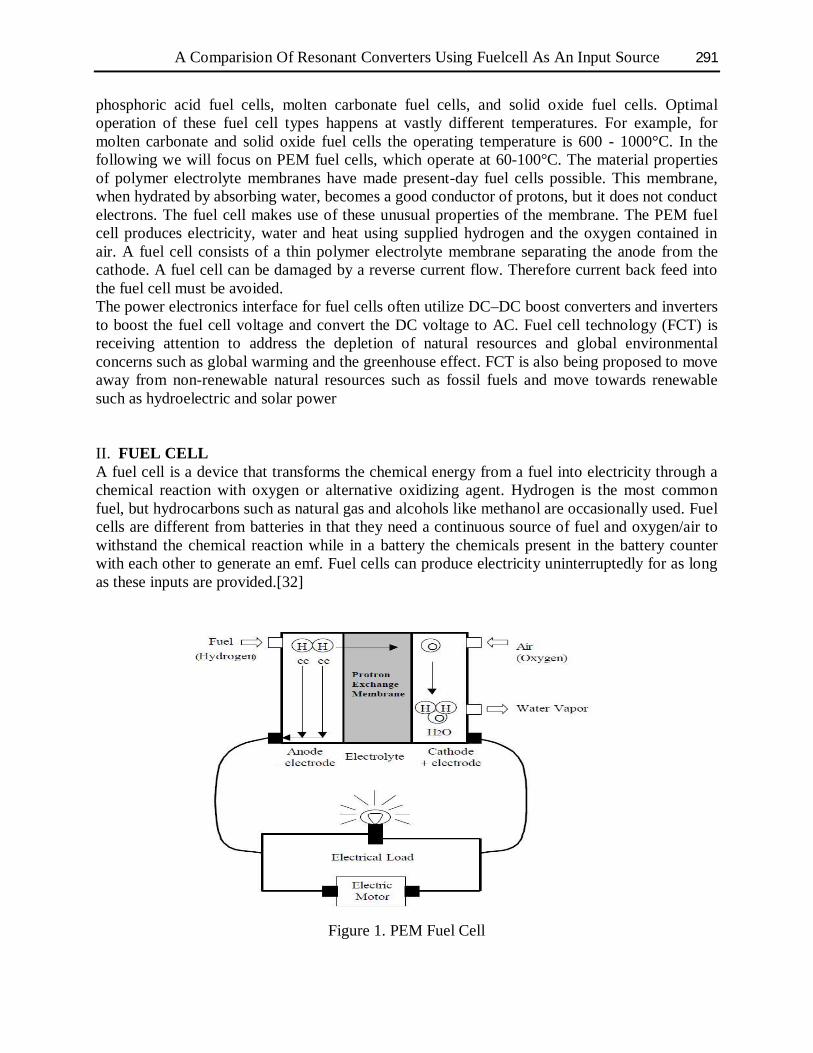
phosphoric acid fuel cells, molten carbonate fuel cells, and solid oxide fuel cells. Optimal operation of these fuel cell types happens at vastly different temperatures. For example, for molten carbonate and solid oxide fuel cells the operating temperature is 600 - 1000°C. In the following we will focus on PEM fuel cells, which operate at 60-100°C. The material properties of polymer electrolyte membranes have made present-day fuel cells possible. This membrane, when hydrated by absorbing water, becomes a good conductor of protons, but it does not conduct electrons. The fuel cell makes use of these unusual properties of the membrane. The PEM fuel cell produces electricity, water and heat using supplied hydrogen and the oxygen contained in air. A fuel cell consists of a thin polymer electrolyte membrane separating the anode from the cathode. A fuel cell can be damaged by a reverse current flow. Therefore current back feed into the fuel cell must be avoided. The power electronics interface for fuel cells often utilize DC–DC boost converters and inverters to boost the fuel cell voltage and convert the DC voltage to AC. Fuel cell technology (FCT) is receiving attention to address the depletion of natural resources and global environmental concerns such as global warming and the greenhouse effect. FCT is also being proposed to move away from non-renewable natural resources such as fossil fuels and move towards renewable such as hydroelectric and solar power II. FUEL CELL A fuel cell is a device that transforms the chemical energy from a fuel into electricity through a chemical reaction with oxygen or alternative oxidizing agent. Hydrogen is the most common fuel, but hydrocarbons such as natural gas and alcohols like methanol are occasionally used. Fuel cells are different from batteries in that they need a continuous source of fuel and oxygen/air to withstand the chemical reaction while in a battery the chemicals present in the battery counter with each other to generate an emf. Fuel cells can produce electricity uninterruptedly for as long as these inputs are provided.[32]
Figure 1. PEM Fuel Cell
Author Name 292
Hydrogen comes into the anode side of the fuel cell. At the same time Oxygen is applied to the cathode side. The hydrogen protons pass over PEM (Proton Exchange Membrane) while the electrons of the hydrogen cannot pierce the membrane. The PEM is the electrolyte that permits the protons but not the electrons. The electrons looking for the least path of resistance will flow from the anode of the fuel cell over an electrical circuit to power electrical devices or loads and coming back to the fuel cell via the cathode. The electrons will join with the hydrogen and oxygen within the cell to form a water molecule which is the water vapour by product of the fuel cell. In actuality billions of water molecules are formed. This speedy combination of elements also generates heat. A PEM fuel cell has an ordinary operating temperature of 80 degrees C or 176 degrees F. The merging of hydrogen and oxygen elements produces free electrons which is the preferred energy output. i.e. Electricity. 2.1 Principle of working A Fuel cell is an energy conversion device that converts the chemical energy of a reaction into electricity with by-product of water and heat. The fuel cell consists of an electrolyte layer in contact with two electrodes on both side. The hydrogen fuel is fed constantly to anode electrode and oxidant (or) oxygen from the air is fed constantly to the cathode electrode. At the anode terminal hydrogen fuel is disintegrated into positive ions and negative ions. The intermediary electrolyte membrane permits only the positive ions to flow from anode to cathode side and acts as an insulator for electrons. These electrons want to recombine on the other side of the membrane for the structure to become stable for which the few electrons moved through the cathode side through an outward electrical circuit. The recombination of positive and negative ions with oxidant takes place at the cathode to form exhausted oxidant or pure water. The chemical reactions involved in the anode and cathode and its overall reactions are as given as below: Anode Reaction: H2 → 2H+ + 2e_ (1)
Cathode Reaction: 1/2O2 + 2H+ + 2e_ → H2O (2)
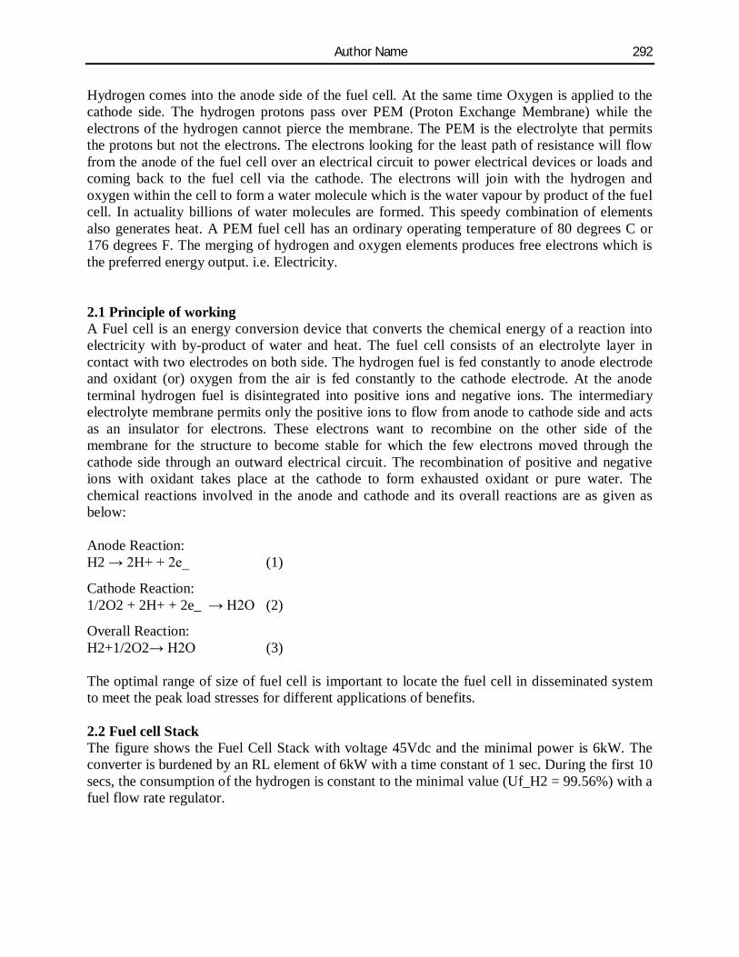
Overall Reaction: H2+1/2O2→ H2O (3) The optimal range of size of fuel cell is important to locate the fuel cell in disseminated system to meet the peak load stresses for different applications of benefits. 2.2 Fuel cell Stack The figure shows the Fuel Cell Stack with voltage 45Vdc and the minimal power is 6kW. The converter is burdened by an RL element of 6kW with a time constant of 1 sec. During the first 10 secs, the consumption of the hydrogen is constant to the minimal value (Uf_H2 = 99.56%) with a fuel flow rate regulator.
A Comparision Of Resonant Converters Using Fuelcell As An Input Source 293
Figure 2. A 6 KW,45V DC Fuel cell Stack After 10 secs, the flow rate regulator is bypassed and the rate of fuel is increased to the maximum value of 85 lpm in order to observe the discrepancy in the stack voltage. That will disturb the stack efficiency, the fuel intake and the air intake. Fuel cell voltage, current, DC/DC converter voltage and DC/DC converter current signals are obtainable on the Scope2. Fuel flow rate, Hydrogen and oxygen use, fuel and air intake, and efficiency are obtainable on the Scope1. At t = 0 s, the DC/DC converter applies 100Vdc to the RL load (the initial current of the load is 0A). The fuel consumption is set to the nominal value of 99.56%. The current increases to the value of 133A. The flow rate is repeatedly set in order to maintain the nominal fuel application. Observe the DC bus voltage (Scope2) which is very well controlled by the converter. The peak voltage of 122Vdc at the commencement of the simulation is caused by the short-lived state of the voltage regulator. At t = 10 s, the fuel flow rate is increased from 50 liters per minute (lpm) to 85 lpm during 3.5 s reducing by doing so the hydrogen consumption. This causes an increasing of the Nernst voltage so the fuel cell current will decrease. Hence the stack intake and the efficiency will decrease (Scope1). III. CONVENTIONAL PWM CONVERTERS AND RESONANT MODE CONVERTERS Conventional PWM converters are the most common power supplies in existing power electronic marketplace. The PWM controllers from several venders are extensively offered for power designer. The traditional PWM isolated converterconsists of an inverter, isolation transformer, output rectifier and output low pass filter. The DC input voltage is chopped at a high frequency to create square wave AC voltage. This AC voltage can be upraised and lowered with transformer, and then it can be rectified and filtered to get a DC output voltage as per requirement. The duty cycle of square wave regulates the amplitude of output voltage. And it can be varied to regulate the voltage against input voltage dissimilarity. In resonant mode converter, taking adjustable frequency control resonant converter as an example, it works in a different way. The DC input voltage is given to high frequency inverter, chopped into AC square wave. The AC voltage then is determined into a resonant tank which
Author Name 294
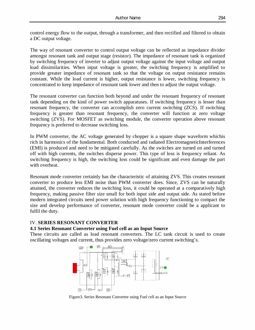
control energy flow to the output, through a transformer, and then rectified and filtered to obtain a DC output voltage. The way of resonant converter to control output voltage can be reflected as impedance divider amongst resonant tank and output stage (resistor). The impedance of resonant tank is organized by switching frequency of inverter to adjust output voltage against the input voltage and output load dissimilarities. When input voltage is greater, the switching frequency is amplified to provide greater impedance of resonant tank so that the voltage on output resistance remains constant. While the load current is higher, output resistance is lower, switching frequency is concentrated to keep impedance of resonant tank lower and then to adjust the output voltage. The resonant converter can function both beyond and under the resonant frequency of resonant tank depending on the kind of power switch apparatuses. If switching frequency is lesser than resonant frequency, the converter can accomplish zero current switching (ZCS). If switching frequency is greater than resonant frequency, the converter will function at zero voltage switching (ZVS). For MOSFET as switching module, the converter operation above resonant frequency is preferred to decrease switching loss. In PWM converter, the AC voltage generated by chopper is a square shape waveform whichis rich in harmonics of the fundamental. Both conducted and radiated ElectromagneticInterferences (EMI) is produced and need to be mitigated carefully. As the switches are turned on and turned off with high currents, the switches disperse power. This type of loss is frequency reliant. As switching frequency is high, the switching loss could be significant and even damage the part with overheat. Resonant mode converter certainly has the characteristic of attaining ZVS. This creates resonant converter to produce less EMI noise than PWM converter does. Since, ZVS can be naturally attained, the converter reduces the switching loss, it could be operated at a comparatively high frequency, making passive filter size small for both input side and output side. As stated before modern integrated circuits need power solution with high frequency functioning to compact the size and develop performance of converter, resonant mode converter could be a applicant to fulfil the duty. IV. SERIES RESONANT CONVERTER 4.1 Series Resonant Converter using Fuel cell as an Input Source These circuits are called as load resonant converters. The LC tank circuit is used to create oscillating voltages and current, thus provides zero voltage/zero current switching’s.
Figure3. Series Resonant Converter using Fuel cell as an Input Source
A Comparision Of Resonant Converters Using Fuelcell As An Input Source 295
In series resonant converters, the load is connected in series with the series L-C circuit through a transformer. The transformer ac output is then rectified to get the desired dc voltage. The output voltage can be controlled by controlling the frequency thereby controlling the L-C tank circuit current on resonance characteristics. The disadvantage of series resonant converter is output capacitor has to transmit high ripple
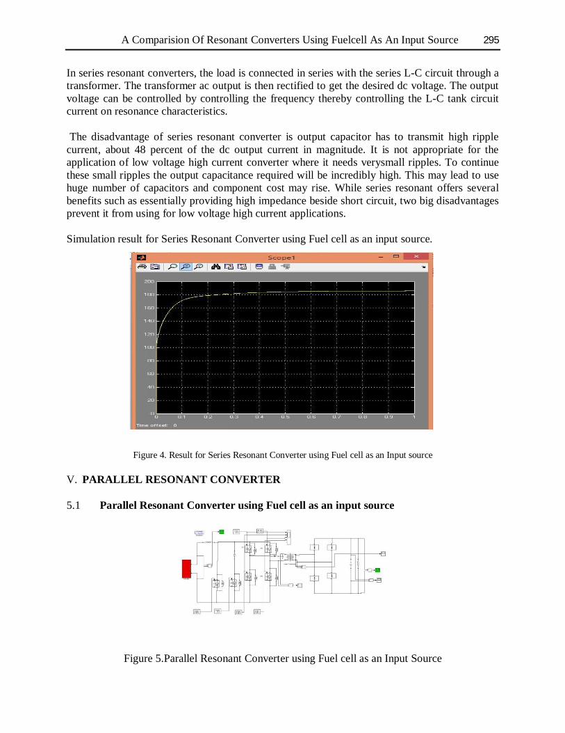
current, about 48 percent of the dc output current in magnitude. It is not appropriate for the application of low voltage high current converter where it needs verysmall ripples. To continue these small ripples the output capacitance required will be incredibly high. This may lead to use huge number of capacitors and component cost may rise. While series resonant offers several benefits such as essentially providing high impedance beside short circuit, two big disadvantages prevent it from using for low voltage high current applications. Simulation result for Series Resonant Converter using Fuel cell as an input source.
Figure 4. Result for Series Resonant Converter using Fuel cell as an Input source V. PARALLEL RESONANT CONVERTER 5.1 Parallel Resonant Converter using Fuel cell as an input source
Figure 5.Parallel Resonant Converter using Fuel cell as an Input Source
Author Name 296
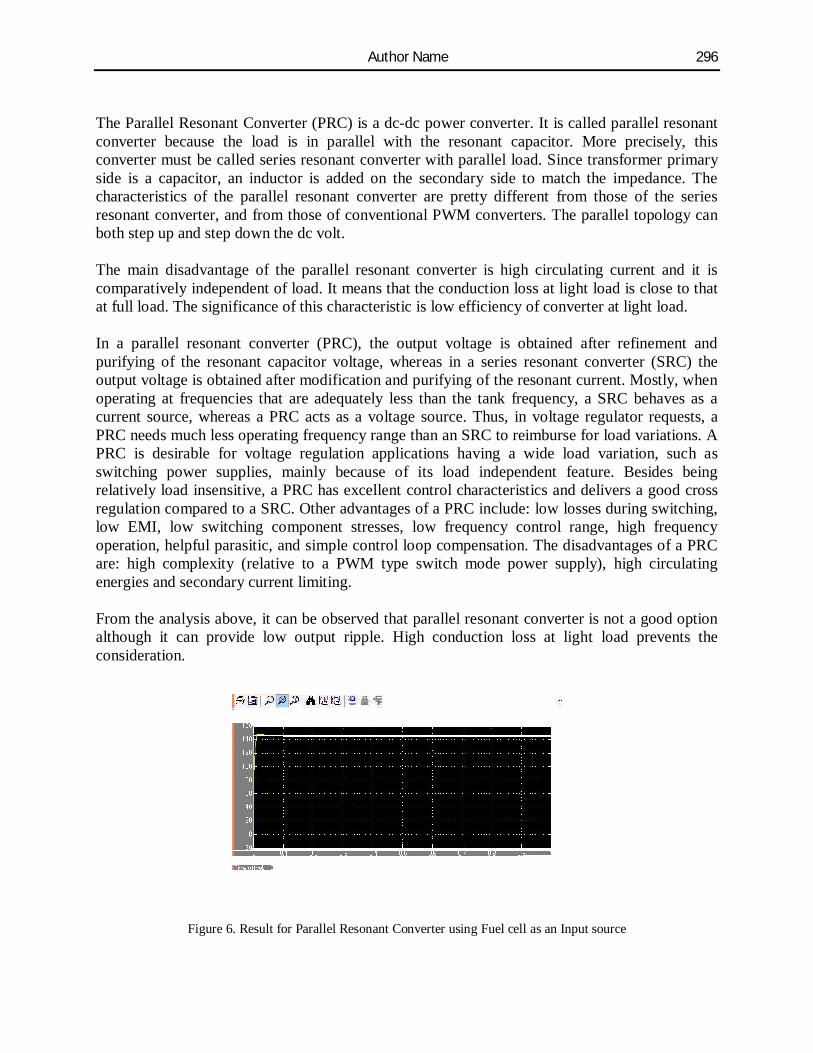
The Parallel Resonant Converter (PRC) is a dc-dc power converter. It is called parallel resonant converter because the load is in parallel with the resonant capacitor. More precisely, this converter must be called series resonant converter with parallel load. Since transformer primary side is a capacitor, an inductor is added on the secondary side to match the impedance. The characteristics of the parallel resonant converter are pretty different from those of the series resonant converter, and from those of conventional PWM converters. The parallel topology can both step up and step down the dc volt. The main disadvantage of the parallel resonant converter is high circulating current and it is comparatively independent of load. It means that the conduction loss at light load is close to that at full load. The significance of this characteristic is low efficiency of converter at light load. In a parallel resonant converter (PRC), the output voltage is obtained after refinement and purifying of the resonant capacitor voltage, whereas in a series resonant converter (SRC) the output voltage is obtained after modification and purifying of the resonant current. Mostly, when operating at frequencies that are adequately less than the tank frequency, a SRC behaves as a current source, whereas a PRC acts as a voltage source. Thus, in voltage regulator requests, a PRC needs much less operating frequency range than an SRC to reimburse for load variations. A PRC is desirable for voltage regulation applications having a wide load variation, such as switching power supplies, mainly because of its load independent feature. Besides being relatively load insensitive, a PRC has excellent control characteristics and delivers a good cross regulation compared to a SRC. Other advantages of a PRC include: low losses during switching, low EMI, low switching component stresses, low frequency control range, high frequency operation, helpful parasitic, and simple control loop compensation. The disadvantages of a PRC are: high complexity (relative to a PWM type switch mode power supply), high circulating energies and secondary current limiting. From the analysis above, it can be observed that parallel resonant converter is not a good option although it can provide low output ripple. High conduction loss at light load prevents the consideration.
Figure 6. Result for Parallel Resonant Converter using Fuel cell as an Input source
A Comparision Of Resonant Converters Using Fuelcell As An Input Source 297
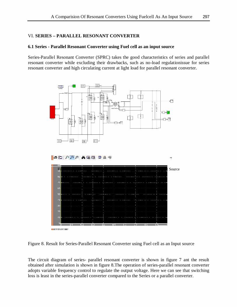
VI. SERIES – PARALLEL RESONANT CONVERTER 6.1 Series - Parallel Resonant Converter using Fuel cell as an input source Series-Parallel Resonant Converter (SPRC) takes the good characteristics of series and parallel resonant converter while excluding their drawbacks, such as no-load regulationissue for series resonant converter and high circulating current at light load for parallel resonant converter.
Figure 7.Series-Parallel Resonant Converter using Fuel cell as an Input Source Figure 8. Result for Series-Parallel Resonant Converter using Fuel cell as an Input source The circuit diagram of series- parallel resonant converter is shown in figure 7 ant the result obtained after simulation is shown in figure 8.The operation of series-parallel resonant converter adopts variable frequency control to regulate the output voltage. Here we can see that switching loss is least in the series-parallel converter compared to the Series or a parallel converter.
Author Name 298
VII. CONCLUSION This paper proposes a new technique of designing Series Resonant Converter, Parallel Resonant Converter and Series-Parallel Resonant Converter using Fuel cell as an Input source.As in PWM converter, the AC voltage created by chopper is a square shape waveform which is rich in harmonics of the fundamental. Both conducted and radiated Electromagnetic Interferences (EMI) is generated and need to be mitigated carefully. As the switches are turned on and turned off with high currents, the switches dissipate power. This type of loss is frequency dependent. As switching frequency is high, the switching loss could be significant and even damage the part with overheat. A comparative study is done on all the three types of converter and as shown in the results it is found that Series-Parallel type of converter can maintain soft switching with less switching losses. REFERENCES [1] Deepak S. Gautam, Ashoka K. S. Bhat, “A Comparison of Soft-Switched DC-to-DCConverters for
Electrolyzer Application”, Proceedings of lntemational the IEEE on power Electronics, vol. 28, no. 1, pp: 54-63 ,January 2013
[2] MilanaTrifkovic, Mehdi Sheikhzadeh, Khaled Nigim and ProdromosDaoutidis, “Modeling and Control of a Renewable Hybrid Energy System With Hydrogen Storage”, Proceedings of lntemational the IEEE on control systems technology, vol. 22, no. 1,pp: 169-179 January 2014
[3] Riccardo Pittini, Zhe Zhang, Michael A.E. Andersen, “Isolated Full Bridge Boost DC-DC Converter Designed for Bidirectional Operation of Fuel Cells/Electrolyzer Cells in Grid-Tie Applications: Technical university of Denmark , Department of Electrical Engineering
[8] Ali Elrayyah, Ali Safayet, Yilmaz Sozer and Malik Elbuluk , “Efficient harmonic and phase estimator for single-phase grid connected renewable energy systems”, Proceedings of IEEE transactions on industry applications, vol. 50, no. 1, January/February 2014 pp: 620-630
[9] Juan M. Galvez, Martin Ordonez, “Swinging Bus Operation of Inverters for Fuel Cell Applications with Small DC-Link Capacitance”,. Proceedings of IEEE transactions on Power Electronics, 2013
[11] Rui Yang, HongFa Ding, Yun Xu, Lei Yao, and YingMeng Xiang, “An Analytical Steady-State Model of LCC typeSeries–Parallel Resonant Converter With Capacitive Output Filter”, Proceedings of IEEE transactions on Power Electronics, vol. 29, no 1, pp: 328-338, Jan 2014
[12] FarhadPothukattil, Tiju Baby and Prabakaran M , “Isolated dual input dc-dc converter with ZVS for hybrid energy system applications”, Proceedings of International Conference on Advances in Energy Conversion Technologies (ICAECT), pp: 237-240, 2014
[13] Luca Corradini, Daniel Seltzer, Douglas Bloomquist, Regan Zane, DraganMaksimovi´c and Boris Jacobson “Zero voltage switching technique for bidirectional DC/Dc converters”, Proceedings of IEEE transactions on
A Comparision Of Resonant Converters Using Fuelcell As An Input Source 299
power electronics, vol. 29, no. 4, April 2014, pp: 1585-1594. [14] Hector Sarnago, Oscar Lucıa, Arturo Mediano and Jose M. Burdıo, “Direct AC–AC Resonant Boost
Converter for Efficient Domestic Induction Heating Applications,” Proceedings of IEEE transactions on power electronics, vol. 29, no. 3,March 2014, pp: 1128-1139
[15] Xiaodong Li, “A LLC-Type Dual-Bridge Resonant Converter, Analysis, Design, Simulation, and Experimental Results,” Proceedings of IEEE transactions on power electronics, vol. 29, no. 8, August 2014, pp: 4313-4321
[16] Xiaohu Liu, Hui Li, and Zhan Wang, “A Fuel Cell Power Conditioning System With Low- Frequency Ripple-Free Input Current Using a Control-Oriented Power Pulsation Decoupling Strategy,” Proceedings of IEEE transactions on Power Electronics, vol. 29, no. 1, January 2014, pp: 159-169
[17] Minsoo Jang and Vassilios G. Agelidis, “A Boost-Inverter Based Battery-Supported Fuel-Cell Sourced Three-Phase Stand-Alone Power Supply,” Proceedings of IEEE transactions on Power Electronics, Feb 2012
[18] Shu-Kong Ki and Dylan Dah-Chuan Lu, “A High Step-Down Transformer less Single-Stage Single Switch AC/DC Converter,” Proceedings of IEEE transactions on Power Electronics, Vol.28, No.1,Jan 2013, pp:36-44
[19] Sayed Ali Khajehoddin, MasoudKarimi-Ghartemani, AlirezaBakhshai and Praveen Jain, “A Power Control Method With Simple Structure and Fast Dynamic Response for Single-Phase Grid-Connected DG Systems” Proceedings of IEEE transactions on Power Electronics, Vol.28, No.1,Jan 2013, pp:221-233
[20] R.Samuel Rajesh Babu and Joseph Henry, “A Comparative Analysis of DC-DC Converters for Renewable Energy System” Proceedings of the international Multi conference of Engineers & Computer Scientists IMECS March 2012, Vol II