Page 1
A comparison of IP vs 3G Network
Performance Indicators
Jan Venter
A research report submitted to the Faculty of Engineering and the Built
Environment, University of the Witwatersrand, Johannesburg, in partial
fulfilment of the requirements for the degree of Master of Science in
Engineering.
Johannesburg, 2011
Page 3
Declaration
I declare that this research report is my own unaided work. It is being submitted to the Degree
of Master of Science to the University of the Witwatersrand, Johannesburg. It has not been
submitted before for any degree or examination to any other University.
. . . . . . . . . . . . . . . . . . . . . . .
(Signature of candidate)
. . . . . . . . . day of . . . . . . . . . . . . . . . year . . . . . . . . .
day month year
iii
Page 5
Abstract
Telecommunication networks of mobile operators are evolving to use an underlying packet-
based IP (Internet Protocol) network using Multi Protocol Label Switching (MPLS) as their
core technology. The key performance indicators (KPIs) for monitoring the performance of the
3G mobile network’s voice and data services are well established, as are the key performance
indicators for interfaces and nodes on an IP network.
For this research report an investigation was done on the correlation between the IP KPIs
and 3G KPIs through analysis of packet level traces to obtain the IP KPIs as well as reports
on KPIs collected on the nodes of the 3G data network. The study was done on MTN South
Africa’s operational network at two sites for 2 observation periods of 30 days, with specific focus
on the busy hour performance. In addition to the well-known IP KPIs, two extra measurements
that were found during a literature survey (SRTO - Spurious Retransmission Timeout and ISR
- Invalid Sample Ratio) were calculated based on the packet level traces of IP traffic. The 3G
KPIs were chosen from industry standard network quality benchmark reports.
The correlation study found no strong linear relationships between the sets of IP and 3G
KPIs. This was due to certain limitations in the experimental setup and the observed behaviour
of the network (few instances of degradation of behaviour). Further study with modifications to
the experimental setup and packet-trace analysis and possibly artificial introduction of negative
network conditions will be necessary to verify if correlations exist between the IP and 3G KPIs.
v
Page 6
To my wife Linde and our daughters Lida and Klara.
Page 7
Acknowledgements
I’d like to acknowledge MTN South Africa for the partial study bursaries that they awarded me
to complete this research, as well as allowing me to make use of monitoring equipment essential
for this research. I’d also like to acknowledge my manager at MTN, Mr. Ben Wolmarans for
his willingness to allow me a flexible work schedule in order to attend class and do this research.
vii
Page 9
Contents
Contents i
List of Figures v
List of Tables ix
List of Symbols and Abbreviations xi
1 Introduction 1
1.1 Background . . . . . . . . . . . . . . . . . . . . . . . . . . . . . . . . . . . . 1
1.2 Objective . . . . . . . . . . . . . . . . . . . . . . . . . . . . . . . . . . . . . 2
1.2.1 Sub questions . . . . . . . . . . . . . . . . . . . . . . . . . . . . . . . 2
1.3 Scope of work . . . . . . . . . . . . . . . . . . . . . . . . . . . . . . . . . . . 2
1.4 Method . . . . . . . . . . . . . . . . . . . . . . . . . . . . . . . . . . . . . . 3
2 Literature survey 5
2.1 IP Performance metrics . . . . . . . . . . . . . . . . . . . . . . . . . . . . . 5
2.1.1 Throughput . . . . . . . . . . . . . . . . . . . . . . . . . . . . . . . . 5
2.1.2 Packet Loss . . . . . . . . . . . . . . . . . . . . . . . . . . . . . . . . 6
2.1.3 Packet Delay . . . . . . . . . . . . . . . . . . . . . . . . . . . . . . . 6
2.1.4 Packet Delay Variation(jitter) . . . . . . . . . . . . . . . . . . . . . . 7
2.2 3G Packet data network background . . . . . . . . . . . . . . . . . . . . . . 7
2.2.1 UE - User Equipment . . . . . . . . . . . . . . . . . . . . . . . . . . 7
2.2.2 NodeB . . . . . . . . . . . . . . . . . . . . . . . . . . . . . . . . . . . 8
2.2.3 RNC - Radio Network Controller . . . . . . . . . . . . . . . . . . . . 8
2.2.4 SGSN - Serving GPRS Support Node . . . . . . . . . . . . . . . . . 8
2.2.5 GGSN - Gateway GPRS Support Node . . . . . . . . . . . . . . . . 8
2.2.6 CG - Charging Gateway . . . . . . . . . . . . . . . . . . . . . . . . . 8
2.2.7 HLR - Home Location Register . . . . . . . . . . . . . . . . . . . . . 8
2.2.8 EIR - Equipment Identity Register . . . . . . . . . . . . . . . . . . . 9
2.2.9 AuC - Authentication Centre . . . . . . . . . . . . . . . . . . . . . . 9
2.2.10 DNS - Domain Name Server . . . . . . . . . . . . . . . . . . . . . . . 9
2.2.11 BG - Border Gateway . . . . . . . . . . . . . . . . . . . . . . . . . . 9
2.2.12 Internet DNS . . . . . . . . . . . . . . . . . . . . . . . . . . . . . . . 9
2.2.13 AAA server . . . . . . . . . . . . . . . . . . . . . . . . . . . . . . . . 10
2.3 3G KPIs . . . . . . . . . . . . . . . . . . . . . . . . . . . . . . . . . . . . . . 10
i
Page 10
ii CONTENTS
2.3.1 NetQB reports - Network Quality Benchmark . . . . . . . . . . . . . 10
2.3.2 Attach Failure Rate . . . . . . . . . . . . . . . . . . . . . . . . . . . 10
2.3.3 Attach Failure Rate due to congestion . . . . . . . . . . . . . . . . . 11
2.3.4 Intra SGSN RAU Success Rate . . . . . . . . . . . . . . . . . . . . . 11
2.3.5 Inter SGSN RAU Success Rate . . . . . . . . . . . . . . . . . . . . . 12
2.3.6 PS Paging Failure Rate . . . . . . . . . . . . . . . . . . . . . . . . . 12
2.3.7 PDP Context Activation Failure Rate . . . . . . . . . . . . . . . . . 12
2.3.8 PDP Activation Failure rate due to lack of resources . . . . . . . . . 13
2.3.9 Average throughput per user . . . . . . . . . . . . . . . . . . . . . . 14
2.4 Statistics for correlation study . . . . . . . . . . . . . . . . . . . . . . . . . . 14
2.4.1 Sample correlation coefficient . . . . . . . . . . . . . . . . . . . . . . 14
2.5 Recent studies on 3G and IP network performance . . . . . . . . . . . . . . 16
2.5.1 Related work . . . . . . . . . . . . . . . . . . . . . . . . . . . . . . . 18
2.6 Summary . . . . . . . . . . . . . . . . . . . . . . . . . . . . . . . . . . . . . 18
3 Key research question 21
3.1 Review of problem . . . . . . . . . . . . . . . . . . . . . . . . . . . . . . . . 21
3.2 Objective . . . . . . . . . . . . . . . . . . . . . . . . . . . . . . . . . . . . . 22
3.2.1 Research details . . . . . . . . . . . . . . . . . . . . . . . . . . . . . 22
3.3 Expected results . . . . . . . . . . . . . . . . . . . . . . . . . . . . . . . . . 23
3.3.1 Expected results for Gn interface . . . . . . . . . . . . . . . . . . . . 23
3.3.2 Expected results for Gi interface . . . . . . . . . . . . . . . . . . . . 23
3.4 Summary . . . . . . . . . . . . . . . . . . . . . . . . . . . . . . . . . . . . . 23
4 Methodology 25
4.1 IP KPIs . . . . . . . . . . . . . . . . . . . . . . . . . . . . . . . . . . . . . . 25
4.1.1 Process . . . . . . . . . . . . . . . . . . . . . . . . . . . . . . . . . . 26
4.1.2 Trace gathering . . . . . . . . . . . . . . . . . . . . . . . . . . . . . . 26
4.1.3 Calculation of Throughput . . . . . . . . . . . . . . . . . . . . . . . 27
4.1.4 Calculation of Packet Delay . . . . . . . . . . . . . . . . . . . . . . . 30
4.1.5 Calculation of Jitter . . . . . . . . . . . . . . . . . . . . . . . . . . . 32
4.1.6 Calculation of ISR . . . . . . . . . . . . . . . . . . . . . . . . . . . . 34
4.1.7 Calculation of SRTO . . . . . . . . . . . . . . . . . . . . . . . . . . . 37
4.2 3G KPIs . . . . . . . . . . . . . . . . . . . . . . . . . . . . . . . . . . . . . . 39
4.2.1 SGSN statistics collection . . . . . . . . . . . . . . . . . . . . . . . . 39
4.2.2 GGSN statistics collection . . . . . . . . . . . . . . . . . . . . . . . . 40
4.2.3 KPI reports . . . . . . . . . . . . . . . . . . . . . . . . . . . . . . . . 40
4.2.4 Attach Failure Rate . . . . . . . . . . . . . . . . . . . . . . . . . . . 41
4.2.5 Inter SGSN RAU Success Rate . . . . . . . . . . . . . . . . . . . . . 43
4.2.6 PDP Cutoff Ratio . . . . . . . . . . . . . . . . . . . . . . . . . . . . 45
4.2.7 PDP Activation Success Rate . . . . . . . . . . . . . . . . . . . . . . 45
4.2.8 Average throughput per user . . . . . . . . . . . . . . . . . . . . . . 47
4.3 Summary . . . . . . . . . . . . . . . . . . . . . . . . . . . . . . . . . . . . . 47
5 Experimental results 49
5.1 IP KPIs over time . . . . . . . . . . . . . . . . . . . . . . . . . . . . . . . . 50
5.1.1 Throughput . . . . . . . . . . . . . . . . . . . . . . . . . . . . . . . . 50
5.1.2 Packet delay - Round trip time . . . . . . . . . . . . . . . . . . . . . 51
Page 11
CONTENTS iii
5.1.3 Jitter . . . . . . . . . . . . . . . . . . . . . . . . . . . . . . . . . . . 53
5.1.4 ISR . . . . . . . . . . . . . . . . . . . . . . . . . . . . . . . . . . . . 54
5.1.5 SRTO . . . . . . . . . . . . . . . . . . . . . . . . . . . . . . . . . . . 55
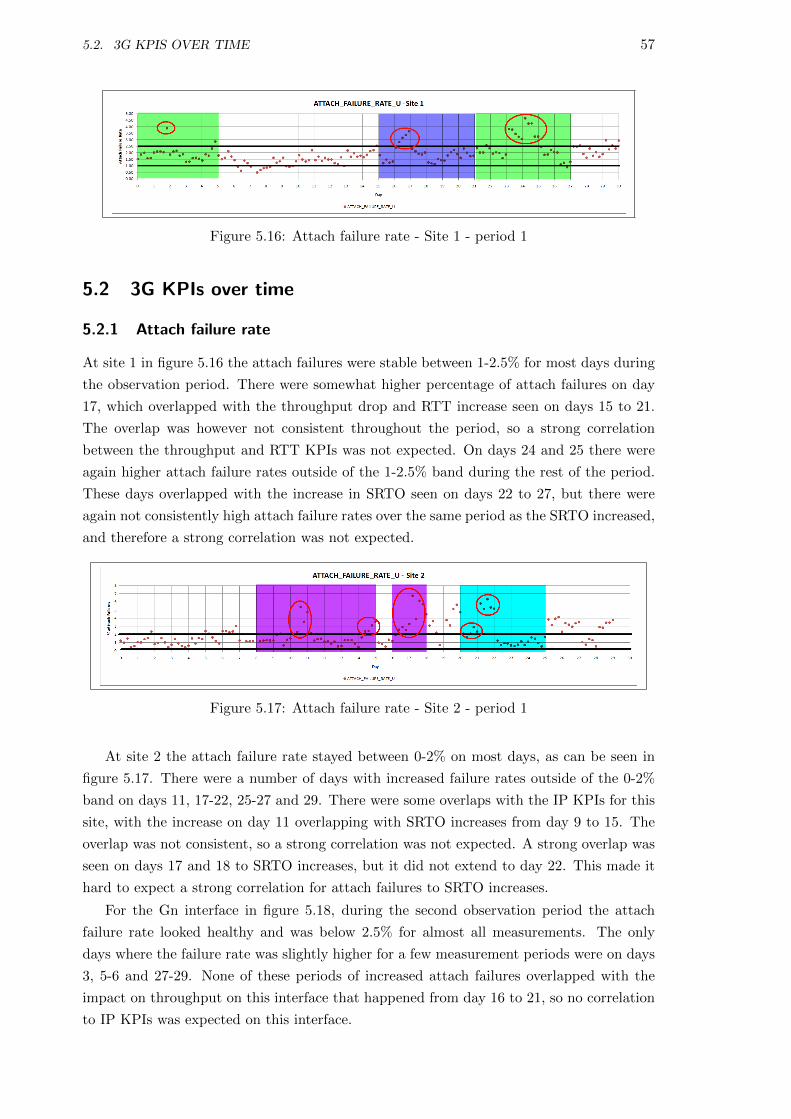
5.2 3G KPIs over time . . . . . . . . . . . . . . . . . . . . . . . . . . . . . . . . 57
5.2.1 Attach failure rate . . . . . . . . . . . . . . . . . . . . . . . . . . . . 57
5.2.2 InterRAU Success Rate . . . . . . . . . . . . . . . . . . . . . . . . . 58
5.2.3 PDP Cutoff Ratio . . . . . . . . . . . . . . . . . . . . . . . . . . . . 59
5.2.4 PDP Activation Success Rate . . . . . . . . . . . . . . . . . . . . . . 61
5.2.5 Average throughput per subscriber . . . . . . . . . . . . . . . . . . . 62
5.3 Correlation study . . . . . . . . . . . . . . . . . . . . . . . . . . . . . . . . . 63
5.3.1 PDP Activation to ISR correlation - example 1 . . . . . . . . . . . . 64
5.3.2 PDP Activation to ISR correlation - example 2 . . . . . . . . . . . . 65
5.3.3 Average Throughput to SRTO correlation - example 3 . . . . . . . . 65
5.4 Summary . . . . . . . . . . . . . . . . . . . . . . . . . . . . . . . . . . . . . 66
6 Conclusion 67
6.1 Results . . . . . . . . . . . . . . . . . . . . . . . . . . . . . . . . . . . . . . . 67
6.2 Conclusion . . . . . . . . . . . . . . . . . . . . . . . . . . . . . . . . . . . . 68
6.3 Future work . . . . . . . . . . . . . . . . . . . . . . . . . . . . . . . . . . . . 69
Bibliography 71
A Correlation scatter plots 77
A.1 Gi interface correlations . . . . . . . . . . . . . . . . . . . . . . . . . . . . . 77
A.1.1 Throughput to 3G KPIs . . . . . . . . . . . . . . . . . . . . . . . . . 77
A.1.2 RTT to 3G KPIs . . . . . . . . . . . . . . . . . . . . . . . . . . . . . 77
A.1.3 Jitter to 3G KPIs . . . . . . . . . . . . . . . . . . . . . . . . . . . . 78
A.1.4 ISR to 3G KPIs . . . . . . . . . . . . . . . . . . . . . . . . . . . . . 78
A.1.5 SRTO to 3G KPIs . . . . . . . . . . . . . . . . . . . . . . . . . . . . 78
A.2 Gn interface correlations . . . . . . . . . . . . . . . . . . . . . . . . . . . . . 78
A.2.1 Throughput to 3G KPIs . . . . . . . . . . . . . . . . . . . . . . . . . 78
A.2.2 RTT to 3G KPIs . . . . . . . . . . . . . . . . . . . . . . . . . . . . . 85
A.2.3 Jitter to 3G KPIs . . . . . . . . . . . . . . . . . . . . . . . . . . . . 86
A.2.4 ISR to 3G KPIs . . . . . . . . . . . . . . . . . . . . . . . . . . . . . 87
A.2.5 SRTO to 3G KPIs . . . . . . . . . . . . . . . . . . . . . . . . . . . . 88
B throughput.pl 89
C rtt.pl 93
D jitter.pl 99
E invalid sample ratio.pl 103
Page 13
List of Figures
2.1 3G Packet Network . . . . . . . . . . . . . . . . . . . . . . . . . . . . . . . . . . 7
2.2 PDP context activation . . . . . . . . . . . . . . . . . . . . . . . . . . . . . . . 13
2.3 Strong negative correlation, r = −0.98 . . . . . . . . . . . . . . . . . . . . . . . 15
2.4 No correlation, r = 0.01 . . . . . . . . . . . . . . . . . . . . . . . . . . . . . . . 15
2.5 Strong positive correlation, r = 0.98 . . . . . . . . . . . . . . . . . . . . . . . . 15
4.1 Packet capture scheme . . . . . . . . . . . . . . . . . . . . . . . . . . . . . . . . 26
4.2 Packet capture scheme . . . . . . . . . . . . . . . . . . . . . . . . . . . . . . . . 27
4.3 Throughput calculation from packet flow past observation point . . . . . . . . . 28
4.4 Flow diagram of throughput calculation algorithm . . . . . . . . . . . . . . . . 29
4.5 Round-trip-time (RTT) calculation from packet flow past observation point . . 30
4.6 Flow diagram of RTT calculation algorithm . . . . . . . . . . . . . . . . . . . . 31
4.7 Jitter calculation from packet flow past observation point . . . . . . . . . . . . 32
4.8 Flow diagram of Jitter calculation algorithm . . . . . . . . . . . . . . . . . . . 33
4.9 Invalid Sample Ratio (ISR) calculation from packet flow past observation point 34
4.10 Flow diagram of ISR calculation algorithm . . . . . . . . . . . . . . . . . . . . 36
4.11 Spurious Retransmission Timeout (SRTO) calculation from packet flow past
observation point . . . . . . . . . . . . . . . . . . . . . . . . . . . . . . . . . . . 38
4.12 SGSN statistics process flow . . . . . . . . . . . . . . . . . . . . . . . . . . . . . 39
4.13 GGSN statistics process flow . . . . . . . . . . . . . . . . . . . . . . . . . . . . 40
4.14 FACTS report example . . . . . . . . . . . . . . . . . . . . . . . . . . . . . . . 41
4.15 GPRS attach procedure in a 3G network . . . . . . . . . . . . . . . . . . . . . . 42
4.16 Attach failure calculation sets . . . . . . . . . . . . . . . . . . . . . . . . . . . . 42
4.17 Inter SGSN RAU procedure in a 3G network . . . . . . . . . . . . . . . . . . . 43
4.18 Inter SGSN RAU calculation sets . . . . . . . . . . . . . . . . . . . . . . . . . . 44
4.19 PDP Cutoff Ratio calculation sets . . . . . . . . . . . . . . . . . . . . . . . . . 45
4.20 PDP Activation procedure in a 3G network . . . . . . . . . . . . . . . . . . . . 46
4.21 PDP Context Activation calculation sets . . . . . . . . . . . . . . . . . . . . . . 47
5.1 Throughput - Gi site 1 - period 1 . . . . . . . . . . . . . . . . . . . . . . . . . . 50
5.2 Throughput - Gi site 2 - period 1 . . . . . . . . . . . . . . . . . . . . . . . . . . 51
5.3 Throughput - Gn site 1 - period 2 . . . . . . . . . . . . . . . . . . . . . . . . . 51
5.4 RTT - Gi site 1 - period 1 . . . . . . . . . . . . . . . . . . . . . . . . . . . . . . 52
5.5 RTT - Gi site 2 - period 1 . . . . . . . . . . . . . . . . . . . . . . . . . . . . . . 52
5.6 RTT - Gn site 1 - period 2 . . . . . . . . . . . . . . . . . . . . . . . . . . . . . 52
v
Page 14
vi LIST OF FIGURES
5.7 Jitter - Gi site 1 - period 1 . . . . . . . . . . . . . . . . . . . . . . . . . . . . . 53
5.8 Jitter - Gi site 2 - period 1 . . . . . . . . . . . . . . . . . . . . . . . . . . . . . 53
5.9 Jitter - Gn site 1 - period 2 . . . . . . . . . . . . . . . . . . . . . . . . . . . . . 54
5.10 ISR - Gi site 1 - period 1 . . . . . . . . . . . . . . . . . . . . . . . . . . . . . . 54
5.11 ISR - Gi site 2 - period 1 . . . . . . . . . . . . . . . . . . . . . . . . . . . . . . 55
5.12 ISR - Gn site 1 - period 2 . . . . . . . . . . . . . . . . . . . . . . . . . . . . . . 55
5.13 SRTO - Gi site 1 - period 1 . . . . . . . . . . . . . . . . . . . . . . . . . . . . . 55
5.14 SRTO - Gi site 2 - period 1 . . . . . . . . . . . . . . . . . . . . . . . . . . . . . 56
5.15 SRTO - Gn site 1 - period 2 . . . . . . . . . . . . . . . . . . . . . . . . . . . . . 56
5.16 Attach failure rate - Site 1 - period 1 . . . . . . . . . . . . . . . . . . . . . . . . 57
5.17 Attach failure rate - Site 2 - period 1 . . . . . . . . . . . . . . . . . . . . . . . . 57
5.18 Attach failure rate - Site 1 - period 2 . . . . . . . . . . . . . . . . . . . . . . . . 58
5.19 InterRAU Success Rate - Site 1 - period 1 . . . . . . . . . . . . . . . . . . . . . 58
5.20 InterRAU Success Rate - Site 2 - period 1 . . . . . . . . . . . . . . . . . . . . . 59
5.21 InterRAU Success Rate - Site 1 - period 2 . . . . . . . . . . . . . . . . . . . . . 59
5.22 PDP Cutoff Ratio - Site 1 - period 1 . . . . . . . . . . . . . . . . . . . . . . . . 59
5.23 PDP Cutoff Ratio - Site 2 - period 1 . . . . . . . . . . . . . . . . . . . . . . . . 60
5.24 PDP Cutoff Ratio - Site 1 - period 2 . . . . . . . . . . . . . . . . . . . . . . . . 60
5.25 PDP Activation Success Rate - Site 1 - period 1 . . . . . . . . . . . . . . . . . 61
5.26 PDP Activation Success Rate - Site 2 - period 1 . . . . . . . . . . . . . . . . . 61
5.27 PDP Activation Success Rate - Site 1 - period 2 . . . . . . . . . . . . . . . . . 62
5.28 Average throughput - Site 1 - period 1 . . . . . . . . . . . . . . . . . . . . . . . 62
5.29 Average throughput - Site 2 - period 1 . . . . . . . . . . . . . . . . . . . . . . . 63
5.30 Average throughput - Site 1 - period 2 . . . . . . . . . . . . . . . . . . . . . . . 63
5.31 ISR vs PDP Activation - Gi - site 1 . . . . . . . . . . . . . . . . . . . . . . . . 65
5.32 ISR vs PDP Activation - Gi - site 2 . . . . . . . . . . . . . . . . . . . . . . . . 65
5.33 SRTO vs Avg Throughput - Gn - site 1 . . . . . . . . . . . . . . . . . . . . . . 66
A.1 Throughput vs Attach Failure - Gi - site 1 . . . . . . . . . . . . . . . . . . . . . 79
A.2 Throughput vs Attach Failure - Gi - site 2 . . . . . . . . . . . . . . . . . . . . . 79
A.3 Throughput vs InterRAU - Gi - site 1 . . . . . . . . . . . . . . . . . . . . . . . 79
A.4 Throughput vs InterRAU - Gi - site 2 . . . . . . . . . . . . . . . . . . . . . . . 79
A.5 Throughput vs PDP Activation - Gi - site 1 . . . . . . . . . . . . . . . . . . . . 79
A.6 Throughput vs PDP Activation - Gi - site 2 . . . . . . . . . . . . . . . . . . . . 79
A.7 Throughput vs PDPCutoff - Gi - site 1 . . . . . . . . . . . . . . . . . . . . . . 79
A.8 Throughput vs PDPCutoff - Gi - site 2 . . . . . . . . . . . . . . . . . . . . . . 79
A.9 Throughput vs Avg Throughput - Gi - site 1 . . . . . . . . . . . . . . . . . . . 79
A.10 Throughput vs Avg Throughput - Gi - site 2 . . . . . . . . . . . . . . . . . . . 79
A.11 RTT vs Attach Failure - Gi - site 1 . . . . . . . . . . . . . . . . . . . . . . . . . 80
A.12 RTT vs Attach Failure - Gi - site 2 . . . . . . . . . . . . . . . . . . . . . . . . . 80
A.13 RTT vs InterRAU - Gi - site 1 . . . . . . . . . . . . . . . . . . . . . . . . . . . 80
A.14 RTT vs InterRAU - Gi - site 2 . . . . . . . . . . . . . . . . . . . . . . . . . . . 80
A.15 RTT vs PDP Activation - Gi - site 1 . . . . . . . . . . . . . . . . . . . . . . . . 80
A.16 RTT vs PDP Activation - Gi - site 2 . . . . . . . . . . . . . . . . . . . . . . . . 80
A.17 RTT vs PDPCutoff - Gi - site 1 . . . . . . . . . . . . . . . . . . . . . . . . . . . 80
A.18 RTT vs PDPCutoff - Gi - site 2 . . . . . . . . . . . . . . . . . . . . . . . . . . . 80
A.19 RTT vs Avg Throughput - Gi - site 1 . . . . . . . . . . . . . . . . . . . . . . . 80
Page 15
LIST OF FIGURES vii
A.20 RTT vs Avg Throughput - Gi - site 2 . . . . . . . . . . . . . . . . . . . . . . . 80
A.21 Jitter vs Attach Failure - Gi - site 1 . . . . . . . . . . . . . . . . . . . . . . . . 81
A.22 Jitter vs Attach Failure - Gi - site 2 . . . . . . . . . . . . . . . . . . . . . . . . 81
A.23 Jitter vs InterRAU - Gi - site 1 . . . . . . . . . . . . . . . . . . . . . . . . . . . 81
A.24 Jitter vs InterRAU - Gi - site 2 . . . . . . . . . . . . . . . . . . . . . . . . . . . 81
A.25 Jitter vs PDP Activation - Gi - site 1 . . . . . . . . . . . . . . . . . . . . . . . 81
A.26 Jitter vs PDP Activation - Gi - site 2 . . . . . . . . . . . . . . . . . . . . . . . 81
A.27 Jitter vs PDPCutoff - Gi - site 1 . . . . . . . . . . . . . . . . . . . . . . . . . . 81
A.28 Jitter vs PDPCutoff - Gi - site 2 . . . . . . . . . . . . . . . . . . . . . . . . . . 81
A.29 Jitter vs Avg Throughput - Gi - site 1 . . . . . . . . . . . . . . . . . . . . . . . 81
A.30 Jitter vs Avg Throughput - Gi - site 2 . . . . . . . . . . . . . . . . . . . . . . . 81
A.31 ISR vs Attach Failure - Gi - site 1 . . . . . . . . . . . . . . . . . . . . . . . . . 82
A.32 ISR vs Attach Failure - Gi - site 2 . . . . . . . . . . . . . . . . . . . . . . . . . 82
A.33 ISR vs InterRAU - Gi - site 1 . . . . . . . . . . . . . . . . . . . . . . . . . . . . 82
A.34 ISR vs InterRAU - Gi - site 2 . . . . . . . . . . . . . . . . . . . . . . . . . . . . 82
A.35 ISR vs PDP Activation - Gi - site 1 . . . . . . . . . . . . . . . . . . . . . . . . 82
A.36 ISR vs PDP Activation - Gi - site 2 . . . . . . . . . . . . . . . . . . . . . . . . 82
A.37 ISR vs PDPCutoff - Gi - site 1 . . . . . . . . . . . . . . . . . . . . . . . . . . . 82
A.38 ISR vs PDPCutoff - Gi - site 2 . . . . . . . . . . . . . . . . . . . . . . . . . . . 82
A.39 ISR vs Avg Throughput - Gi - site 1 . . . . . . . . . . . . . . . . . . . . . . . . 82
A.40 ISR vs Avg Throughput - Gi - site 2 . . . . . . . . . . . . . . . . . . . . . . . . 82
A.41 SRTO vs Attach Failure - Gi - site 1 . . . . . . . . . . . . . . . . . . . . . . . . 83
A.42 SRTO vs Attach Failure - Gi - site 2 . . . . . . . . . . . . . . . . . . . . . . . . 83
A.43 SRTO vs InterRAU - Gi - site 1 . . . . . . . . . . . . . . . . . . . . . . . . . . . 83
A.44 SRTO vs InterRAU - Gi - site 2 . . . . . . . . . . . . . . . . . . . . . . . . . . . 83
A.45 SRTO vs PDP Activation - Gi - site 1 . . . . . . . . . . . . . . . . . . . . . . . 83
A.46 SRTO vs PDP Activation - Gi - site 2 . . . . . . . . . . . . . . . . . . . . . . . 83
A.47 SRTO vs PDPCutoff - Gi - site 1 . . . . . . . . . . . . . . . . . . . . . . . . . . 83
A.48 SRTO vs PDPCutoff - Gi - site 2 . . . . . . . . . . . . . . . . . . . . . . . . . . 83
A.49 SRTO vs Avg Throughput - Gi - site 1 . . . . . . . . . . . . . . . . . . . . . . . 83
A.50 SRTO vs Avg Throughput - Gi - site 2 . . . . . . . . . . . . . . . . . . . . . . . 83
A.51 Throughput vs Attach Failure - Gn - site 1 . . . . . . . . . . . . . . . . . . . . 84
A.52 Throughput vs InterRAU - Gn - site 1 . . . . . . . . . . . . . . . . . . . . . . . 84
A.53 Throughput vs PDP Activation - Gn - site 1 . . . . . . . . . . . . . . . . . . . 84
A.54 Throughput vs PDPCutoff - Gn - site 1 . . . . . . . . . . . . . . . . . . . . . . 84
A.55 Throughput vs Avg Throughput - Gn - site 1 . . . . . . . . . . . . . . . . . . . 84
A.56 RTT vs Attach Failure - Gn - site 1 . . . . . . . . . . . . . . . . . . . . . . . . 85
A.57 RTT vs InterRAU - Gn - site 1 . . . . . . . . . . . . . . . . . . . . . . . . . . . 85
A.58 RTT vs PDP Activation - Gn - site 1 . . . . . . . . . . . . . . . . . . . . . . . 85
A.59 RTT vs PDPCutoff - Gn - site 1 . . . . . . . . . . . . . . . . . . . . . . . . . . 85
A.60 RTT vs Avg Throughput - Gn - site 1 . . . . . . . . . . . . . . . . . . . . . . . 85
A.61 Jitter vs Attach Failure - Gn - site 1 . . . . . . . . . . . . . . . . . . . . . . . . 86
A.62 Jitter vs InterRAU - Gn - site 1 . . . . . . . . . . . . . . . . . . . . . . . . . . . 86
A.63 Jitter vs PDP Activation - Gn - site 1 . . . . . . . . . . . . . . . . . . . . . . . 86
A.64 Jitter vs PDPCutoff - Gn - site 1 . . . . . . . . . . . . . . . . . . . . . . . . . . 86
A.65 Jitter vs Avg Throughput - Gn - site 1 . . . . . . . . . . . . . . . . . . . . . . . 86
A.66 ISR vs Attach Failure - Gn - site 1 . . . . . . . . . . . . . . . . . . . . . . . . . 87
Page 16
viii LIST OF FIGURES
A.67 ISR vs InterRAU - Gn - site 1 . . . . . . . . . . . . . . . . . . . . . . . . . . . . 87
A.68 ISR vs PDP Activation - Gn - site 1 . . . . . . . . . . . . . . . . . . . . . . . . 87
A.69 ISR vs PDPCutoff - Gn - site 1 . . . . . . . . . . . . . . . . . . . . . . . . . . . 87
A.70 ISR vs Avg Throughput - Gn - site 1 . . . . . . . . . . . . . . . . . . . . . . . . 87
A.71 SRTO vs Attach Failure - Gn - site 1 . . . . . . . . . . . . . . . . . . . . . . . . 88
A.72 SRTO vs InterRAU - Gn - site 1 . . . . . . . . . . . . . . . . . . . . . . . . . . 88
A.73 SRTO vs PDP Activation - Gn - site 1 . . . . . . . . . . . . . . . . . . . . . . . 88
A.74 SRTO vs PDPCutoff - Gn - site 1 . . . . . . . . . . . . . . . . . . . . . . . . . 88
A.75 SRTO vs Avg Throughput - Gn - site 1 . . . . . . . . . . . . . . . . . . . . . . 88
Page 17
List of Tables
5.1 Summary of KPI results . . . . . . . . . . . . . . . . . . . . . . . . . . . . . . . 49
5.2 Correlation r values for Site 1 - Gi interface . . . . . . . . . . . . . . . . . . . . 64
5.3 Correlation r values for Site 2 - Gi interface . . . . . . . . . . . . . . . . . . . . 64
5.4 Correlation r values for Site 1 - Gn interface . . . . . . . . . . . . . . . . . . . 64
ix
Page 19
List of Symbols
and Abbreviations
GSM Global System for Mobile Communications. A standard for mobile telephone com-
munications. Also sometimes referred to as -
2G Second generation mobile technology / system. For example based on the GSM
standard.
UMTS Universal Mobile Telecommunication System. A standard for mobile telephone
communications that allows higher data speeds compared to GSM. Also sometimes referred
to as -
3G Third generation mobile technology. Usually based on the UMTS standard.
IP Internet Protocol. A communication standard used for routing data packets between
two endpoint machines.
MPLS Multi protocol Label Switching. An extension to the IP protocol that uses
labels for switching decisions, instead of the IP-address.
NGN Next Generation Network. A network that is going to be the successor to the
current widely implemented network technology.
CSSR Call Setup Success Rate. A measurement used in mobile telephone networks
that describes how often an attempted call from a user is successfully dealt with by the
network.
PDP Context Packet Data Protocol Context. A data structure used in a GPRS
network on both the SGSN and GGSN nodes. It contains details that identifies a subscriber
for whom data traffic is destinated and originates from.
Inter RAU Inter Routing Area Update. A signalling message used in a GPRS network
when a subscriber moves from an area covered by one SGSN to an area covered by another
SGSN.
DCR Dropped Call Rate. A measurement used in mobile telephone networks that
indicates how often a call is abnormally terminated by the network, while it was in progress.
KPI Key Performance Indicator. Measurements that are important for judging a net-
work’s performance.
ITU-T International Telecommmunication Union, T-group. Responsible for global
standardisation of telecommunication technologies.
SNMP Simple Network Managing Protocol. An IP-based protocol used for doing fault
and performance management of machines connected on an IP network.
SRTO Spurious Retransmission Timeout. A measurement to track the number of
unneccesary TCP retransmissions. For examples packets arrive at the receiver but the
xi
Page 20
xii LIST OF SYMBOLS AND ABBREVIATIONS
acknowledgements back to the sender do not, causing the sender to retransmit.
ISR Invalid Sample Ratio. A measurement based on Round-trip-times of the TCP
connection setup handshake packets.
LSP Label Switched Path. A path from edge-router to edge-router through intermedi-
ate routers in an MPLS network, identified by a label, such that all traffic with the same
label follows the same path.
DNS Domain Name System. The technology that translates human readable names
(the domain name) to an IP address for use by the machines in the IP network.
GPRS General Packet Radio Service. A standard that enables packet communication
on a 2G or 3G mobile network.
SGSN Serving GPRS Support Node. The network element in the mobile network
that is responsible for delivering delivery of data packets from and to the mobile stations
within its geographical service area. Its tasks include packet routing and transfer, mobil-
ity management (attach/detach and location management), logical link management, and
authentication and charging functions.
GGSN Gateway GPRS Support Node. The network element in the mobile network
that does the connection between the GPRS backbone network and the external packet
data networks. It is responsible for translating GPRS packets coming from the SGSN into
the appropriate packet data protocol (PDP) format (e.g. IP or X.25) and sends them
out on the corresponding packet data network. In the reverse direction PDP addresses of
incoming data packets are converted to the GSM address of the destination user, for use
by the SGSN.
Gn interface The interface that connects SGSN’s and GGSN’s to one another.
Gi interface The interface that connects the GGSN to the external packet data net-
work.
Page 21
Chapter 1
Introduction
1.1 Background
A telecommunication network does not always work or behave within its designed reference
model. Operators of telecommunications networks therefore have a need to continuously
monitor and measure the network’s performance, so that appropriate and timely corrective
action can be taken when the performance is inadequate. The performance measurements
over time also serve as an input for proper planning of the future growth of the network.
At the moment in South Africa, the mobile operators offer voice and data services, using
2G GSM and 3G UMTS network architectures. Voice and data services are delivered by
different nodes on the networks for each of the architectures. The voice service utilises a
circuit switched network, and the data service utilises a packet switched network.
These 2G and 3G telecommunications networks are evolving to use a packet-based IP
(Internet Protocol) network using Multi Protocol Label Switching (MPLS) as their core
technology. During this evolution, the voice and data services converge onto one single
network that uses packet switching alone to deliver both services, instead of a mix of
circuit switched and packet switched for each service. The converged network is loosely
referred to as a Next Generation Network (NGN).
The key indicators for monitoring and understanding the performance of 3G voice and
data services of mobile networks are well established. Examples are Call Setup Success
Ratio (CSSR), Packet Data Protocol Context Activation Success Rate, Attach Failure Rate,
Inter-Routing Area Update Success Rate, Dropped Call Rate (DCR). These are measured
on distinct nodes and interfaces of the 3G architecture.
Likewise the key performance indicators (KPIs) for monitoring interfaces and nodes on
an IP network are well established. Examples are availability, throughput, packet delay,
packet loss, and packet delay variation - a.k.a. jitter.
1
Page 22
2 CHAPTER 1. INTRODUCTION
1.2 Objective
The purpose of this study, was to research and define the most appropriate performance
indicators for judging the performance of an IP-core Next Generation Network, and how
these relate to the well known key performance indicators for a 3G mobile data network.
The goal was to obtain the correct set of key performance indicators that could reliably:
• detect data service degradation
• detect network and network element degradation of service and failure
• produce results that are consistent with user experience of the network’s performance
The key question that was researched:
What is the correlation between i)different IP/MPLS network performance indicators
and ii)3G mobile data network key performance indicators? In other words, the study tried
to find out if problems indicated by an IP network’s KPIs reliably indicated problems in a
3G mobile data network’s performance.
1.2.1 Sub questions
The following sub questions also needed to be answered in order to proceed with the key
research question:
• Which IP/MPLS performance metrics were to be studied for the correlation, and
what thresholds were to be used to indicate a degradation in performance?
• Which 3G mobile data network KPIs were to be used?
• Which interfaces on the network would be the subject of the correlation study between
the IP metrics and the 3G KPIs?
1.3 Scope of work
This study consisted of a literature survey, experimental data gathering and a correlation
study between the IP and 3G KPIs. In the literature study the following were explored:
• what measurements on IP/MPLS core are recommended by the Internet Engineering
Task Force (IETF) ?
• what research on IP and 3G performance metrics has occurred in the last few years.
• background information on 3G network architecture (nodes and interfaces)
• KPIs used on the 3G network
• background on the necessary statistics to do the correlation study
In the data gathering exercise, or the experimental phase, the following was accom-
plished:
Page 23
1.4. METHOD 3
• packet captures on identified interfaces for HTTP traffic to a test website that was
visited at regular intervals by monitoring agents.
• processing of the packet captures to extract the IP KPIs
• extraction of 3G KPIs from reports on performance data from the 3G network ele-
ments (SGSN and GGSN)
The last part of the study was a correlation study where the necessary statistical analysis
was done to find the correlation between the identified metrics. From these results the
conclusion regarding the key research question was made.
1.4 Method
The literature study entailed online research into journal articles and conference papers.
Library research into relevant textbooks was also necessary.
Data gathering for the IP metrics was implemented via passive packet capture on the
Gn and Gi interfaces that connect to the GGSN. A filter was setup on the trace equipment
at two busy sites to capture HTTP traffic for a specific test host that was contacted on
a regular basis by automated test agents that were attached to the mobile network. The
trace was setup to capture traffic during the busy hour from 20.30 to 21.30 at night. The
filter only recorded a limited number of bytes of the frames, so that only the relevant header
information was recorded and no payload data was captured or stored. This capture scheme
protected users’ privacy.
The 3G KPIs were calculated from statistics reported by the 3G nodes themselves. For
the SGSNs this data was collected by performance jobs on each node and written to text
files. These text files were then imported into a relational database with relevant structures
upon which the KPI reports were based via SQL queries.
In a similar fashion GGSN performance data was collected from the nodes via SNMP
polling to a central OSS node. The result from the polling was written to text files and
these were also imported into a relational database. The KPI reports for the GGSN were
also written as SQL queries.
The correlation between the two sets of KPIs was calculated in a spreadsheet. This
spreadsheet implemented the statistical principles of the sample correlation coefficient.
Page 25
Chapter 2
Literature survey
In this chapter various key performance indicators that are used to judge the performance
of both IP and 3G data networks are presented. The IP KPIs that are described are the
basic measurements used throughout the industry.
The structure of a 3G data network is briefly introduced, along with descriptions of
each of the elements. Furthermore, the 3G data network KPIs, which are extracted from
industry benchmark reports and technical documentation of the network equipment vendor,
are also described.
The relevant statistical tools and their definition for extracting a correlation are pre-
sented. It also includes some example figures to illuminate the ideas of correlation between
a set of two variables.
Finally a selection of relevant excerpts from recent studies in the field are presented,
especially to answer some of the sub-research questions and two new measurements (SRTO
and ISR) for the IP network, that will be used in this study, are briefly introduced.
2.1 IP Performance metrics
The following metrics are usually used to monitor an IP network’s performance: packet
loss, packet delay and packet delay variation(jitter) [31] and [24]. In studies for network
optimisation, the link utilisation metric is also used [12] to maximise the network’s perfor-
mance.
2.1.1 Throughput
The throughput metric indicates the achieved or measured bitrate of an interface that
carries IP traffic. The bitrate can be measured on various layers of the IP stack, usually
on the lowest layer, reporting the bitrate seen on the physical line. It gives an indication
of how busy the particular interface is, and is usually measured in bits per second (bps) or
frames per second[36].
An interface always has a physical design limitation in terms of the maximum bitrate it
supports (nominal physical link capacity) [35], and when the actual throughput is presented
5
Page 26
6 CHAPTER 2. LITERATURE SURVEY
as a percentage of this maximum(i.e the capacity of the link) it is known as the utilisation.
For example on a 1 Gigabit(109) per second interface, if the throughput traffic measured is
10 Megabits(106) per second, the utilisation is 100 × (10 × 106/109) = 1%
2.1.2 Packet Loss
In an IP network, packets are sent between two communication parties, known as the hosts.
When packets that are sent from one host to the other for some reason do not reach the other
host at all, or not within a reasonable time frame, that packet is counted as lost[33]. The
packet could have been blocked at an intermediate router due to congestion, or excessively
delayed due to queueing in the router, or perhaps incorrectly routed due to some fault, all
three situations causing it not to reach its destination in time or at all.
Packet loss also refers to packets that cannot be processed as their integrity have been
compromised due to some error detection mechanism (such as a Cyclic Redundancy Check).
On a given interface of a router, the packets counted as lost includes packets that are
received and cannot be delivered to a higher layer protocol due to congestion, received
packets that contains errors and packets that cannot be transmitted due the interfaces
being too busy (i.e send buffer is full). Packet loss thus mainly indicates two problems - a
congested network section and unreliable paths (paths or links that cause bit errors during
transmission)
Packet loss is expressed as a percentage of the packets counted as lost, against the total
number of packets processed for a particular time frame, this is then known as the Packet
Loss Ratio (IPLR)[33].
2.1.3 Packet Delay
The time taken for a packet to travel from the source host to the destination host through
the IP network is known as the packet transfer delay, (IPTD) [33]. In order to measure
this metric accurately, both hosts need to be time synchronised, while the packets sent
must also contain a time stamp. In this way the receiver of the packet can work out what
the delay was and report it back to the sender. The RTP protocol for example uses this
mechanism.
A related measurement is the Round-Trip-Time, where a sender will send a packet and
request an immediate response. The sender then measures from the start of the send to the
end of the received response packet, this is the round-trip-time. Packet delay can then be
calculated as half of the RTT, under the assumption that the forward and reverse paths have
the same characteristics(length,bitrate capacity and load). This assumption does not hold
for certain networks, especially mobile radio networks where the capacity in the direction
of the mobile station (handset) is much higher than the reverse direction, and subsequently
the RTT is higher[25].
Another method to calculate packet delay is to record packets at both sender and
receiver, with the recording equipment at both being time synchronised.Packets can then be
identified in their header signatures (id field, sequence number etc) and the time difference
readily calculated.
Page 27
2.2. 3G PACKET DATA NETWORK BACKGROUND 7
Packet delay between points in an IP network is usually expressed in milliseconds, for
example 150ms is the upper limit for packet delay of Voice over IP (VOIP) traffic[28].
2.1.4 Packet Delay Variation(jitter)
Closely related to packet delay is the packet delay variation measurement (IPDV). For this
measurement the difference in delay between subsequent packets that arrive at a particular
host is calculated[33]. For example if one packet took 100ms and the next packet took
105ms and the next packet took 97ms, the jitter values would be +5ms for packet 2 and
-3ms for packet 3.
To accurately determine the jitter value, it is again necessary for the hosts to be time
synchronised and for packets that are sent to be time stamped. Another technique is to
identify packets at both sender and receiver , determine the delay of each packet and then
determine the difference in delays experienced by packets in their arrival sequence.
2.2 3G Packet data network background
In this section the network elements that are needed to deliver packets between servers and
end-users on the 3G data network is described. The circuit switched elements that are used
for voice calls are not shown in the diagram nor is it discussed in the text. To gain an
understanding of the voice service on a 3G network the reader may consult reference [13].
Refer to figure 2.1, adapted from [5]
Figure 2.1: 3G Packet Network
2.2.1 UE - User Equipment
The end user device, handset or computer modem with antenna for radio signal broadcast
and receive on the 3G network. This is the piece of equipment that understands how to
communicate with the mobile data network via a modulated radio signal, and is what a
user needs to access services of the network [4].
Page 28
8 CHAPTER 2. LITERATURE SURVEY
2.2.2 NodeB
The tower that contains transmitter and receiver equipment to send and receive modulated
radio signals to user equipment. This element serves one or more cells in the PLMN - public
land mobile network [3].
2.2.3 RNC - Radio Network Controller
The RNC controls all the nodeBs connected to it [3]. It is responsible for Radio Resource
Management (RRM) and other control functions [13]. RRM includes algorithms for han-
dover control, power control, code management as well as admission control and packet
scheduling. The control functions relate procedures for the setup, maintenance and release
of radio bearers.
2.2.4 SGSN - Serving GPRS Support Node
This element is responsible for mobility management - consisting of functions to keep track
of the current location of a UE in the network. It is also responsible for session management
- managing the Packet Data Protocol (PDP) Context of the UE [5]. The PDP contains a
PDP address, the PDP type, requested level of QoS and the GGSN’s address. The SGSN
also does the routing and transfer of packets between the UE and the GGSN [5]. It can
also do charging by generating, storing, converting and sending call data records (CDRs)
to the charging gateway [5].
2.2.5 GGSN - Gateway GPRS Support Node
This node is also responsible for session management (along with the SGSN) - managing
the PDP Context of the UE and dynamic allocation of an PDP address for each session [5]
The PDP address is most often an IP address, but could also be another type of address
like an PPP (point-to-point protocol) address. The GGSN does the routing and transfer
for forwarding packets between the UE and the internet [3]. Lastly it can also do charging
by generating, storing, converting and sending call data records to the charging gateway
[5].
2.2.6 CG - Charging Gateway
This node does all the necessary processing of information to make it possible to construct a
bill for each customer that uses the 3G data network services. It does real time collection of
CDRs from the SGSN or GGSN, temporary storage and buffering of CDRs, pre-processing
and sending GPRS CDR’s to the billing centre [5].
2.2.7 HLR - Home Location Register
All the necessary data to provide a mobile service to each subscriber is stored in this node
[3]. Service subscription options of each subscriber are stored and updated here. It provides
Page 29
2.2. 3G PACKET DATA NETWORK BACKGROUND 9
functionality to do user authentication, as well as the necessary information to locate users
in the mobility management process [5]:
• Saves and updates user’s SGSN number and address
• Indicates when a user’s GPRS location is deleted
• Stores whether a UE is reachable
2.2.8 EIR - Equipment Identity Register
The EIR is a database where user equipment data is stored. It stores the serial numbers of
the UE’s called the IMEI number [11]. A status field in the record enables the network to
check if a UE has been reported as stolen, and thus prevents it from using the network.
2.2.9 AuC - Authentication Centre
The AuC is a database that stores confidential data and security keys for each subscriber
[3]. These keys are used for user authentication, authorisation and data encryption during
active sessions.
2.2.10 DNS - Domain Name Server
The primary use of the Domain Name Server is to resolve the Access Point Name (APN)
that users attempt to use to the correct GGSN IP address that serves that APN. This
takes place during the PDP Context activation procedure. Another important use of DNS
is during the mobility management processes, for example during an Inter Routing Area
Update(interRAU), the new Routing Area Indicator (RAI) needs to be resolved to the
correct SGSN through the DNS [5].
2.2.11 BG - Border Gateway
This is a router that is placed between two mobile operators that allows their customers
to roam onto one each other networks, for example during an international visit to another
country. The border gateway provides security (usually by means of an IPSEC tunnel,
which is a secured IP session in that all the payload is encrypted via security keys) as
well as routing between the home GGSN and the visited SGSN. The recommended routing
protocol used between each operator’s BG router is the internet standard BGP (border
gateway protocol) [5].
2.2.12 Internet DNS
Similar to the DNS server in the core network, this server resolves the domain names
of internet hosts to IP addresses, so that IP routing and communication can take place
between the UE and the internet hosts [5].
Page 30
10 CHAPTER 2. LITERATURE SURVEY
2.2.13 AAA server
This a server that provides user authentication, user authorisation and accounting of traffic.
The authentication and authorisation is done during the procedures of a PDP activation,
which is further described in paragraph 4.2.7 Accounting procedures take place for the
duration of a session. It commonly uses the Radius protocol while the Diameter protocol
is also supported [5] .
2.3 3G KPIs
2.3.1 NetQB reports - Network Quality Benchmark
A network quality benchmark is a study undertaken by vendors of telecommunications
equipment and it rates a particular network’s performance against other networks of the
same size and market conditions. The results of these studies can be then be used by
network operators to focus attention on the areas that are identified as under performing.
In order to judge and compare the performance or quality of the networks, a number
of measures are included. The indicators or metrics fall in two broad sections i) Mobility
Management∗ and ii)Session management†, and the metrics used in these reports include
[6]:
• Attach Failure Rate
• Attach Failure rate due to congestion
• Intra SGSN RAU Success Rate
• Inter SGSN RAU Success Rate
• PS Paging Failure Rate
• PDP Context Activation Failure Rate
• PDP Activation Failure rate due to lack of resources
• Average throughput per user
These metrics and how they are calculated are described below.
2.3.2 Attach Failure Rate
The attach procedure happens when a UE device is switched on, or arrives in a network’s
area with radio coverage. A successful attach procedure is a prerequisite for users to obtain
data service.
Each SGSN in a network counts the number of attach procedures that is attempted,
as well as the number of attempts that fail due to various reasons (the failure reasons are
∗refers to procedures by network elements that keep track of a users movements†refers to procedures that involve packet data flowing to and from users
Page 31
2.3. 3G KPIS 11
identified by means of cause codes) within small time intervals (f.e every 15 minutes). The
Attach failure rate, AttachFail, is then given as [7] :
AttachFail = 100 ∗
∑MM.AttGprsAttach.U −
∑MM.SuccGPRSAttach.U−
∑MM.UnsuccAttachCC7.U+∑MM.UnsuccAttachCC8.U+∑MM.UnsuccAttachCC14.U
∑MM.AttGprsAttach.U
(2.1)
with the term∑
MM.AttGprsAttach.U being the total number of Attach attempts,∑MM.SuccGPRSAttach.U the total number of attempts that are completed succesfully
and the∑
MM.UnsuccAttachCCXX.U terms are the sum of all the unsuccessful attempts
due to various cause codes that are deemed invalid, because they are not influenced by
conditions not under the control of the SGSN.
2.3.3 Attach Failure Rate due to congestion
If an attach procedure fails due to the SGSN being too busy to complete the procedure,
the counter that indicates failure due to congestion is incremented. The failure rate due to
congestion, CongAttachFail is then given as [7] :
CongAttachFail = 100 ∗∑MM.UnsuccAttachCC22.U∑MM.AttGprsAttach.U
(2.2)
with∑
MM.UnsuccAttachCC22.U the number of attach attempt procedures that failed
due to congestion in the SGSN, and∑
MM.AttGprsAttach.U being the total number of
Attach attempts.
2.3.4 Intra SGSN RAU Success Rate
In the 3G network hierarchy a SGSN controls a number of RNCs and each of those is setup
to communicate to a number of NodeBs. Each SGSN defines a routing area (RA) as a
collection of RNC’s under its control. An RNC will represent at least one routing area.
As a UE moves through coverage areas from one NodeB to another NodeB it might be
that the original and destination NodeB are both under control of the same RNC, i.e the
routing area for the UE does not change.
If however the movement of the UE in the coverage area is such that the destination
NodeB is under control of a different RNC, but still under the same SGSN, an Intra SGSN
Routing Area Update process is initiated (IntraRAU).
The SGSN keeps track of the processes initiated, it also tracks if they complete suc-
cesfully or fail. Record is kept of the failure causes. The Intra SGSN RAU success rate,
IntraRAUSucc is then given as [7] :
IntraRAUSucc = 100 ∗
∑MM.SuccIntraSgsnRaUpdate.U−∑MM.UnsuccIntraSgsnRauCC14.U∑MM.AttIntraSgsnRaUpdate.U
(2.3)
where∑
MM.SuccIntraSgsnRaUpdate.U is the total number of succesfully completed Intra
SGSN Routing Area Update procedures,∑
MM.UnsuccIntraSgsnRauCC14.U is the total
Page 32
12 CHAPTER 2. LITERATURE SURVEY
number of failed Intra SGSN RAU procedures, and∑
MM.AttIntraSgsnRaUpdate.U is the
number of attempted Intra SGSN Routing area update procedures.
2.3.5 Inter SGSN RAU Success Rate
This measurement is very similar and related to the IntraSGSN RAU as described above,
the only difference lies in the fact that the destination NodeB is under control of an RNC
which is under control of a different SGSN.
The Inter SGSN RAU success rate,InterRAUSucc is calculated by [7] :
InterRAUSucc = 100 ∗
∑MM.SuccInterSgsnRaUpdate.U−∑(MM.UnsuccInterSgsnRauCC9.U+
MM.UnsuccInterSgsnRauCC14.U
)∑MM.AttInterSgsnRaUpdate.U
(2.4)
where∑
MM.SuccInterSgsnRaUpdate.U is the total number of successfully completed
Inter SGSN Routing Area Update procedures,∑
MM.UnsuccInterSgsnRauCC14.U +
MM.UnsuccInterSgsnRauCC9.U are the total number of failed Inter SGSN RAU procedures
and∑
MM.AttIntraSgsnRaUpdate.U is the number of attempted Intra SGSN Routing area
update procedures.
2.3.6 PS Paging Failure Rate
When an MMS or an SMS is sent over the packet network, or a user has a PDP but has
been idle for a while, then it will be necessary for the network to locate the mobile in order
to deliver the payload. The location of the UE will only be known down to the routing
area by the SGSN, i.e RNC area and it could be a relatively large number of NodeBs under
control of the SGSN. So the NodeBs all have to broadcast a paging request, to which the
UE needs to respond, in order for the SGSN to locate the UE to a specific NodeB.
When these paging procedures fail, service to the user is impacted, because content des-
tined to it cannot be delivered. The packet server paging failure rate, PSFail is calculated
through [7] :
PSFail = 100 ∗[1 −
(∑MM.SuccPsPagingProcIu∑MM.AttPSPagingProcIu
)](2.5)
where∑
MM.SuccPsPagingProcIu is the total number of paging procedures that com-
pleted succesfully and∑
MM.AttPSPagingProcIu is the total number of paging procedures
attempted.
2.3.7 PDP Context Activation Failure Rate
In order to communicate with hosts on external packet networks, the UE needs an address
in the 3G packet network, for example for IP communication an IP address is needed. This
is the Packet Data Protocol (PDP) address. When a user establishes a session to do data
communications, a PDP Context, consisting of the PDP address, the PDP type (example
IP), the requested Quality of Services (QoS) and the target GGSN address is established.
Page 33
2.3. 3G KPIS 13
This is then stored on the three nodes: UE, SGSN and GGSN and enables the UE to be
visible to the external packet network, with which it can then exchange packets.
The sequence of messages sent between the UE, SGSN and GGSN to establish a PDP
Context is shown below in 2.2. The PDP Context Activation Failure Rate PDPActFail is
then calculated by [7]:
PDPActFail = 100 ∗
∑SM.AttActPDPContext.U−
∑
SM.SuccActPdpContext.U+
SM.UnsuccActPdpContextCC27 28.U+
SM.UnsuccActPdpContextCC29.U+
SM.UnsuccactPdpContextCC32 33.U
∑SM.AttActPdPContext.U
(2.6)
where∑
SM.AttActPDPContext.U is the total number of PDP Activation procedures
that were attempted,∑
SM.SuccActPdpContext.U is the total number of PDP activation
procedures that were successful and SM.UnsuccActPdpContextCC XX are unsuccessful at-
tempts that are deemed invalid (i.e ignored for the calculation of the failure rate), because
the causes of failure are outside the control of the SGSN.
Figure 2.2: PDP context activation
This failure rate should be quite low - not more than 1% to 2%, otherwise it indicates
a problem.
2.3.8 PDP Activation Failure rate due to lack of resources
This measurement shows the percentage of PDP Activation failures due to some resource
constraint. This includes : maximum number of sessions allowed, depletion of the pool of
IP addresses and available free memory. It provides better insight into what could be the
cause of failure.
The failure rate for this should be very low - below 0.5%, otherwise it indicates a problem
on the SGSN or GGSN.
Page 34
14 CHAPTER 2. LITERATURE SURVEY
The PDP Activation Failure rate due to lack of resources, PDPFailRes is given by the
counter equation [7] :
PDPFailRes =
∑SM.UnsuccActPDPContextCC26.U∑
SM.AttActPdpContext.U(2.7)
where∑
SM.AttActPDPContext.U is the total number of PDP Activation procedures
that were attempted and∑
SM.UnsuccActPDPContextCC26.U is the total number of
unsuccessful procedures due to a lack of resources on the SGSN.
2.3.9 Average throughput per user
This measurement is simply the total throughput achieved on the Gi interface (i.e the
interface to the external packet data network) divided by the number of simultaneous
active user (SAU) sessions [6]. The throughput is usually a rate in Megabits per second
(Mbps), thus the average per user is also in the same unit. The peak throughput measured
in a 15 minute time-bucket during the busy hour is used, and the corresponding amount of
simultaneous active users for the same period is used to calculate the average throughput
per user (γu):
γu =Gi throughput peak
SAU(2.8)
2.4 Statistics for correlation study
Correlation is a measure of the strength of the linear relationship between two random vari-
ables. It is not an explanation of a cause-and-effect relationship between the variables, but
rather a measurement that quantifies the degree of the strength of a relationship between
two variables. For example if there is a strong (positive) correlation between packet loss
and PDP Context Activation Failure Rate, then as packet loss increases, the failure rate
will also increase.
2.4.1 Sample correlation coefficient
One measurement of the degree of strength of the relationship between two variables, that
is based on sample data, is Pearson’s product-moment of correlation coefficient, simply
called the sample correlation coefficient, r.[26] It always returns a value between -1 and +1
and is used to estimate the strength of linear relationships between two variables X and Y .
r =
∑ni=1(Xi −X)(Yi − Y )√∑n
i=1(Xi −X)2∑n
i=1(Yi − Y )2(2.9)
where
X =
∑ni=1Xi
n(2.10)
and similar for Y
for the samples of the pair of variables (Xi, Yi), i = 1, 2, ..n
Page 35
2.4. STATISTICS FOR CORRELATION STUDY 15
The scatter plots below in figure 2.3 to figure 2.5 give a visual indication of the linear
relationship between variables for different values of the sample correlation coefficient.
Figure 2.3: Strong negative correlation, r = −0.98
Figure 2.4: No correlation, r = 0.01
Figure 2.5: Strong positive correlation, r = 0.98
Page 36
16 CHAPTER 2. LITERATURE SURVEY
2.5 Recent studies on 3G and IP network performance
A number of different methods for gathering information on the performance of IP networks
have been used in recent studies. The methods can be classified according to i)their obtru-
siveness to network traffic and ii)how soon after the occurrence of an interesting event they
calculate performance. i.e real-time vs. offline. The majority of articles surveyed preferred
a non-obtrusive and offline method for gathering and analysing the chosen performance
metrics.
Within these two broad categories that provide source data to judge network perfor-
mance, a number of different approaches were found to analyse and indicate the actual
performance. These approaches are described below.
Mahimkar et al [15], used a sophisticated correlation approach between time-series
symptom events and other time-series events (alarms, router logs, performance data). With
this approach they tried to offer insight into the root cause of chronic network conditions
that adversely affects performance.
In their study [17] Pucha et al tried to build a model to check how intra- and inter
domain routing changes affects network delay and delay variation, in order to see if there
were route change properties that lead to predictable delay fluctuations.
The question of time-granularity of performance measurements was investigated in [34],
where the usual SNMP time granularity of 5 minutes for delay and throughput measure-
ments was tightened to 1 - 100mss, and the results indicated that micro bursts of traffic
impacts the macro performance of high capacity links.
The effectiveness of conventional measurements: minimum and average point-to-point
delay, was studied in [10]. High quantile (0.95 and 0.99) of delay over longer intervals(10 to
15 minutes) was found to be practically more effective indicators of network performance.
Ricciato and Vacirca [22] inferred the existence of a bottleneck in a 3G network via the
tracking of spurious retransmission timeouts (SRTO) - which they computed from passive
measurements (packet traces). Their algorithm was improved in the work published in
2010 by Barbuzzi et al, [8] - but the drawback of the second approach is the need to have
packet traces available from each peer (i.e source and destination) of the connection. This
arrangement is not always practical, especially when measuring publicly generated traffic
on the internet.
Via tracking of a round-trip-time measurement, based on the TCP handshake on the
Gn interface, which they call Invalid Sample Ratio (ISR), Romirer-Maierhofer et al [19]
discovered a hidden congestion bottleneck in a live 3G network.
The multitude of approaches and indicators studied all made conclusions regarding the
performance of an IP network, and as such should be relevant for this study.
Various ITU-T recommendations touch upon the subject of performance (or quality) of
IP or MPLS networks.
The ITU-T recommendations Y.1561 [30] and Y.1540[33] focus on different packet de-
lay and packet delay variation, packet errors and packet loss measurements(i.e minimum,
average maximum, xth quantile) and the different options that exist for calculating packet
delay variation for IP and MPLS networks.
Page 37
2.5. RECENT STUDIES ON 3G AND IP NETWORK PERFORMANCE 17
Y.1541 [32] gives the performance objectives of each of the above measurements for
different classes of service. The recommendation is for an IP network with services used by
the general public.
Y.1710 [27] defines the operation and maintenance requirements for MPLS networks,
and is mainly concerned with checking the proper operation of Label Switched Paths (LSPs)
and their availability. A detailed recommendation is provided in Y.1711 [29] that specifies
how connectivity verification(CV), fast failure detection (FFD), forward defect indication
(FDI), backward defect indication (BDI) and availability state detection can be imple-
mented for LSPs.
While the IP-network performance objective recommendations from the ITU-T are
comprehensive, they focus on public IP networks, which implies that it would not be under
a network operator’s control. A network fully under an operator’s control should be able
to better the performance objectives specified in the recommendations.
On the subject of optimising TCP performance for wireless networks, RFC3481 [25]
describes a number of parameters that should be implemented on the TCP stacks of clients
and servers, as the default TCP/IP behavioural settings (regarding congestion window start
size, default buffer size etc.) are not considered optimal for the conditions of a wireless
network. It describes recommendations for:
• increased buffer size at the sender and receiver to allow an appropriate window size
to correspond to the bandwidth delay product (BDP) of the path over the 3G or 2G
network
• increased initial window size of the sender
• limited transmit - which involve sending new data segments to each of the first two
duplicate acknowledgements, instead of waiting for the acknowledgement timeout
• using a maximum transfer unit (MTU) that is larger than the default 576 bytes for
IP version 4.
• using PATH MTU discovery, such that a sender may send the maximum size trans-
mission unit that won’t cause fragmentation that will be allowed on the network path
to the receiver.
• using selective acknowledgement (SACK) option on both sender and receiver side -
which improves performance of TCP in scenarios where multiple TCP segments get
lost in a single window.
• use of explicit congestion notification (ECN) at sender, receiver and intermediate
routers - this allows a receiver to notify a sender that there is congestion in the
network and the sender can then reduce its congestion window.
• use of TCP timestamps option at sender and receiver - the path’s RTT will be sampled
more often than once per round trip, and a TCP sender can react quicker to sudden
increases of RTT - this will result in fewer spurious timeouts.
Page 38
18 CHAPTER 2. LITERATURE SURVEY
• disabling header compression on the wireless host. (i.e. the UE in the 3G network),
because in the event of packet loss towards the wireless host, TCP sequence numbers
will fall out of synchronisation and all remaining packets in the current window will
be discarded.
These TCP optimisation recommendations highlight the importance of understanding what
the link is between IP performance metrics and 3G performance metrics, so that there will
be a deeper understanding of how TCP/IP parameters affect the 3G network end user’s
experience.
2.5.1 Related work
In their article Analysis of Performance Issues in an IP-based UMTS Radio Access Network
[16], Perez-Costa et al highlighted the difficulties that are encountered when moving to IP
transport in the Radio Access Network (RNC, NodeB and UE) of a 3G network. They found
that IP introduced packet size overhead in comparison to ATM, which necessitated header
compression. Also the transport requirements made strict QoS methods necessary, for which
they proposed an Earliest Deadline First (EDF) scheduling mechanism. They identified as
a drawback the increased complexity of the RNC to implement these measures. The fact
that the migration to an IP based transport mechanism caused performance concerns in a
3G network as illustrated in the above mentioned article, highlighted the need for a good
understanding of the interplay of IP performance KPIs versus 3G KPIs.
Based on research work done in 2008 on 3G networks as found in articles [9] and [18]
to study network parameter settings and traffic analysis at short time scales respectively,
the basic experimental setup used in this research, for doing non-intrusive packet capture
on the Gn and Gi interfaces, and using controlled hosts for generating traffic was found.
Diverse results regarding IP KPIs were found in a study on a lightly loaded 3G network
in 2005 [14] versus a study on an operational 3G network [20]. For the lightly loaded
scenario TCP throughput was close to the theoretical maximum and RTT was stable and
fast. In comparison, the operational network had fluctuating throughput measurements
from cell to cell and during different times of day at the same cell and latency increases
beyond 1 second, under loaded conditions. These two studies indicated that its necessary
to gain a deeper understanding of the impact of IP performance measurements on the 3G
data network.
From this survey, it was clear that there is a vast body of knowledge on different aspects
of IP, TCP and 3G network performance indicators. However there seemed to be a gap in
terms of research findings that ties IP network performance indicators to 3G mobile data
network key performance indicators, which this study will begin to explore.
2.6 Summary
In this chapter the definitions of the key performance indicators used on an IP network were
introduced. The structure and key elements that constitute a 3G data network were also
Page 39
2.6. SUMMARY 19
briefly described, and finally the key indicators used to judge the performance of session
and mobility management were introduced.
A summary of a literature survey that was done on recent research in the field of network
performance was also presented, along with an explanation of the necessary statistical tools,
namely the sample correlation coefficient.
Page 41
Chapter 3
Key research question
In this chapter the key topic that was researched is further illuminated. From work expe-
rience in the field of network monitoring it was observed that even though the IP and 3G
networks were well instrumented and monitored through various key indicators, problems
due to unsatisfactory performance still occurred from time to time. It was often difficult
to troubleshoot and gain the necessary insight into the root cause of the problem.
The idea behind this research was to see how this situation can be improved so that
conditions that lead to degraded performance are detected earlier in their life cycle, before
they affect a wide user community.
3.1 Review of problem
The key indicators for monitoring and understanding the performance of 3G voice and
data services, of mobile networks are well established through ITU standards, ETSI QoS
standard and industry NetQB reports. Examples are Call Setup Success Ratio (CSSR),
Packet Data Protocol Context Activation Success Rate, Attach Failure Rate, Inter-Routing
Area Update Success Rate, Dropped Call Rate (DCR). These are measured on distinct
nodes and interfaces of the 3G architecture.
Likewise the key performance indicators (KPIs) for monitoring interfaces and nodes on
an IP network are well established from IETF RFC documents and network performance
tools available in the industry. Examples of the measurements are availability, throughput,
packet delay, packet loss, packet delay variation - a.k.a. jitter)
What was also clear is within each domain, the importance of each of the indicators were
well known, for example the strong correlation between round-trip-time and throughput in
an IP network [37]. What was at this point not clear, is what the relationship was between
the well known KPIs in each domain. There has been some research into newer indicators on
the IP domain, for example SRTO and ISR as explored in the literature survey. These were
developed through research on 3G networks, with some results pointing to deeper, more
sensitive insight regarding performance problems [19]. The question remained if there were
21
Page 42
22 CHAPTER 3. KEY RESEARCH QUESTION
any links between the KPIs and if problems indicated by one set would reliably indicate
problems in the other.
3.2 Objective
The purpose of this study, with some research into the matter, was to examine what the best
performance indicators were for judging the performance of an IP-core Next Generation
Network, and how these related to the well known key performance indicators for a 3G
mobile data network. The goal was to obtain the correct set of key performance indicators
that could reliably
• detect data service degradation
• detect network and network element degradation of service and failure
• produce results that are consistent with user experience of the network’s performance
The key question that was researched:
What is the correlation between i)different IP network performance indicators and ii)3G
mobile data network key performance indicators?
3.2.1 Research details
The following sub-items supported the research in order to study the relationship between
3G and IP KPIs in a mobile network:
• For the IP domain, three well-known, often used KPIs, namely throughput, packet
delay and packet delay variation were chosen. Along with these, two newer KPIs from
recent research, namely SRTO and ISR were selected to see if they could contribute
any new insights into degraded performance behaviour.
• The 3G KPIs that were chosen were all linked to the SGSN, as this is one of the first
points in the packet network where an IP carrier starts to play a role. The KPIs that
were chosen to reflect the user’s experience of the network were: Attach failure for
accessibility, PDP Context Activation and PDP Cutoff Ratio for availability of service,
Inter SGSN RAU for availability of service while being mobile and Throughput per
user.
• The interfaces on which the IP KPIs were calculated was the Gn (between SGSN and
GGSN) and Gi (GGSN to outside packet networks) interfaces, because they are both
carrying traffic on the IP protocol and they directly link the 3G packet network to
the IP world, and it was expected that any correlations would be clearest on these
interfaces.
Page 43
3.3. EXPECTED RESULTS 23
3.3 Expected results
Purely based on how 3G traffic flows through the network, the following results were ex-
pected. The insight this research would provide, was how strong the correlations were and
what exactly the parameters, i.e thresholds for the IP indicators and their effect on the 3G
KPIs were.
3.3.1 Expected results for Gn interface
Throughput drop - Drop in average user throughput at GGSN and SGSN,Negative impact on PDP Cutoff ratio and Inter RAUSuccess Rate at SGSN
Packet delay increase - Drop in average user throughput at GGSN and SGSN,Negative impact on PDP Activation Success Rate andInter RAU success Rate of SGSN
Packet delay variation increase - UnknownISR increase - Drop in average user throughput at GGSN and SGSN,
Negative impact on PDP Cutoff Ratio and Inter RAUSuccess Rate at SGSN
SRTO increase - Increase in Attach Failure Rate and PDP Cutoff Ratio
3.3.2 Expected results for Gi interface
Throughput drop - Drop in average user throughput at GGSN, Negativeimpact on PDP Activation Success Rate at GGSN
Packet delay increase - Drop in average user throughput at GGSN, Negativeimpact on PDP Activation Success Rate at GGSN
Packet delay variation increase - UnknownISR increase - Drop in average user throughput at GGSN, Negative
impact on PDP Activation Success Rate at GGSNSRTO increase - Drop in average user throughput at GGSN
3.4 Summary
In this chapter the ideas behind the key research question were explored and the motivations
for choosing the particular KPIs on the IP and 3G networks were highlighted. In the next
chapter the methodology that was followed for doing the research and obtaining results are
explained.
Page 45
Chapter 4
Methodology
In this chapter the methodology followed for the research into the IP vs 3G KPI performance
indicators study is described.
First the method and processing of the IP KPIs is explained. The chosen indicators
were calculated from passive network packet captures for specific traffic on the Gn and Gi
interfaces at two different sites in an operational network in South Africa. The location
and mechanism of the packet captures are also explained.
Further detail is presented on how the different IP KPIs were calculated, by means of
a high level description of the algorithms used to process the packet trace files. Diagrams
are used to explain how the packet flows were used to arrive at the IP KPI calculations
In the second part of the chapter the focus is on the 3G KPIs. The process of how
these were calculated, starting from measurements on the relevant network element (SGSN
or GGSN) and subsequently transferring it into usable format in a relational database
is explained. Each KPI used in this study is then further detailed by referencing the
appropriate formula used to calculate it, along with message sequence charts that illuminate
the node-to-node communications of the procedures measured by the KPIs.
4.1 IP KPIs
The KPIs that were chosen for analysis are a mixture of the well known ones described in
chapter 2(Throughput, Packet Delay, Jitter) as well as two of the indicators found during
the literature survey(ISR and SRTO) that have been used in mobile networks performance
analysis.
Data traffic to calculate the IP KPIs was gathered via network traces on the Gn and
Gi interfaces for two separate parts of a local South African operator’s network, referenced
in this study as site 1 and site 2.
The specific data traffic that was captured is HTTP (web browsing) traffic to a particular
host that is often used by consumers to do tests of the speed of their end-to-end traffic.
25
Page 46
26 CHAPTER 4. METHODOLOGY
4.1.1 Process
Processing the captured data traffic into the IP KPIs followed the following high level
process. First, via the correct configuration of the network monitoring equipment, packet
level traces were collected on the Gn and Gi interfaces, every day for 30 days during the
busy hour.
In the second step, the trace files were analysed programatically in order to calculate
the various KPIs, and the results were grouped into bins of 5 minutes. For calculation of
Throughput, Packet Delay, Jitter and ISR, perl scripts that were developed from scratch
were used. The source code for each of these is presented in the appendices. For calculation
of SRTO the tools (modified tcptrace) as described by Ricciato and Vacirca [22] were used.
4.1.2 Trace gathering
The figure 4.1 below illustrates on which interfaces physical taps were installed in the
network. These taps are fibre optic splitters that direct part of the actual network traffic
to fibre optic capture cards. The monitoring equipment in which the capture cards reside,
contains large storage disk arrays so that the captured traffic can be stored on disk for
detailed analysis.
Figure 4.1: Packet capture scheme
Via the management user interface of the monitoring equipment a time-triggered filter
was setup to catch all HTTP traffic towards the internet host speedtest.techconcepts.net.
The time-triggered filter was setup to start every night at the start of the busy hour, at
20h30, and ran for 1 hour until 21h30. On the Gn interface a slice size of 128 bytes was
used and on the Gi interface a slice size of 100 bytes was used. This ensured that only the
relevant headers of the protocol stacks that were necessary for the calculation of the KPIs
Page 47
4.1. IP KPIS 27
were captured (see figure 4.2 protocols stacks below) and any user specific payload was not
seen.
The reasons for choosing to analyse the traffic only at the busy hour were:
• The network is dimensioned to handle the traffic at the Busy Hour.
• Problems that occur most likely have the biggest impact on users during this time.
• It eliminated false data caused by planned work on the network during the planned
work time window.
• The volume of traffic that needed to be captured was kept at a manageable size.
The specific internet host was chosen, because it was found that a large section of the
user community regularly used it to compare their experience of the performance of the
mobile networks in South Africa.
Figure 4.2: Packet capture scheme
In the network there were also dedicated test units, deployed in sites around the country
such that all the RNC’s in the network that are downstream from the tapped SGSNs were
covered. These test units mimic user behaviour by doing regular HTTP requests to the
speedtest website. With this setup, there is sure to be regular traffic that will be captured
by the monitoring equipment with the defined time-triggered filter.
4.1.3 Calculation of Throughput
Only the throughput in the down link direction (i.e. from the HTTP server in the direction
of the User Equipment) was calculated, as this is the measurement users are most interested
in. In figure 4.3 the basic idea for calculating the throughput from a flow of IP packets
from a source to a destination past an observation point is shown. The throughput was
calculated every five minutes, by counting the number of bytes in packets that flow past
the observation point during that time.
Page 48
28 CHAPTER 4. METHODOLOGY
Figure 4.3: Throughput calculation from packet flow past observation point
The algorithm for the calculation is given in the perl script throughput.pl in appendix
B. The basic flow of the algorithm is shown in figure 4.4 and described as follows:
Step 1 - 5 Packets are decoded into object structures from a capture file.
Step 6 Packets originating from the server are identified (via means of IP address of the
server being the source address in the IP packet).
Step 7 The size in bytes of the payload of each packet is stored, along with the timestamps
of the packet.
Step 8 The next packet is processed, at step 2 the loop is exited if this was the last packet.
Step 9 The set of packets originating from the server are ordered into a time increasing
list.
Step 10 - 11 An iteration through the list is started and the start time value is initiated.
Step 12 - 17 The list is processed and the average throughput for every 5 minutes is
calculated.
Page 49
4.1. IP KPIS 29
Figure 4.4: Flow diagram of throughput calculation algorithm
Page 50
30 CHAPTER 4. METHODOLOGY
4.1.4 Calculation of Packet Delay
The packet delay is closely related to the Round-Trip-Time (RTT), and RTT can be used
as a substitute for it. RTT for the down link direction was easily calculated from a single
observation point for IP traffic carried over TCP by taking the time difference between
packets flagged as SYN-ACK and ACK during the handshake procedure of a connection
setup. In figure 4.5 below, the handshake sequence between a source and destination
is shown, along with how the RTT for the down link direction is calculated at a single
observation point.
Figure 4.5: Round-trip-time (RTT) calculation from packet flow past observation point
The algorithm is given in the perl script rtt.pl in appendix C. The basic flow of the
algorithm is shown in figure 4.6 and described as follows:
Step 1 - 5 Packets are decoded into object structures.
Step 6 - 7 SYN-ACK packets are identified and their acknowledgement number as well
as timestamps are stored.
Step 8 - 11 ACK packets are identified and the corresponding SYN-ACK is looked up
based on the sequence number of the ACK packet. The RTT time difference is
calculated when a matching pair(ACK sequence number,SYN-ACK acknowledgment
number) is found.
Step 12 The next packet is processed, at step 2 the loop is exited if this was the last
packet.
Step 13 The results are ordered into a time increasing list
Step 14 - 21 The average RTT for every 5 minutes is calculated.
Page 51
4.1. IP KPIS 31
Figure 4.6: Flow diagram of RTT calculation algorithm
Page 52
32 CHAPTER 4. METHODOLOGY
4.1.5 Calculation of Jitter
Jitter is closely related to packet delay, as it is the difference in delay experienced from
packet to packet that arrive at a host. In order to calculate jitter from a single observa-
tion point the ideas of the calculation of RTT from a single observation point were taken
further. During a TCP data transfer, the server will acknowledge the receipt of all packets
regularly.In figure 4.7 below, the flow of packets and acknowledgements past an observation
point from a source to destination is shown. The RTT between the last packet sent from the
client and this ACK from the server can easily be calculated, and since these transactions
occur regularly during a connection, the jitter can be approximated by comparing the RTT
of consecutive ACK procedures from the server.
Figure 4.7: Jitter calculation from packet flow past observation point
The algorithm is given in the perl script jitter.pl in appendix D. The basic flow is shown
in figure 4.8 below and described as follows:
Step 1 - 5 Packets are decoded into object structures.
Step 6 - 7 ACK packets from the server are identified, and the corresponding ack number
from the client is calculated, and the ACKs are stored in a list.
Step 8 - 9 ACK packets from the client that match the ones in the server list are searched
for.
Step 10 - 13 Once an ACK is found the RTT is calculated and stored. If a second RTT
is being stored, the Jitter value is calculated.
Step 14 The next packet is processed, at step 2 the loop is exited if this was the last
packet.
Step 15 The results are ordered in a time increasing list.
Step 16 - 23 The average Jitter for every 5 minutes is calculated.
Page 53
4.1. IP KPIS 33
Figure 4.8: Flow diagram of Jitter calculation algorithm
Page 54
34 CHAPTER 4. METHODOLOGY
4.1.6 Calculation of ISR
The Invalid Sample Ratio is a measurement that can be taken as an indicator of packet
loss, as it identifies the ratio of ambiguous SYNACK-ACK pairs of packets during a sample
period. The fact that a matching ACK is not seen means that the packet containing it got
lost or delayed somewhere in the network path. This situation is shown in figure 4.9 below.
Figure 4.9: Invalid Sample Ratio (ISR) calculation from packet flow past observation point
The Invalid Sample Ratio as described by Maierhofer et al [19], uses some heuristically
determined cutoff parameter to limit the influence of badly behaving terminals. For the
traces gathered on the network that was limited to traffic from one server this was not
deemed necessary and the simple indicator SG from their paper was used (mi is the number
of invalid samples where a SYNACK-ACK pair could not be found, and ni is the total
number of SYNACK):
SG =
∑Ii=1mi∑Ii=1 ni
(4.1)
The algorithm to calculate ISR is given in the perl script invalid sample ratio.pl in
appendix E. The basic flow is shown in figure 4.10 and described as follows:
Step 1- 7 Packets are decoded into object structures, with the start time initialised in
steps 4 and 5.
Step 8 - 9 SYNACK packets are identified and stored.
Step 10 - 11 When a corresponding ACK packet is found, the SYNACK is removed from
the list.
Page 55
4.1. IP KPIS 35
Step 12 - 13 For each 5 minute time bin, the ratio of remaining invalid SYNACKs to
total SYNACKs found is calculated as the ISR.
Step 14 Start time is re-initialised for the next 5 minute time bin.
Page 56
36 CHAPTER 4. METHODOLOGY
Figure 4.10: Flow diagram of ISR calculation algorithm
Page 57
4.1. IP KPIS 37
4.1.7 Calculation of SRTO
The Spurious Retransmission Time Out is a measurement that indicates if there are prob-
lems on a wireless network due to large RTT variations or packet loss.[23] An algorithm
developed by the authors of the 2006 paper ”An Algorithm to detect TCP Spurious Time-
outs and its Application to Operational UMTS/GPRS Networks” is implemented as a
patch∗ for the tcptrace program. In essence here is how it works, from [23]:
The algorithm discriminates between a NRTO (due to packet losses) and a
SRTO transmission by exploiting the information contained in the ACK flow
received by the monitoring interface before and after the retransmitted packet.
and
The two situations can be discriminated only by observing the ACKs seen after
the retransmission at the monitoring interface: in case of packet loss we expect to
see a duplicate ACK for the lost segment, whereas in SRTO we expect to see one
or more ACKS acknowledging sequence numbers higher than the retransmitted
segment.
In the figure 4.11 (adapted from [23]) below an SRTO event is shown at an observation point,
where packet with sequence number 8 at point a is retransmitted through point d, with the
original (delayed) acknowledgement through point b. A higher number acknowledgement
is seen in point c, before the retransmission through point d.
To calculate the SRTO on the Gn and Gi interface during the monitoring period, the
trace files were fed to the modified tcptrace program and the SRTO output was processed
accordingly.
∗Patch can be downloaded from http://userver.ftw.at/˜vacirca
Page 58
38 CHAPTER 4. METHODOLOGY
Figure 4.11: Spurious Retransmission Timeout (SRTO) calculation from packet flow pastobservation point
Page 59
4.2. 3G KPIS 39
4.2 3G KPIs
The 3G KPIs were obtained from reports that are produced via SQL queries on a relational
database. The queries were implementations of the formulae presented in chapter 2, and in
some instances come from information provided by the SGSN and in other on information
provided by the GGSN. The reports were available on an internal HTTP server. The
process for producing SGSN and GGSN performance reports are explained in the sections
that follow, and the detail of which KPI applies to which network element(SGSN or GGSN)
is explained in each KPI’s section.
4.2.1 SGSN statistics collection
On the SGSN, as can be seen in figure 4.12, performance measurement jobs were defined
for both 3G and 2G counters, with a naming convention that allows distinction between
3G ( U) and 2G ( G). Each job is identified by a name and has an associated frequency
that determines how often it is run. Included in each job is the performance counters to be
collected during each run.
Figure 4.12: SGSN statistics process flow
For each measurement job, the appropriate elements and interfaces of the SGSN that
apply needed to be activated. For example in the mobility management job, it was necessary
to activate statistics for the routing areas of interest, as certain performance measurements
were calculated per routing area.
The measurement jobs then each produced statistics files at the required interval (usu-
ally 15 minutes, and some statistics at 60 minute intervals). The statistics files contained
the time, counter name and recorded value of the counter. These statistics files were stored
on the SGSN.
Page 60
40 CHAPTER 4. METHODOLOGY
The files were collected by the 2G OSS system via an FTP GET operation every 30
minutes into a directory that was watched by a loader process. As soon as the loader process
detected that new files arrived, it fetched them and via a parsing process transformed the
flat file data into entries in a relational database.
4.2.2 GGSN statistics collection
The GGSN statistics collection worked via SNMP polling and the interaction between
various elements is shown in figure 4.13. On the 3G OSS system SNMP polling jobs were
set up. In each job the appropriate MIB variables that indicate the system’s performance
are specified.
Figure 4.13: GGSN statistics process flow
The 3G OSS system then gathered the values of the performance counters on the GGSN
every 15 minutes during its polling cycle, and produced a file in XML format with the values
and a corresponding time stamp.
For this process the loader machine did an FTP GET of the files on the 3G OSS system
every 30 minutes, which again kicked of the parsing process which now transformed the
xml file data into entries in a relational database.
4.2.3 KPI reports
A reporting tool was available that offered a web portal where reports were published and
made available to users. The reports were built in a development environment and relied on
SQL queries to the relational database to fetch the data. A report developer then combined
date, table and or graph objects to display the performance indicators to users in a useful
manner. The published reports also had an export to Excel function, which made all the
data that was retrieved from the relational database available for further processing in a
.csv format.
Page 61
4.2. 3G KPIS 41
An example of an over-time graph that was available in the reporting tool is shown in
figure 4.14 below:
Figure 4.14: FACTS report example
4.2.4 Attach Failure Rate
This is an indicator based on measurements from the SGSN. Report SGSN MM-Non Attach
Counters implemented the formula given in paragraph 2.3.2. For a clearer understanding
of the calculation, the attach procedure is presented.
In figure 4.15 below the flow of messages between various elements for an attach proce-
dure are shown. (adapted from [1] to only show the initial packet service network attach to
a 3G network - other attach scenarios [combined, move from old sgsn] are not shown as this
example illustrated all the necessary flows relevant for an Attach Failure Rate discussion).
The attach procedure includes the following steps, from [1] :
1. MS initiates an attach procedure by sending an Attach Request message with IMSI,
class mark and Attach type parameters to the SGSN.
2. The MS is unknown in the new SGSN, so the SGSN sends and Identity Request mes-
sage (identity type = IMSI) to the MS. The MS responds with an Identity Response
message that contains its IMSI.
3. Authentication of the MS, and relevant key generation towards the HLR takes place.
4. Optional equipment validation via the IMEI number of the MS to the EIR may take
place.
5. Location update procedures to the HLR is done.
6. The Attach Request is accepted and completed.
Page 62
42 CHAPTER 4. METHODOLOGY
Figure 4.15: GPRS attach procedure in a 3G network
Along any of the steps of the attach procedure something could go wrong, and if it does,
the SGSN keeps track of this by incrementing failures and specific failure cause codes. The
general equation for the Attach Failure Rate is [21]:
Attach Failure Rate [%] =unsuccessful attach attempts
all attach attempts∗ 100 (4.2)
The report SGSN MM-Non Attach Counters worked on a set of results from a database
query to calculate the Attach Failure Rate, and the sets can be graphically depicted as in
figure 4.16 below:
Figure 4.16: Attach failure calculation sets
The ”all attach attempts” term is represented by the dark outlined block on the left of
the figure, known as MM.AttGprsAttach.U . The term ”unsuccessful attach attempts” is
not directly known and is derived as the remainder of the attempts that were not classified
in the block on the right as either: successful (MM.SuccGprsAttach.U), unsuccessful due
to GPRS Services not allowed (MM.UnsuccAttachCC7.U), unsuccessful due to GPRS &
Page 63
4.2. 3G KPIS 43
non-GPRS services not allowed (MM.UnsuccAttachCC8.U), or GPRS Services not allowed
in the PLMN (MM.UnsuccAttachCC14.U)
4.2.5 Inter SGSN RAU Success Rate
This indicator is based on measurements from the SGSN. It was implemented by the report
SGSN Inter Routing Area Update Counters, using the formula given in paragraph 2.3.5.
For a clear understanding of the calculation, the Inter SGSN RAU procedure is presented.
In figure 4.17 below, (adapted from [1]) to show the case where a new routing area is
detected by the MS, the sequence of messages between various network elements during
the procedure is shown. The MS detects that a new Routing Area (RA) has been entered
by comparing the Routing Area Identity (RAI) stored in its mobility management context
with that received from the new cell nearby it.
Figure 4.17: Inter SGSN RAU procedure in a 3G network
The Inter SGSN RAU procedure consist of the following steps as shown in figure 4.17,
summarised from the 3GPP standards document [3]:
1. The MS sends a Routing Area Update request to the new SGSN, with type indicated
as RA update.
2. The new SGSN sends a Context Request message to the old SGSN (who’s address is
derived from the old RAI, or old RAI and old P-TMSI) to get the mobility manage-
ment and PDP Contexts for the MS. The old SGSN does the following: validates the
Page 64
44 CHAPTER 4. METHODOLOGY
MS or sends an error message back, stores the new SGSN’s address for forwarding
packets that arrive from now, stops transmitting new packets to the MS, and buffers
any that arrive from this point in time.
3. Optional security functions are exchanged between the MS and HLR.
4. The new SGSN sends a Context Acknowledge message, signifying that it is now ready
to receive packets destined for all activated PDPs for the MS.
5. The old SGSN duplicates buffered packets and sends them to the new SGSN.
6. The new SGSN sends an Update PDP Context Request to the connected GGSN’s
which in turn update their PDP context(s) fields with the new SGSN address, new
tunnel id and new QoS parameters.
7. The old SGSN’s record is cancelled and subscriber data inserted into the new SGSN
with messages to and from the HLR.
8. The new SGSN validates the MS’s presence in the new RA, a logical link is at this
point established between the new SGSN and MS. It now sends the buffered packets
to the MS.
9. The MS acknowledges the new P-TMSI as well as any received packets through a
Routing Area Update complete message.
Along any of the steps of the Inter RAU procedure something could go wrong, and if it
does, the SGSN keeps track of this by incrementing failures and specific failure cause codes.
The equation for the Inter RAU Success rate is given in chapter 2 in 2.3.5. The result sets
for the calculation in report SGSN Inter Routing Area Update Counters is shown in figure
4.18 below:
Figure 4.18: Inter SGSN RAU calculation sets
The calculation works on the principle that there is a fixed relation of (#success +
#failure) = #attempts, as presented in [2]. The #attempts is represented by the block
on the left: attInterSgsnRaUpdateUmts. The number of failures is not directly known,
and is derived as the remainder after the successful (succInterSgsnRaUpdateUmts) and
irrelevant failures are accounted for: MM.UnsuccInterSgsnRAUCC9 - MS identity cannot
Page 65
4.2. 3G KPIS 45
be derived by the network, MM.UnsuccInterSgsnRAUCC14 - GPRS services not allowed
in this PLMN.
4.2.6 PDP Cutoff Ratio
PDP Activation Failure due to lack of resources is also referred to as the PDP Cutoff
Ratio, and is based on measurements from the SGSN. This was implemented in the report
PDP Context Cutoff Ratio History, using the formula described in 2.3.8, which is a specific
implementation of the indicator described in [21] :
PDP Context Cut-off Ratio [%] =PDP Context losses not initiated by the user
All succesfully activated PDP Contexts(4.3)
The set of results from the database that was used for this calculation is shown in figure
4.19 below:
Figure 4.19: PDP Cutoff Ratio calculation sets
”All succesfully activated PDP Contexts” of equation 4.3 above is represented by the
sum of counters SM.NbrActPDPContext.U and SM.SuccActPdpContext.U , which is just
the number of active PDP contexts and the number of successfully activated PDP contexts.
”PDP Context losses not initiated by the user” is the sum of (i) SM.PDPContextsLost -
lost due to process restarts other than small or large restarts,
(ii) SM.AttDeactPdpContextSGSNCC38.U - lost due to network communication failure
by the SGSN and (iii) SM.AttDeactPdpContextSgsnCC39.U - lost due to reactivation
requested by the SGSN
4.2.7 PDP Activation Success Rate
To convert from PDP Activation Failure to PDP Activation Success one simply uses the
equation: PDP Success+PDP Fail = 1. The data for this was found in the report named
SGSN PDP Act Success History, and it was based on measurements from the SGSN. The
report implemented the formula given in 2.3.7, which is a specific implementation of the
formula found in [21]:
Page 66
46 CHAPTER 4. METHODOLOGY
PDP Context Activation Failure Ratio [%] =unsuccessful PDP context activation attempts
all PDP context activation attempts∗100
(4.4)
To further illustrate this calculation, the message flow for a PDP Activation procedure
is shown in figure 4.20 below:
Figure 4.20: PDP Activation procedure in a 3G network
The sequence of PDP Activation procedure messages (adapted from [1]) are:
1. The MS sends and Activate PDP Context Request to the SGSN (that it is attached
to) The PDP address fields is kept empty if a dynamic PDP address is required. An
access point name (APN) to select a reference point for a certain packet network or
services is also specified in the request, as well as the desired QoS profile.
2. The SGSN validates the request, maps the APN to a GGSN address and for a dynamic
address allocation lets the GGSN choose the address. It restricts the requested QoS if
necessary due to load conditions and then sends the request to the GGSN. The GGSN
creates a new PDP Context entry and generates a charging id and finally returns a
Create PDP Context Response, including a PDP address if it had to dynamically
allocate one.
3. Radio Access Bearer (RAB) setup is done between the MS, RAN and SGSN through
the RAB Assignment procedure.
4. If BSS trace is activated, the SGSN sends an Invoke Trace message to the RAN.
5. In case during step 3 QoS attributes were downgraded, the SGSN may inform the
GGSN of the change by sending a PDP Update Request which is then confirmed by
the Response message from the GGSN.
Page 67
4.3. SUMMARY 47
6. The SGSN updates its PDP Context with the dynamic PDP Address received from
the GGSN if necessary. It then selects the Radio priority and packet flow id based on
the negotiated QoS and finally returns the Activate PDP Context Accept message to
the MS.
Along any of the steps of the PDP Context Activation procedure something could go
wrong, and if it does, the SGSN keeps track of it by incrementing failures and specific
failure cause codes, which allows the Activation Failure/Success Rate to be calculated.
The set of results from the database that was used for this calculation is shown in figure
4.21 below:
Figure 4.21: PDP Context Activation calculation sets
The ”all PDP context activation attempts” term is represented by the dark outlined
block on the left of figure 4.21, known as SM.AttPdpContext.U . The term ”unsuccessful
PDP context activation attempts” is not directly known and is derived as the remainder
of the attempts that were not classified in the block on the right as either: successful
(SM.SuccActPdpContext.U), unsuccessful due to Requested Server option not subscribed
(SM.UnsuccActPdpContextCC32 33.U), unsuccessful due to user authentication failed
(SM.UnsuccActPdpContextCC29.U), or unsuccessful due to unknown or missing access
point name or unknown PDP address or unknown PDP type
(SM.UnsuccActPdpContextCC27 28.U)
4.2.8 Average throughput per user
In order to calculate this indicator, that was derived from measurements on the GGSN, data
from two reports were combined: GGSN Gi Traffic Info provided the Gi throughput peak
and GGSN Total PDP Context provided the value for SAU . The formula in paragraph
2.3.9 was applied to arrive at the values for this indicator.
4.3 Summary
In this chapter the experimental setup on the South African operator’s network for calcu-
lating the IP KPIs was explained. Details were given on the location of the trace equipment
Page 68
48 CHAPTER 4. METHODOLOGY
and filtering setup to catch consistently measurable traffic. For each IP KPI, details were
given on the process and algorithm used to calculate it.
This chapter also explained how the process worked to gather statistics from the 3G
network elements (SGSN and GGSN), and how these ended up in a relational database
which was used for reporting. An explanation of which reports contain the relevant 3G
KPIs were given for each of the 3G KPIs used in this study, along with message sequence
charts to show how the procedures that were measured by the 3G KPIs work. In the next
chapter the results from the experiments that were done are presented.
Page 69
Chapter 5
Experimental results
In this chapter the experimental results that were obtained for the IP and 3G KPIs on
the Gn and Gi interfaces at the two sites described in chapter 3 are presented. The trace
gathering for the IP KPIs had some operational problems - traces had to be done during
two separate measurement periods for the Gi and Gn interfaces, as the tracing equipment
did not reliably record packets when filtering was done for both interfaces simultaneously.
During the first period, traces were done on the Gi interface at site 1 and site 2. For the
second observation period, traces were done on the Gn interface at site 1 only, as trace
results were intermittent at site 2.
On the Gi interface, site 1 missed data collection on day 14,15 and 30, while site 2
missed data collection on day 3,16,25 and 28.
For measurement period 1, day 1 to 30 corresponds to the 1st and last days of a calendar
month, with a 10 day month end period for must businesses occurring from days 1 to 5 and
25 to 30. For measurement period 2, day 1 was the 22nd of a month, and day 30 the 22nd
of the next month, with a 10 day month end period occurring on days 4 to 14. It could
have been be useful to know this, in case higher levels of activity during month end periods
contributed to performance degradation, and might have been picked up through the KPI
measurements.
A summary of when and where experimental results were obtained is presented in the
below table:
Table 5.1: Summary of KPI results
Site 1 Site 2
IP KPIs Gi for day 1 - 30 Gi for day 1 - 30
Gn for day 31 - 60 -
3G KPIs SGSN & GGSN day 1 - 30 SGSN & GGSN day 1 - 30
SGSN & GGSN day 31-60 -
In the following section for the IP KPIs, the first two figures in each section are the
results for the Gi interface at site 1 and 2, while the third figure is for the Gn interface at
site 1.
49
Page 70
50 CHAPTER 5. EXPERIMENTAL RESULTS
In the section for the 3G KPIs the first two figures are the results for the first measure-
ment period and the third figure is for the second measurement period.
5.1 IP KPIs over time
5.1.1 Throughput
Figure 5.1: Throughput - Gi site 1 - period 1
In figure 5.1 throughput at site 1 ran in narrow bands within a small range over the
observation period. There was a basic split in the observed speeds during the first half of
the month from day 1 to 13 and the second half of the month from day 15 to 30. The first
half had better performance with throughput in general between 200kbps and 350kbps, with
somewhat degrading towards speeds below 200kbps at the end of the period. The second
half was in a lower band between 100kbps - 250kbps, especially on days 15 to 21.
On days 7,8 and 9 there appears to have been some constraint that negatively affected
the throughput. It was on these days that some kind of correlation to 3G KPIs was expected
to be found.
There was no evidence to indicate that higher levels of activity during month end period
lead to poorer performance of throughput.
The throughput was lower than expected for a 3G network with sites on the radio
edge that have a peak capacity of 1.4Mbps in the down link direction. The throughput
achieved looks like EDGE capacity of 384kbps. The issue here was that the results were
probably influenced by 2G and EDGE clients also doing speed tests to the same server,
since on the Gi interface it was impossible to detect a 3G connection without pairing up
the PDP Request and GTP tunnel with the assigned IP address used for the client on the
Gi, which happens on the Gn interface. (The PDP request on the Gn interface captures
the information regarding the radio technology being used) So a pure Gi packet capture
does not contain the information to distinguish between 2G and 3G connections.
At site 2 in figure 5.2 the throughput was dispersed over a wide range between 1000kbps
and 500kbps.Most results were in a narrow band from 200kbps to 300kbps and was quite
stable over the measurement period. There were few days that stood out, except for day
27 where the results were grouped between 0 and 200kbps which suggested a throughput
constraint for site 2 on that day, and some kind of correlation to the 3G KPIs were expected
for this day.
Page 71
5.1. IP KPIS OVER TIME 51
Figure 5.2: Throughput - Gi site 2 - period 1
At site 2, there was also no evidence to indicate that higher levels of activity during
month end period lead to poorer performance of throughput.
The throughput achieved at site 2 was again lower than expected for a 3G network.
Due to the network implementation of a dual stack of both 2G and 3G radio networks
connecting to the internet via the same Gi interface on the GGSN, the 2G results were
probably influencing the overall result. It is highly probable that a number of 2G clients
also did speed tests to the same server during the busy hour.
Figure 5.3: Throughput - Gn site 1 - period 2
During period 2, throughput on the Gn interface can be seen in figure 5.3. For day 1
to 13, throughput was somewhat widely dispersed between 50kbps - 150kbps. There seems
to have been some constraint on days 14 to 21 where the throughput dropped to a band
between 0kbps - 50kbps. This was followed by a slight improvement from day 21 to 21
and after that much better peaks at more than 200kbps were achieved. It looked like a
constraint of some sort was removed that allowed higher throughput for short periods of
time.
During the month end period from day 4 to 14 no clear degradation of the throughput
measurement showed up.
The throughput results were again much lower than was expected of a 3G network, with
probably the same issue of 2G tests skewing the results. The throughput was also lower
than the Gi results at site 1. This indicated that there might have been an issue on the Gn
interface or something was amiss in the SGSN setup that connected to this Gn link.
5.1.2 Packet delay - Round trip time
The RTT pattern in figure 5.4 at site 1 was again split between the first and second half of
the observation period. Better performance with lower RTT values were recorded for the
Page 72
52 CHAPTER 5. EXPERIMENTAL RESULTS
Figure 5.4: RTT - Gi site 1 - period 1
first half, with RTT below 600ms. A gradual decline was seen from days 7 to 13 where the
RTT range drifted higher and registered between 400ms and 600ms.
During the second half of the observation period the RTT range indicated poorer per-
formance with values in the range 600 to 1200ms. The worst days for RTT were from days
17 to 19, after that the range recovered somewhat to below 600ms, with day 28 recording
somewhat worse results with values between 700ms and 1100ms. This period from day
15 to 21 corresponded to lower throughput at the same site as seen in figure 5.1. Some
constraint in the network was probably the cause of this and some kind of correlation to
the 3G KPIs was expected for this day.
Figure 5.5: RTT - Gi site 2 - period 1
At site 2 the RTT pattern shown in figure 5.5 was in general widely dispersed in the
range from 100ms to 900ms, with no clear centre value. On day 2 the values increased
rapidly, which seemed to suggest a performance problem on the day.
The RTT values also appeared in a higher range on days 21 - 24 with the minimum
rising to 400ms, indicating a problem or overload condition since the minimum RTT was
suddenly four times higher than previously. During this period some kind of correlation to
the 3G KPIs was expected.
Figure 5.6: RTT - Gn site 1 - period 2
Page 73
5.1. IP KPIS OVER TIME 53
On the Gn interface the RTT values occurred over a wide range between 50 and 1200ms.
At first glance the results seemed fairly random,but around half the results are consistently
bad at 400m to 800ms throughout the period. It therefore seems that there was a long
lasting constraint on the Gn interface during the second measurement period.
The RTT measurements were much higher than the expected average of around 350ms
for user traffic to local and international websites on a 3G network. The speedtest test server
was based locally in South Africa, not internationally, which makes the results all the more
disappointing. The RTT results suffered from the same problem as the throughput, in that
2G traffic could not be removed from the calculation, and was probably skewing the results
towards higher RTT values. The trends that emerged were probably not going to correlate
well to the 3G only KPIs, since they were not 3G only trends on the IP network, they had
2G traffic mixed in.
5.1.3 Jitter
Figure 5.7: Jitter - Gi site 1 - period 1
In figure 5.7, the jitter values for site 1 was very consistent throughout the observation
period, with values in the range from -200ms through to 100ms, and most between -102ms
and a small positive value. The jitter results were quite stable throughout the period and
it was therefore hard to expect any correlations to show up to the 3G KPIs.
Figure 5.8: Jitter - Gi site 2 - period 1
For site 2, in figure 5.1.3 the jitter values were similarly consistent throughout the
observation period, within the range -150ms to 50ms. No clear indication could be found
of a problem day for the jitter values at site 2.
The jitter values on the Gn interface stayed in a narrow band between -200ms and
200ms on most days during the second observation period. A few days (10,12,13 and
Page 74
54 CHAPTER 5. EXPERIMENTAL RESULTS
Figure 5.9: Jitter - Gn site 1 - period 2
31) had a handful of observations with large negative jitter, but these were not lasting
conditions that could indicate a performance problem.
At both sites, during both measurement periods the jitter results were quite stable and
consistently negative. Under normal and stable network conditions, the expectation would
be for jitter values to average close to zero, with as many positive as negative jitter results.
In terms of how the jitter results were calculated as explained in paragraph 4.1.5, a
negative jitter indicates that subsequent RTT decreased, i.e. was faster, indicating better
performance. Specifically the jitter was calculated for the down link direction, with traffic
from the server being identified. So the consistently negative jitter results were probably the
result of how the server behaved in processing a flow, where subsequent acknowledgements
were arriving in quick succession, and resulted in quicker round-tip-times being recorded
than for the first ack. This had more to do with how the server algorithm switched from
new-flow acknowledgements and kept processing in-flow acknowledgements than the actual
behaviour of the network and links.
5.1.4 ISR
Very few occurrences of invalid samples were found during both measurement periods on
any of the monitored interfaces both at site 1 and 2. On many, and by far the majority
of days, no invalid samples could be found. The conditions that led to an invalid sample
were also short lived, as there we no consecutive 5 minute intervals during the observation
period that registered invalid samples.
Figure 5.10: ISR - Gi site 1 - period 1
Only one day (day 11) in period 1 at site 1 in figure 5.10 and one day at site 2 (day
6) had two non-zero ISR results. By taking an in-depth look at the calculation of ISR an
Page 75
5.1. IP KPIS OVER TIME 55
attempt was made to see if these results could be explained by the way the calculation was
done.
ISR calculations were based on connections to only one particular speedtest server. The
ISR was calculated as the invalid SYN-ACK to ACK pairs during a selected period, where
the invalid pairs were due to retransmissions of SYN-ACKS. In the calculation a five minute
time period was chosen, in order to show an ISR result for every five minutes. These results
therefore indicated that there were no unmatched SYN-ACKS in a five minute period, but
this period was probably too long and the measurement implementation was too insensitive.
Figure 5.11: ISR - Gi site 2 - period 1
Figure 5.12: ISR - Gn site 1 - period 2
5.1.5 SRTO
Figure 5.13: SRTO - Gi site 1 - period 1
In figure 5.13 there were two distinct periods where some constraint or activity in the
network caused an increase in the SRTO ratio, namely days 1 to 5 and days 22 to 27.
Whatever these conditions were, they were largely absent for the rest of the observation
period. Higher activity due to the month-end period that would have existing during days
1 to 5 might have contributed to the increased SRTO values in the same period.
Page 76
56 CHAPTER 5. EXPERIMENTAL RESULTS
Figure 5.14: SRTO - Gi site 2 - period 1
In figure 5.14, at site 2 there were also two distinct periods of increases in the SRTO
ratio, namely days 9 to 15 and days 17 and 18. There were no other IP KPIs on the Gi
interface for site 2 that showed an increase over the same periods, which made this an
independent marker for some as yet unknown cause of decreased network performance.
Figure 5.15: SRTO - Gn site 1 - period 2
On the Gn interface the conditions that lead to SRTO were very rare - occurring only
3 times in 30 days and it was short-lived, as it occurred in only a single five minute period.
On closer inspection of the SRTO results, it was found that all the SRTOs were de-
tected in the down link direction from the speedtest server to the mobile station. So from
the server side unnecessary retransmissions of packets were sent, due to the fact that the
acknowledgement from the client did not arrive in time. This would indicate that at the
times where SRTO ratios showed an increase there was some kind of problem on the RAN
side of the network. This is what was expected, since spurious retransmission is usually seen
where there are sudden increases in the RTT due to i)mobility of the handset, ii)sudden
increases in priority of traffic in the RAN iii)changes in radio conditions that leads to bit
errors and subsequent link layer retransmissions [23]
These SRTO results suffered from the same limitation as all the other IP KPIs in that
they include 2G and 3G results, because the radio technology cannot be directly detected
through the raw IP packet captures for the HTTP protocol on the Gi or Gn interfaces, as
was done in this study.
Page 77
5.2. 3G KPIS OVER TIME 57
Figure 5.16: Attach failure rate - Site 1 - period 1
5.2 3G KPIs over time
5.2.1 Attach failure rate
At site 1 in figure 5.16 the attach failures were stable between 1-2.5% for most days during
the observation period. There were somewhat higher percentage of attach failures on day
17, which overlapped with the throughput drop and RTT increase seen on days 15 to 21.
The overlap was however not consistent throughout the period, so a strong correlation
between the throughput and RTT KPIs was not expected. On days 24 and 25 there were
again higher attach failure rates outside of the 1-2.5% band during the rest of the period.
These days overlapped with the increase in SRTO seen on days 22 to 27, but there were
again not consistently high attach failure rates over the same period as the SRTO increased,
and therefore a strong correlation was not expected.
Figure 5.17: Attach failure rate - Site 2 - period 1
At site 2 the attach failure rate stayed between 0-2% on most days, as can be seen in
figure 5.17. There were a number of days with increased failure rates outside of the 0-2%
band on days 11, 17-22, 25-27 and 29. There were some overlaps with the IP KPIs for this
site, with the increase on day 11 overlapping with SRTO increases from day 9 to 15. The
overlap was not consistent, so a strong correlation was not expected. A strong overlap was
seen on days 17 and 18 to SRTO increases, but it did not extend to day 22. This made it
hard to expect a strong correlation for attach failures to SRTO increases.
For the Gn interface in figure 5.18, during the second observation period the attach
failure rate looked healthy and was below 2.5% for almost all measurements. The only
days where the failure rate was slightly higher for a few measurement periods were on days
3, 5-6 and 27-29. None of these periods of increased attach failures overlapped with the
impact on throughput on this interface that happened from day 16 to 21, so no correlation
to IP KPIs was expected on this interface.
Page 78
58 CHAPTER 5. EXPERIMENTAL RESULTS
Figure 5.18: Attach failure rate - Site 1 - period 2
With reference to the message flow of the attach procedure shown figure 4.15 in chapter
4, it was expected that IP KPIs associated with the radio network- i.e. SRTO would have
the strongest correlation to the attach failure indicator. The rest of the interfaces where
IP KPIs were calculated (Gn an Gi) do not play a role in the attach procedure.
There were no increased attach failures during month end periods (days 1-5 and 25-30
during period 1 and days 4 - 14 during period 2), so increased activity due to month end
had no effect on the attach failures.
The overlapping of increased attach failures to impact on IP KPIs were mixed and not
consistently over the same stretch of days, so the correlations where there were overlaps
were expected to be weak.
5.2.2 InterRAU Success Rate
Figure 5.19: InterRAU Success Rate - Site 1 - period 1
In figure 5.19 the InterRAU Success rate stayed in a narrow band between 99.2% -
99.6% in period 1 at site 1. There were two periods where the success rate degraded to a
small degree to around 98% successful on day 21 and days 25-27.These periods respectively
overlapped somewhat to the RTT and throughput degradation on days 6-21 and SRTO
degradation on days 22-27. These overlaps were not complete or very long and therefore
there a weak correlation was expected between InterRAU success rate and IP KPIs.
During period 1 at site 2, as shown in figure 5.20, the success rate stayed in a small
band between 99%-99.8% for the majority of days, which was a very good result, since
the benchmark average is 65% for this indicator [6]. There were blips below the small
band range on days 9, 15-16 and 21. For days 9 and 15-16 there were slight overlaps to
the period of degradation for SRTO from days 9-15 and day 21 had a small overlap to
RTT degradation from day 21-25. Based on these small overlapping situations, a weak
correlation was expected.
Page 79
5.2. 3G KPIS OVER TIME 59
Figure 5.20: InterRAU Success Rate - Site 2 - period 1
Figure 5.21: InterRAU Success Rate - Site 1 - period 2
Very stable InterRAU Success Rate results were recorded on the Gn interface as shown
in figure 5.21, with almost all the results falling between 99.0% and 99.6%. There were a
few measurement intervals where the recorded success rate was slightly lower on days 8,9,15
and 21. The decrease was very slight to about 98.8% and still way above the benchmark
average of 65%, so it was not expected that there would be any correlations to the IP KPIs
for this observation period.
With reference to figure 4.17 in chapter 4, during the InterRAU procedure many mes-
sages flow on the Gn interface from old to new SGSN and from new SGSN to GGSN,
and there are some messages from the MS to the SGSN through the radio access net-
work. Therefore it was expected to find some correlations to IP KPIs calculated on the Gn
interface and also some to IP KPIs that relate to the radio environment (ISR and SRTO).
5.2.3 PDP Cutoff Ratio
Figure 5.22: PDP Cutoff Ratio - Site 1 - period 1
In figure 5.22 the PDP Cutoff indicator was very stable throughout period 1. There was
clearly a problem on days 7-8, where the ratio shot up to 3% in fifteen minute measurement
intervals. This was a clear indication of some error on the 3G network independent of any
IP KPI degradations, since the days on which it occurred were outside any of the periods
Page 80
60 CHAPTER 5. EXPERIMENTAL RESULTS
where problems were indicated by the IP KPIs as shown by the coloured blocks on the
figure.
The problem on days 7-8 that affected the PDP Cutoff ratio was present at site 2 as
well as shown in figure 5.23 below.
Figure 5.23: PDP Cutoff Ratio - Site 2 - period 1
At site 2 the values stayed in a narrow range between 3% to 10% through most of the
observation period, but on days 7-8 the indicator suddenly increased to as much as 30%
during a fifteen minute interval.
The fact that both site 1 and 2 experienced higher PDP Cutoff ratios on days 7-8
independent of any IP KPI problem periods pointed to a problem with something else they
had in common, rather than some performance issue with each SGSN on its own.
However, the PDP Activation results in the next section in figures 5.25 and 5.26 showed
that only site 1 experienced an issue with lower PDP Activation success rate on days 7-8,
so that indicated it was probably not a problem with something in common between site 1
and 2 that caused higher PDP Cutoff ratios.
In the absence of more specific information like session logs from the SGSN’s themselves,
the exact cause of the degradation in PDP Cutoffs could only be speculated upon, and could
perhaps have been any of the following: i) IP address pool depletion on one of public APNs,
ii)faulty hardware board for application processor board, router processor board or device
processor board in the SGSN that caused process restarts or iii)incorrect configuration
change that set session management idle timeout too low.
Figure 5.24: PDP Cutoff Ratio - Site 1 - period 2
In figure 5.24 there was a fairly random dispersion of PDP Cutoff values between 0.1
and 0.16 during the 30 days of observation period 2, with no indication of anomalies being
present on any day, there was also no overlap to the throughput degradation from days 16
to 21 as seen in figure 5.3 and thus no strong correlation to IP KPIs were expected from
these results.
Page 81
5.2. 3G KPIS OVER TIME 61
5.2.4 PDP Activation Success Rate
Figure 5.25: PDP Activation Success Rate - Site 1 - period 1
Most of the days in the observation period in figure 5.25 had a very good PDP activation
success rate at both sites, with values higher than 98%. On days 7,8 and 27 however, at
site 1, there were significant drops in the success rate,down to 30% on days 7-8 and 60% on
day 27. The problem on days 7-8 corresponded to a degradation in the PDP cutoff KPI,
so there clearly was an issue on this SGSN that impacted on performance to users. There
was no overlap to IP KPIs, so no correlation was expected, but they were all calculated on
the Gi interface, which is not directly involved in the activation of a PDP, (see figure 4.20
in chapter 4) except for the fact that it could indicate problems on the GGSN. It would
have been better to see the IP KPIs on the Gn interface for the same period in order to
determine if issues there might have had an impact on PDP Activations.
SGSN session management logs would also have indicated any problems in more detail,
for example problems on a specific APN or network failures, but unfortunately these were
not available.
Figure 5.26: PDP Activation Success Rate - Site 2 - period 1
For site 2, the dips in PDP Success rate shown in figure 5.26 had no overlap to any
periods where IP KPIs had periods of degradation. This was again related to the fact
the the IP KPIs were calculated on the Gi interface, which is not directly involved in the
transfer of messages to activate a PDP. No correlation was expected to the IP KPIs for this
indicator at site 2 during measurement period 1.
PDP Activation Success rate was nearly perfect at 100% on almost every day during the
second observation period shown in figure 5.27, except for a few days where problems clearly
existed. Day 7 and 15 recorded success rates below 50%, but they are not overlapping to
any IP KPIs. Day 19 and 20 also showed problems with success rates of only 80%. Slightly
less serious were days 13 and 17 with rates around 95%.
Page 82
62 CHAPTER 5. EXPERIMENTAL RESULTS
Figure 5.27: PDP Activation Success Rate - Site 1 - period 2
Because this period’s IP KPIs were calculated on the Gn interface, the non-overlap of
days with significant PDP Activation success rate drops means that the problem was most
probably within the SGSN setup. Specific details would have been available from the SGSN
session management logs and alarms and could have indicated something like a hardware
problem that contributed to the lower activation success rate.
5.2.5 Average throughput per subscriber
Figure 5.28: Average throughput - Site 1 - period 1
At site 1, as shown in figure 5.28 the throughput per subscriber was very consistent
through the observation period, and achieved rates of between 1400kbps and 1600kbps per
subscriber. This was a reasonably good result per user for a 3G network, and would seem
to indicate that most users connected during the busy hour were using a 3G connection to
do tests to the speedtest web server. There were three periods that showed degradation
with a bit lower average throughput: days 3-4, days 10-12 and day 23. The degradation on
days 10-12 was isolated and showed no overlap to periods of degraded IP KPIs as shown in
the coloured blocks,and therefore no correlation was expected. The other two periods on
days 3-4 and day 23 had some overlap to degradation in the SRTO indicator, but it is not
a consistent overlap and therefore the correlation was expected to be weak.
The results at site 2 for throughput per subscriber were a lot less consistent than site
1. From day 1 to 4 there was a downward trend from almost 1000kbps on day 1 to around
600kbps on day 4. Then followed a few days of some stability around 800kbps from day 5
to 9. Thereafter there was drop on day 9 to 600kbps with bit of a rising trend from there
to day 14 at 1000kbps. The rest of the observation period from day 15 to the end was
characterised by a few days in a row at the higher level of 800kbps which alternated to
lower speeds of 600kbps for a limited number of days.
Page 83
5.3. CORRELATION STUDY 63
Figure 5.29: Average throughput - Site 2 - period 1
There was quite a strong overlap of degradation in average throughput on days 17
and 18 to the SRTO indicator, and so a correlation was expected there. The rest of the
degradations in throughput as indicated by the red circles on figure 5.29 did not fully
overlap with degradations in IP KPIs and therefore no strong correlations were expected
for these results.
The achieved average rate per user was not quite what one expected for a 3G network.
As it was the aggregate throughput rate (all traffic from all radio technologies) that was
used in the calculation it would seem that this site probably carried more 2G traffic than
site 1.
Figure 5.30: Average throughput - Site 1 - period 2
During observation period 2, throughput per subscriber was very consistent throughout
the period. Rates between 1400kbps and 1600kbps per subscriber were achieved every day.
There were no days on which this indicator showed anomalies in the performance of the
network.
The fact that the average throughput per user did not degrade during days 15 to 21
at site 1-period 1 and also not at site 2-period 2 for the same days, when there was a
degradation in both RTT and throughput on the Gi IP KPIs was somewhat perplexing,
except for the fact that for the average throughput per user, only the 3G users were used
in the calculation, and on the Gi (site 1) and Gn (site 2) interface the results included
throughput from 2G and 3G users. Also, the average throughput was calculated on the
aggregate of all traffic, not only HTTP traffic as in the case of the Gi and Gn interfaces,
so that means other traffic probably lifted the aggregated rate somewhat.
5.3 Correlation study
Next a summary of all the correlation results between the IP and 3G KPIs for the two
interfaces Gn and Gi from the two trace sites are shown in tables below. Each IP KPI
Page 84
64 CHAPTER 5. EXPERIMENTAL RESULTS
(Throughput, Round-Trip-Time, Jitter, ISR and SRTO) is matched against each 3G KPI
(Attach Failure Rate, InterRAU Success Rate, PDP Activation Success Rate, PDP Cutoff
Rate and Average throughput per user) per interface and site.
The few instances where the correlation value r were close to either 1 or -1 are high-
lighted in the table and three examples marked with footnotes are discussed further for its
validity along with a scatter plot of the correlation.
The three examples seemed to indicate correlations between the 3G and IP KPIs, with
the value of r close to 1 or -1, but as will be shown in the scatter plots for these correlations,
there was no strong correlation. Similar effects existed for all the other instances with the
value of r close to 1 or -1. These results can be seen in the scatter plots in Appendix A.
Table 5.2: Correlation r values for Site 1 - Gi interfaceXXXXXXXXXXXIP KPI
3G KPIThroughput RTT Jitter ISR SRTO
Attach Failure -0.0065 0.0118 0.0858 -0.067 0.1272
InterRAU 0.1694 0.1235 0.0535 -0.8771 -0.0635
PDP Activation 0.1354 0.148 -0.0145 -0.9697∗ -0.0264
PDP Cutoff -0.1896 0.1818 0.0065 -0.1818 0.0635
Average Throughput -0.0289 -0.0856 0.0022 0.8794 -0.0453
Table 5.3: Correlation r values for Site 2 - Gi interfaceXXXXXXXXXXXIP KPI
3G KPIThroughput RTT Jitter ISR SRTO
Attach Failure -0.0415 -0.0415 0.0921 -0.9283 -0.0592
InterRAU 0.064 0.042 0.042 -0.2558 -0.07
PDP Activation 0.0952 -0.0824 -0.0529 0.9922† -0.0903
PDP Cutoff -0.0395 -0.0115 0.0084 -0.8934 -0.1979
Average Throughput 0.0174 -0.0581 0.0908 -0.3938 -0.2945
Table 5.4: Correlation r values for Site 1 - Gn interfaceXXXXXXXXXXXIP KPI
3G KPIThroughput RTT Jitter ISR SRTO
Attach Failure 0.248 -0.025 -0.016 -0.628 0.009
InterRAU 0.07 0.149 -0.089 -0.062 0.981
PDP Activation 0.243 0.127 -0.014 0.766 -0.201
PDP Cutoff -0.092 0.194 0.091 0.801 -0.846
Average Throughput -0.006 0.062 0.037 -0.986 -0.992‡
5.3.1 PDP Activation to ISR correlation - example 1
The correlation value r was -0.9697, which would indicate a very strong negative correlation.
However when the scatter plot of the two variables was examined in Figure 5.31, it was
∗Example 1 - Scatter plot in paragraph 5.3.1†Example 2 - Scatter plot in paragraph 5.3.2‡Example 3 - Scatter plot in paragraph 5.3.3
Page 85
5.3. CORRELATION STUDY 65
observed that there were very few data points (only 3 in a 30 day period). The data points
also did not follow the expected backward slant as per the correlation theory for r = −1.
Figure 5.31: ISR vs PDP Activation - Gi - site 1
The few data points were due to the few occurrences of non-zero ISR during the obser-
vation period. It was concluded that this was not a valid correlation, because of the few
data points, the scatter plot not corresponding to theory, as well as the fact that in the
next example a strong positive correlation between the two variables were found.
5.3.2 PDP Activation to ISR correlation - example 2
The correlation value r was 0.9922, which would indicate a very strong positive correlation.
The scatter plot of the two variables shown in Figure 5.32 seemed to follow the expected
forward slant as per the correlation theory for r = 1, but there were again very few data
points.
Figure 5.32: ISR vs PDP Activation - Gi - site 2
It was concluded that this was an invalid correlation result, because of the few data
points as well as the fact that there were both strong negative and strong positive correlation
results between the same set of variables.
Page 86
66 CHAPTER 5. EXPERIMENTAL RESULTS
5.3.3 Average Throughput to SRTO correlation - example 3
The correlation value r was -0.992, which would indicate a very strong negative correlation.
The scatter plot of the two variables in Figure 5.33 revealed a somewhat backward slanted
grouping as per the theory, but there were again only three data points, which were deemed
too few for a reasonable conclusion regarding the correlation between these two variables.
Figure 5.33: SRTO vs Avg Throughput - Gn - site 1
The full range of correlation results between all five 3G and five IP KPIs for the three
interface-site combinations that results in (5×5×3 = 75) correlations are shown in Appendix
A. The appendix also contains the scatter plots for each correlation combination along with
a short discussion regarding the non correlation of the results.
5.4 Summary
In this chapter the various results obtained for the IP KPIs and 3G KPIs from the exper-
imental setup were described. For the IP KPIs results were obtained on the Gi and Gn
interfaces during two separated observation periods of 30 days. At site 1, the observations
on the Gn interfaces were limited.
The 3G KPIs were obtained for both measurement sites for each of the two separate
observation periods, and the results were discussed as well as the overlapping of degradation
in IP KPIs to degradation in 3G KPIs. From those discussions it was clear that no strong
correlations were expected.
A summary of the correlation results between the IP KPIs and 3G KPIs were also shown
for the two observation periods on the Gi and Gn interface respectively.
Three examples of the correlation results were shown as scatter plots for pairs of IP KPI
to 3G KPI with values of r close to 1 or -1. These examples showed how the interpretation
of the correlation values were made.
The results showed very few strong correlations (with values of r close to 1 or -1) between
the KPIs over the two observation periods. The handful of strong correlations that were
found, were deemed to be invalid due to the few data points contained in those sets (for IP
Page 87
5.4. SUMMARY 67
KPIs ISR and SRTO on Gi and Gn). The next chapter draws some conclusions regarding
the results obtained from the correlation study and proposes ideas for further study.
Page 89
Chapter 6
Conclusion
In this chapter all the work on comparing performance indicators of IP networks versus 3G
key performance indicators is concluded. The results that were obtained are summarised
and some suggestions on ways to improve the study of IP vs 3G KPIs are made.
6.1 Results
The first part of the research, gathering the IP and 3G KPIs was reasonably successful. For
the IP KPIs results were obtained for two measurement periods on the Gi and Gn interfaces
at two measurement sites. The Gn measurements weren’t complete, as the packet capturing
at site 2 didn’t work for the full observation period, and results could only be obtained for
the latter part of the second observation period. For the 3G KPIs, results were available
for both measurement periods.
The second part of the research, which was a correlation study to answer the key research
question to see if problems indicated by IP KPIs reliably indicate problems in 3G KPIs did
not yield any strong correlations between the two sets of KPIs.
The reasons for not finding correlations is probably related to the following:
• The IP traffic that was captured, was not limited to 3G traffic only on the Gi and
Gn interfaces. It was expected to mainly be 3G users who are concerned about the
throughput they achieved, but it would seem that expectation did not hold. It is only
possible to see the radio network type on the Gn interface during the PDP setup,
and the tracing was done on the HTTP traffic, but not linked back to the specific
3G PDP sessions. It will be necessary to do a wider type of capture, such that it is
possible to identify the traffic that belongs to a particular PDP session across the Gn
and Gi interfaces.
• The ISR calculation was not realistically implemented. The time bin of five minutes
that was used was too long, and did not provide a meaningful result. This time bin
would need to be adjusted to use the RTT of the up link [19], or some factor close to
69
Page 90
70 CHAPTER 6. CONCLUSION
it, because that would be a more realistic time period to expect an acknowledgement
from the handset to be seen.
• The Jitter calculation also gave a limited result due to the algorithm that was used
to deduce it. A better way to determine the jitter on the links of interest would need
to be found, one idea would be to make use of IPSLA probes that inject active traffic
onto the links and is dedicated to calculate jitter and packet loss parameters on an
end-to-end path.
• All the measurements were done for the busy hour only, in order to eliminate potential
problems with monitoring during change window periods. The busy hour data showed
quite some stability and did not display any great rates of change. It would probably
be useful to capture and analyse the traffic during the whole of the day, to see if
the normal daily pattern of increases and decreases in traffic have any corresponding
results that show up as correlations between IP and 3G KPIs based on the varying
traffic.
• There were only a few instances of problems indicated on either set of KPIs during
the observation periods, which made the set of samples to correlate too small for a
valid and meaningful result.
6.2 Conclusion
Based on the data obtained, without taking the limitations mentioned above into con-
sideration, the conclusion to make is that the IP and 3G KPIs are independent and not
correlated in any way. But taking into consideration that there were certain limitations on
the captures and the fact that few real problems were observed, it is felt that a conclusion
can’t readily be made regarding the original research question.
One of the main reasons for not finding correlations is that the captures upon which
the IP KPI calculations were based did not only capture information for the 3G network,
while for the 3G KPIs all the results were for the 3G network devices only. The IP KPIs
included results from 2G clients and this probably skewed the results. Some of the other
reasons included the limitations regarding the calculation for some of the IP KPIs like ISR
and Jitter as outlined above.
The main reason behind not getting only the 3G IP traffic captured was due to how
the payload is encapsulated in GTP tunnels after the creation of the PDP Context. During
the PDP context setup, the information regarding the radio technology is available, but is
then not preserved in the subsequent traffic carrying GTP tunnel itself. So by capturing
only the payload carrying GTP tunnels on the Gn interface, it became impossible to do a
mapping back to which radio technology the traffic was related to.
It would rather be necessary to do things somewhat differently in order to arrive at a
more reasonable result for which a conclusion regarding the original key research question
could be made. Suggestions on what needs to be done differently in future is made below.
Page 91
6.3. FUTURE WORK 71
6.3 Future work
The following approaches are proposed to overcome the limitations that were encountered
during this study:
• fix these problems directly - make sure only 3G data is captured on the IP network,
(for example identify traffic sources with static IP addresses, or identify a range of
addresses used only for 3G clients if possible) and run the traces for a long enough
period, such that enough anomalies are experienced over time to obtain meaningful
correlation results.
• implement a wider capture scheme that can separate the 2G and 3G traffic on the
radio side of the network, i.e. place capture devices on the Iu-PS interface. Together
with this, the traffic decoding on the interfaces further up in the network hierarchy
will have to become more intelligent such that the GTP tunnels on the Gn interface
can be associated with the Iu-PS traffic (thereby ensuring only 3G traffic is captured)
and mapping will also need to be done for the Gi interface captures to link the outer
IP address in use there to the correct 3G GTP tunnels on Gn and Iu-PS.
• an alternative to the wider capture scheme is to make sure that the PDP Context
request and response messages are captured, before any payload GTP tunnels are
setup on the Gn interface. This will enable the radio technology that is used by
the MS to be seen, and would facilitate a mapping to the eventual payload in the
GTP tunnel. A similar mapping of IP addresses on the Gi traffic as described in the
previous idea will also be necessary for this alternative.
• move the IP trace capture setup to an end-to-end controlled environment, where test
units only attach to the 3G network and Gn and Gi network parameters can be
controlled to induce latency, jitter, throughput bottlenecks and packet loss. With
such a setup these performance parameters can be studied in isolation to see their
effect on the 3G performance parameters.
Page 93
Bibliography
[1] 3GPP. TS23.060 General Packet Radio Service (GPRS); Service description; Stage 2 (Release
5). In Technical Specification Group Services and System Aspects. 3rd Generation Partnership
Project, March 2002. [cited at p. 41, 43, 46]
[2] 3GPP. TS32.403 Telecommunication Management;Performance Manage-
ment(PM);Performance Measurements-UMTS and combined UMTSGSM(Release 5). In
Technical Specification Group Services and System Aspects. 3rd Generation Partnership
Project, June 2002. [cited at p. 44]
[3] 3GPP. TS23.002 Network architecture (Release 5). In Technical Specification Group Services
and System Aspects. 3rd Generation Partnership Project, September 2003. [cited at p. 8, 9, 43]
[4] 3GPP. TS23.101 General UMTS Architecture (Release 5). In Technical Specification Group
Services and System Aspects. 3rd Generation Partnership Project, January 2004. [cited at p. 7]
[5] Huawei Technologies Co. GPRS/UMTS Core Network Fundamental. Huwaei Technologies Co.,
Ltd., 2007. [cited at p. 7, 8, 9, 10]
[6] Ericsson. GPRS Core Network Performance Audit. Technical report, Ericsson, 2008.
[cited at p. 10, 14, 58]
[7] Ericsson. GPRS KPI Formulae. Technical report, Ericsson, 2008. [cited at p. 11, 12, 13, 14]
[8] Barbuzzi A et al. DeSRTO:An Effective Algorithm for SRTO Detection in TCP Connections.
In Traffic Monitoring and Analysis, Second International Workshop, TMA2010, April 7 2010.
[cited at p. 16]
[9] Barbuzzi A et al. Discovering Parameter Setting in 3G Networks via Active Measurements.
IEEE Communications Letters, Vol. 12, No. 10, October 2008. [cited at p. 18]
[10] Choi B-Y et al. Practical Delay Monitoring for ISPs. In CoNEXT’05, October 24-27 2005.
[cited at p. 16]
[11] Eberspacher J et al. GSM-Architecture, Protocols and Services. John Wiley & Sons, 2009.
[cited at p. 9]
[12] Feldman A et al. NetScope: Traffic Engineering for IP Networks. IEEE Network, March/April
2001. [cited at p. 5]
[13] Kaaranen H et al. UMTS Networks Architecture, Mobility and Services Second edition. John
Wiley & Sons, 2005. [cited at p. 7, 8]
73
Page 94
74 BIBLIOGRAPHY
[14] Kohlwes et al. Measurements of TCP Performance over UMTS Networks in Near-Ideal Con-
ditions. In VTC 2005, Vehicular Technology Conference. IEEE, 30 May - 1 June 2005.
[cited at p. 18]
[15] Mahimkar A et al. Troubleshooting Chronic Conditions in Large IP Networks. In ACM
CoNEXT, December 10-12 2008. [cited at p. 16]
[16] Perez-Costa X et al. Analysis of Performance Issues in an IP-based UMTS Radio Access
Network. In MSWiM05 Proceedings of the 8th ACM international symposium on modeling,
analysis and simulation of wireless and mobile systems. ACM New York, 2005. [cited at p. 18]
[17] Pucha M et al. Understanding Network Delay Changes Caused by Routing Events. In SIG-
METRICS ’07, June 12-16 2007. [cited at p. 16]
[18] Ricciato F et al. Traffic Analysis at Short Time-Scales: An Empirical Case Study From a 3G
Cellular Network. IEEE Transactions on Network and Service Management, Vol. 5, No. 1,
March 2008. [cited at p. 18]
[19] Romirer-Maierhofer et al. On the use of TCP Passive Measurements for Anomaly Detection:
A Case Study from an operational 3G Network. In Traffic Monitoring and Analysis, Second
International Workshop, TMA2010, April 7 2010. [cited at p. 16, 21, 34, 67]
[20] Tan W.L et al. An Empirical Study on 3G Network Capacity and Performance. In INFOCOM
2007. 26th IEEE International Conference on Computer Communications. IEEE, 6-12 May
2007. [cited at p. 18]
[21] ETSI. Qos aspects for popular services in GSM and 3G networks;Part 2:Definition of Quality
of Service parameters and their computation. In Speech and multimedia Transmission Qual-
ity(STQ). European Telecommunications Standards Institute, October 2009. [cited at p. 42, 45]
[22] Ricciato F and Vacirca F. Bottleneck Detection in UMTS Via TCP Passive Monitoring: A
Real Case. In CoNEXT ’05, October 24-27 2005. [cited at p. 16, 26]
[23] Vacrica F, Ziegler T, and Hasenleithner E. An Algorithm to detect TCP Spurious Timeouts
and its Application to Operational UMTS/GPRS Networks. In Computer Networks. Elsevier
Science, 2006. [cited at p. 37, 56]
[24] IPPM Working Group. IP Performance Metrics (ippm) Charter. IETF, unknown year.
[cited at p. 5]
[25] Inamura H, Montenegro G, Ludwig R, Gurtov A, and Khafizov F. TCP over Second(2.5G) and
Third (3G) Generation Wireless Networks. In Request for Comments: 3481. IETF, February
2003. [cited at p. 6, 17]
[26] Iman R I. A Data-based approach to statistics. Duxbury Press, 1994. [cited at p. 14]
[27] ITU-T. Requirements for Operation and Maintenance functionality for MPLS networks. In
Recommendation Y.1710. ITU, 2002. [cited at p. 17]
[28] ITU-T. One-way transmission time. In Recommendation G.1114. ITU, 2003. [cited at p. 7]
[29] ITU-T. Operation and Maintenance mechanism for MPLS networks. In Recommendation
Y.1711. ITU, 2004. [cited at p. 17]
[30] ITU-T. Performance and availability of MPLS networks. In Recommendation Y.1561. ITU,
2004. [cited at p. 16]
Page 95
BIBLIOGRAPHY 75
[31] ITU-T. Quality of Service and Network Performance. International Telecommunications Union,
2004. [cited at p. 5]
[32] ITU-T. Network performance objectives for IP-based services. In Recommendation Y.1541.
ITU, 2006. [cited at p. 17]
[33] ITU-T. Internet protocol data communication service - IP packet transfer and availability
performance parameters. In Recommendation Y.1540. ITU, 2007. [cited at p. 6, 7, 16]
[34] Papagiannaki K, Cruz R, and Diot C. Network Performance Monitoring at Small Time Scales.
In ICM ’03, October 27-29 2003. [cited at p. 16]
[35] Chimento P and Ishac J. Defining Network Capacity. In Request for Comments: 5136. IETF,
February 2008. [cited at p. 5]
[36] Bradner S and McQuaid J. Benchmarking Methodology for Network Interconnect Devices. In
Request for Comments: 2544. IETF, March 1999. [cited at p. 5]
[37] Ouyang Y and Hosein Fallah M. A performance analysis for umts packet switched network
based on multivariate kpis. In WTS 2010. Wireless Telecommunications Symposium. IEEE,
21-23 April 2010. [cited at p. 21]
Page 99
Appendix A
Correlation scatter plots
The correlations for the Gi interface are shown first, followed by the correlations for the
Gn interface. For each IP KPI on the Gi interface there are ten correlation results (5 x 3G
KPIs at two sites), and these are shown together, along with a description of the correlation
results for the particular IP KPI. For each of the five IP KPIs on the Gn interface there
are five correlation results (5 x 3G KPIs at one site), which are also shown together in the
Gn interface section, along with a short discussion on the resulting correlation values.
A.1 Gi interface correlations
A.1.1 Throughput to 3G KPIs
Figure A.1 through to Figure A.10 represents scatter plots of the IP Throughput KPI on
the Gi interface to all the 3G KPIs, with each plot’s correlation coefficient r indicated in
the legend.
None of the pairs of Throughput vs xx 3G KPI showed any clear correlation. The
correlation values were all close to 0 and nowhere close to 1 for a positive correlation or -1
for a negative correlation. The clustering of each graph was different, and no clear pattern
emerged.
A.1.2 RTT to 3G KPIs
FigureA.11 through to Figure A.20 represents scatter plots of the IP Round-Trip-Time
(RTT) KPI on the Gi interface to all the 3G KPIs, with each plot’s correlation coefficient
r indicated in the legend.
None of the pairs of RTT vs xx 3G KPI showed any clear correlation. The correlation
values were all close to 0 and nowhere close to 1 for a positive correlation or -1 for a negative
correlation. The clustering of each scatter plot was different, and no clear pattern emerged.
79
Page 100
80 APPENDIX A. CORRELATION SCATTER PLOTS
A.1.3 Jitter to 3G KPIs
Figure A.21 through to Figure A.30 represents scatter plots of the IP Jitter KPI on the
Gi interface to all the 3G KPIs, with each plot’s correlation coefficient r indicated in the
legend.
None of the pairs of RTT vs xx 3G KPI showed any clear correlation. The correlation
values were all close to 0 and nowhere close to 1 for a positive correlation or -1 for a negative
correlation. The clustering of each scatter plot was different, and no clear pattern emerged.
A.1.4 ISR to 3G KPIs
Figure A.31 through to Figure A.40 represents scatter plots of the IP ISR indicator on the
Gi interface to all the 3G KPIs, with each plot’s correlation coefficient r indicated in the
legend.
There were very few occurrences where ISR was measured during the observation pe-
riod. At site 1 it occurred once on four days, and at site 2 once on three days. The resulting
correlations in a number of instances approach r = 1, to indicate strong positive correla-
tion, but the number of data points was considered to be too small for this to be a valid
interpretation.
A.1.5 SRTO to 3G KPIs
Figure A.41 through to Figure A.50 represents scatter plots of the IP SRTO indicator on
the Gi interface to all the 3G KPIs, with each plot’s correlation coefficient r indicated in
the legend.
None of the pairs of SRTO vs xx 3G KPI showed any clear correlation. The correlation
values were all close to 0 and nowhere close to 1 for a positive correlation or -1 for a negative
correlation. The clustering of each graph was different, and no clear pattern emerged.
A.2 Gn interface correlations
A.2.1 Throughput to 3G KPIs
Scatter plots of the IP Throughput KPI on the Gn interface to all the 3G KPIs are shown
in figures A.51 to A.55, with each plot’s correlation coefficient, r, indicated in the legend.
None of the pairs of Throughput vs xx 3G KPI showed any clear correlation. The
correlation values were all close to 0 and nowhere close to 1 (for a positive correlation) or
-1 (for a negative correlation). The clustering of each graph was different, and no clear
pattern emerged.
Page 101
A.2. GN INTERFACE CORRELATIONS 81
Figure A.1: Throughput vs Attach Failure- Gi - site 1
Figure A.2: Throughput vs Attach Failure- Gi - site 2
Figure A.3: Throughput vs InterRAU - Gi- site 1
Figure A.4: Throughput vs InterRAU - Gi- site 2
Figure A.5: Throughput vs PDP Activa-tion - Gi - site 1
Figure A.6: Throughput vs PDP Activa-tion - Gi - site 2
Figure A.7: Throughput vs PDPCutoff -Gi - site 1
Figure A.8: Throughput vs PDPCutoff -Gi - site 2
Figure A.9: Throughput vs Avg Through-put - Gi - site 1
Figure A.10: Throughput vs AvgThroughput - Gi - site 2
Page 102
82 APPENDIX A. CORRELATION SCATTER PLOTS
Figure A.11: RTT vs Attach Failure - Gi- site 1
Figure A.12: RTT vs Attach Failure - Gi- site 2
Figure A.13: RTT vs InterRAU - Gi - site1
Figure A.14: RTT vs InterRAU - Gi - site2
Figure A.15: RTT vs PDP Activation - Gi- site 1
Figure A.16: RTT vs PDP Activation - Gi- site 2
Figure A.17: RTT vs PDPCutoff - Gi -site 1
Figure A.18: RTT vs PDPCutoff - Gi -site 2
Figure A.19: RTT vs Avg Throughput -Gi - site 1
Figure A.20: RTT vs Avg Throughput -Gi - site 2
Page 103
A.2. GN INTERFACE CORRELATIONS 83
Figure A.21: Jitter vs Attach Failure - Gi- site 1
Figure A.22: Jitter vs Attach Failure - Gi- site 2
Figure A.23: Jitter vs InterRAU - Gi - site1
Figure A.24: Jitter vs InterRAU - Gi - site2
Figure A.25: Jitter vs PDP Activation -Gi - site 1
Figure A.26: Jitter vs PDP Activation -Gi - site 2
Figure A.27: Jitter vs PDPCutoff - Gi -site 1
Figure A.28: Jitter vs PDPCutoff - Gi -site 2
Figure A.29: Jitter vs Avg Throughput -Gi - site 1
Figure A.30: Jitter vs Avg Throughput -Gi - site 2
Page 104
84 APPENDIX A. CORRELATION SCATTER PLOTS
Figure A.31: ISR vs Attach Failure - Gi -site 1
Figure A.32: ISR vs Attach Failure - Gi -site 2
Figure A.33: ISR vs InterRAU - Gi - site1
Figure A.34: ISR vs InterRAU - Gi - site2
Figure A.35: ISR vs PDP Activation - Gi- site 1
Figure A.36: ISR vs PDP Activation - Gi- site 2
Figure A.37: ISR vs PDPCutoff - Gi - site1
Figure A.38: ISR vs PDPCutoff - Gi - site2
Figure A.39: ISR vs Avg Throughput - Gi- site 1
Figure A.40: ISR vs Avg Throughput - Gi- site 2
Page 105
A.2. GN INTERFACE CORRELATIONS 85
Figure A.41: SRTO vs Attach Failure - Gi- site 1
Figure A.42: SRTO vs Attach Failure - Gi- site 2
Figure A.43: SRTO vs InterRAU - Gi -site 1
Figure A.44: SRTO vs InterRAU - Gi -site 2
Figure A.45: SRTO vs PDP Activation -Gi - site 1
Figure A.46: SRTO vs PDP Activation -Gi - site 2
Figure A.47: SRTO vs PDPCutoff - Gi -site 1
Figure A.48: SRTO vs PDPCutoff - Gi -site 2
Figure A.49: SRTO vs Avg Throughput -Gi - site 1
Figure A.50: SRTO vs Avg Throughput -Gi - site 2
Page 106
86 APPENDIX A. CORRELATION SCATTER PLOTS
Figure A.51: Throughput vs Attach Fail-ure - Gn - site 1
Figure A.52: Throughput vs InterRAU -Gn - site 1
Figure A.53: Throughput vs PDP Activa-tion - Gn - site 1
Figure A.54: Throughput vs PDPCutoff -Gn - site 1
Figure A.55: Throughput vs AvgThroughput - Gn - site 1
Page 107
A.2. GN INTERFACE CORRELATIONS 87
A.2.2 RTT to 3G KPIs
Scatter plots of the IP RTT KPI on the Gn interface to all the 3G KPIs are shown in
figures A.56 to A.60, with each plot’s correlation coefficient, r, indicated in the legend.
None of the pairs of RTT vs xx 3G KPI showed any clear correlation. The correlation
values were all close to 0 and nowhere close to 1 (for a positive correlation) or -1 (for a
negative correlation). The clustering of each graph was different, and no clear pattern
emerged.
Figure A.56: RTT vs Attach Failure - Gn- site 1
Figure A.57: RTT vs InterRAU - Gn - site1
Figure A.58: RTT vs PDP Activation -Gn - site 1
Figure A.59: RTT vs PDPCutoff - Gn -site 1
Figure A.60: RTT vs Avg Throughput -Gn - site 1
Page 108
88 APPENDIX A. CORRELATION SCATTER PLOTS
A.2.3 Jitter to 3G KPIs
Scatter plots of the IP Jitter KPI on the Gn interface to all the 3G KPIs are shown in
figures A.61 to A.65, with each plot’s correlation coefficient, r, indicated in the legend.
None of the pairs of Jitter vs xx 3G KPI showed any clear correlation. The correlation
values were all close to 0 and nowhere close to 1 (for a positive correlation) or -1 (for a
negative correlation). The clustering of each graph was different, and no clear pattern
emerged.
Figure A.61: Jitter vs Attach Failure - Gn- site 1
Figure A.62: Jitter vs InterRAU - Gn -site 1
Figure A.63: Jitter vs PDP Activation -Gn - site 1
Figure A.64: Jitter vs PDPCutoff - Gn -site 1
Figure A.65: Jitter vs Avg Throughput -Gn - site 1
Page 109
A.2. GN INTERFACE CORRELATIONS 89
A.2.4 ISR to 3G KPIs
Scatter plots of the IP ISR KPI on the Gn interface to all the 3G KPIs are shown in figures
A.66 to A.70, with each plot’s correlation coefficient, r, indicated in the legend.
There were again few occurrences where ISR was measured during the observation
period. It occurred only once on three different days. The resulting correlations in a
number of instances approached 1, to indicate strong positive correlation, but the number
of data points was considered to be too small for this to be a valid interpretation.
Figure A.66: ISR vs Attach Failure - Gn- site 1
Figure A.67: ISR vs InterRAU - Gn - site1
Figure A.68: ISR vs PDP Activation - Gn- site 1
Figure A.69: ISR vs PDPCutoff - Gn - site1
Figure A.70: ISR vs Avg Throughput -Gn - site 1
Page 110
90 APPENDIX A. CORRELATION SCATTER PLOTS
A.2.5 SRTO to 3G KPIs
Scatter plots of the IP SRTO KPI on the Gn interface to all the 3G KPIs are shown in
figures A.71 to A.75, with each plot’s correlation coefficient, r, indicated in the legend.
There were very few occurrences where ISR was measured during the observation pe-
riod. SRTO occurred only once on three different days on the Gn interface. The resulting
correlations in a two of the comparisons approached 1, to indicate strong positive correla-
tion, but the number of data points was considered to be too small for this to be a valid
interpretation.
Figure A.71: SRTO vs Attach Failure -Gn - site 1
Figure A.72: SRTO vs InterRAU - Gn -site 1
Figure A.73: SRTO vs PDP Activation -Gn - site 1
Figure A.74: SRTO vs PDPCutoff - Gn -site 1
Figure A.75: SRTO vs Avg Throughput -Gn - site 1
Page 111
Appendix B
throughput.pl
#!/c/perl/bin
use strict;
use Net::Pcap;
use NetPacket::Ethernet;
use NetPacket::IP;
use NetPacket::TCP;
use Data::Dumper;
#globals
my $infile;
my $pcap;
my %header;
my $packet;
my $err;
my $pkt_cnt = 0;
my $all_synack_count = 0;
my $unmatched = 0;
my %server;
my %client;
my $starttime=0;
my $curpkttime=0;
my $curpktusec=0;
my %thr_server;
my $cnt;
my $framelength=0;
my $total_thrput=0;
my $thrput_5min=0;
91
Page 112
92 APPENDIX B. THROUGHPUT.PL
sub usage {
print "throughput.pl <some.pcap file>\n";
exit(1);
}
#display raw results
sub displayraw {
foreach my $i (sort(keys %server)) {
my $throughput = $server{$i};
my ($sec, $min, $hour, $day, $month, $year) = localtime($i);
$year += 1900;
$month +=1;
my $datetime = sprintf("%4d/%02d/%02d %02d:%02d:%02d", $year, $month, $day, $hour, $min, $sec);
print "$datetime,$throughput\n";
}
}
if (! $ARGV[0] || $ARGV[0] eq ’h’ || $ARGV[0] eq ’--help’) {
usage();
} else {
$infile = $ARGV[0];
}
#open .pcap file
$pcap = Net::Pcap::open_offline($infile, \$err) or die "Cannot open .pcap file $infile: $!";
#loop through all the packets in the .pcap
Net::Pcap::pcap_loop($pcap, 300000, \&process_packet, "Gidata");
#print "Number of synack = $all_synack_count\n";
#my $unmatched = keys %synacks; #what’s left in synacks is the invalid ones.
#print "Number of ambigous synack= $unmatched\n";
#print Dumper(\%results);
#work out throuhgput in 5min timebuckets
$starttime = 0;
foreach my $i (sort(keys %server)) {
my $thrput = $server{$i};
if ($starttime==0) {
$starttime=$i;
}
Page 113
93
#print "$thetime, $starttime\n";
if ($i < ($starttime + 300)) {
$total_thrput += $thrput;
#print "increment total=$total_thrput, inc=$thrput\n";
} else {
#print "total through=$total_thrput\n";
$thrput_5min = sprintf("%.2f",($total_thrput * 8) / 300/1000); #Kbits per second
$total_thrput = 0;
$starttime = $i;
#print "rollover:$starttime, $thetime\n";
$thr_server{$i} = $thrput_5min ;
}
#print "$cnt loop\n";
#displayraw();
}
display5min();
#display 5min results
sub display5min {
foreach my $i (sort(keys %thr_server)) {
my ($sec, $min, $hour, $day, $month, $year) = localtime($i);
$year += 1900;
$month +=1;
my $datetime = sprintf("%4d/%02d/%02d %02d:%02d:%02d", $year, $month, $day, $hour, $min, $sec);
print "$datetime,$thr_server{$i}\n";
}
}
sub process_packet {
my($user_data,$hdr,$pkt) = @_;
#print Dumper($hdr);
#$hdr { ’len’ => xx,
# ’tv_usec’ => xx,
# ’tv_sec’ => xx,
# ’caplen’ => xx }
Page 114
94 APPENDIX B. THROUGHPUT.PL
$curpkttime = $hdr->{"tv_sec"};
$curpktusec = $hdr->{"tv_usec"};
$framelength = $hdr->{"len"};
#print "$pkt_cnt, $curpkttime, $framelength\n";
#print "$pkt_cnt, $curpkttime, $curpktusec\n";
my $eth = NetPacket::Ethernet->decode($pkt);
#print ($eth->{type},"\n");
#get rid of la vlan in my payload
my ($vlanid, $vlantype, $payload);
($vlanid, $vlantype, $payload) = unpack(’nna*’,$eth->{data});
my $ip = NetPacket::IP->decode($payload);
#print ("ver=",$ip->{ver},",proto=",$ip->{proto},"\n");
my $tcp_obj = NetPacket::TCP->decode($ip->{data});
#if ($tcp_obj->{flags} == 2 || $tcp_obj->{flags} == 16 || $tcp_obj->{flags} == 18 ) { #SYN = 2, #ACK = 16, #SYN-ACK = 18
#if ($tcp_obj->{flags} == 2 || $tcp_obj->{flags} == 18) {
#if ( ($tcp_obj->{flags} == 2 && $tcp_obj->{seqnum} == 0) || ($tcp_obj->{flags} == 18 && ($tcp_obj->{seqnum} == 0) && ($tcp_obj->{acknum} == 1)) || ($tcp_obj->{flags} == 16 && $tcp_obj->{seqnum} == 1 && $tcp_obj->{acknum} == 1) ) { #SYN = 2, #ACK = 16, #SYN-ACK = 18
#build server side throughput
#print "flags=$tcp_obj->{flags}, src_ip=$ip->{src_ip}\n";
if ($ip->{src_ip} == "66.8.85.147") { #packet from server
$server{$curpkttime} += $framelength;
#print "server ACK,$tcp_obj->{seqnum},$index,$curpkttime.$curpktusec\n";
}
#now get the client side
if ($ip->{src_ip} != "66.8.85.147") { #packet from some client
$client{$curpkttime} += $framelength;
}
$pkt_cnt++;
} #end sub process packet
Page 115
Appendix C
rtt.pl
#!/c/perl/bin
use strict;
use Net::Pcap;
use NetPacket::Ethernet;
use NetPacket::IP;
use NetPacket::TCP;
use Data::Dumper;
#globals
my $infile;
my $pcap;
my %header;
my $packet;
my $err;
my $pkt_cnt = 0;
my $all_synack_count = 0;
my $unmatched = 0;
my %synacks;
my $starttime=0;
my $curpkttime=0;
my $curpktusec=0;
my %results;
my $rtt_sec=0;
my $rtt_usec=0;
my $rtt_mil=0;
my $synack_s=0;
my $synack_ms=0;
my %rtt;
95
Page 116
96 APPENDIX C. RTT.PL
my $cnt;
my $rtt_5min;
my $total_rtt;
sub usage {
print "rtt.pl <some.pcap file>\n";
exit(1);
}
if (! $ARGV[0] || $ARGV[0] eq ’h’ || $ARGV[0] eq ’--help’) {
usage();
} else {
$infile = $ARGV[0];
}
#open .pcap file
$pcap = Net::Pcap::open_offline($infile, \$err) or die "Cannot open .pcap file $infile: $!";
#loop through all the packets in the .pcap
Net::Pcap::pcap_loop($pcap, 300000, \&process_packet, "Gidata");
#print "Number of synack = $all_synack_count\n";
#my $unmatched = keys %synacks; #what’s left in synacks is the invalid ones.
#print "Number of ambigous synack= $unmatched\n";
#print Dumper(\%results);
#work out RTT in 5min timebuckets
$starttime = 0;
foreach my $i (sort(keys %results)) {
my ($rtt_s, $rtt_ms) = @{$results{$i}};
if ($starttime==0) {
$starttime=$i;
}
#print "$thetime, $starttime\n";
if ($i < ($starttime + 300)) {
$total_rtt += $rtt_ms + ($rtt_s * 1000000); #microseconds, of which 1 000 000 in 1 second
#$total_rtt += $rtt_ms;
$cnt++;
#print "increment\n";
Page 117
97
} else {
#print "$cnt roll\n";
$rtt_5min = sprintf("%.2f",$total_rtt / $cnt/1000) if $cnt > 0;
$total_rtt = 0;
$cnt = 0;
$starttime = $i;
#print "rollover:$starttime, $thetime\n";
$rtt{$i} = $rtt_5min;
}
#print "$cnt loop\n";
}
#display results
#foreach my $i (sort(keys %results)) {
#
# my ($rtt_s, $rtt_ms) = @{$results{$i}};
#
# my ($sec, $min, $hour, $day, $month, $year) = localtime($i);
# $year += 1900;
# $month +=1;
# my $datetime = sprintf("%4d/%02d/%02d %02d:%02d:%02d", $year, $month, $day, $hour, $min, $sec);
# print "$datetime,$rtt_s.$rtt_ms\n";
#}
foreach my $i (sort(keys %rtt)) {
my ($sec, $min, $hour, $day, $month, $year) = localtime($i);
$year += 1900;
$month +=1;
my $datetime = sprintf("%4d/%02d/%02d %02d:%02d:%02d", $year, $month, $day, $hour, $min, $sec);
print "$datetime,$rtt{$i}\n";
}
sub process_packet {
my($user_data,$hdr,$pkt) = @_;
#print Dumper($hdr);
#$hdr { ’len’ => xx,
# ’tv_usec’ => xx,
# ’tv_sec’ => xx,
# ’caplen’ => xx }
if ($starttime==0) {
$starttime = $hdr->{"tv_sec"}; #gonna happen once
Page 118
98 APPENDIX C. RTT.PL
}
$curpkttime = $hdr->{"tv_sec"};
$curpktusec = $hdr->{"tv_usec"};
#print "$pkt_cnt, $curpkttime, $curpktusec\n";
my $eth = NetPacket::Ethernet->decode($pkt);
#print ($eth->{type},"\n");
#get rid of la vlan in my payload
my ($vlanid, $vlantype, $payload);
($vlanid, $vlantype, $payload) = unpack(’nna*’,$eth->{data});
my $ip = NetPacket::IP->decode($payload);
#print ("ver=",$ip->{ver},",proto=",$ip->{proto},"\n");
my $tcp_obj = NetPacket::TCP->decode($ip->{data});
#if ($tcp_obj->{flags} == 2 || $tcp_obj->{flags} == 16 || $tcp_obj->{flags} == 18 ) { #SYN = 2, #ACK = 16, #SYN-ACK = 18
#if ($tcp_obj->{flags} == 2 || $tcp_obj->{flags} == 18) {
#if ( ($tcp_obj->{flags} == 2 && $tcp_obj->{seqnum} == 0) || ($tcp_obj->{flags} == 18 && ($tcp_obj->{seqnum} == 0) && ($tcp_obj->{acknum} == 1)) || ($tcp_obj->{flags} == 16 && $tcp_obj->{seqnum} == 1 && $tcp_obj->{acknum} == 1) ) { #SYN = 2, #ACK = 16, #SYN-ACK = 18
#count build SYNACK list, and store the time it happened
if ( $tcp_obj->{flags} == 18) { #SYN-ACK packet
$all_synack_count++;
$synacks{$tcp_obj->{acknum}} = [$curpkttime,$curpktusec];
#print "SYN_ACK,$pkt_cnt,$curpkttime,$curpktusec\n";
}
#now get the acks and do the rtt comparison
if ($tcp_obj->{flags} == 16) { #ACK packet
$synack_s = -1000;
($synack_s, $synack_ms) = @{$synacks{$tcp_obj->{seqnum}}} if exists $synacks{$tcp_obj->{seqnum}};
#print "ACK,$pkt_cnt,$synack_s,$synack_ms\n";
if ($synack_s != -1000) {
$rtt_sec = $curpkttime - $synack_s;
if ($rtt_sec > 0) {
$rtt_mil = $synack_ms;
} else {
Page 119
99
$rtt_mil = $curpktusec - $synack_ms;
}
$results{$curpkttime} = [$rtt_sec,$rtt_mil];
}
}
$pkt_cnt++;
} #end sub process packet
Page 121
Appendix D
jitter.pl
#!/c/perl/bin
use strict;
use Net::Pcap;
use NetPacket::Ethernet;
use NetPacket::IP;
use NetPacket::TCP;
use Data::Dumper;
#globals
my $infile;
my $pcap;
my %header;
my $packet;
my $err;
my $pkt_cnt = 0;
my $all_synack_count = 0;
my $unmatched = 0;
my %server_acks;
my $starttime=0;
my $curpkttime=0;
my $curpktusec=0;
my %results;
my $rtt_sec=0;
my $rtt_usec=0;
my $rtt_mil=0;
my $synack_s=0;
my $synack_ms=0;
my $cnt;
my $rtt_5min;
101
Page 122
102 APPENDIX D. JITTER.PL
my $total_rtt;
my %rtt;
my $framelength=0;
my $index=0;
my $nr_used=0;
my $one_rtt_sec=0;
my $one_rtt_usc=0;
my $jit_sec=0;
my $jit_usc=0;
my $curr_client_ip="none";
my $rtt_mss=0;
sub usage {
print "jitter.pl <some.pcap file>\n";
exit(1);
}
if (! $ARGV[0] || $ARGV[0] eq ’h’ || $ARGV[0] eq ’--help’) {
usage();
} else {
$infile = $ARGV[0];
}
#open .pcap file
$pcap = Net::Pcap::open_offline($infile, \$err) or die "Cannot open .pcap file $infile: $!";
#loop through all the packets in the .pcap
Net::Pcap::pcap_loop($pcap, 300000, \&process_packet, "Gidata");
#work out RTT in 5min timebuckets
$starttime = 0;
foreach my $i (sort(keys %results)) {
my $rtt_ms = $results{$i};
if ($starttime==0) {
$starttime=$i;
}
if ($i < ($starttime + 300)) {
$total_rtt += $rtt_ms;
$cnt++;
#print "increment\n";
} else {
#print "$cnt roll\n";
Page 123
103
$rtt_5min = sprintf("%.2f",$total_rtt / $cnt/1000) if $cnt > 0;
$total_rtt = 0;
$cnt = 0;
$starttime = $i;
#print "rollover:$starttime, $thetime\n";
$rtt{$i} = $rtt_5min;
}
#print "$cnt loop\n";
}
#display 5min results
foreach my $i (sort(keys %rtt)) {
my ($sec, $min, $hour, $day, $month, $year) = localtime($i);
$year += 1900;
$month +=1;
my $datetime = sprintf("%4d/%02d/%02d %02d:%02d:%02d", $year, $month, $day, $hour, $min, $sec);
print "$datetime,$rtt{$i}\n";
}
sub process_packet {
my($user_data,$hdr,$pkt) = @_;
if ($starttime==0) {
$starttime = $hdr->{"tv_sec"}; #gonna happen once
}
$curpkttime = $hdr->{"tv_sec"};
$curpktusec = $hdr->{"tv_usec"};
$framelength = $hdr->{"len"};
my $eth = NetPacket::Ethernet->decode($pkt);
#print ($eth->{type},"\n");
#get rid of la vlan in my payload
my ($vlanid, $vlantype, $payload);
($vlanid, $vlantype, $payload) = unpack(’nna*’,$eth->{data});
my $ip = NetPacket::IP->decode($payload);
my $tcp_obj = NetPacket::TCP->decode($ip->{data});
Page 124
104 APPENDIX D. JITTER.PL
#build server ACK hash
if ( $tcp_obj->{flags} == 16 && $ip->{src_ip} == "66.8.85.147") { #ACK packet from server
$index = $tcp_obj->{seqnum} + ($framelength - 74); #bit of a ’magic’ number... not sure headers only 70?, but wireshark shows 74 is correct
$server_acks{$index} = [$curpkttime,$curpktusec,$ip->{dest_ip}];
#print "server ACK,$tcp_obj->{seqnum},$index,$curpkttime.$curpktusec\n";
}
#now get the client ACK’s and find the RTT
if ($tcp_obj->{flags} == 16 && $ip->{src_ip} != "66.8.85.147") { #ACK packet from some client
$synack_s = -1000;
($synack_s, $synack_ms, $curr_client_ip) = @{$server_acks{$tcp_obj->{acknum}}} if exists $server_acks{$tcp_obj->{acknum}};;
if ($synack_s != -1000 && $curr_client_ip == $ip->{src_ip}) { #only go in when we have found a corresponding ack
$rtt_sec = $curpkttime - $synack_s;
if ($rtt_sec > 0) {
$rtt_mil = $synack_ms;
} else {
$rtt_mil = $curpktusec - $synack_ms;
}
$rtt_mss = ($rtt_sec * 1000000) + $rtt_mil; #rtt in microseconds
if ($nr_used == 0) {
$one_rtt_usc = $rtt_mss;
$nr_used = 1;
} elsif ($nr_used == 1) { #got a second rtt sequence, work out diff to first in rtt as jitter, only if client ip is still same
$jit_usc = $rtt_mss - $one_rtt_usc;
$results{$curpkttime} = $jit_usc;
$nr_used = 0;
}
}
}
$pkt_cnt++;
} #end sub process packet
Page 125
Appendix E
invalid sample ratio.pl
use strict;
use Net::Pcap;
use NetPacket::Ethernet;
use NetPacket::IP;
use NetPacket::TCP;
use Data::Dumper;
#globals
my $infile;
my $pcap;
my %header;
my $packet;
my $err;
my $pkt_cnt = 0;
my $all_synack_count = 0;
my $unmatched = 0;
my %synacks = {};
my $starttime=0;
my $curpkttime=0;
my %results;
sub usage {
print "invalid_sample_ratio.pl <some.pcap file>\n";
exit(1);
}
if (! $ARGV[0] || $ARGV[0] eq ’h’ || $ARGV[0] eq ’--help’) {
usage();
105
Page 126
106 APPENDIX E. INVALID SAMPLE RATIO.PL
} else {
$infile = $ARGV[0];
}
#open .pcap file
$pcap = Net::Pcap::open_offline($infile, \$err) or die "Cannot open .pcap file $infile: $!";
#loop through all the packets in the .pcap
Net::Pcap::pcap_loop($pcap, 300000, \&process_packet, "Gidata");
foreach my $i (sort(keys %results)) {
my ($sec, $min, $hour, $day, $month, $year) = localtime($i);
$year += 1900;
$month +=1;
my $datetime = sprintf("%4d/%02d/%02d %02d:%02d:%02d", $year, $month, $day, $hour, $min, $sec);
print "$datetime,$results{$i}\n";
}
sub process_packet {
my($user_data,$hdr,$pkt) = @_;
if ($starttime==0) {
$starttime = $hdr->{"tv_sec"}; #gonna happen once
}
$curpkttime = $hdr->{"tv_sec"};
my $eth = NetPacket::Ethernet->decode($pkt);
#get rid of la vlan in my payload
my ($vlanid, $vlantype, $payload);
($vlanid, $vlantype, $payload) = unpack(’nna*’,$eth->{data});
my $ip = NetPacket::IP->decode($payload);
my $tcp_obj = NetPacket::TCP->decode($ip->{data});
#count all SYNACK & build SYNACK list
if ( $tcp_obj->{flags} == 18) { #SYN-ACK packet
$all_synack_count++;
$synacks{$tcp_obj->{acknum}} = $pkt_cnt;
}
Page 127
107
#now get the acks and remove the ones that match from hash, you only got 5 minutes to get back yeah.
if ($tcp_obj->{flags} == 16) { #ACK packet
delete($synacks{$tcp_obj->{seqnum}});
#print "remove synack $tcp_obj->{seqnum}\n";
}
$pkt_cnt++;
#when time has expired, work out the ratio, store time and ratio value, then reset structures and reset timebin variables
if ($curpkttime > ($starttime + 300)) { #5min*60 =300s
#working out the ratio & storing it in %results
$unmatched = keys %synacks;
$unmatched -= 1; #always contains 1 empty element
if ($all_synack_count != 0) {
$results{$curpkttime} = $unmatched / $all_synack_count; #IS_SYNACK ratio for this 5min timebin
} else {
#print "synack count 0\n";
$results{$curpkttime} = 0;
}
#reset the variables
$all_synack_count = 0;
%synacks = {};
$starttime = $curpkttime;
}
} #end sub process packet