DOT/FAA/TC-16/42 Federal Aviation Administration William J. Hughes Technical Center Aviation Research Division Atlantic City International Airport New Jersey 08405 A Comparison of the Performance of OSU-Compliant Versus Non-OSU-Compliant Thermoplastics Used in the Lower Area of Aircraft Seats During a Simulated Post-Crash Fire Scenario September 2017 Final Report This document is available to the U.S. public through the National Technical Information Services (NTIS), Springfield, Virginia 22161. This document is also available from the Federal Aviation Administration William J. Hughes Technical Center at actlibrary.tc.faa.gov. U.S. Department of Transportation Federal Aviation Administration
Transcript
DOT/FAA/TC-16/42 Federal Aviation Administration William J. Hughes Technical Center Aviation Research Division Atlantic City International Airport New Jersey 08405
A Comparison of the Performance of OSU-Compliant Versus Non-OSU-Compliant Thermoplastics Used in the Lower Area of Aircraft Seats During a Simulated Post-Crash Fire Scenario September 2017 Final Report This document is available to the U.S. public through the National Technical Information Services (NTIS), Springfield, Virginia 22161. This document is also available from the Federal Aviation Administration William J. Hughes Technical Center at actlibrary.tc.faa.gov.
U.S. Department of Transportation Federal Aviation Administration
NOTICE
This document is disseminated under the sponsorship of the U.S. Department of Transportation in the interest of information exchange. The U.S. Government assumes no liability for the contents or use thereof. The U.S. Government does not endorse products or manufacturers. Trade or manufacturers’ names appear herein solely because they are considered essential to the objective of this report. The findings and conclusions in this report are those of the author(s) and do not necessarily represent the views of the funding agency. This document does not constitute FAA policy. Consult the FAA sponsoring organization listed on the Technical Documentation page as to its use. This report is available at the Federal Aviation Administration William J. Hughes Technical Center’s Full-Text Technical Reports page: actlibrary.tc.faa.gov in Adobe Acrobat portable document format (PDF).
2. Government Accession No. 3. Recipient's Catalog No.
4. Title and Subtitle A COMPARISON OF THE PERFORMANCE OF OSU-COMPLIANT VERSUS NON-OSU*-COMPLIANT THERMOPLASTICS USED IN THE LOWER AREA OF AIRCRAFT SEATS DURING A SIMULATED POST-CRASH FIRE SCENARIO
5. Report Date September 2017
6. Performing Organization Code
ANG-E212 7. Author(s) Timothy R. Marker
8. Performing Organization Report No.
9. Performing Organization Name and Address
Federal Aviation Administration William J. Hughes Technical Center Aviation Research Division Fire Safety Branch Atlantic City International Airport, NJ 08405
10. Work Unit No. (TRAIS)
11. Contract or Grant No.
12. Sponsoring Agency Name and Address
U.S. Department of Transportation Federal Aviation Administration FAA Northwest Mountain Regional Office 1601 Lind Ave SW Renton, WA 98057
13. Type of Report and Period Covered
Final Report
14. Sponsoring Agency Code ANM-114
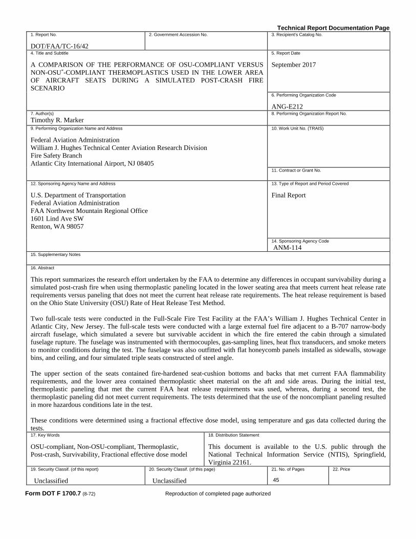
15. Supplementary Notes 16. Abstract This report summarizes the research effort undertaken by the FAA to determine any differences in occupant survivability during a simulated post-crash fire when using thermoplastic paneling located in the lower seating area that meets current heat release rate requirements versus paneling that does not meet the current heat release rate requirements. The heat release requirement is based on the Ohio State University (OSU) Rate of Heat Release Test Method. Two full-scale tests were conducted in the Full-Scale Fire Test Facility at the FAA’s William J. Hughes Technical Center in Atlantic City, New Jersey. The full-scale tests were conducted with a large external fuel fire adjacent to a B-707 narrow-body aircraft fuselage, which simulated a severe but survivable accident in which the fire entered the cabin through a simulated fuselage rupture. The fuselage was instrumented with thermocouples, gas-sampling lines, heat flux transducers, and smoke meters to monitor conditions during the test. The fuselage was also outfitted with flat honeycomb panels installed as sidewalls, stowage bins, and ceiling, and four simulated triple seats constructed of steel angle. The upper section of the seats contained fire-hardened seat-cushion bottoms and backs that met current FAA flammability requirements, and the lower area contained thermoplastic sheet material on the aft and side areas. During the initial test, thermoplastic paneling that met the current FAA heat release requirements was used, whereas, during a second test, the thermoplastic paneling did not meet current requirements. The tests determined that the use of the noncompliant paneling resulted in more hazardous conditions late in the test. These conditions were determined using a fractional effective dose model, using temperature and gas data collected during the tests. 17. Key Words OSU-compliant, Non-OSU-compliant, Thermoplastic, Post-crash, Survivability, Fractional effective dose model
18. Distribution Statement This document is available to the U.S. public through the National Technical Information Service (NTIS), Springfield, Virginia 22161.
19. Security Classif. (of this report) Unclassified
20. Security Classif. (of this page) Unclassified
21. No. of Pages 45
22. Price
Form DOT F 1700.7 (8-72) Reproduction of completed page authorized
iv
TABLE OF CONTENTS
Page
EXECUTIVE SUMMARY viii
1. INTRODUCTION 1
1.1 Purpose 1 1.2 Background 1
2. EXPERIMENTs 3
2.1 Laboratory Scale Tests 3 2.2 Full-Scale Tests 10 2.3 initial full-scale test using compliant materials 13 2.4 Follow-Up Test Using Non-Heat-Release-Compliant Materials 19 2.5 Comparison Of Heat-Release-Compliant Test to Non-Heat-Release-Compliant
2 OSU Test results for Boltaron thermoplastic material, trial 1 5
3 OSU Test results for Boltaron thermoplastic material, trial 2 6
4 OSU Test results for Boltaron thermoplastic material, trial 3 7
5 OSU Test results for nylon thermoplastic material, primary apparatus 8
6 OSU Test results for nylon thermoplastic material, secondary apparatus 9
7 Summary of OSU test results for thermoplastic materials 10
8 Schematic diagram of full-scale test fuselage 11
9 Schematic of test fuselage showing fire pan and seats 11
10 Mock-up triple seats used in full-scale tests 12
11 Mock-up seats with thermoplastic paneling mounted to sides and rear 13
12 Mock-up seats positioned inside full-scale test fuselage 14
13 Mock-up seats positioned inside full-scale test fuselage 14
14 External picture showing fully-developed fuel fire adjacent to test fuselage 15
15 Post test view of fuselage interior 16
16 Post test view of fuselage interior 17
17 Post test view of fuselage interior 18
18 Post test view of fuselage interior 18
19 Post test view of fuselage interior 19
20 Post test view of fuselage interior 20
21 Post test view of fuselage interior 21
22 Post test view of fuselage interior 21
23 Post test view of fuselage interior showing seat in fire opening 22
24 Post test view of fuselage interior showing forward seat 22
25 Post test view of fuselage interior showing damage to starboard-side seat 23
26 Post test view of fuselage interior showing damage to thermoplastic paneling 24
27 Post test view showing damage to thermoplastic paneling on seat positioned in fire opening 24
28 Post test view showing damage to thermoplastic paneling on starboard-side seat 25
29 Temperature comparison at the forward cabin area 26
vi
30 Temperature comparison at the mid cabin area 27
31 Temperature comparison at the mid cabin area 28
32 Heat flux comparison in test section 29
33 CO level comparison at forward cabin area 30
34 CO level comparison at mid cabin area 31
35 Oxygen level comparison at forward cabin area 32
36 Oxygen level comparison at mid cabin area 33
37 Survivability comparison for heat release compliant and non-compliant at the forward cabin area 34
38 Survivability comparison for heat release compliant and non-compliant tests at the mid cabin area 35
vii
LIST OF ACRONYMS ARAC Aviation Rulemaking Advisory Committee CO Carbon monoxide MFWG Materials Flammability Working Group
viii
EXECUTIVE SUMMARY
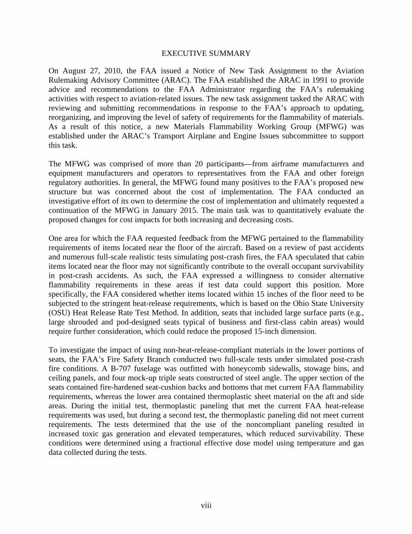
On August 27, 2010, the FAA issued a Notice of New Task Assignment to the Aviation Rulemaking Advisory Committee (ARAC). The FAA established the ARAC in 1991 to provide advice and recommendations to the FAA Administrator regarding the FAA’s rulemaking activities with respect to aviation-related issues. The new task assignment tasked the ARAC with reviewing and submitting recommendations in response to the FAA’s approach to updating, reorganizing, and improving the level of safety of requirements for the flammability of materials. As a result of this notice, a new Materials Flammability Working Group (MFWG) was established under the ARAC’s Transport Airplane and Engine Issues subcommittee to support this task. The MFWG was comprised of more than 20 participants—from airframe manufacturers and equipment manufacturers and operators to representatives from the FAA and other foreign regulatory authorities. In general, the MFWG found many positives to the FAA’s proposed new structure but was concerned about the cost of implementation. The FAA conducted an investigative effort of its own to determine the cost of implementation and ultimately requested a continuation of the MFWG in January 2015. The main task was to quantitatively evaluate the proposed changes for cost impacts for both increasing and decreasing costs. One area for which the FAA requested feedback from the MFWG pertained to the flammability requirements of items located near the floor of the aircraft. Based on a review of past accidents and numerous full-scale realistic tests simulating post-crash fires, the FAA speculated that cabin items located near the floor may not significantly contribute to the overall occupant survivability in post-crash accidents. As such, the FAA expressed a willingness to consider alternative flammability requirements in these areas if test data could support this position. More specifically, the FAA considered whether items located within 15 inches of the floor need to be subjected to the stringent heat-release requirements, which is based on the Ohio State University (OSU) Heat Release Rate Test Method. In addition, seats that included large surface parts (e.g., large shrouded and pod-designed seats typical of business and first-class cabin areas) would require further consideration, which could reduce the proposed 15-inch dimension. To investigate the impact of using non-heat-release-compliant materials in the lower portions of seats, the FAA’s Fire Safety Branch conducted two full-scale tests under simulated post-crash fire conditions. A B-707 fuselage was outfitted with honeycomb sidewalls, stowage bins, and ceiling panels, and four mock-up triple seats constructed of steel angle. The upper section of the seats contained fire-hardened seat-cushion backs and bottoms that met current FAA flammability requirements, whereas the lower area contained thermoplastic sheet material on the aft and side areas. During the initial test, thermoplastic paneling that met the current FAA heat-release requirements was used, but during a second test, the thermoplastic paneling did not meet current requirements. The tests determined that the use of the noncompliant paneling resulted in increased toxic gas generation and elevated temperatures, which reduced survivability. These conditions were determined using a fractional effective dose model using temperature and gas data collected during the tests.
1
1. INTRODUCTION
1.1 PURPOSE
This report describes the research undertaken by the FAA to determine the impact on occupant survivability when using non-heat-release-compliant materials in the lower portions of seats, as compared to the use of heat-release compliant materials. Two full-scale tests simulating a post-crash fire accident were conducted in a narrow-body B-707 fuselage to make this determination. 1.2 BACKGROUND
Research and full-scale testing were conducted at the FAA William J. Hughes Technical Center Full-Scale Fire Test Facility to determine the impact on survivability of thermoplastic paneling located in the lower portion of aircraft seats during a post-crash fire accident. This work was an outgrowth of an Aviation Rulemaking Advisory Committee (ARAC) task to determine the cost implications of upgrading, reorganizing, and improving the level of safety of requirements for the flammability of materials. The FAA established the ARAC in 1991 to provide advice and recommendations to the FAA Administrator regarding the FAA’s rulemaking activities with respect to aviation-related issues. As a result of this notice, a new Materials Flammability Working Group (MFWG) was established under the ARAC’s Transport Airplane and Engine Issues subcommittee to support this task. As discussed in the background section of the Notice issued by the FAA to task the ARAC in the August 27, 2010 Federal Register:
The flammability requirements for interior materials on transport category airplanes have evolved significantly over the years, and have become more threat-based. That is, a realistic test method based on the type of fire hazard most critical for the components in question. Historically, these requirements were based on a mix of threat, usage (e.g., sidewall), and material type (e.g., elastomeric materials). This has led to multiple requirements applying to the same component; conflicting requirements for the same component depending on what material it is made from; and ambiguous requirements for components not explicitly listed in §25.853 or Appendix F, part I. This last aspect results in the requirements of §25.853 or Appendix F, part I, being obsolete whenever materials change, or incomplete because components that have been developed since the regulation and Appendix F were issued are not specifically identified [1].
Prior to the Notice issued in the Federal Register, the FAA had fielded comments from industry on the difficulties with compliance to the existing Federal Aviation Regulations governing the flammability of interior cabin materials. Based on this, the FAA devised a simplified structure that would also increase the level of safety. As stated in the Federal Register Notice:
The FAA has drafted an approach that would simplify compliance demonstrations, and upgrade the level of safety for flammability throughout the airplane. The objective of the proposed approach is to completely revisit the flammability requirements and take advantage of the wealth of data available from FAA research and advances in material fire safety to provide a simpler regulation that provides a higher level of safety for transport category airplanes.
2
This initiative originated in response to a request by aviation industry organizations who participate in the International Aircraft Materials Fire Test Working Group. The working group is sponsored by the FAA’s William J. Hughes Technical Center and is not affiliated with the ARAC. The proposed approach would clearly delineate threat-based requirements, primarily based on a component’s function and location in the airplane. Appendix F to part 25 could be organized based on these threats, and the current part I, in particular, could be greatly simplified. In addition, this approach could include new requirements pertaining to inaccessible areas of the airplane, where in-flight fire is the greatest risk, by expanding the requirements to include air ducts and electrical wiring systems, as well as other high volume materials. This could include §25.855 for materials in cargo compartments. The approach would also generalize the requirements for heat release and smoke emissions to include all exposed large surface areas in the passenger cabin. This would eliminate the need for special conditions that are currently required for seats with nontraditional, large, non-metallic panels [1]
Because this task could result in a significant change to the Type Certification requirements, the FAA was very interested in obtaining international harmonization and specifically invited the participation of other regulatory authorities in developing the responses to the task. As such, the MFWG was comprised of more than 20 participants—from airframe manufacturers and equipment manufacturers and operators to representatives from the FAA and other foreign regulatory authorities. In general, the MFWG found many positives regarding the FAA’s proposed new structure, but it was concerned about the cost of implementation. The FAA conducted an investigative effort of its own to determine the cost of implementation and ultimately requested, in January 2015, a continuation of the MFWG. The main task was to quantitatively evaluate the proposed changes for cost impacts, for both increasing and decreasing costs. One area for which the FAA requested feedback from the MFWG pertained to the flammability requirements of items located near the floor of the aircraft. Based on a review of past accidents and numerous full-scale realistic tests simulating post-crash fires, the FAA speculated that cabin items located near the floor may not significantly contribute to the overall occupant survivability in post-crash accidents. As such, the FAA expressed a willingness to consider alternative flammability requirements in these areas if test data could support this position. More specifically, the FAA considered whether items located within 15 inches of the floor need to be subject to the stringent heat-release requirements or if a less stringent vertical Bunsen burner flammability test for these materials would suffice. In addition, seats that included large surface parts (e.g., large shrouded and pod-designed seats typical of business and first-class cabin areas) would require further consideration, which could reduce the proposed 15-inch dimension. To conduct this study, the FAA Fire Safety Branch identified two sets of thermoplastic sheet materials that could be used. The first material (Boltaron®) was a 0.125″ thick aircraft-grade PVC-acrylic material with low-heat release rate characteristics. A second nylon thermoplastic material of the same thickness was also selected, which met the vertical Bunsen burner requirement but not the more stringent heat-release requirement. Careful selection of materials
3
was critical to the study to ensure that an accurate assessment of the flammability requirements was made for materials located near the floor of the aircraft. 2. EXPERIMENTS
2.1 LABORATORY SCALE TESTS
Prior to conducting any full-scale realistic tests, the two sets of materials had to be laboratory tested to confirm they met the appropriate flammability criteria for the study. The first test was the 12-second vertical Bunsen burner test, which has been an FAA-required flammability test since 1967 [2]. The test subjects a 3″ x 12″ sample to a small, methane-fueled flame for a period of 12 seconds. There are essentially 3 measurements taken during the test [3]:
1. Flame time. Flame time is the time in seconds the specimen continues to flame after the
burner flame is removed from beneath the specimen. Surface burning that results in a glow but not in a flame is not included.
2. Drip flame time. Drip flame time is the time in seconds that any flaming material continues to flame after falling from the specimen to the floor of the chamber. If no material falls from the specimen, the drip flame time is reported to be 0 seconds and the notation “No Drip” is also reported. If there is more than one drip, the drip flame time reported is that of the longest flaming drip. If succeeding flaming drips reignite earlier drips that flamed, the drip flame time reported is the total of all flaming drips.
3. Burn length. Burn length is the distance from the original specimen edge to the farthest evidence of damage to the test specimen because of that area’s combustion, including areas of partial consumption, charring, or embrittlement but not including areas sooted, stained, warped, or discolored, or areas where material has shrunk or melted away from the heat.
Of these measurements, the requirements are as follows: 1. Flame time. The average flame time for all the specimens tested will not exceed
15 seconds for the 12-second vertical test. 2. Drip flame time. The average drip extinguishing time for all the specimens tested will not
exceed 5 seconds for the 12-second vertical test. 3. Burn length. The average burn length for all the specimens tested will not exceed
8″ (203 mm) for the 12-second vertical test. Figure 1 shows the vertical Bunsen burner test results for burn length of the two sets of materials. The results indicate that both sets of materials easily met the burn length requirement of 8-inch maximum.
A second battery of laboratory-scale tests was conducted using the OSU rate of heat-release apparatus. The current test apparatus is a modified version of the ASTM standard, ASTM E-906 [4]. This test standard became an FAA flammability requirement for large surface area cabin materials used in transport category aircraft. The new type certification standard was adopted in 1986, via amendment 25-61. Test samples measuring 6″x 6″, representing the completed interior component, are injected into an environmental chamber through which a constant flow of air passes. The sample is exposed to a radiant heat source adjusted to produce, on the sample, a total heat flux of 3.5 Watt/cm2. The sample is tested with the exposed surface oriented vertically, with combustion on the lower face area initiated by piloted ignition. The products of combustion leaving the chamber are monitored by an array of thermocouples to calculate the release rate of heat. During the 5-minute test, the peak heat-release rate is calculated in kW/m2 along with the total amount of heat released from the material during the first 2 minutes of exposure, expressed in kW-min/m2. These two parameters are referred to as the peak and total heat release rate, respectively. When the test standard became a requirement in 1988, the allowable peak heat- release rate was temporarily set at 100 kW/m2, and the 2-minute total was temporarily set at 100 kW-min/m2. These values were later reduced, in 1990, to 65 and 65 for the peak and total, respectively. These allowable heat release limits applied to all transport category airplanes with 20 seats or more.
5
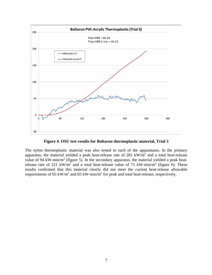
The FAA Fire Safety Branch had the benefit of operating two independent heat-release apparatuses at two of its facilities to offer more than a singular data point. Two test trials of the aircraft-grade thermoplastic were conducted in the primary apparatus, and a third test was conducted in a secondary apparatus for comparison. The test results yielded a peak heat-release rate of between 52 and 65 kW/m2 and total heat-release values between 44 and 58 kW-min/m2 (figures 2, 3, and 4). These results confirmed that this material met the current heat-release allowable requirements of 65 kW/m2 and 65 kW-min/m2 for peak and total heat-release, respectively.
Figure 2. OSU test results for Boltaron thermoplastic material, Trial 1
6
Figure 3. OSU test results for Boltaron thermoplastic material, Trial 2
7
Figure 4. OSU test results for Boltaron thermoplastic material, Trial 3
The nylon thermoplastic material was also tested in each of the apparatuses. In the primary apparatus, the material yielded a peak heat-release rate of 281 kW/m2 and a total heat-release value of 94 kW-min/m2 (figure 5). In the secondary apparatus, the material yielded a peak heat-release rate of 221 kW/m2 and a total heat-release value of 71 kW-min/m2 (figure 6). These results confirmed that this material clearly did not meet the current heat-release allowable requirements of 65 kW/m2 and 65 kW-min/m2 for peak and total heat-release, respectively.
8
Figure 5. OSU test results for nylon thermoplastic material, primary apparatus
9
Figure 6. OSU test results for nylon thermoplastic material, secondary apparatus
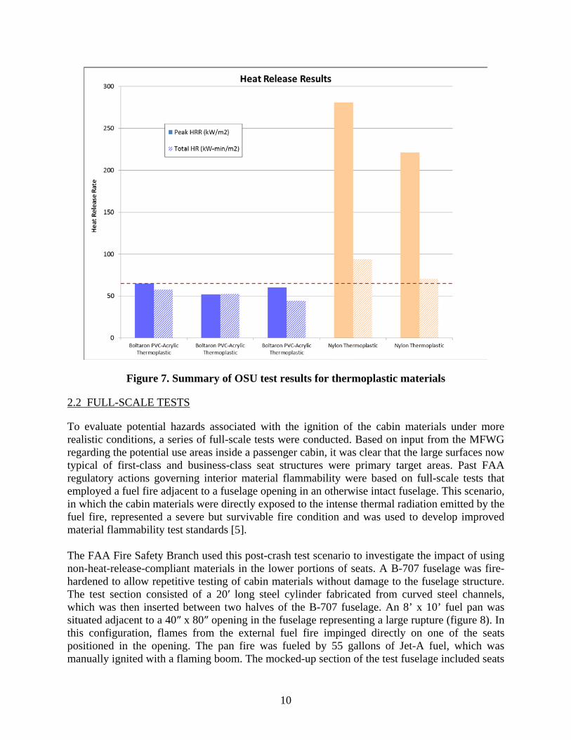
The heat-release results are summarized in figure 7. As shown, the aircraft-grade thermoplastic met the heat-release requirements, whereas the nylon thermoplastic did not. Because both materials met the 12-second vertical Bunsen burner requirements, the materials were suitable for a more realistic full-scale comparison.
10
Figure 7. Summary of OSU test results for thermoplastic materials
2.2 FULL-SCALE TESTS
To evaluate potential hazards associated with the ignition of the cabin materials under more realistic conditions, a series of full-scale tests were conducted. Based on input from the MFWG regarding the potential use areas inside a passenger cabin, it was clear that the large surfaces now typical of first-class and business-class seat structures were primary target areas. Past FAA regulatory actions governing interior material flammability were based on full-scale tests that employed a fuel fire adjacent to a fuselage opening in an otherwise intact fuselage. This scenario, in which the cabin materials were directly exposed to the intense thermal radiation emitted by the fuel fire, represented a severe but survivable fire condition and was used to develop improved material flammability test standards [5]. The FAA Fire Safety Branch used this post-crash test scenario to investigate the impact of using non-heat-release-compliant materials in the lower portions of seats. A B-707 fuselage was fire-hardened to allow repetitive testing of cabin materials without damage to the fuselage structure. The test section consisted of a 20′ long steel cylinder fabricated from curved steel channels, which was then inserted between two halves of the B-707 fuselage. An 8’ x 10’ fuel pan was situated adjacent to a 40″ x 80″ opening in the fuselage representing a large rupture (figure 8). In this configuration, flames from the external fuel fire impinged directly on one of the seats positioned in the opening. The pan fire was fueled by 55 gallons of Jet-A fuel, which was manually ignited with a flaming boom. The mocked-up section of the test fuselage included seats
11
and other cabin materials, such as sidewall, ceiling paneling, and carpet. The fuselage was also outfitted with thermocouple trees, gas sampling probes, smoke meters, and heat flux transducers to measure the conditions inside during the tests (figure 9). Video coverage of all tests was conducted with four interior cameras and two external cameras.
Figure 8. Full-scale test fuselage
Figure 9. Test fuselage showing fire pan and seats
The main objective of the full-scale tests was to determine whether an additional hazard was created during a cabin fire when non-heat-release-rate compliant materials were used in the
12
lower area of aircraft seats (i.e., 15″ or less above the cabin floor). To best accomplish the objective, a baseline hazard level had to be established during a test using materials that met the current heat-release requirements. The baseline test used mocked-up triple coach seats fabricated from steel angle. The mock-up design allowed not only the cushion material, but also the thermoplastic materials tested previously, to be mounted to the seat frames (figure 10).
Figure 10. Mock-up triple seats used in full-scale tests
As shown, the thermoplastic paneling was secured to the rear of the triple seat frame and to each side. The paneling was attached with screws and large-area washers to prevent the paneling from separating from the frame during the test. The thermoplastic paneling measured 15″ high x 20″ deep on each side and 15″ high by 56″ wide on the rear, for a total of 10 square feet of paneling per seat. The seat cushions were the standard size used in the FAA-required laboratory-scale flammability test. The seat cushions were fabricated from DAX® fire-hardened foam with a wool/nylon dress cover. Heat-release-compliant honeycomb paneling was also secured to the rear of all seat frames to simulate the large surface-area panels that are common on business and first-class seats (figure 11).
13
Figure 11. Mock-up seats with thermoplastic paneling mounted to sides and rear
Following the baseline test, a follow-on test was conducted in an identical manner, using thermoplastic lower seat materials that did not meet the current heat-release standards, but were compliant with the vertical Bunsen burner requirements. To maintain control, all other materials remained identical throughout the tests, therefore enabling an accurate assessment of only the non-heat-release compliant materials’ impact on the test outcome. 2.3 INITIAL FULL-SCALE TEST USING COMPLIANT MATERIALS
During the initial full-scale test, four of the mock-up triple seats were situated in the test fuselage to form a row of three seats on the rupture-side (port-side) of the fuselage, with one triple seat located across the aisle on the non-rupture starboard side (figures 12 and 13). Heat-release-compliant honeycomb core paneling was installed in the sidewall area of the rupture side and in the ceiling and stowage-bin areas to complete the test area. Aircraft-grade carpeting extended beyond the immediate test area by several feet; however, past testing had shown carpeting to contribute minimally during these types of experiments.
14
Figure 12. Mock-up seats positioned inside full-scale test fuselage
Figure 13. Alternate view of mock-up seats positioned inside full-scale test fuselage
15
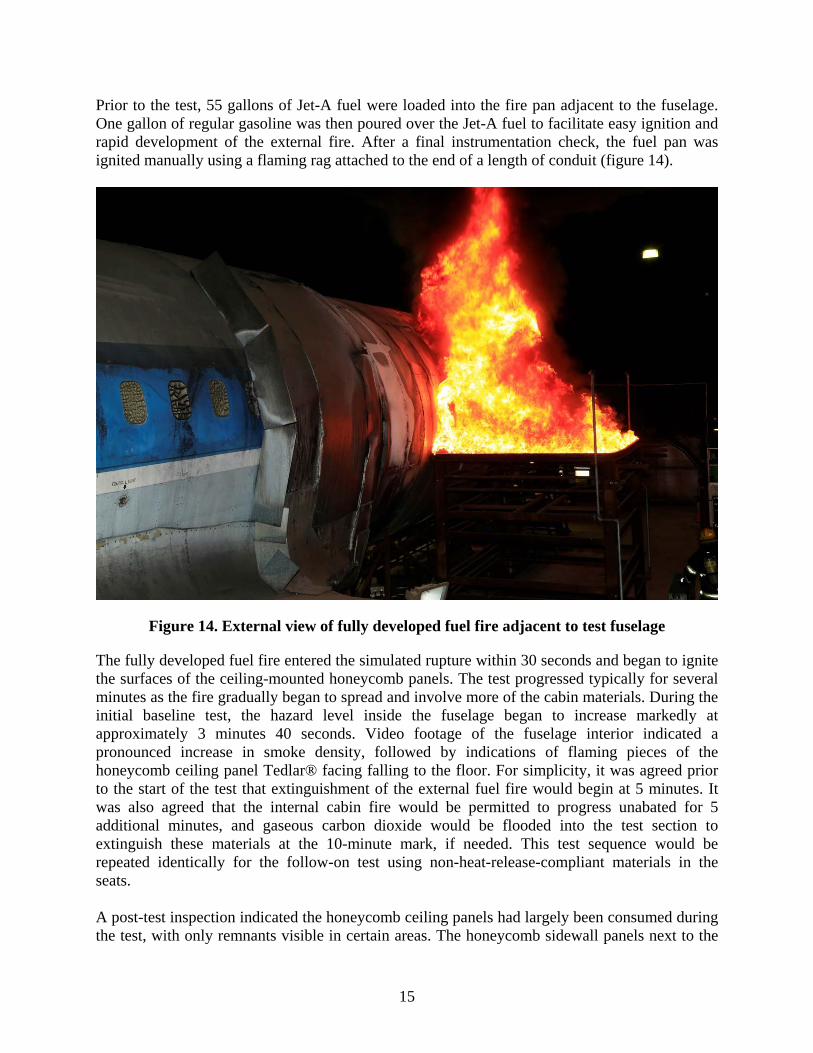
Prior to the test, 55 gallons of Jet-A fuel were loaded into the fire pan adjacent to the fuselage. One gallon of regular gasoline was then poured over the Jet-A fuel to facilitate easy ignition and rapid development of the external fire. After a final instrumentation check, the fuel pan was ignited manually using a flaming rag attached to the end of a length of conduit (figure 14).
Figure 14. External view of fully developed fuel fire adjacent to test fuselage
The fully developed fuel fire entered the simulated rupture within 30 seconds and began to ignite the surfaces of the ceiling-mounted honeycomb panels. The test progressed typically for several minutes as the fire gradually began to spread and involve more of the cabin materials. During the initial baseline test, the hazard level inside the fuselage began to increase markedly at approximately 3 minutes 40 seconds. Video footage of the fuselage interior indicated a pronounced increase in smoke density, followed by indications of flaming pieces of the honeycomb ceiling panel Tedlar® facing falling to the floor. For simplicity, it was agreed prior to the start of the test that extinguishment of the external fuel fire would begin at 5 minutes. It was also agreed that the internal cabin fire would be permitted to progress unabated for 5 additional minutes, and gaseous carbon dioxide would be flooded into the test section to extinguish these materials at the 10-minute mark, if needed. This test sequence would be repeated identically for the follow-on test using non-heat-release-compliant materials in the seats. A post-test inspection indicated the honeycomb ceiling panels had largely been consumed during the test, with only remnants visible in certain areas. The honeycomb sidewall panels next to the
16
fire opening were also heavily damaged, as were the mocked-up stowage bins (figure 15). The seat-cushion materials on the seat located directly in the fire opening were also mostly consumed, with only charred remnants remaining. The cushion material in the seats forward and aft of the seat in the fire opening was also heavily damaged by the interior fire. Although these seats on the port (fire opening) side of the fuselage were largely consumed, the fire did not fully cross over the aisle to the starboard side seat. Only a small percentage of the upper dress cover of the starboard seat sustained any fire damage, along with some charring of the exposed face of the bottom cushion (figure 16).
Figure 15. Post-test view of fuselage interior, facing aft
17
Figure 16. Post test view of fuselage interior, facing fire opening
As expected, the thermoplastic materials mounted on the seat positioned in the fire door had melted significantly. One concern prior to the test was that the thermoplastics would melt and fall completely to the floor and, therefore, not become a factor during the test. However, the post-test inspection revealed that the bolts and large-head washers were effective in keeping these materials secured in place (figure 17). Although the thermoplastic rear and side panels were almost completely consumed in the seat positioned in the fire opening, the thermoplastics located on seats forward and aft of this area were not nearly as consumed. The side panels of the forward seat were fairly intact, whereas the sides and rear panels in the aft seat showed some melting and charring, although they were still largely intact (figure 18). The thermoplastics mounted on the starboard-side seat were undamaged, except for some minor warping on the side facing the fire.
18
Figure 17. Post-test view of thermoplastic paneling on port-side seats
Figure 18. Post-test view of thermoplastic paneling on rear of port-side seat
19
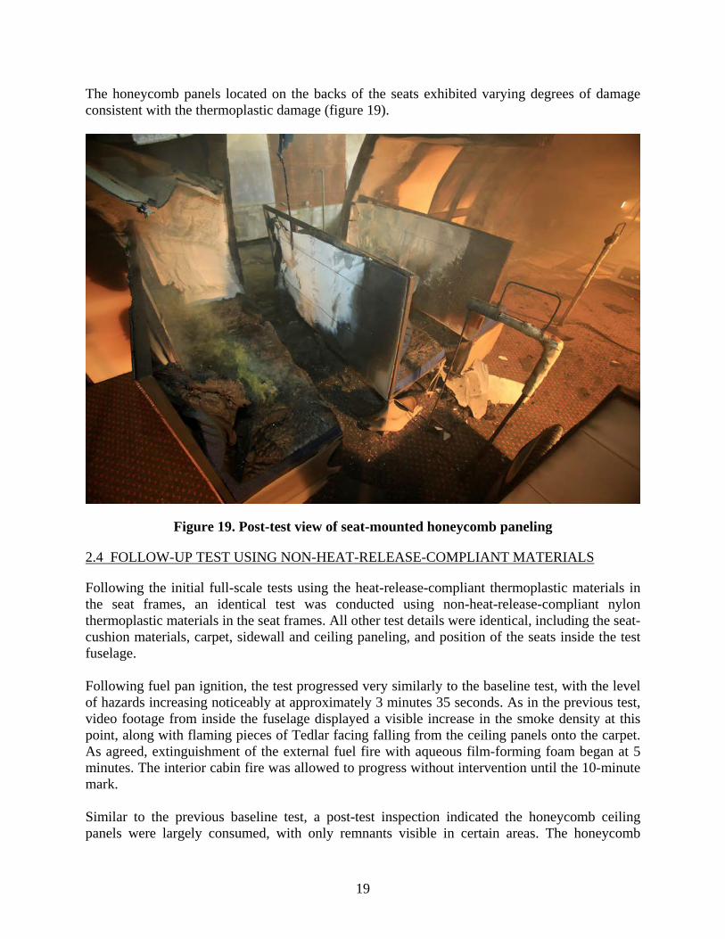
The honeycomb panels located on the backs of the seats exhibited varying degrees of damage consistent with the thermoplastic damage (figure 19).
Figure 19. Post-test view of seat-mounted honeycomb paneling
2.4 FOLLOW-UP TEST USING NON-HEAT-RELEASE-COMPLIANT MATERIALS
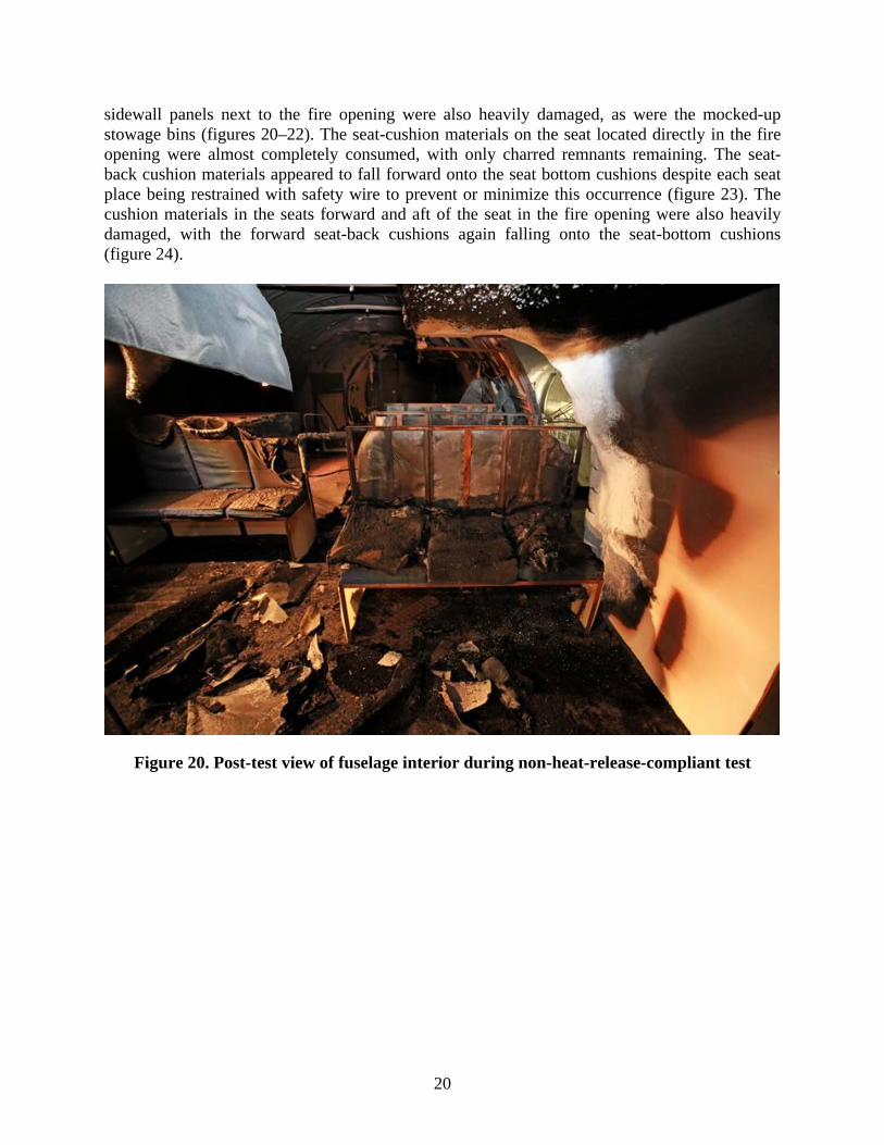
Following the initial full-scale tests using the heat-release-compliant thermoplastic materials in the seat frames, an identical test was conducted using non-heat-release-compliant nylon thermoplastic materials in the seat frames. All other test details were identical, including the seat-cushion materials, carpet, sidewall and ceiling paneling, and position of the seats inside the test fuselage. Following fuel pan ignition, the test progressed very similarly to the baseline test, with the level of hazards increasing noticeably at approximately 3 minutes 35 seconds. As in the previous test, video footage from inside the fuselage displayed a visible increase in the smoke density at this point, along with flaming pieces of Tedlar facing falling from the ceiling panels onto the carpet. As agreed, extinguishment of the external fuel fire with aqueous film-forming foam began at 5 minutes. The interior cabin fire was allowed to progress without intervention until the 10-minute mark. Similar to the previous baseline test, a post-test inspection indicated the honeycomb ceiling panels were largely consumed, with only remnants visible in certain areas. The honeycomb
20
sidewall panels next to the fire opening were also heavily damaged, as were the mocked-up stowage bins (figures 20–22). The seat-cushion materials on the seat located directly in the fire opening were almost completely consumed, with only charred remnants remaining. The seat-back cushion materials appeared to fall forward onto the seat bottom cushions despite each seat place being restrained with safety wire to prevent or minimize this occurrence (figure 23). The cushion materials in the seats forward and aft of the seat in the fire opening were also heavily damaged, with the forward seat-back cushions again falling onto the seat-bottom cushions (figure 24).
Figure 20. Post-test view of fuselage interior during non-heat-release-compliant test
21
Figure 21. Post-test view of seating materials during non-heat-release-compliant test
Figure 22. Post-test view of seating materials during non-heat-release-compliant test, view looking aft
22
Figure 23. Post-test view of fuselage interior showing seat in fire opening
Figure 24. Post-test view of fuselage interior showing forward port side seat
23
In addition to the port-side (fire opening) seats being largely consumed, there was also evidence the fire crossed over the aisle to the starboard side seat. The starboard side seat was significantly fire damagedmoderately , with the seat back closest to the fire door nearly consumed (figure 25). This was a noticeable difference from the previous test, in which the fire caused only minor charring of the starboard seat.
Figure 25. Post-test view of fuselage interior showing damage to starboard-side seat
As anticipated, the thermoplastic materials mounted on the seat positioned in the fire door had melted significantly. Although the rear and side panels were completely consumed in this seat, the thermoplastics located on the sides of the seat forward of this were not nearly as consumed. The fastening method employing the bolts and large-head washers was again effective in preventing the thermoplastic materials from falling to the floor (figure 26). However, the side and rear panels of the aft seat were also completely consumed (figure 27). This represented a noticeable difference from the previous test, in which the thermoplastics located in these areas were still somewhat intact. The thermoplastics mounted on the starboard-side seat were undamaged, except for some minor warping on the side facing the fire (figure 28).
24
Figure 26. Post-test view of fuselage interior showing damage to thermoplastic paneling
Figure 27. Post-test view showing damage to thermoplastic paneling on seat positioned in fire opening
25
Figure 28. Post-test view showing damage to thermoplastic paneling on starboard-side seat
2.5 COMPARISON OF HEAT-RELEASE-COMPLIANT TEST TO NON-HEAT-RELEASE-COMPLIANT TEST
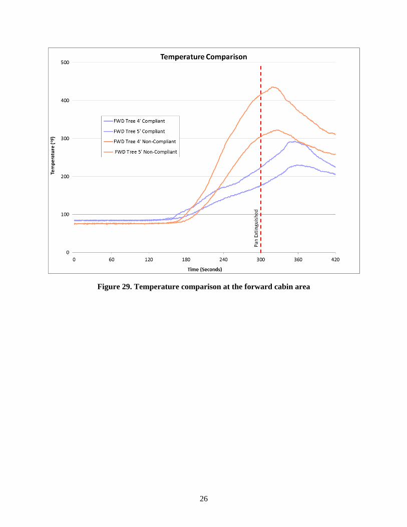
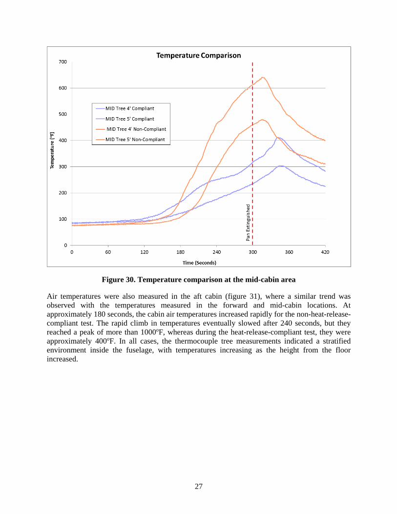
To effectively evaluate the performance of the two materials, several comparative charts are presented. These charts compare the fuselage interior conditions for the baseline heat-release-compliant thermoplastic materials to the non-heat-release-compliant thermoplastic materials. The forward cabin temperatures, measured at heights between 4′ and 5′ above the floor, indicated similar temperatures up until approximately 180 seconds into the test. Shortly after this point, the temperatures at this location increased markedly during the test using the non-heat-release-compliant materials (figure 29). At the 5′ elevation, the temperatures exceeded 400oF at the point of pan fire extinguishment, whereas the compliant material test reached only 220oF. A similar trend was observed at the mid-cabin temperature tree, which was located closer to the burning materials (figure 30). The temperature separation between the two tests was even more pronounced, with the noncompliant material test reaching more than 600oF and the compliant material test only slightly exceeding 300oF.
26
Figure 29. Temperature comparison at the forward cabin area
27
Figure 30. Temperature comparison at the mid-cabin area
Air temperatures were also measured in the aft cabin (figure 31), where a similar trend was observed with the temperatures measured in the forward and mid-cabin locations. At approximately 180 seconds, the cabin air temperatures increased rapidly for the non-heat-release-compliant test. The rapid climb in temperatures eventually slowed after 240 seconds, but they reached a peak of more than 1000oF, whereas during the heat-release-compliant test, they were approximately 400oF. In all cases, the thermocouple tree measurements indicated a stratified environment inside the fuselage, with temperatures increasing as the height from the floor increased.
28
Figure 31. Second temperature comparison at the mid-cabin area
Heat flux measurements were taken in the immediate area of the seats and paneling via three water-cooled heat flux transducers. The transducers were positioned horizontally at a height of 42″ above the floor. This provided a good comparative measurement of the conditions in the test section. One transducer was in front of the seats, facing aft, and another was aft of the seats, facing forward. A third instrument faced directly out toward the fire entry opening. Similar to the temperature profiles measured from the thermocouple trees, the heat flux measurements were nearly identical for the first 180 seconds of the test. At the 180-second point, the heat flux shows a marked rise during the test of the non-heat-release-compliant material, as measured by the mid-calorimeter facing the fire (figure 32). The heat flux at this location reached a maximum of approximately 6 Btu/ft2 sec, whereas it reached only 3 Btu/ft2 sec during the heat-release-compliant test.
29
Figure 32. Heat flux comparison in test section
The data obtained for the carbon monoxide (CO) levels followed the same trend as the temperature and heat flux data. The forward cabin area CO levels (measured at 3′6″ and 5′6″) began to increase above trace levels between 140 and 200 seconds into the test, with the 5′6″ level rising before the 3′6″ level in both tests (figure 33). This was expected because the stratified layer of gases filled the upper section of the fuselage and then progressed downward. At the 5′6″ level, the gas measurements were nearly identical for both tests until the 180-second point. After this, the CO level increased rapidly for the non-heat-release-compliant material, reaching a level of approximately 0.9% at the 5-minute mark. During the test using heat-release-compliant materials, the level reached only 0.3% at the 5-minute mark. Similar results were also obtained at the 3′6″ level.
30
Figure 33. CO level comparison at forward cabin area
The mid-cabin area CO levels (measured at 3′6″ to 5′6″) showed a much more erratic behavior, indicating greater turbulence in the cabin air at this location (figure 34). This was anticipated because there is typically more air movement closer to the fire. Although less clear than the forward cabin station, the CO levels began to increase above trace levels between 130 and 180 seconds into the test, with the 5′6″ level again rising before the 3′6″ level in both tests because of stratification. At the 5′6″ level, the gas measurements were nearly identical for both tests until the 150-second point. After this, the CO level increased and decreased rapidly for several iterations for the non-heat-release-compliant material, reaching a level of approximately 1.5% at the 5-minute mark. During the test using heat-release-compliant materials, the level reached only 0.3% at the 5-minute mark. At a height of 3′6″ above floor, the non-heat-release-compliant materials reached a maximum of 0.7%, whereas the heat-release-compliant material reached a maximum of approximately 0.3%.
31
Figure 34. CO level comparison at mid-cabin area
Oxygen depletion was also recorded and showed much the same delay and trending between the two tests compared (figures 35 and 36). At the forward cabin area, the oxygen levels dropped to between 12% and 18% at the point where the external fuel fire was being extinguished (figure 35). As with the CO measurements, the oxygen depletion was recorded at the 5′6″ height before occurring at the 3′6″ height. The oxygen depletion began at approximately 160 seconds at the upper measuring level, and 200 seconds at the lower level.
32
Figure 35. Oxygen level comparison at forward cabin area
33
Figure 36. Oxygen level comparison at mid-cabin area
At the mid-cabin location, closer to the fire, the oxygen depletion began to occur at 150 seconds at the 5′6″ level and 190 seconds at the 3′6″ level. At the point of extinguishment of the external fuel fire, the oxygen levels had dropped to between 13% and 15% for the non-heat-release-compliant materials and approximately 18%–19% for the heat-release-compliant materials. As expected, the mid-cabin oxygen levels were not as uniform (figure 36), indicating less stratification and more mixing because of this area’s closer proximity to the burning materials. Flashover is a condition in which the combustion gases generated from the burning materials suddenly ignite, producing extreme temperatures and simultaneously consuming a large quantity of the available oxygen in the cabin space. During flashover, the oxygen level typically drops to between 12% and 13%. Based on the data obtained during both tests, it is apparent that a flashover condition occurred during the test using the non-heat-release-compliant materials. The flashover condition during this test is supported not only by the oxygen depletion (12% to 13%), but also the corresponding rapid temperature, heat flux, and CO rise shown in the preceding plots. A survivability model was used to predict the theoretical time at which a person would become incapacitated based on the levels of temperature and gases measured during the test. After inputting all the temperature and gas measurement data from the tests, the model generated
34
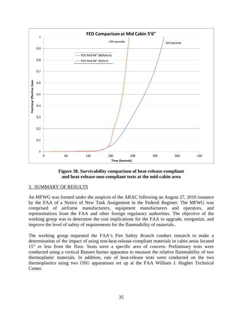
fractional effective dose (FED) survivability curves [6]. The survival time corresponds to FED=1.0. The results from this two-test comparison showed a marked decrease in survivability when the non-compliant thermoplastic materials were used. At the forward cabin area, theoretical incapacitation was reached in 402 seconds for the heat-release-compliant material test, but only 280 seconds for the non-heat-release-compliant materials (figure 37). Although the initial increase in hazard level within the fuselage was nearly identical for the two tests (3 minutes 40 seconds for the compliant materials, and 3 minutes 35 seconds for the non-compliant materials) this was a significant (122-second) difference between the two tests. This indicates the non-heat-release-compliant materials produced more substantial fire growth, resulting in reduced time until incapacitation. Likewise, at the mid-cabin location, the non-heat-release-compliant materials resulted in incapacitation 94 seconds earlier than when using heat-release-compliant materials (figure 38). These results were a clear indication that despite nearly identical initial test sequences (up to approximately 180 seconds) the non-compliant materials allowed greater fire growth and increased levels of hazard to occur.
Figure 37. Survivability comparison of heat-release-compliant and heat-release-non-compliant tests at the forward cabin area
35
Figure 38. Survivability comparison of heat-release-compliant and heat-release-non-compliant tests at the mid-cabin area
3. SUMMARY OF RESULTS
An MFWG was formed under the auspices of the ARAC following an August 27, 2010 issuance by the FAA of a Notice of New Task Assignment in the Federal Register. The MFWG was comprised of airframe manufacturers, equipment manufacturers and operators, and representatives from the FAA and other foreign regulatory authorities. The objective of the working group was to determine the cost implications for the FAA to upgrade, reorganize, and improve the level of safety of requirements for the flammability of materials.. The working group requested the FAA’s Fire Safety Branch conduct research to make a determination of the impact of using non-heat-release-compliant materials in cabin areas located 15″ or less from the floor. Seats were a specific area of concern. Preliminary tests were conducted using a vertical Bunsen burner apparatus to measure the relative flammability of two thermoplastic materials. In addition, rate of heat-release tests were conducted on the two thermoplastics using two OSU apparatuses set up at the FAA William J. Hughes Technical Center.
36
Preliminary tests determined the burn length of two different types of thermoplastic to be relatively low as measured using the Bunsen burner apparatus. Subsequent heat-release tests of the materials found vast differences, with one material passing the current 65/65 requirement, but the other material convincingly failing the requirement. The preliminary tests formed the basis for realistic full-scale tests conducted inside a mocked-up B-707 aircraft fuselage with a large jet fuel fire entering the fuselage through an opening. A test was initially conducted using heat-release-compliant thermoplastic materials located in the lower area of mocked-up seats to establish a baseline hazard level inside the fuselage. In a subsequent test, thermoplastic materials were used that were not compliant with the FAA’s stringent heat-release rate requirement for comparison. Although the tests progressed similarly for the initial 180 seconds, they confirmed that a significant change to survivability (based on a survivability model) resulted when using non-heat-release-compliant thermoplastics in the lower portion of the mocked-up seats. 4. CONCLUSIONS
Aviation industry representatives requested that the FAA conduct research to investigate the feasibility of allowing non-heat-release-compliant materials to be used in the lower areas of the cabin as a cost-savings measure. Specifically, the industry inquired into the use of non-heat-release-compliant panels to be used in areas 15″ (or less) from the floor, and in particular those on seats. The industry’s expectation was that materials located in these lower areas would not significantly contribute to the increase in hazard-level during a post-crash fire accident. The opportunity for cost savings was certain if testing could show that non-heat-release-compliant materials did not increase the level of hazard. A formal research project was initiated to secure the appropriate materials for initial laboratory-scale flammability and heat-release testing. The initial testing led to the selection of two thermoplastic materials for use in a realistic, full-scale demonstration simulating a post-crash fire accident. These realistic tests confirmed that an additional hazard was, in fact, created inside the cabin when using aircraft seats employing non-heat-release-rate-compliant thermoplastics—when compared to a test using heat-release-compliant materials.
37
5. REFERENCES
1. FAA Federal Register. (2010). Aviation Rulemaking Advisory Committee; Transport Airplane and Engine Issues-New Task, Document 2010-21333.
2. Compartment Interiors. 14 CFR §25.853 (1995).
3. FAA. (2000). Aircraft Materials Fire Test Handbook, Chapter 1, (DOT/FAA/AR-00/12).
4. FAA. (2000). Aircraft Materials Fire Test Handbook, Chapter 5, (DOT/FAA/AR-00/12).
5. FAA. (1988) Development of improved fire safety standards adopted by the Federal Aviation Administration. Proceedings from Propulsion and Energetics Panel 73rd Symposium on Aircraft Fire Safety/Sintra, Portugal: Sarkos.
6. FAA Report. (1995). Toxicity Assessment of Combustion Gases and Development of a Survival Model (DOT/FAA/AR-95/5).