Page 1
7/30/2019 A Computational Study on the Flow Characteristics of a Self-compensating Liquid Balancer
http://slidepdf.com/reader/full/a-computational-study-on-the-flow-characteristics-of-a-self-compensating-liquid 1/10
Journal of Mechanical Science and Technology 25 (6) (2011) 1465~1474
www.springerlink.com/content/1738-494xDOI 10.1007/s12206-011-0407-y
A computational study on the flow characteristics of a self-compensatingliquid balancer †
Chung-Hyo Jung1, Jin-Tak Kim2 and Yun-Ho Choi2,* 1Samsung Electronics CO., LTD., 416, Maetan-3Dong, Yeongtong-Gu, Suwon-City, Korea
2 Department of Mechanical Engineering, Ajou University, Suwon, Korea
(Manuscript Received July 2, 2010; Revised February 21, 2011; Accepted April 4, 2011)
----------------------------------------------------------------------------------------------------------------------------------------------------------------------------------------------------------------------------------------------------------------------------------------------
Abstract
An automatic washing machine undergoes rotational unbalance due to unbalanced mass during the spinning process. A liquid balancer
is an assembly that plays a role in controlling this unbalance. In recent years, washing machines (drum and automatic types) are becom-ing larger to handle large laundry items such as comforters. A large-sized washing machine generates a huge centrifugal force in its high
speed rotating drum. Thus, a specific vibration reduction technique is required. The design of a liquid balancer has, to date, depended on
conventional methods such as experiments and dynamic models. A dynamic model classifies the behavior of liquid inside the balancer
into three different patterns, and solutions can be obtained by approximating these patterns as rigid bodies. This method, however, is
limited to two-dimensional (2-D) analysis for simple geometry. In the present study, a three dimensional (3-D) computational fluid dy-
namics (CFD) method is used to analyze flow characteristics inside the liquid balancer for various design parameters. The main parame-
ters include rotational speed, eccentricities of the center of rotation, viscosity of the liquid, gravity orientation, surface tension, and the
number of baffles. In particular, the effects of these parameters on the hydraulic force (restoration force) of the liquid balancer are studied.
Keywords: Automatic washing machine; Liquid balancer; CFD; Dynamic model; Free surface; VOF; Centrifugal force; Baffle; Restoration force; Eccen-tricity
----------------------------------------------------------------------------------------------------------------------------------------------------------------------------------------------------------------------------------------------------------------------------------------------
1. Introduction
A liquid balancer is a device or part that controls vibration
caused by unbalanced mass during the spinning process. Two
types of problems are caused by such vibration: 1) the colli-
sion between the tub and the frame of a washing machine in
the early spinning process, and 2) whirling vibration occurring
in the steady state. The performance of a liquid balancer can
be improved by solving these problems.
In the previous study [1], we reviewed the structure of an
automatic washing machine and the role of the balance control
system, and proposed an alternative method that improves the
performance of such a balancer by establishing a dynamicmodel. Also, we investigated a method that prevents liquid
deflection from occurring at the early transient state using
CFD calculations. Some of our results were applied to actual
products, and improvements were made to enhance product
quality. Our company’s washing machines with capacities of
6 kg, 7 kg, and 8 kg employ a two-race balancer, and it was
found that whirling vibration could be suppressed more easilyat normal rotational speed by a two-race balancer than by a
one-race balancer.
The recent trend in the development of automatic washing
machines is to make large products due to the demands of
customers who have large laundry items such as comforters.
One of the key technologies required in the design of large-
scale washing machines is a vibration reduction. As previ-
ously mentioned, it is necessary to introduce a two-race balan-
cer in large-scale washing machines to reduce the rotational
vibration of the basket. Before dynamic modeling and the
computational fluid dynamics (CFD) method were established,
designers used the trial and error method by building testmock-ups. Dynamic modeling and the CFD method are being
used to develop a large-scale washing machine and to help
improve the performance of existing machines. In the present
study, we introduced the CFD method to deduce design pa-
rameters such as the shape and number of baffles, and to un-
derstand the self-excited oscillation [2] that cannot be ana-
lyzed using a dynamic model.
No studies have been reported on the shape and number of
baffles required to prevent the self-excited oscillation of liquid.
Saito et al. [3] investigated self-excited oscillation occurring
during the rotation of a dual concentric cylinder using a finite
† This paper was recommended for publication in revised form by Associate Editor
Gihun Son*Corresponding author. Tel.: +82 31 219 2346, Fax.: +82 31 219 1611
E-mail address: [email protected]
© KSME & Springer 2011
Page 2
7/30/2019 A Computational Study on the Flow Characteristics of a Self-compensating Liquid Balancer
http://slidepdf.com/reader/full/a-computational-study-on-the-flow-characteristics-of-a-self-compensating-liquid 2/10
1466 C.-H. Jung et al. / Journal of Mechanical Science and Technology 25 (6) (2011) 1465~1474
difference method. Also, they presented a relationship be-
tween external damping and the self-excited oscillation, and
obtained a numerical solution for fluid force [4]. In addition,
the stability threshold at low and high speed regimes obtained
from their experiments was nearly identical to numerical re-
sults. Kaneko et al. [5] investigated the periodic characteristics
of centrifugal force waves in a free surface, and established a
boundary layer theory. Although there are many studies using
such dynamic models, no studies are available which directly
use numerical simulation to investigate fluid force and freesurface.
The purpose of the present study is to investigate flow char-
acteristics and to understand flow physics inside the liquid
balancer to help make a better design of liquid balancer. For
this, we used both an analytical method and a CFD method.
For analytical method, two dynamic models are constructed,
one of which is to compute the heights of liquid columns and
the other is to compute the fluid forces. For CFD method, we
made two and three dimensional CFD computations to study
various design parameters. These parameters include eccen-
tricities of the center of rotation, rotational speeds, gravity
orientation, number of baffles and their shape, and number of races. In particular, the effects of these parameters on the hy-
draulic forces of the liquid balancer have been studied.
2. Calculation of the height of a liquid column
2.1 Dynamic model
The liquid inside the balancer rotates on its axis with angu-
lar velocity ω, and behaves as a rigid body after an early tran-
sition process. In Ref. [1], we classified the rigid body rotation
into three types. One type is a linear model, as shown in Fig. 1.
Within the linear range, the inner height hinner and outer height
houter of the liquid columns [6, 7] can be obtained using Eq. (3).
Here, Eq. (3) can be obtained by combining Eqs. (1) and (2)representing an isobaric surface of liquid and the total liquid
volume, respectively.
2 2
02
i Rh constant
g
ω − = (1)
2o
i
R
RV rhdr π = ∫ (2)
( )2
2 2 224
i oh r R R H g
ω = − − + (3)
Also, liquid in the linear range passes through the liquid
contact state and reaches the liquid break state due to an in-
crease in rotational speed as shown in Fig. 2. The isobaric
surface at the liquid break state cannot be computed using Eq.
(3) for the inner/outer heights, as is done in the linear range.
However, the isobaric surface can be obtained using the fol-
lowing equation assuming there exists some water on the bot-
tom and the top surfaces of the balancer:
2 2
1 .2
o Rh constant
g
ω + = (4)
The total liquid volume at the liquid break state can be ob-
tained using
( )2 22upper
lower
R
o upper t R
V rhdr R R H π π = + −∫ . (5)
The height of liquid columns can be calculated using Eqs.
(4) and (5) as follows:
2 22
2
2 22
2
2
.2
t i oupper
t i olower
gH R R R
gH R R R
ω
ω
+= +
+= − +
(6)
2.2 Calculation of the free surface
In order to calculate the free surface of a liquid balancer that
does not have an eccentricity, we considered a two-
dimensional (2-D) computational model as illustrated in Fig. 3.
This is because the flow inside the balancer is axisymmetric
when the eccentricity is not present. The width and height of
the balancer is 1.02 cm and 6.95 cm, respectively, and the
radius from the center of rotation to the outer wall is 20.98 cm.
Also, for our calculations, the Fluent v6.3 code was used, with
the steady/unsteady turbulent Navier-Stokes equations. The
computational domain was divided into lower and upper re-
gions which were filled with water and air, respectively. A
volume of fluid (VOF) model [8] was used to simulate the
mixture fluid phase, and a standard k-ε model was used for the
turbulence calculations. The calculation was performed for six
H2H=Htotal
hinner
Rinner
Router
H2H=Htotal
hinner
Rinner
Router
Fig. 1. Linear model of the fluid in a liquid balancer.
Rinner
Rlower
Rupper
Router
Rinner
Rlower
Rupper
Router
Fig. 2. Liquid-break model of the fluid in a liquid balancer.
Page 3
7/30/2019 A Computational Study on the Flow Characteristics of a Self-compensating Liquid Balancer
http://slidepdf.com/reader/full/a-computational-study-on-the-flow-characteristics-of-a-self-compensating-liquid 3/10
C.-H. Jung et al. / Journal of Mechanical Science and Technology 25 (6) (2011) 1465~1474 1467
different rotational speeds ranged from 50 r/min to 700 r/min
(refer to Fig. 4). In addition, this calculation was made onlyfor the steady state by simplifying nonlinear phenomena into
linear phenomena. Table 1 shows the properties of the fluid
used in the calculation. The number of grids used in the calcu-
lation was 27,380.
Fig. 4 illustrates the shape of the free surface [9] obtained
for various rotational speeds. If water moves in a closed space
due to a rotational force, water gradually climbs upward along
the outer wall in the early stage of the rotation. Then, water
reaches the top surface at speeds higher than 200 r/min. As
rotational speed increases, the water stands up as a liquid col-
umn because the centrifugal force is significantly larger than
the gravity due to the weight of water. Although the free sur-
face varies linearly as rotational speed increases, the actual
shape may show fluctuations at low speeds. This is due to the
fact that the rotation is unstable at such low speeds because the
natural frequency of a suspension system exists at 60~80
r/min [10]; furthermore, uneven distribution of laundries in-
side the basket generates an unbalanced force. In addition, as
the rotation approaches steady state, a whirling vibration that
represents nonlinearity appears. This whirling vibration will
generate fluctuations on the free surface in the rotational direc-tion instead of keeping a constant shape on the free surface.
Fig. 5 shows a comparison of the heights of liquid columns
obtained by the dynamic model (Eqs. (3) and (6)) and CFD
calculations. Although surface tension cannot be considered in
the dynamic model, the heights of the liquid columns were
compared according to the existence of surface tension (the
CFD calculations can consider the surface tension). For calcu-
lations that do not consider surface tension, the heights of
liquid columns obtained by these two methods agree with
each other. As shown in Fig. 5, surface tension has an effect
on the free surface below 200 r/min. However, when the bal-
ancer rotates at higher than 200 r/min, there are no changes in
the free surface regardless of the existence of surface tension
[11]. The fluctuations occurring on the free surface in actual
phenomena are due to the unbalanced force of a rotating body.
In addition, the free surface will also be deformed [12-14],
even with a very small force (or factor), when the balancer
rotates with an unstable center of rotation.
Kaneko et al. [4] suggested that flow velocities of liquid in-
side the rotating cylinder depend on kinematic viscosities of
the liquid. Although the radial velocity was not influenced by
the variation of kinematic viscosities, the tangential velocity
exhibited a sudden change near the outer wall due to the varia-
Table 1. Fluid properties at 298.15 K.
Properties Air Water Oil(SAE30)
Density (kg/m3) 1.225 998.2 600
Dynamic viscosity
(kg/m·s)1.7894e-5 1.003e-3 3.8e-1
Fig. 3. Two-dimensional computational model.
Fig. 4. Shapes of the free surface for various values in ω (2-D calcula-
tion).
Fig. 5. Comparison of CFD and dynamic model solutions for water
levels.
Page 4
7/30/2019 A Computational Study on the Flow Characteristics of a Self-compensating Liquid Balancer
http://slidepdf.com/reader/full/a-computational-study-on-the-flow-characteristics-of-a-self-compensating-liquid 4/10
1468 C.-H. Jung et al. / Journal of Mechanical Science and Technology 25 (6) (2011) 1465~1474
tion of kinematic viscosities.
It has been reported that boundary layers are not formed. In
order to study this behavior, CFD calculations were made for
a one-race model with the conditions of no eccentricity e and
no baffles at 700 r/min.
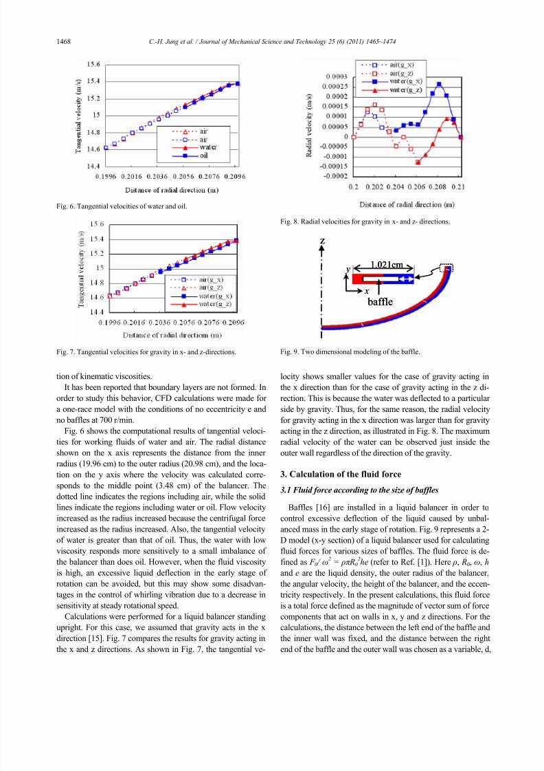
Fig. 6 shows the computational results of tangential veloci-
ties for working fluids of water and air. The radial distance
shown on the x axis represents the distance from the inner
radius (19.96 cm) to the outer radius (20.98 cm), and the loca-
tion on the y axis where the velocity was calculated corre-
sponds to the middle point (3.48 cm) of the balancer. The
dotted line indicates the regions including air, while the solid
lines indicate the regions including water or oil. Flow velocity
increased as the radius increased because the centrifugal force
increased as the radius increased. Also, the tangential velocity
of water is greater than that of oil. Thus, the water with lowviscosity responds more sensitively to a small imbalance of
the balancer than does oil. However, when the fluid viscosity
is high, an excessive liquid deflection in the early stage of
rotation can be avoided, but this may show some disadvan-
tages in the control of whirling vibration due to a decrease in
sensitivity at steady rotational speed.
Calculations were performed for a liquid balancer standing
upright. For this case, we assumed that gravity acts in the x
direction [15]. Fig. 7 compares the results for gravity acting in
the x and z directions. As shown in Fig. 7, the tangential ve-
locity shows smaller values for the case of gravity acting in
the x direction than for the case of gravity acting in the z di-
rection. This is because the water was deflected to a particular
side by gravity. Thus, for the same reason, the radial velocity
for gravity acting in the x direction was larger than for gravity
acting in the z direction, as illustrated in Fig. 8. The maximum
radial velocity of the water can be observed just inside the
outer wall regardless of the direction of the gravity.
3. Calculation of the fluid force
3.1 Fluid force according to the size of baffles
Baffles [16] are installed in a liquid balancer in order to
control excessive deflection of the liquid caused by unbal-
anced mass in the early stage of rotation. Fig. 9 represents a 2-
D model (x-y section) of a liquid balancer used for calculatingfluid forces for various sizes of baffles. The fluid force is de-
fined as F 0 / ω2
= ρπ R02he (refer to Ref. [1]). Here ρ, R0, ω, h
and e are the liquid density, the outer radius of the balancer,
the angular velocity, the height of the balancer, and the eccen-
tricity respectively. In the present calculations, this fluid force
is a total force defined as the magnitude of vector sum of force
components that act on walls in x, y and z directions. For the
calculations, the distance between the left end of the baffle and
the inner wall was fixed, and the distance between the right
end of the baffle and the outer wall was chosen as a variable, d,
Fig. 6. Tangential velocities of water and oil.
Fig. 7. Tangential velocities for gravity in x- and z-directions.
Fig. 8. Radial velocities for gravity in x- and z- directions.
z
x
y1.021cm
baffle
z
x
y
x
y1.021cm
baffle
1.021cm
baffle
Fig. 9. Two dimensional modeling of the baffle.
Page 5
7/30/2019 A Computational Study on the Flow Characteristics of a Self-compensating Liquid Balancer
http://slidepdf.com/reader/full/a-computational-study-on-the-flow-characteristics-of-a-self-compensating-liquid 5/10
C.-H. Jung et al. / Journal of Mechanical Science and Technology 25 (6) (2011) 1465~1474 1469
as shown in the figure (the enlarged section marked by a dot-
ted line). For d, 0%, 5%, and 15% of the width of the balancer
(1.021 cm) were used. Twelve baffles were used and they are
installed with equal spacing. The rotational speed of the bal-ancer and the eccentricity is 1000 r/min and 5 mm, respec-
tively. The transient analysis was performed for up to 11 s.
Fig. 10 shows the computational results using a dynamic
model and the CFD method. It can be seen that the fluid force
increased rapidly as the gap between the baffles and the outer
wall increased. The reason might be because water can re-
spond sensitively to an unbalanced rotating body due to the
increase in mobility of the water. However, the liquid can be
excessively deflected for a large gap in the early transient state,
and this might lead to an increase in the number of collisions
between the basket and the tub. Considering this, we note that
the desirable gap size (d) is about 5% of the width of the baffle.
For this case, as shown in Fig. 10, the fluid force approaches
its analytical value in 11 s after starting to rotate.
3.2 Fluid force according to eccentricity
In this section, the previous 2-D calculation is extended to
three dimensions, and a parametric study for various eccen-
tricities is described. Fig. 11 shows the shape of the baffles
installed on the outer wall of an actual product. First, the com-
putations were made without considering baffles. The rotating
speed and eccentricity used for this calculation are in the range
of 0~1000 r/min and 0~15 mm, respectively. The working
fluids are water and air, and the water volume fraction is set to0.5. The fluid force was obtained from the dynamic model as
follows:
( ) ( )( ){( ) ( )( ) }
2 2 2
2
/ sin cos
-sin cos .
o o o
i
F he R R
R
ω ρ π β β β
δ δ δ
= − −
−
(7)
This equation is a generalized form of the equation for the
fluid force (restoration force) derived in our previous study [1].
The constants β and δ have three different values accord-
ing to the liquid patterns. For the linear region where the liq-
uid deflection is small ( or o s s ie R R e R R≤ − ≤ − ), βand
δ are as follows:
0, 0 β δ = = (8)
where δ is the angle between the x axis and Ri. For the liq-
uid contact state where the free surface represents a disconti-
nuity due to the large deflection of liquid, β and δ are
given by
2 2 2-10, cos .
2
s i
i
R R e
eR β δ
⎛ ⎞− −= = ⎜ ⎟
⎜ ⎟⎝ ⎠
(9)
In addition, for the liquid break state where the free surface
totally contacts the outer wall of the balancer due to the very
large deflection of liquid, β and δ can be determined by
2 2 2-1cos , 0.
2
o s
o
R R e
eR β δ
⎛ ⎞− += =⎜ ⎟⎜ ⎟
⎝ ⎠(10)
Fig. 12 shows the fluid force ( F o / ω2(kg·m)) for various rota-
tional speeds and eccentricities. The fluid force represents the
0
0.1
0.20.3
0.4
0.5
0.6
0.7
0.8
0 1 2 3 4 5 6 7 8 9 10 11
time (sec)
F / w ^ 2
Dynamic modelCFD(without baffle)
CFD(15 percent)CFD(10 percent)CFD(5 percent)CFD(0 percent)
Fig. 10. Fluid forces for various sizes of baffles (d).
e
baffle
x
z
y
e
baffle
x
z
y x
z
y
Fig. 11. Three dimensional model of the liquid balancer with baffles.
Fig. 12. Fluid forces for various rotational speeds and eccentricities.
Page 6
7/30/2019 A Computational Study on the Flow Characteristics of a Self-compensating Liquid Balancer
http://slidepdf.com/reader/full/a-computational-study-on-the-flow-characteristics-of-a-self-compensating-liquid 6/10
1470 C.-H. Jung et al. / Journal of Mechanical Science and Technology 25 (6) (2011) 1465~1474
force that water exerts on the walls (four walls, including the
bottom, top, inner, and outer wall of the balancer) in the x
direction when the balancer rotates. In Fig. 12, the analytical
calculation was performed using a dynamic model under the
assumption that the liquid flow approaches steady state. As
can be seen in Eq. (7), the fluid force does not depend on the
rotational speed, since it is defined as the ratio of the centrifu-gal force to the square of rotational speed. The fluid force
depends on the liquid density, the inner and outer radius of the
balancer, the height of the balancer, the eccentricity and the
liquid patterns. Also, we can see that a dynamic model cannot
consider effects of baffles because Eq. (7) does not include
any design parameters associated with baffles. Fig. 12 shows
that the fluid force increases as speed increases: it increases
rapidly in the range of 50-150 r/min, and it approaches to the
solution of a dynamic model at 500 r/min. At 1000 r/min, the
results of CFD calculations and the dynamic model show
good agreement. This is because the water stands vertically
parallel to the wall at 1000 r/min as the 2-D model does. In
addition, for small eccentricities (e < 6 mm), the gradient of
the fluid force is large, but for large eccentricities (e > 6 mm)
it decreases significantly. Thus, based on these results, there
are some limitations in improving the fluid force of the exist-
ing model (7 kg liquid balancer) by the increase of rotational
speed.
3.3 Fluid forces of the multi-race models
A two-race model can be constructed by installing a con-
centric partition wall at the center of a one-race model. For
calculations, we considered three types of two-race models
according to the arrangement of the partition wall, as shown inFig. 13. A 3-D steady-state condition was considered and a
rotating speed of 300 r/min was used. We assumed that grav-
ity acts in the z- direction and that surface tension did not exist.
The working fluid is water.
Fig. 14 shows the fluid force obtained by 3-D CFD calcula-
tions for various eccentricities in the one- and two-race mod-
els. The fluid force of the two-race model is much larger than
that of the one-race model. Also, the two-race model repre-
sents the largest fluid force when the partition wall lies mid-
way between the inner and outer walls (50%). This was also
verified by the dynamic model in Ref. [1]. Thus, an important
design point for a multi-race model is to construct the partitionwall with equal spacing.
We next considered the fluid force of one-race and two-race
models for various rotational speeds and eccentricities. Fig. 15
shows a comparison between fluid forces obtained using the
dynamic model and CFD calculations. For the calculations,
the partition wall of the two-race model lies midway between
the inner and outer walls. As shown in Fig. 15, calculations
with a dynamic model showed that the fluid force of the two-
race model is larger than that of the one-race model for the
entire range of eccentricities. The CFD calculations also
showed similar trends. The CFD calculations for the one- and
two-race models showed no differences in the fluid force in
the range of 50~100 r/min. As mentioned in the previous sec-
tion, this means that no fluid forces are generated in the balan-
cer at low rotational speeds. On the other hand, when the
speed of the basket exceeds 150 r/min, the fluid force of the
two-race model is larger than that of the one-race model. In
addition, we note that the tub may collide against the frame
due to the excessive eccentricity (maximum 9 mm) caused by
the unbalanced mass in the early stage of rotation (low speed),
and it is difficult to prevent this phenomenon even if a multi-
race model is used.
35 percent 50 percent 65 percent35 percent 50 percent 65 percent
Fig. 13. Modeling of the two-race liquid balancer.
Fig. 14. Comparison of fluid forces of the one- and two- race models.
0
0.2
0.4
0.6
0.8
1
0 2 4 6 8 10
Eccentricity (mm)
F / w ^ 2
Dynamic model (1 race) Dynamic model (2 race)
CFD(50rpm, 1 race) CFD(50rpm, 2 race)
CFD(100rpm, 1 race) CFD(100rpm ,2 race)
CFD(150rpm, 1 race) CFD(150rpm, 2 race)
CFD(200rpm, 1 race) CFD(200rpm, 2 race)
CFD(300rpm, 2 race)
Fig. 15. Fluid forces in the one- and two- race models.
Page 7
7/30/2019 A Computational Study on the Flow Characteristics of a Self-compensating Liquid Balancer
http://slidepdf.com/reader/full/a-computational-study-on-the-flow-characteristics-of-a-self-compensating-liquid 7/10
C.-H. Jung et al. / Journal of Mechanical Science and Technology 25 (6) (2011) 1465~1474 1471
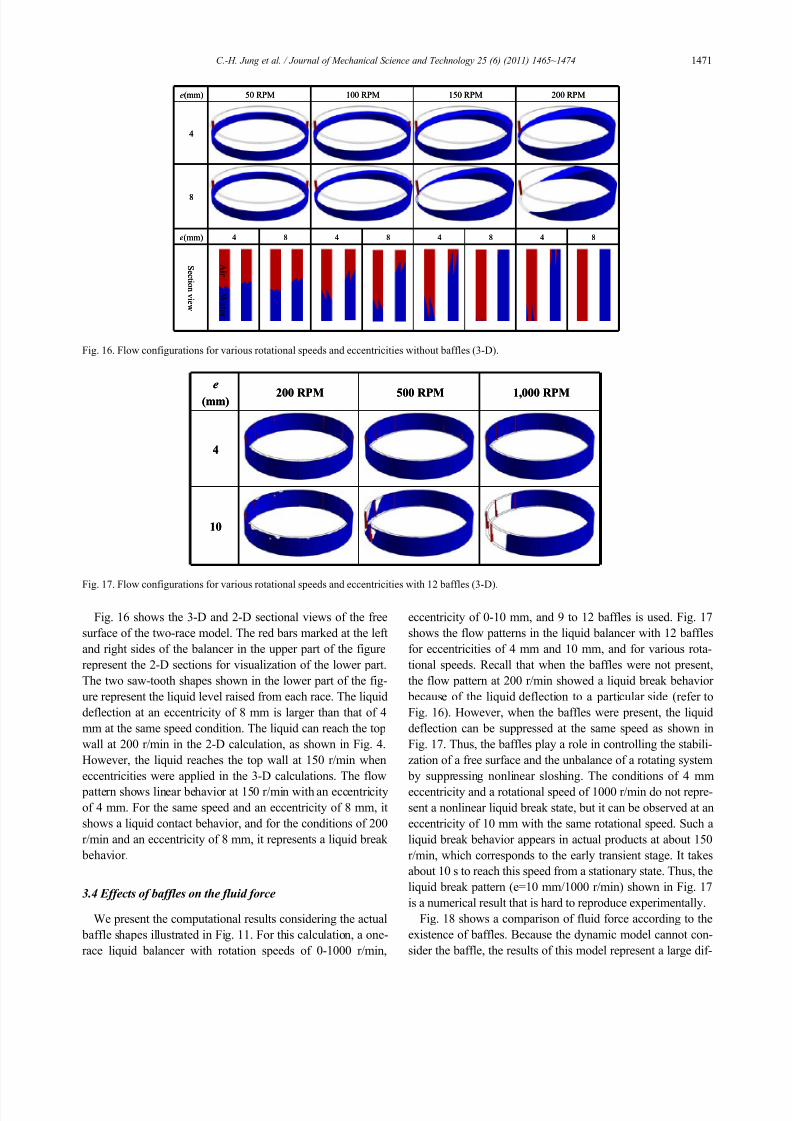
Fig. 16 shows the 3-D and 2-D sectional views of the free
surface of the two-race model. The red bars marked at the left
and right sides of the balancer in the upper part of the figure
represent the 2-D sections for visualization of the lower part.
The two saw-tooth shapes shown in the lower part of the fig-
ure represent the liquid level raised from each race. The liquid
deflection at an eccentricity of 8 mm is larger than that of 4
mm at the same speed condition. The liquid can reach the top
wall at 200 r/min in the 2-D calculation, as shown in Fig. 4.
However, the liquid reaches the top wall at 150 r/min when
eccentricities were applied in the 3-D calculations. The flow
pattern shows linear behavior at 150 r/min with an eccentricity
of 4 mm. For the same speed and an eccentricity of 8 mm, it
shows a liquid contact behavior, and for the conditions of 200
r/min and an eccentricity of 8 mm, it represents a liquid break
behavior.
3.4 Effects of baffles on the fluid force
We present the computational results considering the actual
baffle shapes illustrated in Fig. 11. For this calculation, a one-
race liquid balancer with rotation speeds of 0-1000 r/min,
eccentricity of 0-10 mm, and 9 to 12 baffles is used. Fig. 17
shows the flow patterns in the liquid balancer with 12 baffles
for eccentricities of 4 mm and 10 mm, and for various rota-
tional speeds. Recall that when the baffles were not present,
the flow pattern at 200 r/min showed a liquid break behavior
because of the liquid deflection to a particular side (refer to
Fig. 16). However, when the baffles were present, the liquid
deflection can be suppressed at the same speed as shown in
Fig. 17. Thus, the baffles play a role in controlling the stabili-
zation of a free surface and the unbalance of a rotating system
by suppressing nonlinear sloshing. The conditions of 4 mm
eccentricity and a rotational speed of 1000 r/min do not repre-
sent a nonlinear liquid break state, but it can be observed at an
eccentricity of 10 mm with the same rotational speed. Such a
liquid break behavior appears in actual products at about 150
r/min, which corresponds to the early transient stage. It takes
about 10 s to reach this speed from a stationary state. Thus, the
liquid break pattern (e=10 mm/1000 r/min) shown in Fig. 17
is a numerical result that is hard to reproduce experimentally.
Fig. 18 shows a comparison of fluid force according to the
existence of baffles. Because the dynamic model cannot con-
sider the baffle, the results of this model represent a large dif-
Ai r
W a t e r
Ai r
W a t e r
e(mm) 50 RPM 100 RPM 150 RPM 200 RPM
4
8
e(mm) 4 8 4 8 4 8 4 8
S e c t i on vi e w
e(mm) 50 RPM 100 RPM 150 RPM 200 RPM
4
8
e(mm) 4 8 4 8 4 8 4 8
S e c t i on vi e w
Fig. 16. Flow configurations for various rotational speeds and eccentricities without baffles (3-D).
e
(mm) 200 RPM 500 RPM 1,000 RPM
4
10
e
(mm) 200 RPM 500 RPM 1,000 RPM
4
10
Fig. 17. Flow configurations for various rotational speeds and eccentricities with 12 baffles (3-D).
Page 8
7/30/2019 A Computational Study on the Flow Characteristics of a Self-compensating Liquid Balancer
http://slidepdf.com/reader/full/a-computational-study-on-the-flow-characteristics-of-a-self-compensating-liquid 8/10
1472 C.-H. Jung et al. / Journal of Mechanical Science and Technology 25 (6) (2011) 1465~1474
ference compared to those of the CFD calculations. The baffle
has two functions. One is to prevent excessive liquid deflec-
tion, and the other is to control the sloshing vibration of liquid.
However, as shown in Fig. 18, the fluid force can be signifi-
cantly decreased when baffles are used. Accordingly, it is
necessary to design a system that performs these two functions
optimally without any decrease in the fluid force. Fig. 18
shows that there are no differences in the fluid force at 50
r/min regardless of the existence of baffles. This means that
the baffles play a role in preventing liquid deflection duringthe early stage of rotation. However, there are significant dif-
ferences in the fluid force for rotational speed over 100 r/min
depending on the existence of baffles. Therefore, the number
of baffles should be selected with careful consideration of
these observations.
Figs. 19-22 show a comparison of fluid force according to
the number of baffles for various rotational speeds in a one-
race balancer used for the 7 kg capacity washing machine. Fig.
19 shows fluid forces for 9, 10, and 12 baffles at 50 r/min. It
can be seen that the fluid force increases linearly. In Fig. 20,
the variation of the fluid forces at 100 r/min shows nonlinear
behavior only for 12 baffles. The fluid force at 200 r/min inFig. 21 shows nonlinear behavior for all three types of baffles.
Finally, Fig. 22 shows that the fluid forces at 1000 r/min for 9
and 10 baffles increase steadily, but fluid force for 12 baffles
increases with nonlinear behavior. The nonlinear behaviors in
fluid forces in the above figures occur because the liquid dis-
tribution inside the liquid balancer becomes non-uniform as
the eccentricity increases. In particular, for the case of
e=10mm and r/min=200 in Fig. 17, we can see that the liquid
is confined in the shape of saw tooth. This non-uniform con-
finement of liquid between the baffles and the balancer walls
results in the non-linear fluid forces. These behaviors differ
Fig. 18. Fluid force according to the existence of baffles.
Fig. 19. Fluid force according to the number of baffles at 50 r/min.
0
0.025
0.05
0.075
0.1
0.125
0.15
0.175
0.2
0 2 4 6 8 10
Eccentricity (mm)
F
/ w ^ 2
9 baffles
10 baffles
12 baffles
Fig. 20. Fluid force according to the number of baffles at 100 r/min.
0
0.05
0.1
0.15
0.2
0.25
0.3
0.35
0 2 4 6 8 10
Eccentricity (mm)
F / w ^ 2
9 baffles
10 baffles
12 baffles
Fig. 21. Fluid force according to the number of baffles at 200 r/min.
0
0.1
0.2
0.3
0.4
0.5
0.6
0.7
0.8
0.9
0 2 4 6 8 10
Eccentricity (mm)
F / w ^ 2
9 baffles
10 baffles
12 baffles
Fig. 22. Fluid force according to the number of baffles at 1000 r/min.
Page 9
7/30/2019 A Computational Study on the Flow Characteristics of a Self-compensating Liquid Balancer
http://slidepdf.com/reader/full/a-computational-study-on-the-flow-characteristics-of-a-self-compensating-liquid 9/10
C.-H. Jung et al. / Journal of Mechanical Science and Technology 25 (6) (2011) 1465~1474 1473
according to its magnitude of eccentricity and thus fluid forces
show non-linear behavior such as those in Figs. 18-22. To
summarize, the fluid force versus increase of eccentricity in-
creases linearly at low rotational speed; its nonlinearity is
maximized at intermediate speed; and its variation is stabilized
at high speed. In addition, the magnitude of the fluid force for
12 baffles is relatively smaller than that of the other cases for the entire range of rotational speed. However, the fluid force
shows a steady increase with 9 and 10 baffles.
4. Conclusions
In the present study, a dynamic model and a CFD method
were used to analyze the liquid flow inside a liquid balancer.
The results of this study can be summarized as follows:
(1) The behavior of the free surface was calculated using a
dynamic model and a CFD method for a 2-D model of the
liquid balancer in order to verify the CFD method. The results
obtained from these two methods agree well each other, and
thus the CFD method is acceptable. Also, the maximum risinglevel of the free surface was observed at 200 r/min. In addition,
the level of the free surface decreased slightly at around 100
r/min when the surface tension is considered.
(2) In order to investigate the effects of viscosity on fluid
force, computations were made using water and oil as working
fluids. It was shown that the oil, which has a large viscosity
coefficient, represents a low tangential velocity compared to
that of the water. Computational studies were also made for
the condition of gravity acting in the vertical and horizontal
directions with respect to the balancer itself. When gravity
acts in the horizontal direction, it was found that the tangential
velocity is larger than if gravity acts in the vertical direction.On the contrary, when gravity acts in the vertical direction, the
radial velocity is larger than if gravity acts in the horizontal
direction.
(3) Fluid forces are calculated according to the arrangement
of baffles using 2-D models. If the gap between the baffles
and the outer wall of the balancer is larger than the width of
the balancer by 15%, the baffles do not affect the fluid force,
and the fluid force remains nearly the same as the case without
baffles. This is because the momentum of water is not sup-
pressed by the baffles; rather, it transfers to the inner wall
because the water freely passes through the baffles.
(4) Computational studies were also made to obtain the
fluid force for the liquid balancer without baffles using eccen-
tricity and rotational speed as variables. For a speed of 1000
r/min, it was found that the results obtained by CFD agree
with those of the dynamics model. In addition, if the rotational
speed exceeds 150 r/min, the gradient of the restoration force
becomes large for small eccentricities (e < 6 mm), but it de-
creases significantly for large eccentricities (6 mm < e < 10
mm).
(5) Computational results of the CFD method for the multi-
race liquid balancer showed trends similar to the dynamic
model. A two-race model can be constructed by adding a con-
centric partition wall to a one-race model. The calculations
were performed according to the arrangement of the partition
wall. It is advantageous when increasing the fluid force to
install the partition wall midway between the inner and outer
walls, thereby making the gaps between the inner and outer
walls equal. The flow pattern of the two-race model shows
linear behavior up to the conditions of 150 r/min and eccen-tricity of 4 mm, and a liquid contact behavior at the conditions
of 150 r/min and 8 mm eccentricity. Conditions with the same
speed with eccentricity of 8 mm shows a liquid contact behav-
ior, and for the conditions of 200 r/min and eccentricity of 8
mm, it represents a liquid break behavior. Also, there were no
differences in the fluid forces between the one-race and the
two-race models in the early rotation stage in which the exces-
sive eccentricity (10 mm at its maximum) might occur. This
means that there would be no fluid forces regardless of the use
of the multi-race in the early stage of rotation, where excessive
eccentricity occurs.
(6) The baffle has two functions. One is to prevent exces-
sive liquid deflection, and the other is to control the sloshing
vibration of liquid. A dynamic model cannot consider the
baffle, but the CFD model can. Thus, we performed CFD
calculations for the liquid balancer with baffles. If the baffles
are considered, the fluid force significantly decreases. Also,
there are no significant differences in the fluid force at 50
r/min regardless of the existence of baffles. This means that
the liquid cannot generate a centrifugal force at low rotational
speed. Thus, the tub during the early rotation stage shows an
excessive eccentricity due to unbalanced mass, and this is
aggravated by the deflection of water. Thus, an increase in the
number of baffles is not effective in preventing such phenom-
ena.(7) The one-race balancer used for the 7 kg capacity wash-
ing machine included 12 baffles. The CFD calculations for
this model showed that the fluid force increased nonlinearly
for rotation speeds from 100 to 500 r/min. Also, 12 baffles
represent smaller fluid forces than 9 or 10 baffles under the
same conditions. However, the fluid forces for 9 and 10 baf-
fles show a steady increase for the entire range of rotational
speed.
Acknowledgment
This research was financially supported in part by the Min-
istry of Knowledge Economy (MKE) and Korea Industrial
Technology Foundation (KOTEF) through the Human Re-
source Training Project for Strategic Technology.
Nomenclature------------------------------------------------------------------------
e : Eccentricity (m)
F : Centrifugal force (N)
g : Gravitational acceleration (m/s2)
H : Height of the balancer (m)
m : Mass of water (kg)
Page 10
7/30/2019 A Computational Study on the Flow Characteristics of a Self-compensating Liquid Balancer
http://slidepdf.com/reader/full/a-computational-study-on-the-flow-characteristics-of-a-self-compensating-liquid 10/10
1474 C.-H. Jung et al. / Journal of Mechanical Science and Technology 25 (6) (2011) 1465~1474
Ri, Ro : Inner and outer radius of the balancer (m)
R s : Distance from the rotating axis to the inner surface of
the liquid (m)
V : Liquid volume (m3)
Greek symbols
ρ : Density of the liquid (kg/m3)
ω : Speed of rotation (r/min)
References
[1] C. H. Jung, C. S. Kim and Y. H. Choi, A dynamic model and
numerical study on the liquid balancer used in an automatic
washing machine, Journal of Mechanical Science and Tech-
nology, 22 (2008) 1843-852.
[2] S. Saito and T. Someya, Investigation into the vibration of a
rotating hollow shaft partially filled with liquid (3rd Report,
Calculation of Stability Limit), Transactions of the Japan
Society of Mechanical Engineers. C , 45 (400) (1979) 1325-
331.
[3] S. Saito and T. Someya, Investigation into the vibration of a
rotating hollow shaft partially filled with liquid (1st Report,
Numerical Solution of Liquid Force by the Finite Difference
Method), Transactions of the Japan Society of Mechanical
Engineers, 44 (388) (1978) 4115-4122.
[4] S. Kaneko and S. Hayama, On free surface oscillations of
liquid partially filling a rotating cylinder (2nd Report, The
Calculation of Fluid Force Using Boundary Layer Approxi-
mation), Transactions of the Japan Society of Mechanical
Engineers. C , 49 (439) (1983) 381-391.
[5] S. Kaneko and S. Hayama, On free surface oscillations of liquid partially filling a rotating cylinder (1st Report, Visu-
alization of Resonant Mode and Analysis by Inviscid The-
ory), Transactions of the Japan Society of Mechanical Engi-
neers. C , 49 (439) (1983) 370-380.
[6] B. R. Munson, D. F. Young and T. H. Okiishi, Fundamentals
of fluid mechanics (3rd ed.), New York : John Wiley (1998).
[7] M. Ohkame, The free surface of rotating viscous liquid (VI,
The Invariable Point in Height), The bulletin of the Okayama
College of Science, 12 (1976) 141-148.
[8] M. S. Kim, S. S. Shin and W. I. Lee, A new VOF-based
numerical scheme for the simulation of fluid flow with free
surface (1), Transactions of the KSME B, 24 (12) (2000)
1555-1569.
[9] M. Ohkame, The free surface of rotating viscous liquid (IV,
The Angles of Contact), The bulletin of the Okayama Col-
lege of Science, 10 (1975) 101-109.
[10] M. Ohkame, The free surface of rotating viscous liquid (V,
The Section under the Action of the Surface Tension), The
bulletin of the Okayama College of Science, 11 (1975) 109-
113.[11] S. Saito, T. Someya and M. Kobayashi, Investigation into
the vibration of a hollow shaft partially filled with liquid (4th
Report, Experimental Results), Transactions of the Japan
Society of Mechanical Engineers. C , 48 (427) (1982) 321-
327.
[12] H. Kikura, T. Takehuchi, T. Sawada and T. Tanahashi,
Numerical analysis of nonlinear water waves using arbitrary
lagrangian-eulerian finite element method, Transactions of
the Japan Society of Mechanical Engineers. B, 57 (540)
(1991) 2632-2639.
[13] M. Ohkame, The free surface of a rotating viscous liquid (I),
The bulletin of the Okayama College of Science, 5 (1969)
27-35.
[14] S. Saito, Investigation into the vibration of a hollow shaft
partially filled with liquid (5th Report, Approximate Solu-
tion of the Liquid Force Using Boundary Layer Theory),
Transactions of the Japan Society of Mechanical Engineers.
C , 48 (429) (1982) 656-661.
[15] Y. Yamada and S. Imao, Flow of a fluid contained concen-
tric cylinders both rotating, Bulletin of JSME , 29 (252)
(1986) 1691-1697.
[16] J. R. Cho and H. W. Lee, Numerical study on liquid slosh-
ing in baffled tank by nonlinear finite element method, Com-
puter methods in applied mechanics and engineering , 193
(2004) 2581-2598.
Chung-Hyo Jung acquired the doctoral
degree in the Dept. of Science for Open
and Environmental Systems at Keio
University in 2003. The specialty in the
doctoral course was GSMAC-FEM and
studied on MHD (magnetohydrodynam-
ics). Dr. Jung joined Samsung Elec-
tronics Co., Ltd. as a CFD engineer in
2003. Also, he has worked at Samsung Advanced Institute of
Technology and has charged in the thermal analysis of semi-
conductors (system LSI). One of the Dr. Jung's major con-
cerning fields is the mechanical application of Lie-Groups.


![Compensating Teams[1]](https://static.documents.pub/doc/80x56/577d27c61a28ab4e1ea4cb06/compensating-teams1.jpg)


