32
® MAKE IT SIMPLE A Conical Connection Implant

MC
-UN
O08 R
ev.1M
C-U
NO
08 Rev.1
®
M A K E I T S I M P L E
A Conical Connection Implant
MC
-CO
NE
N R
ev.13

MIS Warranty:
MIS exercises great care and effort in maintaining the superior quality of its products. All MIS products are guaranteed to be free from defects in material and workmanship. However, should a customer find fault with any MIS product after using it according to the directions, the defective product will be replaced.
Warning: Products should be used by licensed dentists only.
P.17-19
P.20-21
P.22-23
P.26-27
P.15-16
P.12-14
P.10-11
P.8-9
P.6-7
P.4-5
P.24-25
P.28
P.29

Table of contents.
Introduction
Advantages
Surface Quality
Narrow Implants (Ø3.30mm)
Standard Implants (Ø3.75mm, Ø4.20mm)
Wide Implants (Ø5mm)
C1 Surgical Kit
Drilling Procedures
Dual Stability Mechanism
Drill Stopper Kits
Insertion Tools
Package Contents
Packaging

4.
© MIS Corporation. All rights reserved.
The C1 implant system is an advanced implant design
that offers a unique combination of surgical and restorative
benefits, including a differential thread design to ensure
superior initial stability in different clinical situations, platform
switching and a conical connection with an anti-rotation
index. Each C1 implant comes with a single-use final drill
to ensure a safer and more accurate drilling procedure.


Advantages.
6.
C1 Conical connection implants
All C1 implants, superstructures and tools are color-coded for simple and immediate identification of the platform size.
Advantages.
Greenindicates a Wide platform
Purpleindicates a Standard platform
Yellow indicates a Narrow platform

Conical connectionFeaturing a 6-degree conical connection that ensures a secure fit between abutment and implant, the C1 minimizes micro-movements reducing bone loss at the crestal level. It has is a six-position cone index within the conical connection to help orient the implant during insertion as well as placing the abutment into the proper position.
Prosthetic optionsA broad range of MIS conical connection prosthetic components presents uncompromising accuracy; a consistent concave emergence profile for excellent soft tissue results; golden shade to support high esthetic results; color coding for simple and immediate platform identification and a positioning groove ensures definite fit over the implant.
Conical shapeWith its conical, root-shaped geometry and a unique thread design, C1 ensures a superior primary stability and offers the ultimate choice for a wide range of clinical cases and loading protocols ▪ Its root-shaped design makes C1 ideal for narrow spaces, restricted by adjacent teeth or implants.
Two spiral channels and domed apexThe C1 features a domed apex, providing a high tolerance and safe procedure during insertion. Two cutting blades at the implant apex establish the self-tapping properties of the C1; supporting a simpler, safer and faster procedure.
Platform switchingThe C1 platform switching keeps the implant-abutment connection away from the bone; minimizing bone resorption. Platform switching additionally allows more vital growth of the soft tissue.
Micro-ringsAt the neck of the C1, micro-rings significantly increase the BIC (Bone to Implant Contact), avoiding bone resorption at the crestal zone.
Dual threadThe C1 dual thread design increases the BIC (Bone to Implant Contact) over the entire body of the implant. The dual thread doubles the implant insertion rate (1.50mm), facilitating a simpler and faster implant placement.

Advantages.
8.
Surface Quality.
C1 implants are sand-blasted and acid-etched. These surface treatments increase the implant surface area by creating both micro and nano-structures and eliminating various surface contaminants. The surface of MIS implants was found superior in its purity compared to other implant systems by two independent researches, as published in the POSEIDO Journal and in EDI Journal.

2015/1
SURFACE ANALYSIS OF STERILE-PACKAGED IMPLANTSDr. Dirk Duddeck and Dr. Jörg Neugebauer, PhD
For the third time in a row, the Quality and Research (Q&R) Committee of BDIZ EDI is examining sterilepackaged implants under the scanning electron microscope for the more than 5,500 members of the association. In cooperation with the University Hospital of Cologne, extensive qualitative and quantitative elemental analyses are performed on each of the implants studied. In 2009/2008, the surfaces of 23 implants were analyzed, a number that had grown to 54 different implants from manufacturers in nine countries by 2012/2011. Here, isolated implants showed residue from the manufacturing and/or packaging process, pecularities in the external threading or residual filings inside the implant.
Conclusions reached in the study state:
"The C1 implant and the Seven implant (both MIS) stood out positively in the current study. Whereas during the 2012/2011 study, the Seven implant still exhibited blasting material on up to seven per cent of the surface, the current study did not even find isolated spots with residue on the two MIS implant types of grade 23 titanium (Ti 6Al4-V ELI)".
65 dental implants from different leading manufacturers underwent topographical and chemical composition analysis. The protocol included the use of a Scanning Electron Microscope (SEM), which enabled the topical evaluation of each implant surface. The high sensitivity backscattered electron detector generates images in compositional and topographical modes to a magnification of up to X5,000 for this study. The BSE detector also allows researchers to draw conclusions about the chemical nature and allocation of remnants or contaminants on the sample material. Qualitative and quantitative analyses of implant surfaces were done using Energy Dispersive X-ray Spectroscopy (EDX). This element identification software even allows the identification of elements deep within the sample. Testing on MIS implants revealed percentages of Titanium, Oxygen, Aluminum and Vanadium.
Residue-free surface, MIS C1 implant (x 1000). MIS C1 implant surface with micro-nano-structure (x 2,500). MIS C1 implant side-view of a thread (x 2,000).
The study is available for download from the MIS Website: Surface Analysis of Sterile-Packaged Implants: EDI Journal, Issue 2015/1:http://www.mis-implants.com/Scientific/Articles.aspx
16mm11.50mm 13mm10mm
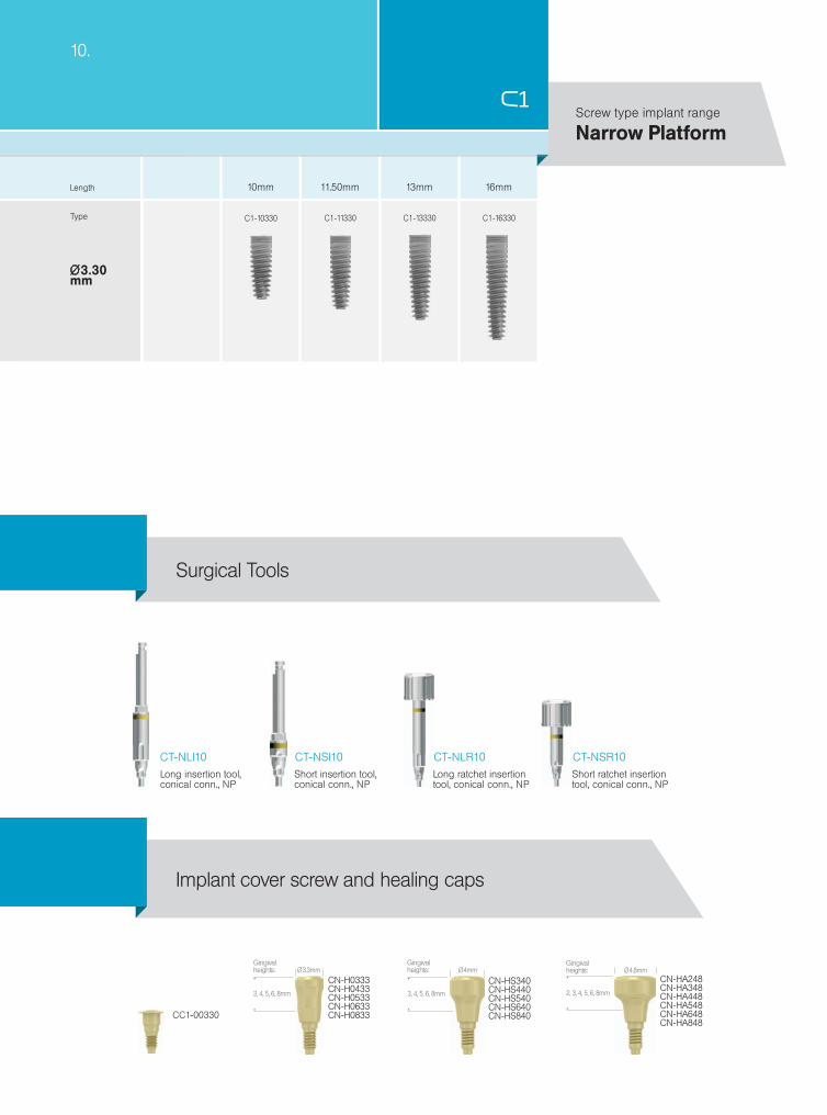
Ø3.30mm
10.
C1-10330 C1-13330 C1-16330C1-11330
CT-NLI10 CT-NSI10 CT-NLR10 CT-NSR10
CC1-00330
CN-H0333CN-H0433CN-H0533CN-H0633CN-H0833
Ø 3.3mm
3, 4, 5, 6, 8mm
CN-HS340CN-HS440CN-HS540CN-HS640CN-HS840
Ø 4mm
3, 4, 5, 6, 8mm
CN-HA248CN-HA348CN-HA448CN-HA548CN-HA648CN-HA848
Ø 4.8mm
2, 3, 4, 5, 6, 8mm
Narrow PlatformScrew type implant range
Length
Type
Implant cover screw and healing caps
Long insertion tool,conical conn., NP
Short insertion tool,conical conn., NP
Long ratchet insertiontool, conical conn., NP
Short ratchet insertiontool, conical conn., NP
Surgical Tools
Gingival heights:
Gingival heights:
Gingival heights:
Ø 2.50
Ø 3.30
Ø2.4
Ø 3.2
Ø2.75
1200-1500
900-1200
Ø1.90 Ø3.30Ø2.40 Ø2.40
15-25Ø3 Ø3.60
200-400
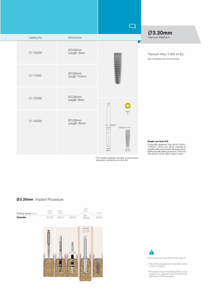
C1-10330
C1-11330
C1-13330
C1-16330
Ø3.30mm
Ø3.30mm
Ø 3.30mm
Ø 3.30mm
Ø 3.30mm
Ø 3.30mm
Catalog No. Dimensions
Length 10mm
Length 11.5mm
Length 16mm
Length 13mm
Single-use final drill A specially designed final drill for 10mm, 11.50mm, 13mm and 16mm implants is supplied with every implant, allowing a short, sterile and safe drilling procedure. This final drill should not be used in type 4 bone.
* The implant package includes: a cover screw, temporary cylinder and a final drill
Titanium Alloy Ti 6Al 4V ELISand-Blasted and Acid-Etched
Narrow Platform
Drilling Speed (RPM)
Diameter
Final drill For bonetype 1,2&3
Implant Procedure
The drilling sequence is illustrated using a 13mm implant.
Procedure recommended by MIS cannot replace the judgment and professional experience of the surgeon.
Do not use the final drill for bone type 4

12.
C1-10375 C1-13375 C1-16375
C1-10420 C1-11420 C1-13420 C1-16420
C1-11375C1-08375
C1-08420
16mm11.50mm 13mm8mm 10mm
Ø3.75mm
Ø4.20mm
CT-SLI10 CT-SSI10 CT-SLR10 CT-SSR10
CC1-00375
CS-H0339CS-H0439CS-H0539CS-H0639CS-H0839
Ø 3.9mm
3, 4, 5, 6, 8mm
CS-HS248CS-HS348CS-HS448CS-HS548CS-HS648CS-HS848
Ø 4.8mm
2, 3, 4, 5, 6, 8mm
VS-HS358VS-HS458VS-HS558VS-HS658VS-HS858
Ø 5.8mm
3, 4, 5, 6, 8mm
Implant cover screw and healing caps
Surgical Tools
Standard PlatformScrew type implant range
Length
Type
Gingival heights:
Gingival heights:
Gingival heights:
Long insertion tool,conical conn., SP
Short insertion tool,conical conn., SP
Long ratchet insertiontool, conical conn., SP
Short ratchet insertiontool, conical conn., SP

Ø 3.10
Ø 3.75
Ø3
Ø 3.60
Ø3.15
C1-08375
C1-16375
C1-10375
C1-11375
C1-13375
Ø3.75mm
Ø 3.75mm
Ø 3.75mm
Ø 3.75mm
Ø 3.75mm
Ø 3.75mm
1200-1500
900-1200
Ø1.90 Ø3 Ø3.75Ø2.40 Ø2.40
500-700 15-25
Ø3 Ø3.60
200-400
Ø3
Ø3.75mm
Single-use final drill A specially designed final drill for 8mm, 10mm, 11.50mm, 13mm and 16mm implants is supplied with every implant, allowing a short, sterile and safe drilling procedure. This final drill should not be used in type 4 bone.
Standard PlatformCatalog No. Dimensions
Length 8mm
Length 10mm
Length 13mm
Length 16mm
* The implant package includes: a cover screw, temporary cylinder and a final drill
The drilling sequence is illustrated using a 13mm implant.
Procedure recommended by MIS cannot replace the judgment and professional experience of the surgeon.
Do not use the final drill for bone type 4
Titanium Alloy Ti 6Al 4V ELISand-Blasted and Acid-Etched
Implant Procedure
Drilling Speed (RPM)
Diameter
For bonetype 1,2&3
Final drill
Length 11.50mm

Ø4.20mm
Ø3.50
Ø4
Ø 3.60
Ø 4.20
Ø3.15
C1-08420
C1-16420
C1-10420
C1-11420
C1-13420
Ø 4.20mm
Ø 4.20mm
Ø 4.20mm
Ø 4.20mm
Ø 4.20mm
14.
Ø4.20mm
1200-1500
900-1200
Ø2.40 Ø3Ø1.90 Ø2.40
500-700
Ø3.50 Ø3.50
400-700
Ø3.50Ø4
200-400
Ø4.20
15-25Drilling Speed (RPM)
Diameter
For bonetype 1,2&3
Final drill
Implant Procedure
Titanium Alloy Ti 6Al 4V ELISand-Blasted and Acid-Etched
Standard Platform
Single-use final drill A specially designed final drill for 8mm, 10mm, 11.50mm, 13mm and 16mm implants is supplied with every implant, allowing a short, sterile and safe drilling procedure. This final drill should not be used in type 4 bone.
The drilling sequence is illustrated using a 13mm implant.
Procedure recommended by MIS cannot replace the judgment and professional experience of the surgeon.
Do not use the final drill for bone type 4
* The implant package includes: a cover screw, temporary cylinder and a final drill
Catalog No. Dimensions
Length 8mm
Length 10mm
Length 13mm
Length 16mm
Length 11.50mm

16mm11.50mm 13mm8mm 10mm
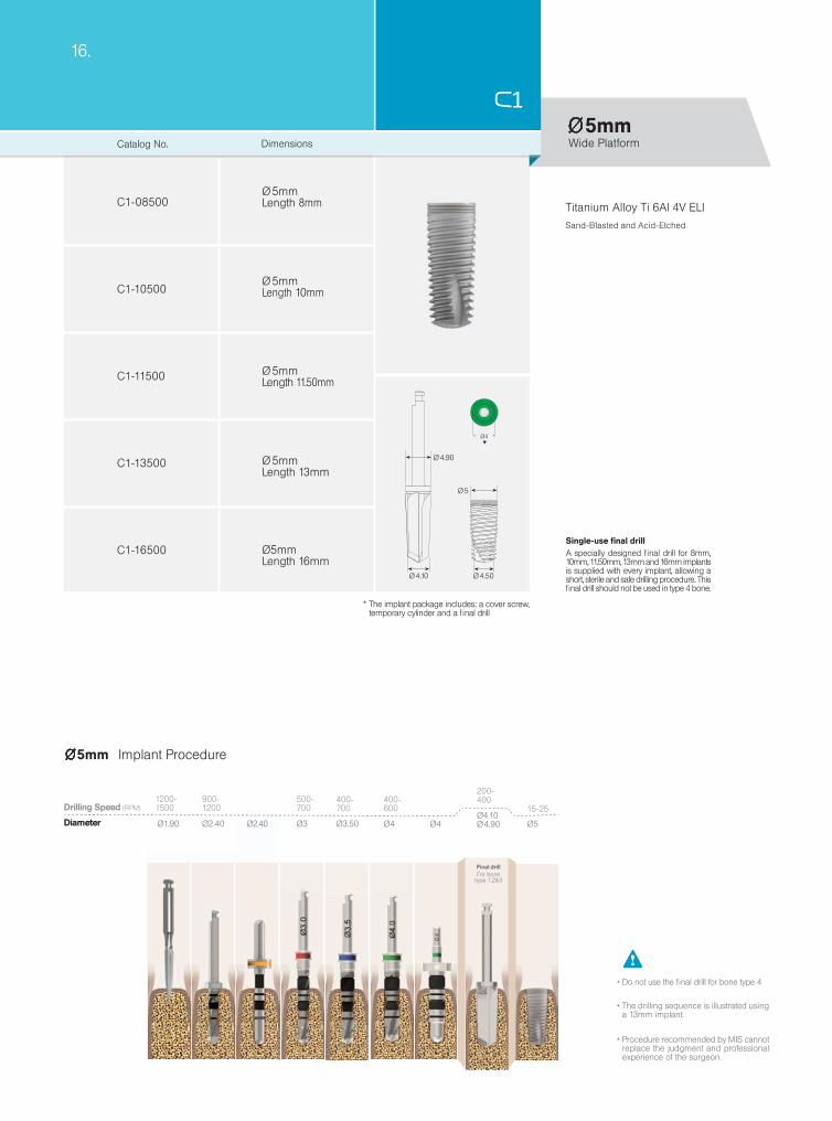
Ø5mm
C1-08500 C1-10500 C1-11500 C1-13500 C1-16500
CT-WLI10 CT-WSI10 CT-WLR10 CT-WSR10
CC1-00500
CW-HS355CW-HS455CW-HS555CW-HS655
CW-HS355CW-HS455CW-HS555CW-HS655
Ø 5.5mm
3, 4, 5, 6mm
CW-HA263CW-HA363CW-HA563
Ø6.3mm
2, 3, 5mm
Length
Type
Wide PlatformScrew type implant range
Implant cover screw and healing caps
Surgical Tools
Long insertion tool,conical conn., WP
Short insertion tool,conical conn., WP
Long ratchet insertiontool, conical conn., WP
Short ratchet insertiontool, conical conn., WP
Gingival heights:
Gingival heights:
Ø5mm
C1-08500
C1-16500
C1-10500
C1-11500
C1-13500
Ø 5
Ø 4.50Ø 4.10
Ø 4.90
Ø4
Ø 5mm
Ø 5mm
Ø 5mm
Ø5mm
Ø 5mm
Ø4.10 Ø 4.90
200-400
Ø5
15-25
Ø4
400-600
1200-1500
900-1200
Ø2.40 Ø3 Ø3.50Ø2.40Ø1.90
500-700
400-700
Ø5mm
Ø4
16.
Drilling Speed (RPM)
For bonetype 1,2&3
Final drill
Implant Procedure
Wide Platform
Single-use final drill A specially designed final drill for 8mm, 10mm, 11.50mm, 13mm and 16mm implants is supplied with every implant, allowing a short, sterile and safe drilling procedure. This final drill should not be used in type 4 bone.
The drilling sequence is illustrated using a 13mm implant.
Procedure recommended by MIS cannot replace the judgment and professional experience of the surgeon.
Do not use the final drill for bone type 4
Titanium Alloy Ti 6Al 4V ELISand-Blasted and Acid-Etched
* The implant package includes: a cover screw, temporary cylinder and a final drill
Catalog No. Dimensions
Length 8mm
Length 10mm
Length 13mm
Length 16mm
Length 11.50mm
Diameter

C1 Surgical Kit
The C1 surgical kit comprises a complete range of drills and tools required for C1 implant placement procedures. It features a convenient ergonomic layout that follows the surgical drilling sequence, and includes a set of length-based pilot drills for a smoother, more accurate procedure. Kit components are color-coded for immediate identification of diameters for both implants and restorative platforms.

18.
MK-0044
32
12
13
14
3
5
4
26
27
20
25
21
24
35
36
8
9
10
23
22
1
7
CT-P2416
4
CT-P2410
5
CT-P2411
6
CT-P2413
3
CT-P2408 CT-BTC24
12
CT-BTC30
13
CT-BTC40
15
CT-BTC45
16
14
CT-BTC35
8
CT-TDC30
9
CT-TDC35
10
CT-TDC40
11
CT-TDC45
MT-SMD10
2
1
MT-TDN19
MARKING DRILLS PILOT DRILLS BODY TRY-INSSTEP DRILLS
Pilot drill, Ø2.4/2.0mm, height 16mm
Pilot drill with built-in stopper Ø2.4/2.0mm, height 10mm
Pilot drill with built-in stopper Ø2.4/2.0mm, height 11.5mm
Pilot drill with built-in stopper, Ø2.4/2.0mm, height 13mm
Pilot drill with built-in stopper Ø2.4/2.0mm, height 8mm
Body try-in, Ø2.40mm
Body try-in, Ø3mm
Body try-in, Ø4mm
Body try-in, Ø4.5mm
Body try-in, Ø3.50mm
Step drill, Ø3/2.4mm, external irrigation
Step drill, Ø3.5/3mm, external irrigation
Step drill, Ø4/3.5mm, external irrigation
Step drill, Ø4.5/4mm, external irrigation
With external irrigation drills
C1 Surgical Kit
Spade marking drill
Marking drill, Ø1.90mm external irrigation

18
17
19
15
16
2
5
6
7
30
31
28
33
37 38
10
11
34
29
MT-GDN33
18
Countersink, NP
17
19
MT-GDN50
MT-PP240
32
MT-DE001MT-DE001
33
MT-RE160
35
MT-RDL30
37
38
MT-RDS30
36
MT-RE172
34
MT-RT070
20
CT-NSR10
21
CT-NLR10CT-NLR10
CT-SSR10
24
23
CT-NLI10
22
CT-NSI10
26
CT-SSI10
30
CT-WSI10
27
CT-SLI10
31
CT-WLI10
28
CT-WSR10
25
CT-SLR10
29
CT-WLR10
INSERTION TOOLSCOUNTERSINKS
Countersink, SP
MT-CSN33
Countersink, WP
Parallel pin, Ø2.40/3mm
Drill extender
Int. connection abutment extractor, NP
Long hex. drive for 0.05 inch
Short hex. drive for 0.05 inch
Int. connection abutment extractor, SP
Torque Ratchet for implant placement
SURGICAL TOOLS
Short ratchet insertion tool, conical conn., NP
Long ratchet insertion tool, conical conn., NP
Short ratchet insertion tool, conical conn., SP
Long insertion tool, conical conn., NP
Short insertion tool, conical conn., NP
Short insertion tool, conical conn., SP
Short insertion tool, conical conn., WP
Long insertion tool, conical conn., SP
Long insertion tool, conical conn., WP
Short ratchet insertion tool,conical conn., WP
Long ratchet insertion tool, conical conn., SP
Long ratchet insertion tool, conical conn., WP
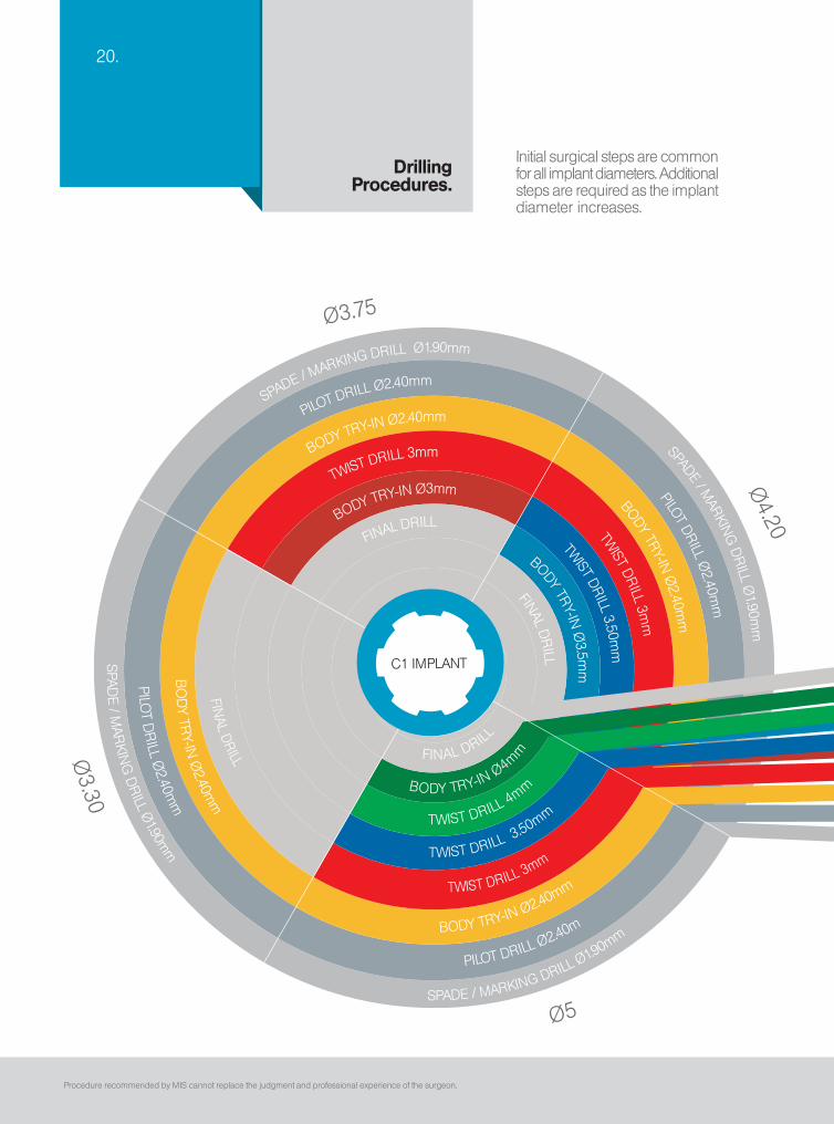
Ø3.75
Ø3.30
Ø4.20
Ø5
SPADE / M
ARKING DRILL Ø1.90mm SPADE / MARKIN
G D
RILL Ø
1.90mm
PILOT DRILL Ø2.40mm PILOT DR
ILL Ø2.40m
m
BODY TRY-IN Ø2.40mm BODY TRY-IN Ø
2.40mm
TWIST DRILL 3mm TW
IST DRILL 3m
m
B
ODY TRY-IN Ø3mm TWIST DR
ILL 3.50mm
FINAL DRILL BODY TRY-IN Ø
3.5mm
FINAL DR
ILL
TWIST DRILL 3.50mm
FINAL DRILL
TWIST DRILL 4mm
FINAL D
RILL TWIST DRILL 3mm
BO
DY TR
Y-IN Ø
2.40mm
BODY TRY-IN Ø2.40mm
PILOT D
RILL Ø
2.40mm
PILOT DRILL Ø2.40m
SPAD
E / MAR
KING
DR
ILL Ø1.90m
m SPADE / MARKING DRILL
Ø1.90mm
BODY TRY-IN Ø4m
m
C1 IMPLANT
20.
Procedure recommended by MIS cannot replace the judgment and professional experience of the surgeon.
Initial surgical steps are common for all implant diameters. Additional steps are required as the implant diameter increases.
DrillingProcedures.
Ø3.75
Ø3.30
Ø4.20
Ø5
SPADE / M
ARKING DRILL Ø1.90mm SPADE / MARKIN
G D
RILL Ø
1.90mm
PILOT DRILL Ø2.40mm PILOT DR
ILL Ø2.40m
m
BODY TRY-IN Ø2.40mm BODY TRY-IN Ø
2.40mm
TWIST DRILL 3mm TW
IST DRILL 3m
m
B
ODY TRY-IN Ø3mm TWIST DR
ILL 3.50mm
FINAL DRILL BODY TRY-IN Ø
3.5mm
FINAL DR
ILL
TWIST DRILL 3.50mm
FINAL DRILL
TWIST DRILL 4mm
FINAL D
RILL TWIST DRILL 3mm
BO
DY TR
Y-IN Ø
2.40mm
BODY TRY-IN Ø2.40mm
PILOT D
RILL Ø
2.40mm
PILOT DRILL Ø2.40m
SPAD
E / MAR
KING
DR
ILL Ø1.90m
m SPADE / MARKING DRILL
Ø1.90mm
BODY TRY-IN Ø4m
m
C1 IMPLANT
Ø1.90 Ø2.40 Ø3Ø2.40 Ø3 Ø3.50 Ø4Ø4Ø3.50
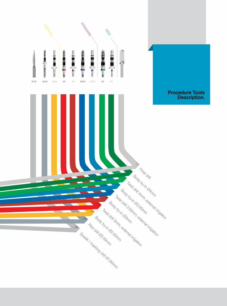
Procedure Tools Description.
Spade / marking drill Ø1.90mm
Body try-in Ø2.40mm
Body try-in Ø3mm
Twist drill 3mm, external irrigation
Twist drill 3.50mm, external irrigation
Twist drill 4mm, external irrigation
Final drill
Body try-in Ø3.50mm
Body try-in Ø4mm
Pilot drill Ø2.40mm
STANDARD
NARROW
WIDE

13.
MECHANICAL STABILITY BIOLOGICAL STABILITY
Thanks to a unique drilling methodology,
the implant's geometric design enables a moderate compression of the bone at the top 2/3 of its body. This congestion, enabled by a distinctive conical shaped final drill, provides an immediate and
prolonged mechanical primary stability.
A n e n h a n c e d secondary biological stability
is achieved by integration of the implant's geometry, morphology and
a differential drilling approach. The compartments formed between the implant's threads at the bottom 1/3 of the cavity, generate an ideal habitat
for sustainable bone growth leading to an accelerated
osseointegration.
22.The Dual Stability Mechanism
The C1 offers a Dual Stability Mechanism (DSM) that combines the benefits of high primary stability with an accelerated osseointegration process, thus minimizing stability loss during the first weeks after
surgery. This differential drilling method enables moderate compression of the bone at the top 2/3 of the implant body in order to gain mechanical stability, while preventing such compression at the apical 1/3.
Thanks to a unique drilling methodology, the implant's
geometric design enables a moderate compression of the bone at the top 2/3 of the body. This compression, enabled by a distinctive conical shaped final drill,
provides an immediate and prolonged mechanical primary stability.

MECHANICAL STABILITY BIOLOGICAL STABILITY
Thanks to a unique drilling methodology,
the implant's geometric design enables a moderate compression of the bone at the top 2/3 of its body. This congestion, enabled by a distinctive conical shaped final drill, provides an immediate and
prolonged mechanical primary stability.
A n e n h a n c e d secondary biological stability
is achieved by integration of the implant's geometry, morphology and
a differential drilling approach. The compartments formed between the implant's threads at the bottom 1/3 of the cavity, generate an ideal habitat
for sustainable bone growth leading to an accelerated
osseointegration.
The 'compartments' created between the threads at the apical 1/3 are filled with blood and bone particles, enabling rapid bone growth.
An enhanced secondary biological stability is achieved by
integration of the implant's geometry, morphology and a differential drilling approach. The compartments formed between the implant's threads at the bottom 1/3 of the cavity generate an ideal habitat for sustainable bone growth leading
to accelerated osseointegration.

24.
MK-BC101
Stoppers
Four sleeves for each diameter in 8, 10, 11.5 and 13mm lengths, color-coded according to drills.
BoxThe tray can be removed from the box for ease of use.
Scale
Teflon OUT Insert
Teflon IN Insert
Simple.
Quick, easy assembly.
Kit Contents Ø3 stoppers(for Ø3.75mm implants)
Ø3.50 stoppers(for Ø4.20mm implants)
Easy.Color-coding for quick identification of the sleeve diameter.
Safe. Safe drilling to desired depth.
Fast.Clearly arranged depth sleeves for quick and easy identification of 8-13mm lengths and Ø3, Ø3.5mm diameter stoppers.
Following the use of MIS length-based pilot drills, the C1 Standard Platform Stoppers Kit ensures drilling to the exact desired depth. The kit includes the most commonly used lengths: 8, 10, 11.5 and 13mm.
Drill Stoppers Kit Standard Platform.

8mm10mm
11.5mm13mm
MK-CDS08 MK-CDS10
MK-CDS11 MK-CDS13
Simple.
Quick, easy assembly.
For 8mm implants For 10mm implants
For 11.5mm implants For 13mm implants
Kit Contents
Scale
Box
Stoppers
The tray can be removed from the box for ease of use.
Five sleeves 3.0, 3.5, 4, 4.5 and 5mm diameters, color-coded according to drills.
Desireddrilling depth
Teflon OUT Insert
Teflon IN Insert
Easy.Color coding for a quick identification of sleeve diameter.
Safe. Safe drilling to desired depth.
Fast.Clearly arranged depth sleeves for quick and easy identification of Ø3mm to Ø5mm diameter drills.
Following the use of MIS length-based pilot drills, the C1 Drill Stoppers Kit enables safe and easy drilling to the exact desired depth. MIS offers 4 different kits in lengths of: 8, 10, 11.5 and 13mm.
Drill Stoppers Kit Depth Based.

22.20.26.
MT-RDL30
MT-RDS30CT-SLI10
CT-SSI10
CT-SLR10
CT-SSR10
C1 implant placement tools are specially designed to facilitate quick and reliable implant procedures.
Insertion Tools.Standard platform tools shown
Long
driv
e fo
r 0.
05 in
ch h
ex.
Sho
rt d
rive
for
0.05
inch
hex
.
Long
inse
rtio
n to
ol, S
P
Sho
rt in
sert
ion
tool
, SP Lo
ng r
atch
et in
sert
ion
tool
, SP
Sho
rt r
atch
et in
sert
ion
tool
, SP

20.
1
2
3
1
2
3
Please note: In order to assure their efficient operation, tools should be fully inserted into the implants. A complete insertion of the tool optimizes the transfer of force during implant placement and enables simple release of the tool from the hex. whenever necessary.
Tool will not hold implant unless it is completely inserted into the hex.
MIS offers a line of specially engineered insertion tools suitable for use either manually or with the unique insertion tool system, which allows secure implant placement without the use of a mount, effectively reducing the number of tools required in the armamentarium.
Insertion tool in manual use
Insertion tool for motor
Insertion tool in ratchet wrench
Insertion options:

28.
Each C1 implant comes with sterilized components for multiple clinical scenarios.
Package Contents.
Cov
er S
crew
Fina
l Dril
l
Inne
r Tub
e
Out
er T
ube
Impl
ant
Tem
pora
ry C
ylin
der
Following the "Make It Simple" philosophy, MIS is proud to be the first to present a comprehensive tool set which includes: a single-use final drill, a cover screw and a temporary cylinder with every C1 implant, meeting all your clinical needs.

12.
Packaging.
Easy pull tab
Implant identification markings
The convenient pull tab facilitates quick and easy opening during surgery.
Quick identification of implant size and length. Sticker on the box lid, specifies implant diameter, length and platform size.
Providing a simple, immediate identification of implant type, length and diameter, the C1 package is well designed for ease of use during surgery.
A double packing system ensures sterilization and safety. Packages are designed for ease of use during surgery and for use with surgical gloves.
Implant diameter & platform indicationThe outer tube is color-coded indicating the implant platform. The numeric indication specifies the implant diameter and length.
Prosthetic platform indicationProsthetic components are marked by specific colors, representing platform sizes.


® All rights reserved. No part of this publication may be reproduced, transcribed, stored in an electronic retrieval system, translated into any language or computer language, or be transmitted in any form whatsoever, without the prior written consent of the publisher.

Authorized European Representative:MIS Germany, Paulinenstraße 12a, 32427 Minden, GERMANY
0483
© MIS Corporation. All Rights Reserved.
MIS Implants Technologies Ltdwww.mis-implants.com
MC
-UN
O08 R
ev.1M
C-U
NO
08 Rev.1
© MIS Corporation. All rights reserved.
The MIS Quality System complies with international
quality standards: ISO 13485:2003 - Quality
Management System for Medical Devices, ISO
9001: 2008 - Quality Management System and
CE Directive for Medical Devices 93/42/EEC. MIS
products are cleared for marketing in the USA
and CE approved.MIS Implants Technologies Ltd.www.mis-implants.com
®
MC
-CO
NE
N R
ev.13


