IEEE TRANSACTIONS ON INFORMATION THEORY, VOL. 60, NO. 1, JANUARY 2014 237
A Contention-Free Parallel Access by ButterflyNetworks for Turbo Interleavers
Esko Nieminen
Abstract— A theoretical foundation for any turbo interleaverto be a contention-free interleaver to access data in parallelby a butterfly network is presented. A contention-free parallelaccess of multiple memories in parallel plays a crucial rolefor implementing high speed turbo decoders for high data rateapplications. The presented theoretical analysis shows that abutterfly network has a sufficiently rich permutation structureto be a routing network between parallel decoder units andmultiple memories. Thus turbo code design is independent ofthe designing of a contention-free parallel access by butterflynetworks. In particular, a turbo interleaver needs not to providea built-in contention-free parallel access for any parallel access bybutterfly networks. We demonstrate how to apply this theory toturbo interleavers widely used in commercial telecommunicationstandards.
AMOTIVATION to apply butterfly networks to parallelaccess turbo decoders stems from the fact that butterfly
networks have a long history as routing networks in variousapplications [1]– [6]. Butterfly networks have a simple recur-sive structure which results in a more economical implemen-tation in terms of an area and a gate count than those of othernetworks. In [6] butterfly networks are used to route extrinsicvalues between a turbo decoder (actually, processors to decodea turbo code) and memories. A single router element of abutterfly network in [6] is not a double-pole double throwswitch (a mere 2-by-2 crossbar switch) but has a complexinternal structure to maintain a contention-free parallel access.Instead in this paper a butterfly network of 2-by-2 crossbarswitches as in [1]–[5] are applied to route extrinsic valuesbetween parallel decoder units and memories. A double-poledouble throw switch, also known as a 2-by-2 crossbar switch,is a switch which is able to connect two input pins eitherdirectly or cross to two output pins; Fig. 1(a).
Lack of parallel processing of a turbo decoder stems from aturbo interleaver which may not be contention-free by default.This is a limiting factor when applying turbo codes for highspeed data communications. There are two main approachesto increase the degree of parallel processing of turbo decoders:
Manuscript received September 7, 2012; revised August 28, 2013; acceptedOctober 14, 2013. Date of publication November 1, 2013; date of currentversion December 20, 2013.
The author is with Broadcom, Oulu 90590, Finland (e-mail:[email protected]).
Communicated by D. Burshtein, Associate Editor for Coding Techniques.Digital Object Identifier 10.1109/TIT.2013.2288339
either to design turbo interleavers such that they supportexplicitly some parallel processing scheme or to solve parallelaccess collisions for a given turbo interleaver.
The interleaver design approach is not a feasible solutionto speed up the existing communication systems. Anotherobvious limitation is that the type of parallel processingcannot be modified afterwards. However, it has been appliedsuccessfully to new communication systems. Almost regularinterleavers, [7]–[9], can be designed such that a degree ofa parallel processing is high. Also the performance of turbocodes with the almost regular permutations is good. Quadraticpermutation polynomials [10], [11] belong to another class ofinterleavers for turbo codes that supports a parallel processingby design. The third example of the design approach could be aspecial class of interleavers with a predefined parallel process-ing capability [12], [13]. For further information on the designapproach and related topics, see [14] and references there.
The methods of [6] and [15]–[17] belong to the solvingof parallel access contentions approach. The type of paral-lel processing can be chosen independently of the choiceof turbo interleavers. These methods do not modify turbointerleavers and they can be applied to both existing andfuture communication systems. Theoretical analysis presentedin [15]–[17] does not guarantee that a contention-free parallelaccess can be achieved by using a butterfly network of2-by-2 crossbar switches as an interconnection networkbetween a turbo decoder and memories. The focus of thispaper is to provide a theoretical analysis of any turbo inter-leaver to be contention-free for a parallel access by a butterflynetwork.
An interval of integers from 0 to x − 1 is denoted by Wx
for an integer x ≥ 1. A turbo interleaver of a length N froman address space WN to itself is denoted by T and its inverseby T −1. An inverse of an interleaver is called a de-interleaver.A degree of a parallel processing is n and n ≥ 2. In this paperwe assume that N is a multiple of 2m , that is, 2m is a factorof N .
Due to the general structure of turbo codes a parallel accessof extrinsic values is executed either in a linear order or in
238 IEEE TRANSACTIONS ON INFORMATION THEORY, VOL. 60, NO. 1, JANUARY 2014
an interleaved order at a time. A multiple access scheme isdenoted by A and it determines which extrinsic values ofa turbo code are accessed in parallel at a time in the twodifferent access orders. The linear order parallel access ofthe multiple access scheme A is a vector valued functionAL defined by AL(k) = (a0(k), a1(k), a2(k), . . . , an−1(k)) forall k in WN/n , where each component a j (k) is a functionfrom the index space WN/n to the address space WN . Itis assumed that the values of the component functions a j
shall differ from each other, i.e. ai (k) �= a j (k) for all kin WN/n whenever i �= j . We also assume that for each xin WN there is a unique component function a jx such thatx = a jx (kx). The two assumptions are justified by the fact thatotherwise a parallel access of data would not be possible inpractice. The interleaved order parallel access of the multipleaccess scheme A is a vector valued function AT defined byAT (k) = (T (a0(k)), T (a1(k)), T (a2(k)), . . . , T (an−1(k))) forall k in WN/n .
A number of component memories to store extrinsic valuesof a turbo code is equal to the degree n of a parallel processing.A multiple access function from the address space WN tothe memory index space Wn is denoted by Fn . A valueFn(x) of the multiple access function Fn at x specifies anindex of a component memory for an extrinsic value of aturbo code having the address x in WN . A turbo interleaveris a contention-free interleaver if there is a multiple accessfunction Fn which meets the following two requirements:
1) Fn(ai (k)) �= Fn(a j (k)) (linear order parallel access)2) Fn(T (ai(k))) �= Fn(T (a j (k))) (interleaved order paral-
lel access)
for all i �= j in Wn and k in WN/n .It follows from [15], [16], or [17] that for any given
turbo interleaver T with two sets of parallel access vectorsAL and AT there exists always a multiple access function Fn
that satisfies 1) and 2). Indeed, Vk = AL(k) and V ′k = AT (k)
for k in WN/n are required partitions of the address space [16].Hence the multiple access function with the properties 1) and2) exists for the given interleaver T . However, the analysisof [15]– [17] does not permit a use of an n × n butterflynetwork to route extrinsic values between a turbo decoderand the n component memories but an n × n crossbar switch.On the other hand, the analysis of [15]–[17] is valid for anydegree of a parallel processing, that is, n need not to beequal to 2m , provided that a degree of a parallel processingis a factor of a length N of a turbo interleaver. The analysispresented in this paper grants a contention-free parallel accessby using a butterfly network as an interconnection networkfor parallel access turbo decoders when a degree of a parallelprocessing n is equal to 2m for m = 1, 2, 3, ... and 2m
divides N .Fig. 1(a) illustrates a 2-by-2 butterfly network that is the
same as a 2-by-2 crossbar switch. Fig. 1(b) depicts a 4 × 4butterfly network. The symbols z0, z1, z2, and z3 stand for thecontrol bits of each 2-by-2 crossbar switch. Fig. 2 shows an8×8 butterfly network with twelve control bits z0, z1, z2, . . . ,and z11. Input and output pins are numbered from top to downby numbers 0, 1, 2, . . . , 2m − 1. It is well known [2] that m
Fig. 2. 8-tuple butterfly network with memories.
control bits for a path thru a butterfly network from an inputpin p to an output pin q can be derived from p and q by thebitwise logical exclusive or-operation of p and q as binarynumbers.
A 2m×2m butterfly network has 2m input and 2m output pinsand consists of m 2m−1 double-pole double throw switcheswhich are in m columns of 2m−1 switches. Each switchrequires one control bit to select the type of a connection:direct or cross; Fig. 2. A 2m × 2m butterfly network is ableto generate 2(m∗2m−1) permutations out of 2m !. For example,in a case of n = 23 = 8 we have 23∗23−1 = 23∗4 = 4096permutations which is considerable less than n! = 8! = 40320.Our analysis shows that a butterfly network can providesufficiently many permutations for routing data in parallelbetween a turbo decoder and 2m component memories withoutany restriction on a turbo interleaver and a multiple accessscheme. A butterfly network is smaller and easier to use thana 2m × 2m crossbar network [16] or a Benes network [18].
The size of a look-up table to store a turbo interleaveris equal to the size of the combined look-up table to storeall accesswise control bits of a 2m × 2m butterfly networkassociated with two parallel access orders (Nm bits) and aphysical turbo interleaver (N(�log2(N)�−m) bits). The size ofthe two look-up tables is N�log2(N)� bits. In other words, ourapproach needs not any kind of redundant address informationfor routing data in parallel between a turbo decoder and 2m
component memories but can utilize an address information inan optimal way. Therefore the use of a butterfly network is afeasible approach to establish a contention-free parallel accessfor turbo interleavers.
A component function a j corresponds the j :th input pinof a butterfly network. A value F2m (a j (k)) of the multipleaccess function F2m corresponds to an output pin of a butterflynetwork for a k:th linear order parallel access. Hence m controlbits of a butterfly network for a path connecting the j :th inputpin to the output pin F2m (a j (k)) are obtained by executingthe bitwise exclusive or of j and F2m (a j (k)). In the sameway m control bits for connecting a j :th input pin to aF2m (T (a j (k))):th output pin of a butterfly network for a k:thinterleaved order parallel access are calculated by the bitwiseexclusive or of j and F2m (T (a j (k))). Our analysis is not basedon the use of a multiple access function but on transitionmatrices of butterfly networks. Nevertheless, if desired, it ispossible to derive a multiple access function from transitionmatrices of butterfly networks.
NIEMINEN: CONTENTION-FREE PARALLEL ACCESS 239
Example 1: Two dimensional parallel access vectors AL andAT can be constructed in several ways. We illustrate differentalternatives by three examples.
• Divide the address space into odd and even addresses:a0 runs thru all even addresses and a1 runs thru all oddaddresses, that is, a0(k) = 2 ·k and a1(k) = 2 ·k +1; thusAL(k) = (2·k, 2·k+1) and AT (k) = (T (2·k), T (2·k+1))for k in WN/2.
• A frame of data is processed from the beginning and theend of the address space: a0(k) = k and a1(k) = N−1−kfor k = 0, 1, 2, . . . , N/2−1. Then AL(k) = (k, N−1−k)and AT (k) = (T (k), T (N − 1 − k)) for k in WN/2.
• Split a data frame into two sub frames by processingdata from the beginning and the middle of the addressspace: a0(k) = k and a1(k) = N/2 + k for k =0, 1, 2, . . . , N/2 − 1. Hence AL(k) = (k, N/2 + k) andAT (k) = (T (k), T (N/2 + k)) for k in WN/2.
The paper is organized as follows. In Section II a theoreticalanalysis is presented in terms of a Theorem and two lemmas.In Section III we illustrate the Theorem and lemmas by anexample with a turbo interleaver N = 40 in [19]. We analyzethe complexity of the use of butterfly networks as routingnetworks for turbo decoding in terms of sizes of memoriesin Section IV. Our conclusions are given in Section V.
II. ANALYSIS
We begin with stating our main theorem.Theorem 1: Let N be an integer such that N = c 2m for
some c ≥ 1 and m ≥ 1. Assume that T is an interleaveron WN . Suppose that AL(k) and AT (k) are multiple accessvectors for a linear order parallel access and for an interleavedorder parallel access for all k in WN/2m , respectively. Thenthere exists a partition of WN into 2m disjoint equally sizedsets Ui with 2m × 2m butterfly network transition matrices Bk
and Ck such that
(i) Bk AL(k) ∈ U0 × U1 × U2 × . . . × U2m−1 and(ii) Ck AT (k) ∈ U0 × U1 × U2 × . . . × U2m−1
for all k in WN/2m .It follows immediately from this Theorem that a butterfly
network can be used for routing extrinsic values in parallelbetween a turbo decoder and 2m memories without accessconflicts as long as a turbo interleaver has a length being amultiple of 2m .
In general, a 2m -tuple butterfly network has a recursivestructure by being composed of two 2m−1×2m−1 butterfly net-works which are jointed together by an extra column of 2m−1
2-by-2 butterfly networks with proper interconnections [2].We prove Theorem 1 for 2-by-2 butterfly networks (the case 2)and then we proceed by induction to bigger butterfly networks(the case 2m).
A. Case 2
At first we prove a lemma which divides the set WN intodisjoint subsets of which two subsets have equally manyelements:
Lemma 2: Let N ≥ 2 be an even integer. Suppose T is aninterleaver on WN . Assume that p is a function from WN toWN such that
p(p(x)) = x and (1)
p(x) �= x (2)
for all x in WN . Let f be a composite function of T , T −1,and p from WN to WN defined by
f (x)= T ◦ p ◦ T −1 ◦ p(x) (3)
for all x in WN . Then for any given x0 in WN there exists aleast integer h0 such that(i) f i (x0) = f i+h0 (x0)
(ii) f i (x0) �= f j (x0) for all j �= i (mod h0)(iii) p( f i (x0)) �= p( f j (x0)) for all j �= i (mod h0)(iv) p( f i (x0)) �= f j (x0)(v) f i (p(x0)) �= f j (x0)
whenever i and j are integers. Moreover, it holds that 1 ≤h0 ≤ N/2.
Proof: A proof of (i) and (ii): by definition the function fis a permutation on WN . The sub claims (i) and (ii) with 1 ≤h0 ≤ N are the basic features of a cycle of any permutation.The tighter upper bound N/2 is derived as the final step ofthis proof.
A proof of (iii): assume that p( f i (x0)) = p( f j (x0)) forj �= i + r h0 and for r = 0, 1, 2, . . . . The function p is one-to-one. Hence we have f i (x0) = f j (x0) which contradictswith (ii).
A proof of (iv): we define an auxiliary function g as acomposite function of T , p, and T −1 by
g(x)= f ◦ p(x) = T (p(T −1(x))) (4)
for all x in WN . It follows that g is one-to-one and onto.Moreover, the function g satisfies
g(g(x)) = x and (5)
g(x) �= x (6)
for all x in WN . Indeed, from (4) and (1) we conclude thatg(g(x)) = T ◦ p ◦ T −1 ◦ T ◦ p ◦ T −1(x) = x for all x in WN .Also, if g(x) = x , then it follows that p(T −1(x)) = T −1(x),which is a contradiction with the assumption (2). Next, ifi = j , then we have p(x) �= x with x = f i (x0) because (2)holds for all x in WN . We may assume that j > i byusing (1). Let the difference j − i be an odd number, thatis, j − i = 2q + 1 for q = 0, 1, 2, . . . . Then by assuming thatp( f i (x0)) = f j (x0) we conclude that
p( f i (x0)) = f j (x0)
= f j−i ( f i (x0))
= f 2q+1( f i (x0))
= (g ◦ p) ◦ . . . (g ◦ p)︸ ︷︷ ︸
q+1 times
◦ f q ◦ f i (x0)
Using the facts (1) and (5) for all x in WN it is possible toapply the function g q + 1 times and the function p q timesin turns to obtain
f i+q+1(x0) = p( f i+q (x0))
240 IEEE TRANSACTIONS ON INFORMATION THEORY, VOL. 60, NO. 1, JANUARY 2014
from which by using the fact g( f (x)) = p(x) for all x in WN
we conclude that
f i+q+1(x0) = g( f i+q+1(x0))
which is a contradiction because (6) holds for all x in WN
and especially for x = f i+q+1(x0). Therefore (iv) holds forthe odd differences j − i . Next we assume that the differencej − i is an even number, j − i = 2q for q = 1, 2, 3 . . . , andthat p( f i (x0)) = f j (x0). In this case we have the equality
p( f i (x0)) = (g ◦ p) ◦ · · · (g ◦ p)︸ ︷︷ ︸
q times
◦ f q ◦ f i (x0).
By applying the two functions g and p in turns q times wearrive at
p( f i+q (x0)) = f i+q (x0)
which is also a contradiction because (2) holds for all x inWN and in particular for x = f i+q (x0). Therefore (iv) holdsfor the even differences j − i .
A proof of (v): if f i (p(x0)) = f j (x0), then we concludethat p(x0) = f j−i(x0) which contradicts with (iv) for i = 0and the difference j − i as j .
Finally, to prove h0 ≤ N/2 on the contrary assumethat N/2 < h0. Then there are two disjoint setsof numbers, namely {x0, f 1(x0), . . . , f h0−1(x0)} and{p(x0), p( f 1(x0)), . . . , p( f h0−1(x0))} having h0 > N/2different elements each. The total number of differentelements in the union of the two sets is 2 h0 > N and sothe set WN has more than N elements. Hence h0 cannot begreater than N/2.
Specially, we assume that a degree of a parallel processingis two. Then the two sets of parallel access vectors AL and AT
determine two ways to pair numbers in the set WN . Each xin WN is equal to ai (k) for some i and k, i is either 0 or 1.Define the function pL by
pL(x) ={
a0(k) if x = a1(k),a1(k) if x = a0(k).
(7)
The function pL maps an address x to its parallel access pairaddress in the linear order parallel access. Clearly it holds thatpL(pL(x)) = x and pL(x) �= x for all x in WN provided thattwo component functions a0 and a1 are defined properly. Thusthe function pL is one-to-one and onto and satisfies (1) and (2).On the other hand, every x in WN is equal to T (ai (k)) forsome i and k, i is either 0 or 1. Define the function pT by
pT (x) ={
T (a0(k)) if x = T (a1(k)),T (a1(k)) if x = T (a0(k)).
(8)
The function pT maps each address x to its parallel access pairaddress in the interleaved order parallel access. Also it holdsthat pT (pT (x)) = x and pT (x) �= x for all x in WN providedthat two component functions a0 and a1 and the interleaver Tare defined properly. Thus the function pT is one-to-one andonto and satisfies (5) and (6).
A natural question arises whether or not the two functionspL and pT defined by (7) and (8), respectively, have arepresentation formula in terms of T and T −1 as the functionsp and f do in (4). Indeed, for any x in WN it holds that
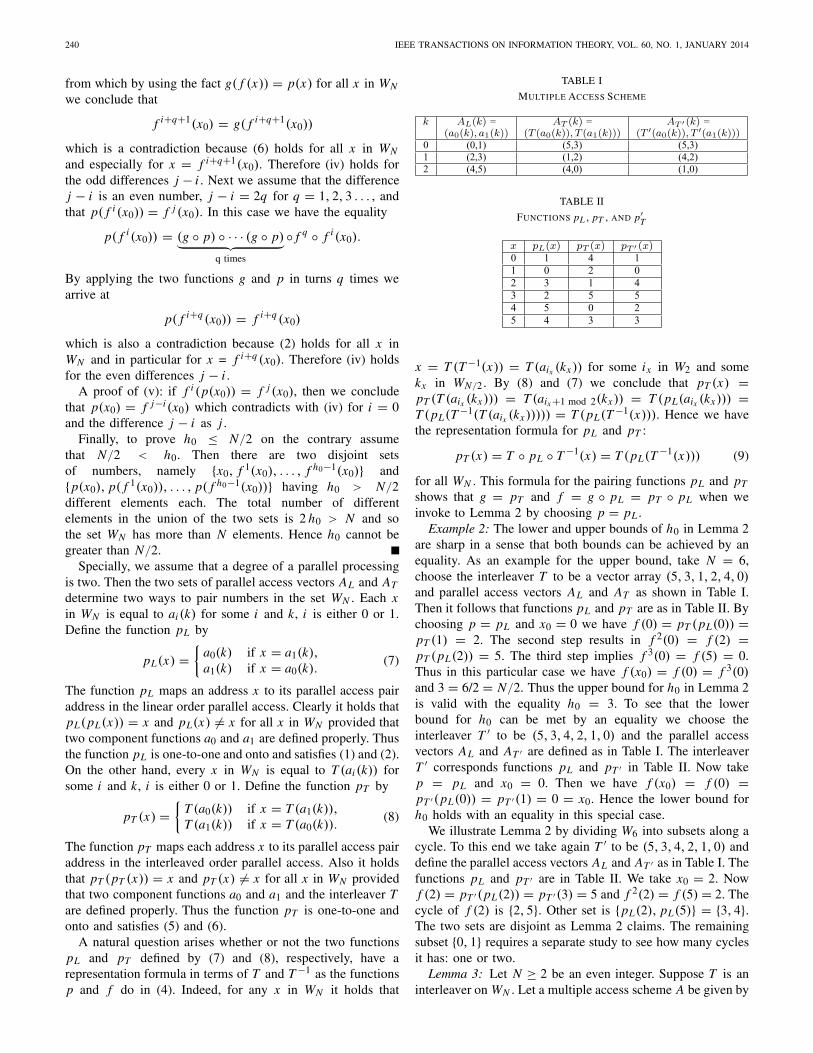
TABLE I
MULTIPLE ACCESS SCHEME
TABLE II
FUNCTIONS pL , pT , AND p′T
x = T (T −1(x)) = T (aix (kx)) for some ix in W2 and somekx in WN/2. By (8) and (7) we conclude that pT (x) =pT (T (aix (kx))) = T (aix +1 mod 2(kx)) = T (pL(aix (kx))) =T (pL(T −1(T (aix (kx))))) = T (pL(T −1(x))). Hence we havethe representation formula for pL and pT :
pT (x) = T ◦ pL ◦ T −1(x) = T (pL(T −1(x))) (9)
for all WN . This formula for the pairing functions pL and pT
shows that g = pT and f = g ◦ pL = pT ◦ pL when weinvoke to Lemma 2 by choosing p = pL .
Example 2: The lower and upper bounds of h0 in Lemma 2are sharp in a sense that both bounds can be achieved by anequality. As an example for the upper bound, take N = 6,choose the interleaver T to be a vector array (5, 3, 1, 2, 4, 0)and parallel access vectors AL and AT as shown in Table I.Then it follows that functions pL and pT are as in Table II. Bychoosing p = pL and x0 = 0 we have f (0) = pT (pL(0)) =pT (1) = 2. The second step results in f 2(0) = f (2) =pT (pL(2)) = 5. The third step implies f 3(0) = f (5) = 0.Thus in this particular case we have f (x0) = f (0) = f 3(0)and 3 = 6/2 = N/2. Thus the upper bound for h0 in Lemma 2is valid with the equality h0 = 3. To see that the lowerbound for h0 can be met by an equality we choose theinterleaver T ′ to be (5, 3, 4, 2, 1, 0) and the parallel accessvectors AL and AT ′ are defined as in Table I. The interleaverT ′ corresponds functions pL and pT ′ in Table II. Now takep = pL and x0 = 0. Then we have f (x0) = f (0) =pT ′(pL(0)) = pT ′(1) = 0 = x0. Hence the lower bound forh0 holds with an equality in this special case.
We illustrate Lemma 2 by dividing W6 into subsets along acycle. To this end we take again T ′ to be (5, 3, 4, 2, 1, 0) anddefine the parallel access vectors AL and AT ′ as in Table I. Thefunctions pL and pT ′ are in Table II. We take x0 = 2. Nowf (2) = pT ′(pL(2)) = pT ′(3) = 5 and f 2(2) = f (5) = 2. Thecycle of f (2) is {2, 5}. Other set is {pL(2), pL(5)} = {3, 4}.The two sets are disjoint as Lemma 2 claims. The remainingsubset {0, 1} requires a separate study to see how many cyclesit has: one or two.
Lemma 3: Let N ≥ 2 be an even integer. Suppose T is aninterleaver on WN . Let a multiple access scheme A be given by
NIEMINEN: CONTENTION-FREE PARALLEL ACCESS 241
AL(k) = (a0(k), a1(k)) and AT (k) = (T (a0(k)), T (a1(k))) forall k in WN/2. Then there exists a partition of WN into twodisjoint equally sized sets U0 and U1 with 2-by-2 butterflynetwork transition matrices Bk and Ck such that
(i) Bk AL(k) ∈ U0 × U1 and(ii) Ck AT (k) ∈ U0 × U1
for all k in WN/2.Proof: We begin with defining S0 = WN . Then we take
a0(0) from S0 and construct two sequences x0;i and y0;i basedon Lemma 2 as follows. The function p of Lemma 2 is chosento be pL defined by (7). Assign x0;0 = a0(0). We invoke toLemma 2 to obtain the sequences x0;i and y0;i by x0;i =f i (x0;0) and y0;i = pL(x0;i) for all i in Wh0 and 1 ≤ h0 ≤N/2. Define S1 to be a set which is obtained by removing allthe numbers x0;i and y0;i from the set S0, that is,
S1 = {w ∈ S0 : w �= x0;i and w �= y0;i for all i ∈ Wh0}.Second sequences x1;i and y1;i are derived in a similar wayas follows. If S1 is not empty, then pick ai1 (k1) from S1.Assign x1;0 = ai1(k1). Again we invoke to Lemma 2 to getnumbers x1;i = f i (x1;0) and y1;i = pL(x1;i) for all i in Wh1
with 1 ≤ h1 ≤ N/2. In general, a next set Sj is deduced byremoving all the numbers x j−1;i and y j−1;i from the set Sj−1:
Sj = {w ∈ Sj−1 : w �= x j−1;i and
w �= y j−1;i for all i ∈ Wh j−1}It follows from Lemma 2 that at each step a number of ele-ments in a next Sj is at least two less than in a previous Sj−1.Thus after a finite number of steps the set Sj will be emptyand then we stop the process to select numbers from Sj . Letus denote the index of a first empty set step by r . It holds that1 ≤ r ≤ N/2 and h0+h1+· · ·+hr−1 = N/2. We denote by U0and U1 the two sets of the numbers x j ;i and y j ;i , respectively.In other words, we have
U0 = {w ∈ WN : w = x j ;i for all j ∈ Wr and i ∈ Wh j }and
U1 = {w ∈ WN : w = y j ;i for all j ∈ Wr and i ∈ Wh j }.Both sets have N/2 elements each. If there is x in WN whichdoes not belong to U0 ∪ U1, then by Lemma 2 there are 2 hx
numbers, namely, x , f (x),…, f hx −1(x), pL(x), pL( f (x)),…,pL( f hx −1(x)), which are not in U0∪U1 either. This contradictswith the fact that Sr is empty by Lemma 2. Therefore x is inU0 ∪ U1 and WN is a subset of U0 ∪ U1. It follows fromthe construction of U0 and U1 that U0 ∪ U1 is a subset ofWN . Hence WN = U0 ∪ U1. On the other hand, if there isx in U0 ∩ U1, then x = pL(x). This is not possible becausethe component functions a0 and a1 cannot be equal at anypoint and the function pL is defined by the formula (7). HenceU0 ∩ U1 is empty. This completes a proof of the partition ofWN into two disjoint equally sized sets.
A proof of (i): let AL(k) be any 2-dimensional vectorin a linear order multiple access scheme, that is, AL(k) =(a0(k), a1(k)) and k is in WN/2. It follows from the firstpart of this proof and that either a0(k) is in U0 or a0(k)is in U1. If a0(k) ∈ U0, then by Lemma 2 we conclude
that a1(k) = pL(a0(k)) ∈ U1. In the case of a0(k) ∈ U1it follows from Lemma 2 that there is a wk in U0 witha0(k) = pL(wk) and hence we arrive at a1(k) = pL(a0(k)) =pL(pL(wk)) = wk ∈ U0. Therefore for any AL(k) =(a0(k), a1(k)), k in WN/2, it holds either (a0(k), a1(k)) ∈U0 × U1 or (a1(k), a0(k)) ∈ U0 × U1. This completes theproof for (i).
A proof of (ii): take any 2-dimensional vectorfrom an interleaved order multiple access schemeAT (k) = (T (a0(k)), T (a1(k))) for k in WN/2. It followsfrom the first part of this proof that either T (a0(k)) ∈ U0 orT (a0(k)) ∈ U1. By (7) and (4) we conclude that T (a1(k)) =T (pL(a0(k))) = T ◦ pL ◦ T −1 ◦ T (a0(k)) = g(T (a0(k))).Moreover, by (3) and (4) we obtain f (x) = g(pL(x)) andf −1(x) = f hx −1(x) = pL(g(x)) for all x in WN . Hence itholds that
T (a1(k)) = f ◦ pL(T (a0(k))) = pL ◦ f hk−1(T (a0(k))).
If T (a0(k)) is in U0, then the whole cycle of T (a0(k)) isin U0 as well. In particular, f hk−1(T (a0(k))) belongs to U0.Therefore T (a1(k)) = pL ◦ f hk−1(T (a0(k))) is in U1. Onthe other hand, if T (a0(k)) is in U1, then it follows fromLemma 2 that there is a wk in U0 with T (a0(k)) = pL(wk).In this case we have T (a1(k)) = f ◦ pL(T (a0(k))) = f (wk)and hence T (a1(k)) is in U0. Therefore we have either(T (a0(k)), T (a1(k))) ∈ U0 × U1 or (T (a1(k)), T (a0(k))) ∈U0 × U1 and (ii) follows.
We illustrate Lemma 3 by constructing a partition of W6into U0 and U1. Again we take T ′ to be (5, 3, 4, 2, 1, 0) anddefine the parallel access vectors AL and AT ′ as in Table I.The functions pL and pT ′ are in Table II. In this case wehave f (0) = pT ′(pL(0)) = 0 and pL(0) = 1. Moreover,f (2) = 5, f 2(2) = 2, pL(2) = 3, and pL(5) = 4. Thereforewe can choose U0 = {0, 2, 5} and U1 = {1, 3, 4}. Three2-by-2 butterfly network transition matrices Bk for the linearorder parallel access vectors AL(k) for k in W3 are:
[
1 00 1
]
0,
[
1 00 1
]
1, and
[
0 11 0
]
2. (10)
Three 2-by-2 butterfly network transition matrices Ck for theinterleaved order parallel access vectors AT ′(k) for k in W3are: [
1 00 1
]
0,
[
0 11 0
]
1, and
[
0 11 0
]
2. (11)
The sets U0 and U1 satisfy the claims of Lemma 3.
B. Case 2m for m = 2, 3, 4, ...
Next we take an inductive step by assuming that Theorem 1holds for m − 1. Then we prove that Theorem 1 holds alsofor m. To this end, a multiple access scheme A′ having 2m−1
components in parallel access vectors is derived from theoriginal multiple access scheme A having 2m components inparallel access vectors. Then we invoke to Theorem 1 with A′and combine by using [2] and Lemma 3 two 2m−1 × 2m−1
butterfly networks to one 2m × 2m butterfly network.Proof: [Proof of Theorem 1] the linear order parallel
access vectors A′L(k) = (c0(k), c1(k), . . . , c2m−1−1(k)) for k
242 IEEE TRANSACTIONS ON INFORMATION THEORY, VOL. 60, NO. 1, JANUARY 2014
in WN/2m−1 are derived from vectors in AL by
c j (k) ={
a j (q) for even k = 2 q;a j+2m−1(q) for odd k = 2 q + 1; (12)
for all j in W2m−1 and for all q in WN/2m . The inter-leaved order parallel access vectors A′
T (k) are given byA′
T (k) = (T (c0(k)), T (c1(k)), T (c2(k)), . . . , T (c2m−1−1(k)))for all k in WN/2m−1 . It follows that two vectors A′
L(2 q)and A′
L(2 q + 1) in A′L correspond one vector AL(q) in AL ,
that is, when we concatenate A′L(2 q) and A′
L(2 q + 1) weget AL(q): AL(q) = (A′
L(2 q), A′L(2 q + 1)) for all q in
WN/2m . The same holds for vectors in AT as well: AT (q) =(A′
T (2 q), A′T (2 q + 1)) for all q in WN/2m . By the inductive
assumption we deduce that there exists a partition of WN into2m−1 disjoint sets U ′
i of N/2m−1 elements with 2m−1 × 2m−1
butterfly network transition matrices B ′k and C ′
k such that(i’) B ′
k A′L(k) ∈ U ′
0 × U ′1 × U ′
2 × · · · × U ′2m−1−1
and(ii’) C ′
k A′T (k) ∈ U ′
0 × U ′1 × U ′
2 × · · · × U ′2m−1−1
for all k in WN/2m−1 .By the induction assumptions (i’) and (ii’) every set U ′
ihas i :th components of vectors B ′
k A′L(k) and C ′
k A′T (k). This
means that elements of the set U ′i can be listed in two
different orders. Define a linear order of elements in U ′i by
ui;k = B ′k A′
L(k)i for each k in WN/2m−1 where B ′k A′
L(k)i
is a i :th component of a vector B ′k A′
L(k). Thus the list ofnumbers ui;0, ui;1, ui;2, . . . , ui;N/2m−1−1 represents the set U ′
iin the linear order. On the other hand, by (ii’) we conclude thati :th components C ′
k A′T (k)i of vectors C ′
k A′T (k) are in U ′
i aswell. Therefore a function Ti to permute the set U ′
i is obtainedfrom the relations ui;mk = C ′
k A′T (k)i by Ti (k) = mk for all k
in WN/2m−1 . It follows from the induction assumption that Ti isa one-to-one and onto function and an interleaver on WN/2m−1 .Thus every U ′
i has its own interleaver Ti . The second listof numbers ui;Ti (0), ui;Ti (1), ui;Ti (2), . . . , ui;Ti (N/2m−1−1) repre-sents the set U ′
i in the interleaved order.We define a two dimensional multiple access scheme Ai
by Ai;L(q) = (2 q, 2 q + 1) and by Ai;Ti (q) = (Ti (2 q),Ti (2 q + 1)) for all q in WN/2m in the linear order and inthe interleaved order, respectively. Now Lemma 3 implies thatthere exists a partition of WN/2m−1 into two disjoint sets Ui;0and Ui;1 of N/2m elements with 2-by-2 butterfly networktransition matrices Bi;q and Ci;q such that(i) Bi;q Ai;L(q) ∈ Ui;0 × Ui;1 and
(ii) Ci;q Ai;Ti (q) ∈ Ui;0 × Ui;1for all q in WN/2m .
The set U ′i is split into two sets denoted by Ui and U2m−1+i
as follows
Ui = {x ∈ U ′i : x = ui;k and k ∈ Ui;0} (13)
U2m−1+i = {x ∈ U ′i : x = ui;k and k ∈ Ui;1} (14)
for all i in W2m−1 . By Lemma 3 we conclude that the sets Ui
and U2m−1+i are disjoint, they have N/2m elements each, andU ′
i = Ui ∪ U2m−1+i . Hence we have proved the partition ofWN into 2m disjoint equally sized sets Ui for all i in W2m ofTheorem 1.
To prove the claim (i) of Theorem 1 we combine twoconsecutive 2m−1 ×2m−1 butterfly network transition matrices
B ′2 q and B ′
2 q+1 with 2×2 butterfly network matrices Bi;q , i inW2m−1 , to get one 2m × 2m butterfly network transition matrixBq for all q in WN/2m . This kind of construction is possiblebecause butterfly networks have a hierarchical structure suchthat a 2m × 2m butterfly network can be constructed fromtwo 2m−1 × 2m−1 butterfly networks and 2 × 2 butterfly net-works [2]. The number of the needed 2 ×2 butterfly networksis 2m−1. To this end we construct an auxiliary 2m ×2m squarematrix Eq from 2×2 butterfly network matrices Bi;q with i inW2m−1 . Four elements Eq(i, i), Eq(i, 2m−1+i), Eq(2m−1+i, i)and Eq(2m−1 + i, 2m−1 + i) are taken from the matrix Bi;q bythe formula
[
Eq(i, i) Eq(i, 2m−1 + i)Eq(2m−1 + i, i) Eq(2m−1 + i, 2m−1 + i)
]
= Bi;q (15)
for all i in W2m−1 . All other elements of Eq are equal to zero.Based on the inductive assumption (i’) we define 2m × 2m
butterfly transition matrices Bq by
Bq = Eq
[
B ′2q 0
0 B ′2q+1
]
for all q in WN/2m . Next we show that r :th componentsBq AL(q)r of vectors Bq AL(q) belong to Ur for all r in W2m .First of all, we have
Bq AL(q) = Bq
[
A′L(2q)
A′L(2q + 1)
]
= Eq
[
B ′2q 0
0 B ′2q+1
] [
A′L(2q)
A′L(2q + 1)
]
= Eq
[
B ′2q A′
L(2q)
B ′2q+1 A′
L(2q + 1)
]
= Eq
⎡
⎢
⎢
⎢
⎢
⎢
⎢
⎢
⎢
⎣
u0;2q...u2m−1−1;2qu0;2q+1...u2m−1−1;2q+1
⎤
⎥
⎥
⎥
⎥
⎥
⎥
⎥
⎥
⎦
.
It follows immediately from the choice (15) that Eq permutesui;2q and ui;2q+1 in the same way as Bi;q permutes vectorsAi;L(q) = (2 q, 2 q + 1). Therefore for all x ∈ Ui and y ∈U2m−1+i we have x = Bi;q(0, 0)ui;2q + Bi;q(0, 1)ui;2q+1 andy = Bi;q(1, 0)ui;2q + Bi;q (1, 1)ui;2q+1 for each i in W2m−1 ,respectively. Thus for r = 0, 1, . . . , 2m−1 − 1 it holds that
and so Bq AL(q)r is in Ur . On the other hand, for r =2m−1, 2m−1 + 1, . . . , 2m − 1 we have
Bq AL(q)r = Eq(r, r − 2m−1)ur−2m−1;2q
+Eq(r, r)ur−2m−1;2q+1
= Br−2m−1;q(1, 0)ur−2m−1;2q
+Br−2m−1;q(1, 1)ur−2m−1;2q+1,
which belongs to Ur . This completes the proof of (i) ofTheorem 1.
NIEMINEN: CONTENTION-FREE PARALLEL ACCESS 243
A proof of the claim (ii) of Theorem 1 is similar to thatof (i). In this case we construct an auxiliary 2m × 2m squarematrix ET ;q from 2×2 butterfly network matrices Ci;q with iin W2m−1 . Each set U ′
i is represented in the interleaved orderTi as ui;Ti (0), ui;Ti (1), . . . , ui;Ti (N/2m−1−1) for each i in W2m−1 .Four elements ET ;q(i, i), ET ;q(i, 2m−1 + i), ET ;q(2m−1 + i, i)and ET ;q(2m−1 + i, 2m−1 + i) are assigned to be equal toelements of the matrix Ci;q by the formula[
ET ;q(i, i) ET ;q(i, 2m−1 + i)ET ;q(2m−1 + i, i) ET ;q(2m−1 + i, 2m−1 + i)
]
= Ci;q (16)
for each i in W2m−1 . Then by the inductive assumption (ii’)we define 2m × 2m butterfly transition matrices Cq by
Cq = ET ;q[
C ′2q 0
0 C ′2q+1
]
for all q in WN/2m . Likewise in the proof of Theorem 1(i) weconclude that
Cq AT (q) = Cq
[
A′T (2q)
A′T (2q + 1)
]
= ET ;q[
C ′2q 0
0 C ′2q+1
] [
A′T (2q)
A′T (2q + 1)
]
= ET ;q[
C ′2q A′
T (2q)
C ′2q+1 A′
T (2q + 1)
]
= ET ;q
⎡
⎢
⎢
⎢
⎢
⎢
⎢
⎢
⎢
⎣
u0;Ti (2q)...u2m−1−1;Ti (2q)
u0;Ti (2q+1)...u2m−1−1;Ti (2q+1)
⎤
⎥
⎥
⎥
⎥
⎥
⎥
⎥
⎥
⎦
.
Now, if r = 0, 1, . . . , 2m−1 − 1, it follows that
Cq AT (q)r = ET ;q(r, r)ur;Tr (2q) +ET ;q(r, 2m−1 + r)ur;Tr (2q+1)
= Cr;q (0, 0)ur;Tr (2q) + Cr;q (0, 1)ur;Tr (2q+1)
and hence by invoking to (16) we see that Cq AL(q)r is in Ur
for all q in WN/2m . Finally, if r = 2m−1, 2m−1 +1, . . . , 2m −1,we have
Cq AT (q)r = ET ;q(r, r − 2m−1)ur−2m−1;Tr−2m−1 (2q)
+ET ;q(r; r)ur−2m−1;Tr−2m−1 (2q+1)
= Cr−2m−1;q(1, 0)ur−2m−1;Tr−2m−1 (2q)
+ Cr−2m−1;q(1, 1)ur−2m−1;Tr−2m−1 (2q+1)
from which and from (16) we conclude that Cq AL(q)r is in Ur
for all q in WN/2m as well. Thus the claim (ii) of Theorem 1follows.
The partition of WN into the sets Ui is recursively dyadicas follows. In the proof of the partition we concluded thatU ′
i = Ui ∪ U2m−1+i . Hence sets Ui and U2m−1+i are leaves ofa binary tree which stems from the set WN recursively. Thesize of the tree depends on m.
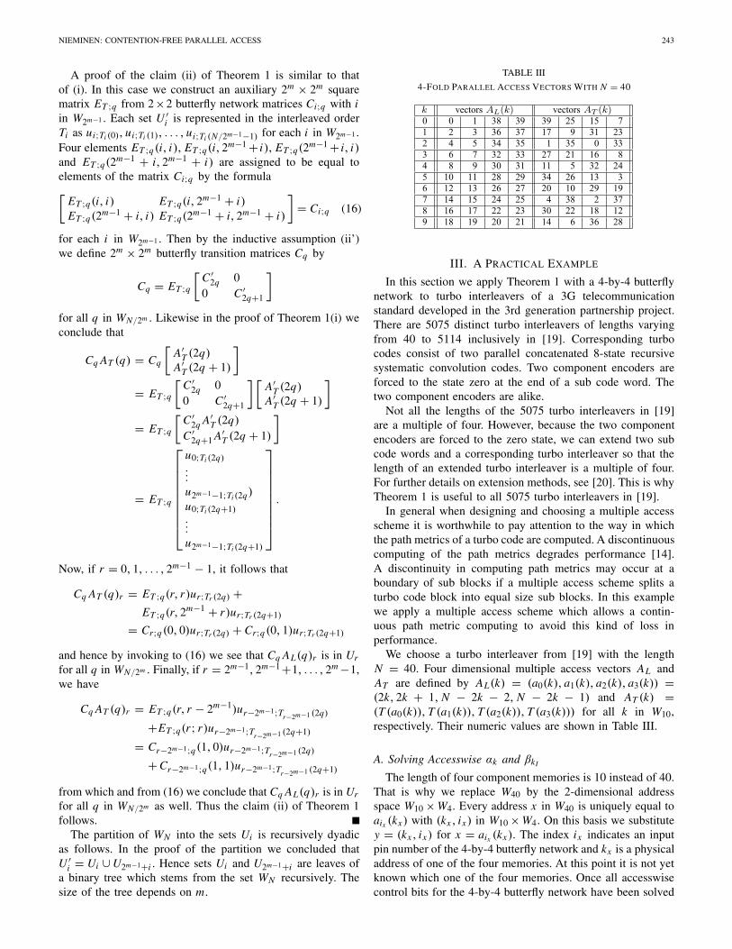
TABLE III
4-FOLD PARALLEL ACCESS VECTORS WITH N = 40
III. A PRACTICAL EXAMPLE
In this section we apply Theorem 1 with a 4-by-4 butterflynetwork to turbo interleavers of a 3G telecommunicationstandard developed in the 3rd generation partnership project.There are 5075 distinct turbo interleavers of lengths varyingfrom 40 to 5114 inclusively in [19]. Corresponding turbocodes consist of two parallel concatenated 8-state recursivesystematic convolution codes. Two component encoders areforced to the state zero at the end of a sub code word. Thetwo component encoders are alike.
Not all the lengths of the 5075 turbo interleavers in [19]are a multiple of four. However, because the two componentencoders are forced to the zero state, we can extend two subcode words and a corresponding turbo interleaver so that thelength of an extended turbo interleaver is a multiple of four.For further details on extension methods, see [20]. This is whyTheorem 1 is useful to all 5075 turbo interleavers in [19].
In general when designing and choosing a multiple accessscheme it is worthwhile to pay attention to the way in whichthe path metrics of a turbo code are computed. A discontinuouscomputing of the path metrics degrades performance [14].A discontinuity in computing path metrics may occur at aboundary of sub blocks if a multiple access scheme splits aturbo code block into equal size sub blocks. In this examplewe apply a multiple access scheme which allows a contin-uous path metric computing to avoid this kind of loss inperformance.
We choose a turbo interleaver from [19] with the lengthN = 40. Four dimensional multiple access vectors AL andAT are defined by AL(k) = (a0(k), a1(k), a2(k), a3(k)) =(2k, 2k + 1, N − 2k − 2, N − 2k − 1) and AT (k) =(T (a0(k)), T (a1(k)), T (a2(k)), T (a3(k))) for all k in W10,respectively. Their numeric values are shown in Table III.
A. Solving Accesswise αk and βkI
The length of four component memories is 10 instead of 40.That is why we replace W40 by the 2-dimensional addressspace W10 × W4. Every address x in W40 is uniquely equal toaix (kx) with (kx , ix) in W10 × W4. On this basis we substitutey = (kx , ix) for x = aix (kx). The index ix indicates an inputpin number of the 4-by-4 butterfly network and kx is a physicaladdress of one of the four memories. At this point it is not yetknown which one of the four memories. Once all accesswisecontrol bits for the 4-by-4 butterfly network have been solved
244 IEEE TRANSACTIONS ON INFORMATION THEORY, VOL. 60, NO. 1, JANUARY 2014
TABLE IV
R , R−1 , AND AR FOR N = 40
the rightmost term ix in (kx , ix) can be ignored. The originalturbo interleaver T with N = 40 cannot be applied to W10×W4.So we replace it by new one as follows. We define the physicalturbo interleaver R of T from W10 × W4 to itself by
R(k1, i1) = (k2, i2) if and only if T (ai1(k1)) = ai2(k2) (17)
for all (k1, i1) and (k2, i2) in W10 × W4. The de-interleaverof R is called R−1. Table IV shows the numeric values of Rand R−1. We denote a multiple access scheme related to the2-dimensional address space W10 × W4 by the same notationA as the original one. The 2-dimensional address format andR as an interleaver prevent us from confusing the two multipleaccess schemes. The linear order parallel access vectors in thephysical format are
AL(k) = ((k, 0), (k, 1), (k, 2), (k, 3)) (18)
for all k in W10. The interleaved order parallel access vectorfunction AR is equal to the physical turbo interleaver R rowby row, i.e.
AR(k) = (R(k, 0), R(k, 1), R(k, 2), R(k, 3)) (19)
for all k in W10. Their numeric values are shown in Table IV.For example, from Table III, Table IV, and (17) we concludethat T (a0(0)) = T (0) = 39 = 40 − 2 · 0 − 1 = a3(0),(k1, i1) = (0, 0), (k2, i2) = (0, 3), and R(0, 0) = (0, 3).In particular, R(0, 0) �= 39 = T (0).
The physical linear order parallel access vectors AL(k) andthe physical interleaved order parallel access vectors AR(k), kin W10, are valid at the left side of the 4-by-4 butterfly networkin Fig. 1(b). Nevertheless, we can use neither any of addressvectors AL(k) nor AR(k) to access the four memories thruthe 4-by-4 butterfly network because accesswise control bitsare still unknown. In practice these modifications are easyto do in the design phase of a hardware because the desiredmultiple access scheme is known explicitly. The physical turbointerleaver R requires the same amount of a memory as theoriginal turbo interleaver T . The use of the physical parallelaccess vectors AL and AR is independent of the use of theoriginal parallel access vectors AL and AT . However, theyshare accesswise control bits of the 4-by-4 butterfly network.The independent use of the two parallel access vector typesstems from the fact that the address substitution described
above is unique and butterfly networks are alike in both ofthe cases.
We denote accesswise control bits of the 4-by-4 butterflynetwork for the physical linear order parallel access vectorsAL(k) by αk; j for all (k, j) in W10 × W4. These four bitsαk; j are mapped to z j by αk; j = z j with z j is as in Fig. 1(b)for all j in W4. A corresponding 4-bit number is denotedby αk such that αk;0 is the least significant bit of that number.In the similar fashion, accesswise control bits of the 4-by-4butterfly network for the physical interleaved order parallelaccess vectors AR(k) are denoted by βk; j for all (k, j) inW10 × W4. Each βk; j is equal to z j of Fig. 1(b) for all j inW4. Furthermore, βk stands for a 4-bit number of bits βk; jin which βk;0 is the least significant bit. It is pointed outthat j in W4 is not an input pin index for the 4-by-4 butterflynetwork but an index for control bits of the the 4-by-4 butterflynetwork. In this special case the two indexes have the samerange.
The control bits αk and βk are solved based on theproof of Theorem 1. We begin with solving control bits to2-by-2 butterfly networks and then we joint two 2-by-2 but-terfly networks to one 4-by-4 butterfly network. We applyLemma 2 and Lemma 3 to W10 × W4 with R and the physicalparallel access vectors AL and AR to derive the partition ofW10 × W4 into two sets U0 and U1. Although Lemma 2 andLemma 3 are formulated to the one dimensional set WN theyare applicable to the physical address space W10 ×W4 as well.The two sets U0 and U1 are again to divided to two sets eachaccording to (13) and (14). This means that we have three twodimensional parallel access problems to solve. Hence we needthree different functions f in Lemma 3 for constructing thefinal partition of W10 ×W4 to four sets. The first function f isused to get the two sets U0 and U1. The second function f0 andthe third function f1 are used to split U0 and U1, respectively.The first f is responsible for solving accessible control bitsfor the two 2-by-2 butterfly networks in the leftmost columnin Fig. 1(b). When the sum of corresponding cycle lengths h j
is equal to N/2 we know that we have solved all accesswisecontrol bits of the leftmost column. The functions f0 and f1are responsible for solving accesswise control bits for the2-by-2 butterfly network of z2 and z3, respectively, in therightmost column in Fig. 1(b). The number of elements inU0 is N/2. Therefore all the f0-specific control bits havebeen solved when the sum of the cycle lengths h j0 of f0is N/4. The same holds for f1 as well. We use three differentfunctions p, p0, and p1 of Lemma 2 to construct requiredf , f0, and f1, respectively. The function p maps two inletsof the 2-by-2 butterfly networks of z0 and z1 in Fig. 1(b)from one to the other. The function p0 is associated with the2-by-2 butterfly network of z2 in Fig. 1(b). The two uniquepaths from input pins of the 4-by-4 butterfly network lead tothe two inlets of the 2-by-2 butterfly network. The function p0maps the two input pins from one to the other via the 2-by-2butterfly network of z2. The function p1 is the same mappingfor the 2-by-2 butterfly network of z3. The functions p0 andp1 apply accesswise control bits in the leftmost column of the4-by-4 butterfly network to map two input pins from one to theother.
NIEMINEN: CONTENTION-FREE PARALLEL ACCESS 245
In general, this process can be repeated until the size of afinal 2m × 2m butterfly network is achieved. To divide a setinto two subsets by (13) and (14) is equivalent to solve theaccesswise control bits of a 2-by-2 sub butterfly network in the2m × 2m butterfly network. All the 2m−1 2-by-2 sub butterflynetworks associated with (13) and (14) belong to the samecolumn of the 2m ×2m butterfly network. When moving from acolumn to the next column the number of required fb doublesand the sum of cycle lengths of each fb goes halves. The firstcolumn has one f and the last column 2m−1 different fbs.The total number of f s is 1 + 2 + · · · + 2m−1 = 2m − 1for the 2m × 2m butterfly network. Every fb corresponds toa two dimensional parallel access problem. This means thatwe obtain accesswise control bits αk and βk for the 2m × 2m
butterfly network by solving 2m − 1 two dimensional parallelaccess problems one by one. The sum of cycle lengths h jb ofone fb in the last column is equal to N/2m . The total sumof all cycle lengths in one column of the 2m × 2m butterflynetwork is always equal to N/2.
The control bits z j , j in Wm2m−1 , of the 2m × 2m butterflynetwork are associated with the columnwise functions fb asfollows. Let r in Wm be a column index. The control bit z j
is set by the function fb of the column r if j ≡ b (mod 2r )for j = r2m−1, r2m−1 + 1, . . . , (r + 1)2m−1 − 1 and for bin W2r . One control bit z j corresponds to one 2-by-2 subbutterfly network. It is pointed out that the index b has mdistinct columnwise ranges from 0 to 2r − 1 for r in Wm .This dependency of b on the columns of the 2m ×2m butterflynetwork is not shown explicitly to simplify the notation. Everyfb has a function pb which is associated with the 2-by-2 subbutterfly networks of fb in the 2m ×2m butterfly network. Thenumber of 2-by-2 sub networks of fb per column is 2m−1−r
for r in Wm . Two unique paths from input pins of the 2m ×2m
butterfly network lead to two inlets of a 2-by-2 sub butterflynetwork of fb . The function pb maps the two input pins fromone to the other. The function pb uses the solved control bits incolumns which are between the two input pins of the 2m ×2m
butterfly network and the 2-by-2 sub butterfly network of pb
to map two input pins from one to the other. The function fb,b ∈ W2r , to solve two dimensional access problems in the r :thcolumn of the 2m × 2m butterfly network is defined by
fb(k, i) = R ◦ pb ◦ R−1 ◦ pb(k, i) (20)
for all (k, i) in WN/2m × W2m for r in Wm . Formally fb isdefined only on that subset of WN/2m × W2m which fb splitsinto two sets.
In the proof of Theorem 1 each set U ′i is represented in
the linear order and in the interleaved order. The interleaveron U ′
i is actually the restriction of the composite functionof the original interleaver T and component functions a j tothe set U ′
i . This justifies the use of R in (20) for all fb.As discussed earlier, Theorem 1, Lemma 2, and Lemma 3are applicable to WN/2m × W2m in addition to WN .
Solving bits in the r :th column deals with the r :th bits ofthe input pin indexes i = im−1 . . . ir . . . i0 in W2m in the binarynumber notation. This is based on the fact that m control bitsfor a path thru any 2m × 2m butterfly network connecting aninlet to an outlet are equal to the bitwise exclusive or-operation
of the indexes of the inlet and the outlet as binary numbers [2].We have freedom to choose how to set control bits to 2-by-2sub butterfly networks which belong to the same cycle of fb.The internal routing connections between 2-by-2 sub networksin the 2m × 2m butterfly network determines how to calculatethe bit indexes j and jI of control bits αk; j and βkI ; jI forgiven input pins i and i I , respectively. As we apply the samebutterfly network structure to the two parallel access orders theformula is the same for the two control bits. The bit index jfor αk; j is calculated by
j = r2m−1 + 2r (i ÷ 2r+1) + b (21)
for all r in Wm , b in W2r , and i in W2m . Here x ÷ y is aquotient of x and y. We assign the linear order control bitαk; j to be equal to ir where ir is the r :th bit of i ∈ W2m ,an input pin index to the 2m × 2m butterfly network. Theassignment αk; j = ir means that the input pin i is connectedto the upper outlet of the 2-by-2 sub butterfly network of j .We map i by (k, i p) = pb(k, i) to the other input pin i p ofthe 2m × 2m butterfly network which is also connected to the2-by-2 sub butterfly network of j . Specially, (k, i) and (k, i p)belong to the k:th linear order parallel access vector AL(k).The assignment αk; j = ir implies also that the input pin i p isconnected to the lower outlet of the same 2-by-2 sub butterflynetwork of j .
It follows from the composite structure of fb that we set theinterleaved order control bit βkI ; jI to be equal to the r :th bitof the other input pin index of the 2m × 2m butterfly networkbeing connected to the 2-by-2 sub butterfly network of jI inWm2m−1 . In other words, βkI ; jI = i I ;r where the bit index jI =r2m−1 + 2r (i I ÷ 2r+1) + b and (kI , i I ) = pb(R−1(pb(k, i)))for all r in Wm , b in W2r , and i in W2m . The other inputpin index means here applying pb to R−1(pb(k, i)). As inthe case of αk; j the assignment βkI ; jI = i I ;r implies thatthe input pin i I is connected to the upper outlet of the2-by-2 sub butterfly network corresponding to jI . Denote(kI , i I p) = R−1(pb(k, i)). The two addresses (kI , i I ) and(kI , i I p) are in the kI :th interleaved order parallel access vectorAR(kI ). Furthermore the assignment βkI ; jI = i I ;r means thatthe input pin i I p is connected to the lower outlet of the same2-by-2 sub butterfly network of jI . The next (k, i) is setequal to R(kI , i I ). We repeat these steps until a cycleends. Because for the next (k, i) it holds that (k, i) =R(R−1(k, i)) = R(kI , i I ) these choices to set control bitsαk; j and βkI ; jI make sure that a data value ends up to thesame output pin of the the 2m × 2m butterfly network inthe two parallel access orders. Furthermore, it follows from(kI , i I p) = R−1(k, i p)) that the bits αk; j and βkI ; jI connectsthe input pin i p in AL(k) and the input pin i I p in AR(kI )to the same output pin in the two parallel access orders asexpected by Theorem 1.
Cycles are disjoint. That is why we search for free cyclesof fb access by access based on solved control bits αk in ther :th column. Once we have found an unsolved bit αk; js forsome js = r2m−1, r2m−1 + 1, . . . , (r + 1)2m−1 − 1 we mapthe control bit index js to an input pin index is of the 2m ×2m
butterfly network. Due to the structure of the 2m ×2m butterflynetwork there are two unique input pins which are connected
246 IEEE TRANSACTIONS ON INFORMATION THEORY, VOL. 60, NO. 1, JANUARY 2014
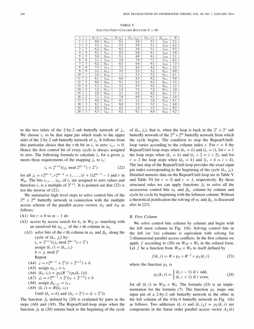
TABLE V
SOLVING FIRST COLUMN BITS FOR N = 40
to the two inlets of the 2-by-2 sub butterfly network of js .We choose is to be that input pin which leads to the upperinlet of the 2-by-2 sub butterfly network of js . It follows fromthis particular choice that the r :th bit in is is zero: is;r = 0.Hence the first control bit of every cycle is always assignedto zero. The following formula to calculate is for a given jsmeets these requirements of the mapping js to is :
is = 2r+1(( js mod 2m−1) ÷ 2r ) (22)
for all js = r2m−1, r2m−1 + 1, . . . , (r + 1)2m−1 − 1 and r inWm . The bits ir;s . . . i0;s of is are assigned to zero values andtherefore is is a multiple of 2r+1. It is pointed out that (22) isnot the inverse of (21).
We summarize high level steps to solve control bits of the2m × 2m butterfly network in connection with the multipleaccess scheme of the parallel access vectors AL and AR asfollows:
(A1) for r = 0 to m − 1 do
(A2) access by access search for ks in WN/2m matching withan unsolved bit αks ; js of the r :th column in αks
(A3) solve bits of the r :th column in αk and βkI along thecycle of (ks, js) by:is = 2r+1(( js mod 2m−1) ÷ 2r )assign (k, i) = (ks, is)b = js mod 2r
Repeat
(A4) j = r2m−1 + 2r (i ÷ 2r+1) + b(A5) assign αk; j = ir
(A6) (kI , i I ) = pb(R−1(pb(k, i)))(A7) jI = r2m−1 + 2r (i I ÷ 2r+1) + b(A8) assign βkI ; jI = i I ;r(A9) (k, i) = R(kI , i I )
Until (ks = k) and ((is ÷ 2r ) = (i ÷ 2r ))
The function fb defined by (20) is evaluated by parts in thesteps (A6) and (A9). The Repeat/Until-loop stops when thefunction fb in (20) returns back to the beginning of the cycle
of (ks, js), that is, when the loop is back in the 2r × 2r subbutterfly network of the 2m ×2m butterfly network from whichthe cycle begins. The condition to stop the Repeat/Untill-loop varies according to the column index r . For r = 0 theRepeat/Until-loop stops when (ks = k) and (is = i), for r = 1the loop stops when (ks = k) and (is ÷ 2 = i ÷ 2), and forr = 2 the loop stops when (ks = k) and (is ÷ 4 = i ÷ 4).The last step of the Repeat/Until-loop provides the exact inputpin index corresponding to the beginning of the cycle (ks, js).Detailed numeric data on the Repeat/Until-loop are in Table Vand Table VI for r = 0 and r = 1, respectively. By thesestructural rules we can apply functions fb to solve all theaccesswise control bits αk and βkI column by column andcycle by cycle by beginning with the leftmost column. Withouta theoretical justification the solving of αk and βkI is discussedalso in [21].
B. First Column
We solve control bits column by column and begin withthe left most column in Fig. 1(b). Solving control bits inthe left (or 1st) columns is equivalent with solving for2-dimensional parallel access conflicts. In the first column weapply f according to (20) on W10 × W4 in the refined form.Let f be a function from W10 × W4 to itself defined by
f (k, i) = R ◦ pL ◦ R−1 ◦ pL(k, i) (23)
where the function pL is
pL(k, i) ={
(k, i − 1) if i odd,(k, i + 1) if i even,
(24)
for all (k, i) in W10 × W4. The formula (24) is an imple-mentation for the formula (7). The function pL maps oneinput pin of a 2-by-2 sub butterfly network to the other inthe left column of the 4-by-4 butterfly network in Fig. 1(b)as follows. Two addresses (k, i) and (k, i p) = pL(k, i) arecomponents in the linear order parallel access vector AL(k)
NIEMINEN: CONTENTION-FREE PARALLEL ACCESS 247
and connected to the two input pins of the 2-by-2 sub butterflynetwork of j = i/2 in the left column of the 4-by-4 butterflynetwork. Similarly two addresses (kI , i I p) = R−1(k, i p) and(kI , i I ) = pL(kI , i I p) are components in the interleaved orderparallel access vector AR(kI ). These two addresses are con-nected to the two input pins of the 2-by-2 sub butterfly networkof jI = i I /2 in the left column of the 4-by-4 butterfly network.The parallel access vectors AL and AR are not modifiedexplicitly. The columns (k, i), (k, i p), (kI , i I p), and (kI , i I )of Table V show numeric values for the four addresses.
The t-column of Table V shows the counter t whichcalculates how many times the function f is evaluated forsolving the two least significant control bits associated with theaccess vectors AL(k) and AR(kI ). By Lemma 2 a maximumvalue of the counter t is 20 which coincides with Table V. Thecounter v of Table V shows how many cycles and what kind ofcycles the function f has in this particular case. The counter vstarts five times from 1. It means that the function f has fivecycles of lengths 9, 5, and 2 of which the length 2 occursthree times. In particular, we have 9 + 5 + 2 + 2 + 2 = 20,as expected by the proof of Lemma 3. The αk; j -column ofTable V shows all the solved bits αk;0 and αk;1 in the firstcolumn of the 4-by-4 butterfly network for the linear orderparallel access vectors AL(k). The βkI ; jI -column of Table Vshows all the solved bits βkI ;0 and βkI ;1 in the first column ofthe 4-by-4 butterfly network for the interleaved order parallelaccess vectors AR(kI ).
The cycles of f are disjoint. That is why we can choosefreely from the two alternatives 0 or 1 how to set a controlbit at a beginning of each cycle. In this example we starteach cycle by the bit zero. The function f determines howthe other control bits along a cycle are set by the leastsignificant bit of an input pin. The (k, i)-column of Table Vshows the points at which the function f is evaluated. Thefunction f is evaluated in four steps row wise as follows. The(k, i p)-column has the address values pL(k, i) when weapply pL to the (k, i)-column row wise. The (kI , i I p)-columnshows the address values of R−1 at the column (k, i p) rowby row. The (kI , i I )-column has the address values of pL atthe (kI , i I p)-column row wise. Finally, the R-column showsthe address values when we apply R to the (kI , i I )-columnrow by row.
For example, take t = 8, at that row (k, i) = (7,3), whichis in the 7:th linear order access vector AL(7) on the inputpin 3 = 1110 of the 4-by-4 butterfly network. The controlbit z1 in Fig. 1(b) is associated with the input pin 3. By (A4)we have j = 1 and by (A5) we assign α7;1 = 10 = i0.This assignment connects the input pin 3 to the upper outletof the 2-by-2 sub butterfly network of z1 in Fig. 1(b). Nextwe evaluate (A6) as pL(R−1(pL(k, i))). The function pL isapplied to (7,3) to get (7,2) in AL(7). Then we evaluate thephysical de-interleaver R−1(7, 2) by Table IV to obtain theindex (4,3) in AR(4). Again we invoke to pL : pL(4, 3) = (4,2)which completes the step (A6). The index (kI , i I ) = (4, 2)belongs to the 4:th interleaved order access vector AR(4) onthe input pin 2 = 1100. Hence i I = 2 in (A6) and (A7). Bythe step (A7) we obtain jI = 1 and the sub indexes for β are4 and 1. That is why we set β4;1 = i I ;0 = 00 by (A8). This
assignment for β4;1 connects the input pin i I = 2 to the upperoutlet of the 2-by-2 sub butterfly network of z1 in Fig. 1(b).By (19) we conclude that AR(4, 2) = R(4, 2). Hence as thefinal step on the row t = 8 we use the physical interleaverR(4, 2) from Table IV to get the index (3,2) in AL(3) whichis the input index (k, i) for the row t = 9.
The row t = 8 of Table V shows the address (7,3) in AL(7)is connected to the upper outlet of the 2-by-2 sub butterflynetwork of α7;1 = 1. Therefore the address (7,2) is connectedto the lower outlet of the same 2-by-2 sub butterfly networkfor the 7:th linear order parallel access vector AL(7). Becauseby Table IV we have R(4, 3) = (7, 2) and R−1(7, 2) = (4, 3),the address (7,2) is connected to the lower outlet of the 2-by-2sub butterfly network of β4;1 = 0 along the input pin 3 forthe 4:th interleaved order parallel access vector AR(4). Hencethe address (7,2) is connected to the lower outlet of the two2-by-2 sub butterfly networks in the two parallel access ordersas expected by Lemma 3.
The solving of the bits along a cycle of the function f iscompleted when the function f returns back to the start index(k, i) = (ks, is) of the cycle for r = 0. The counter v ofTable V has the value 1 five times at each start index: (0,0),(1,0), (3,0), (4,0), and (4,2) at rows 1, 10, 15, 17, and 19,respectively. On the other hand, the R-column of Table V hasthe five values (0,0), (1,0), (3,0), (4,0), and (4,2) at rows 9,14, 16, 18, and 20, respectively, which indicate the ends ofthe corresponding cycles.
The (k, i)-column and (k, i p)-column of Table V showtwo components of AL(k) which the function pL groupstogether for the linear order parallel access. In the sameway the (kI , i I p)-column and (kI , i I )-column indicate twocomponents of AR(kI ) which the function pL joints togetherfor the interleaved order parallel access. For example, at therow t = 4 of Table V the components AL(9, 3) = (9, 3)and AL(9, 2) = (9, 2) belong to AL(9) and the compo-nents AR(6, 0) and AR(6, 1) belong to AR(6). By (19) fromTable IV we see that AR(6, 0) = (9, 2) and AR(6, 1) = (5, 0).The bit α9;1 = 1 connects (9,2) and (9,3) to the loweroutlet and the upper outlet of the 2-by-2 butterfly networkof z1 in Fig. 1(b), respectively. The bit β6;0 = 1 connectsAR(6, 0) = (9, 2) and AR(6, 1) = (5, 0) to the lower outletand the upper outlet the 2-by-2 butterfly network of z0,respectively. This means that the address (9,2) is mapped tothe lower outlet by the two parallel access orders.
C. Second Column
Next we demonstrate how to solve the accesswise controlbits of the two parallel access vectors AL(k) and AR(kI )corresponding to the rightmost column of the 4-by-4 butterflynetwork in Fig. 1(b). In other words, we illustrate the solvingof two most significant bits of αk and βkI for all k and kI
in W10, respectively. As discussed earlier, in this case we usetwo functions f0 and f1 from W10 × W4 to itself to solvethe control bits. The function f0 is responsible for solving theaccesswise control bits of the 2-by-2 butterfly network of z2in Fig. 1(b), i.e. αk;2 and βkI ;2 for all k and kI in W10. Thefunction f1 is related to solving the accesswise control bitsof the 2-by-2 butterfly network of z3 in Fig. 1(b), i.e. αk;3
248 IEEE TRANSACTIONS ON INFORMATION THEORY, VOL. 60, NO. 1, JANUARY 2014
TABLE VI
SOLVING SECOND COLUMN BITS FOR N = 40
and βkI ;3 for all k and kI in W10. The function pb applieseither αk;0 and αk;1 or βkI ;0 and βkI ;1 to determine a pairinput pin for a given input pin in the first column as follows.The two input pins are connected to two different 2-by-2 subbutterfly networks in the first column of the 4-by-4 butterflynetwork and there to the same 2-by-2 sub butterfly networkin the second column of the 4-by-4 butterfly network. Thebits αk;0, αk;1, βkI ;0, and βkI ;1 are the solved control bits inthe first column. We indicate this dependency of pb on thesolved control bits of the first column by pγ ;b for γ = α andγ = β. The basic duty of pγ ;b is to select those two addressesfrom the parallel access vectors AL with γ = α and AR withγ = β which are in Ub by Lemma 3 and are connected totwo different 2-by-2 sub butterfly networks in the first columnand to the two inlets of the 2-by-2 sub butterfly network inthe second column of the 4-by-4 butterfly network. Again thevectors AL and AR are not modified explicitly.
We refine the functions fb and pb of (20) as follows. Forγ = α and γ = β we define the function pγ ;b by
pγ ;b(k, i) ={
(k, 2 + (b⊕
γk;1)) if i1 = 0,(k, (b
⊕
γk;0)) if i1 = 1.(25)
for (k, i) in W10×W4, b = 0 or 1, where⊕
stands for mod 2,and i = i1i0 is the binary number notation for i . The functionpγ ;b plays the role of the function p in Lemma 2 to constructtwo functions f0 and f1. An implementation of pγ ;b is simplebecause it operates on a few bits. For b = 0 and 1 we define fb
by
fb(k, i) = R ◦ pβ;b ◦ R−1 ◦ pα;b(k, i) (26)
for all (k, i) in W10×W4. In particular, the physical interleaverR and de-interleaver R−1 are not changed. The two functionsf0 and f1 deploy the control bits αk;0, αk;1, βkI ;0, and βkI ;1 ofthe leftmost column by the function pγ ;b via pα;b and pβ;b forb = 0 and b = 1, respectively. The notation pα;b shows thatpb gets solved bits from the linear order bit vector αk . In thesimilar way, the notation pβ;b indicates that pb is evaluated
with solved bits from the interleaved order bit vector βkI .Hence the function pb is the same in both of these cases.
In this case two addresses (k, i) and (k, i p) = pα;b(k, i)are components in AL(k). They are connected to the twoinput pins i and i p of the 4-by-4 butterfly network and thereto the two inlets of the 2-by-2 sub butterfly network of jby (A4). Similarly two addresses (kI , i I p) = R−1(k, i p) and(kI , i I ) = pβ;b(kI , i I p) are components in AR(kI ). They areconnected to the two input pins i I p and i I of the 4-by-4butterfly network and there to the two inlets of the 2-by-2 subbutterfly network of jI by (A7). The columns (k, i), (k, i p),(kI , i I p), and (kI , i I ) of Table VI show numeric values forthese four addresses.
Table VI shows all the numeric data when solving the bitsαk;2, αk;3, βkI ;2, and βkI ;3 of the two parallel access vectorsAL(k) and AR(kI ) for all k and kI in W10, respectively. Thet-column in Table VI presents the values of the total countert . The v-column shows the values of a counter which countslengths of cycles. The counter v is equal to 1 at a beginningof a cycle. The b-column indicates which function is applied,f0 or f1, to solve bits along a cycle. The (k, i)-column inTable VI shows indexes at which the function f0 or f1 isevaluated. The columns of v and b show that the function f0has six cycles of lengths 4, 2, and 1. The cycles having thelengths 4 and 2 occur once each. The cycles having the length1 occur four times. The total length of the six cycles of f0is 10. Moreover, the columns of v and b also show that thefunction f1 has six cycles of lengths 2 and 1: four times 2and twice 1. The total length of the six cycles of f1 is 10.Hence the combined length of all the cycles of f0 and f1 is20 as expected by the presented theory. In other words, thetwo functions f0 and f1 determine all the accesswise controlbits of the rightmost column of the 4-by-4 butterfly networkin Fig. 1(b), i.e. αk;2 and αk;3 for the linear order parallelaccess vectors AL(k) for all k in W10, and βkI ;2 and βkI ;3for the interleaved order parallel access vectors AR(kI ) for allkI in W10.
NIEMINEN: CONTENTION-FREE PARALLEL ACCESS 249
The αk;2/3-column in Table VI shows bit values of αk;2and αk;3. The βkI ;2/3-column in Table VI shows bit values ofβkI ;2 and βkI ;3. The (k, i p)-column shows values of pα;b(k, i)when we apply the function pα;b to the (k, i)-column andthe αk;0/1-column row wise. For example, at the row t = 2we see that pα;0(1, 0) = (1, 2) so that pα;0 takes (1,0) and(1,2) from AL(1). The address (1,0) goes to the 2-by-2 subbutterfly network of z0 in Fig. 1(b) and the address (1,2)goes to that of z1. Finally the two addresses are connectedto the inlets of the 2-by-2 sub butterfly network of z2 inFig. 1(b). Similarly the (kI , i I )-column shows values of pβ;bevaluated on the two columns (kI , i I p) and βkI ;0/1 row wise.The two columns (kI , i I p) and (kI , i I ) of Table VI haveaddresses which pβ;b picks from AR(kI ) row by row. Forinstance, at the row t = 2 the (kI , i I p)-column has (9,2), theβkI ;0/1-column has 19;0 and so by (25) for the (kI , i I )-columnwe obtain pβ;0(9, 2) = (9, 1). Now pβ;0 joints together(9,2) and (9,1) for AR(9). Hence AR(9, 2) and AR(9, 1) areconnected to the inlets of the 2-by-2 sub butterfly networks ofz1 and z0 in Fig. 1(b), respectively, and there to the inlets tothe 2-by-2 sub butterfly network of z2. The second bit i1 ofi = i1i0 in the (k, i)-column determines values in the αk;2/3-column in Table VI by (A5). In the similar way the second biti I ;1 of i I = i I ;1i I ;0 in the (kI , i I )-column determines valuesfor the βkI ;2/3-column in Table VI by (A8).
The αk;2/3-column in Table VI has only 0-valued bitswhereas the βkI ;2/3-column has both zero and one bits. Asin the case of the first column we are free to choose the valueof the first bit of a cycle. In this particular example we setthe first bit of a cycle to zero due to (A3). Then either thefunction f0 or f1 determines the values of the other controlbits along a cycle by (A4) to (A9). A cycle is of either f0or f1. Therefore, if desired, it is possible to solve the controlbits of f0 and f1 independently in parallel. The steps (A4) and(A7) are reduced to 2 + b so that j and jI depend only on b.Moreover, is in the step (A3) is set to zero for all detected jsin this case.
Rows of Table VI describe in details how to evaluate thefunction f0 (or f1) and to solve two control bits αk;2 andβkI ;2 (or αk;3 and βkI ;3) at a time (respectively). To illustratethe use of the function f1 we take t = 15 in the t-columnof Table VI. Then v = 1 and b = 1. A cycle of f1 beginsfrom the row 15 to solve the control bits α4;3 and β1;3. Thelength of the cycle is one. The start index (4,0) in AL(4) andthe input pin i = 0 = 0100 are computed by (A3). By (A4)we compute j = 3 and so α4;3 is set to i1 = 01 by (A5).Next we compute (A6) according to pβ;1(R−1(pα;1(4, 0)))in this example. With the value i1 = 01 we take α4;1 fromthe first column of the 4-by-4 butterfly network to evaluatepα;1(4, 0). On the row 15 of the αk;0/1-column of Table VIwe see that α4;1 = 0. By (25) we calculate the value of pα;1at (4,0) as follows: pα;1(4, 0) = (4, 2 + (1
⊕
0)) = (4, 3)which is at the row 15 of the (k, i p)-column. From Table IVwe obtain R−1(4, 3) = (1, 2) which belongs to AR(1). Theaddress (1,2) is at the row 15 of the (kI , i I p)-column. Fori I p = 2 = 1100 we take β1;0 from the first column to evaluatepβ;1(1, 2). From the row 15 of the βk;0/1-column of Table VIwe see that that β1;0 = 0. Then by (25) we calculate that
pβ;1(1, 2) = (1, (1⊕
0)) = (1, 1) = (kI , i I ) in AR(1) withi I = 1 = 0110, which completes the evaluation of (A6). By(A7) we compute jI = 3 and we set β1;3 = i I ;1 = 01 by (A8).To execute (A9) we see from Table IV that R(1, 1) = (4, 1) inAL(4). Now (4, 1÷2) = (4, 0) and we return back to a 2-by-2butterfly network from which the cycle begins. Therefore thecycle ends and we stop. The address (4,1) is the true beginningof this cycle.
The function f0 is applied in the similar way. At the row 9in Table VI we have t = 9, v = 1, and b = 0. A cycle of f0begins from the row 9 to solve the control bits α7;2 and β0;2.The length of the cycle is one. The start index is (7,0) in AL(7)and the input pin i = 0 = 0100 are derived in (A3). By (A4)we obtain j = 2 and the bit α7;2 is set to i1 = 01 by (A5).To evaluate (A6) according to pβ;0(R−1(pα;0(7, 0))) we useα7;1 because now i1 = 01 in (25). We see from the row 9 ofthe αk;0/1-column of Table VI that α7;1 = 1. Then by (25) wecalculate that pα;0(7, 0) = (7, 2+(0
⊕
1)) = (7, 3) in AL(7).The column (k, i p) has (7,3) at the row 9. From Table IVwe conclude that R−1(7, 3) = (0, 1) in AR(0). The column(kI , i I p) has (0,1) at the row 9. Now because i I p = 1 = 0110we use β0;1 in (25) to evaluate pβ;0(0, 1). From the row 9the βk;0/1-column of Table VI we know that β0;1 = 0 andby (25) we calculate that pβ;0(0, 1) = (7, 2 + (0
⊕
0)) =(0, 2) = (kI , i I ) in AR(0), which completes the step (A6) inthis case. By (A7) we see that jI = 2. Because i I = 2 = 1100we set β0;2 = i I ;1 = 11 by (A8). From Table IV we obtainR(0, 2) = (7, 1) in AL(7) to execute (A9). The cycle endsbecause (7, 0 ÷ 2) = (7, 1 ÷ 2) = (7, 0). We are back in the2-by-2 butterfly network from which this cycle begins. Thetrue beginning of this cycle is (7,1).
The two columns (k, i) and (k, i p) of Table VI show twocomponents of AL(k) which the function pα;b groups togetherfor the linear order parallel access. In the same way thetwo columns (kI , i I p) and (kI , i I ) indicate two componentsof AR(k) which the function pβ;b pairs together for theinterleaved order parallel access. For example, at the row t = 3of Table VI the components AL(3, 0) = (3, 0) and AL(3, 2) =(3, 2) belong to AL(3) and the components AR(4, 2) andAR(4, 1) belong to AR(4). By (19) from Table IV we seethat AR(4, 2) = (3, 2) and AR(4, 1) = (2, 1).
D. Address Unit
In Table VII we have the control bits αk and βk and thephysical turbo interleaver R(k, i) without input pin indexesfor every access k in W10. We generate vectors of phys-ical addresses for the linear order parallel access by asimple address counter and by taking αk from Table VII,that is, (k, k, k, k) and αk for all k in W10. Because thefour physical addresses are equal, they can be connecteddirectly to the four memories. In order to generate vectorsof physical addresses for the interleaved order parallel accesswe read four addresses and βk from Table VII follows:R(k, 0), R(k, 1), R(k, 2), R(k, 3), and βk for all k in W10. Thefour physical addresses have to be permuted by the 4-by-4butterfly network before using them in the four memories.Data related to the parallel access vectors of the two access
250 IEEE TRANSACTIONS ON INFORMATION THEORY, VOL. 60, NO. 1, JANUARY 2014
TABLE VII
α , β , AND THE FINAL R FOR N = 40
TABLE VIII
SIZES OF FUNCTIONAL MEMORIES
orders are always permuted by the 4-by-4 butterfly network forreading and writing of the four memories. An implementationof Table VII as a memory has the same size in terms ofbits as the look-up Table Implementation of the original turbointerleaver does.
Next we depict how a data value is written to one of thefour memories by the physical linear order parallel accessvectors and then read by the physical interleaved order parallelaccess vectors. To this end, take k = 5 and choose the pinnumber 1 on the left side of the 4-by-4 butterfly network inFig. 1(b). Then α5 = 2 = (03, 02, 11, 00) which means thatthe 4-by-4 butterfly network routes the data value to Mem 1in Fig. 1(b) with the physical address 5. To read the samevalue, we take k = 4 and apply β4 = 1 = (03, 02, 01, 10)with R(4, 0) = 5 from Table VII along the input pin 0 to the4-by-4 butterfly network which routes the physical address 5to Mem 1. After reading the data value from Mem 1 the 4-by-4butterfly network is used to route the data value to the pin 0 onthe left side the 4-by-4 butterfly network in Fig. 1(b). FromTable III we conclude that a1(5) = 11 and T (a0(4)) = 11which agree with the data value 11 in this case as expected.
IV. COMPLEXITY
In this section we derive sizes of look-up tables in termsof lengths, word widths, and bits to store key variables of theaddress unit to access 2m parallel memories via a 2m × 2m
butterfly network. We show sizes of these look-up-tablesin Table VIII.
The look-up tables of control bits αk and βk may havea length N/2m and a word width m 2m−1 each. A physicalturbo interleaver without input pin indexes has m bits shorteraddresses than an original turbo interleaver. The length of thelook-up table of this physical interleaver can be N .
The look-up table of the address unit stores accesswisecontrol bits αk and βk and the physical turbo interleaver R.
The length of this look-up table may be N/2m and the wordwidth may be 2 m 2m−1 + 2m(�log2(N)� − m). The look-uptable of the address unit stores N�log2(N)� bits. The size ofthe look-up table of the address unit is equal to the size ofthe look-up table of the original turbo interleaver. Hence ourapproach does not require redundant information on addressesbut is as optimal as the one dimensional case. A 2m×2m-Benesnetwork and a 2m × 2m -crossbar switch require more controlbits per access than a 2m ×2m-butterfly network. Therefore the2m × 2m -butterfly network is feasible as an optimal solutionto access 2m parallel memories for turbo decoders.
In real applications, both the lengths and the word widthscan be chosen freely when implementing these look-up tablesas one or several memories. However, the total number ofbits that the implemented memories can store is the same inall cases.
V. CONCLUSION
We have proved in Theorem 1 that a butterfly networkas a routing network establishes a contention-free parallelaccess between 2m parallel turbo decoders and memories.Then the type of a multiple access scheme is independent ofthe structure of a turbo interleaver. The length N of a turbointerleaver is assumed to be a multiple of 2m , that is, 2m
divides N for m = 0, 1, 2 . . . . Our results allow to designturbo codes without considering parallel access conflicts at acode design phase. As the authors pointed out in [16] this kindof possibility is against the common literature belief.
We have demonstrated by a practical example how to applyTheorem 1 to 5075 turbo interleavers used in a commercialwireless communication standard [19]. The size of a look-up table to store accesswise control bits and a physical turbointerleaver on 2m parallel memories equals to the size of alook-up table to store an original turbo interleaver. Thus ourapproach to establish the contention-free parallel access ofmultiple memories in parallel is optimal in terms of addressinformation.
The collision-free analysis in [16] is applicable to decodelow density parity check codes in parallel. It is expected thata butterfly network as a routing network grants a contention-free parallel access of data for low density parity check codedecoders. Theorem 1 on butterfly networks of 2-by-2 crossbarswitches and (turbo) interleavers to establish a contention-free parallel access of data give rise to the questions how tomodify various decoder architectures presented in [16], [14],[6], and [22] for the butterfly networks. Further research isproposed to answer these questions.
ACKNOWLEDGMENT
The author would like to thank the anonymous reviewersfor useful comments.
REFERENCES
[1] H. S. Stone, “Parallel processing with the perfect shuffle,” IEEE Trans.Comput., vol. C-20, no. 2, pp. 153–161, Feb. 1971.
[2] D. H. Lawrie, “Access and alignment of data in an array processor,”IEEE Trans. Comput., vol. C-24, no. 12, pp. 1145–1155, Dec. 1975.
NIEMINEN: CONTENTION-FREE PARALLEL ACCESS 251
[3] T. Lang, “Interconnections between processors and memory modulesusing the shuffle-exchange network,” IEEE Trans. Comput., vol. C-25,no. 5, pp. 496–503, May 1976.
[4] C. Wu and T. Feng, “The universality of the shuffle-exchange network,”IEEE Trans. Comput., vol. C-30, no. 5, pp. 324–332, May 1981.
[5] Y. Dinitz, S. Even, R. Kupershtok, and M. Zapolotsky, “Some compactlayouts of the butterfly,” in Proc. SSPAA, Malo, France, Jun. 1999,pp. 54–63.
[6] H. Moussa, O. Muller, A. Baghdadi, and M. Jezequel, “Butterfly andbenes-based on-chip communication networks for multiprocessor turbodecoding,” in Proc. Design, Autom. Test Eur. Conf. Exhibit., Apr. 2007,pp. 1–6.
[7] C. Berrou, Y. Saouter, C. Douillard, S. Kerouédan, and M. Jézéquel,“Designing good permutations for turbo codes: Toward a singlemodel,” in Proc. IEEE Int. Conf. Commun., Paris, France, Jun. 2004,pp. 341–345.
[8] C. Douillard and C. Berrou, “Turbo codes with rate-m/(m + 1) con-stituent convolutional codes,” IEEE Trans. Commun., vol. 53, no. 10,pp. 1630–1638, Oct. 2005.
[9] Motorola, “R1-063061: A contention-free interleaver design for LTEturbo codes,” in Proc. 3GPP TSG RAN WG1 Meeting 47, Riga, Latvia,Nov. 2006.
[10] O. Y. Takeshita, “On maximum contention-free interleavers and permu-tation polynomials over integer rings,” IEEE Trans. Inf. Theory, vol. 52,no. 3, pp. 1249–1253, Mar. 2006.
[11] J. Lahtonen, J. Ryu, and E. Suvitie, “On the degree of the inverse ofquadratic permutation polynomial interleavers,” IEEE Trans. Inf. Theory,vol. 58, no. 6, pp. 3925–3932, Jun. 2012.
[12] Mitsubishi Electric Corporation, “R1-063092: A contention-free inter-leaver for turbo codes,” in Proc. 3GPP TSG RAN WG1 Meeting 47,Riga, Latvia, Nov. 2006.
[13] Mitsubishi Electric Corporation, “R1-070209: A PIL-based newcontention-free interleaver for turbo codes,” in Proc. 3GPP TSG RANWG1 Meeting 47bis, Sorrento, Italy, Jan. 2007.
[14] S. Benedetto, L. Dinoi, G. Montorsi, and A. Tarable “Design issues onthe parallel implementation of versatile, high-speed iterative decoders,”in Proc. 4th Symp. Turbo Codes Rel. Topics, München, Germany,Apr. 2006, pp. 1–10.
[15] A. Tarable and S. Benedetto, “Mapping interleaving laws to paral-lel turbo decoder architectures,” IEEE Comm. Lett., vol. 8, no. 3,pp. 162–164, Mar. 2004.
[16] A. Tarable, S. Benedetto, and G. Montorsi, “Mapping interleaving lawsto parallel turbo and LDPC decoder architectures,” IEEE Trans. Inf.Theory, vol. 50, no. 9, pp. 2002–2009, Sep. 2004.
[17] A. Tarable and S. Benedetto, “Further results on mapping functions,”in Proc. IEEE ISOC ITW Coding Complex., Rotorua, New Zealand,Aug./Sep. 2005, pp. 221–225.
[18] D. Nassimi and S. Sahni, “A self-routing benes network and paral-lel permutation algorithms,” IEEE Trans. Comput., vol. C-30, no. 5,pp. 332–340, May 1981.
[19] 3rd Generation Partnership Project, “Multiplexing and channel coding(FDD),” TS 25.212 v.8.6.0, Nice, France, Nov. 2009.
[20] E. Nieminen, “Extended turbo interleavers for parallel turbo decoding,”U.S. Patent 7 839 310, Nov. 23, 2010.
[21] E. Nieminen, “Method, apparatus and computer program for solvingcontrol bits of butterfly networks,” U.S. Patent 8 446 813, May 21, 2013.
[22] F. Quaglio, F. Vacca, C. Castellano, A. Tarable, and G. Masera, “Inter-connection framework for high-throughput, flexible LDPC decoders,”in Proc. Design, Autom. Test Eur. Conf. Exhibit., vol. 6. Mar. 2006,pp. 124–129.
Esko Nieminen received the M.Sc. and Ph.D. degrees from University ofJyväskylä, Finland, in 1987 and 1991, respectively, both in mathematics.Since January 1988 until January 1995, he was occupied at the faculty of theDepartment of Mathematics at University of Jyväskylä, Jyväskylä, Finland.In the academic year 1992 - 1993, he was a Postdoctoral Visiting Scholarat Department of Mathematics, University of Kentucky, Lexington, USA.From February 1995 to November 2010, he was with the R&D of Nokia,Oulu, Finland. From December 2010 to September 2013, he was with theR&D of Renesas Mobile Europe, Oulu, Finland. Since October 2013, hehas been with the R&D of Broadcom, Oulu, Finland. His research interestsinclude information theory, communication theory, coding theory, and theirapplications to wireless communication.