Speakers Information- Controls, Measurement & Calibration Congress A Cost Effective and Time Efficient Validation of Mild Hybrid Powertrain Control Algorithm Using Data Front Loading Approach Without Vehicle Plant Model Subhojit Sarkar, Karishma Patil, Chandrakant Awate ERC-PVBU, Tata Motors Limited Sanjay Patel Tata Technologies Limited ABSTRACT Testing has been an important stage of development cycle of complex functions such as Mild Hybrid Powertrain Control algorithm. Vehicle level test of critical functions is prone to unintended reactions and safety critical behavior. Model-in-loop (MIL) and Hardware-in- loop (HIL) testing demonstrate more systematic and comprehensive approach for validation. We have developed these virtual testing platforms to test and validate Mild Hybrid control algorithm with minimum use of plant model integration. A framework along with few illustrations is described to provide an overview of time effective and cost effective approach of data front loading for MIL and HIL test platform creation, verification and validation process. INTRODUCTION Unavailability of test vehicle in addition to complex and time consuming procedures of plant model development encouraged us to come up with the idea of simulating driver behavior using available data of conventional vehicle such as road test data, chassis dyno test (NEDC, MDC), etc. These simulated driver behavior consist of preparation of test harness for MIL, runtime data feeding during HIL. Validation is followed by Data analysis to find major irregularities and reintegration of these learnings into control algorithm at different stages. Before simulating real time driver dynamics and testing the control logic at System level, subsystem level verification and validation has been performed at every stage. Before the software goes through the verification and validation process, it should have a proper System Definition and Requirement specification to reach the aim. Basically the whole software development for the Mild Hybrid Control Algorithm passed through these five important milestones- Specification Design Development Verification and Validation Evolution through integration We have lots of road test data available from our previous projects but how to effectively utilize that road data into our testing environment was a challenge, so the team has come up with front loading approach. The idea of Front loading approach is to focus more on
Transcript
Speakers Information- Controls, Measurement & Calibration Congress
A Cost Effective and Time Efficient Validation of Mild Hybrid Powertrain Control Algorithm Using Data Front Loading Approach Without Vehicle Plant Model
Testing has been an important stage of development cycle of complex functions such as Mild Hybrid Powertrain Control algorithm. Vehicle level test of critical functions is prone to unintended reactions and safety critical behavior. Model-in-loop (MIL) and Hardware-in-loop (HIL) testing demonstrate more systematic and comprehensive approach for validation. We have developed these virtual testing platforms to test and validate Mild Hybrid control algorithm with minimum use of plant model integration. A framework along with few illustrations is described to provide an overview of time effective and cost effective approach of data front loading for MIL and HIL test platform creation, verification and validation process.
INTRODUCTION
Unavailability of test vehicle in addition to complex and time consuming procedures of plant model development encouraged us to come up with the idea of simulating driver behavior using available data of conventional vehicle such as road test data, chassis dyno test (NEDC, MDC), etc. These simulated driver behavior consist of preparation of test harness for MIL, runtime data feeding during HIL. Validation is followed by Data analysis to find major irregularities and reintegration of these learnings into control algorithm at different stages. Before simulating real time driver dynamics and testing the control logic at System level, subsystem level verification and validation has been performed at every stage. Before the software goes through the verification and validation process, it should have a proper System Definition and Requirement specification to reach the aim. Basically the whole software development for the Mild Hybrid Control Algorithm passed through these five important milestones-
Specification Design Development Verification and Validation Evolution through integration
We have lots of road test data available from our previous projects but how to effectively utilize that road data into our testing environment was a challenge, so the team has come up with front loading approach. The idea of Front loading approach is to focus more on virtual testing and to avoid real world testing efforts and at same time increase calibration data to a mature level. Below is the quick overview of our approach-
Figure 1 Overview of Front Loading Approach
Initially we have separated that big data into standard drive cycles like NEDC or MDC (Mumbai Drive Cycle), City route, highway route, hilly terrain data.
We have segregated the signals which are required as an inputs to our control strategy. For example, we needed Accelerator pedal, Brake pedal, Clutch pedal, Engine speed and Vehicle velocity signals as inputs to control strategy. So from the big data, we converted it into the formats which can be fed to the algorithm.
For control strategy design and verification, we have decided to use Simulink Design Verifier tool box. Using this tool box, we have simulated that excel sheet data into signal builder data. Use those simulated signal as inputs to our control strategy and verify the results. Analyze the results and improve the calibration For functional testing of control algorithm and hardware compatibility test of the real rapid prototyped hardware,
the input test vectors were fed through .csv files and by using stimulus profile, the tests were automated and data was fed to the control unit through CAN, LIN and different digital inputs wherever needed.
Thus the real time vehicle environment was created and the outputs of the control algorithm was received by NI PXI which was compared with the expected output.
This activity we have repeated for NEDC cycle, different city and highway routes data. So without going on the road or test rig, we can able to validate our control strategy and mature our calibration data to good level.Below we can see detail analysis of MIL & HIL testing.
MODEL IN LOOP (MIL) TESTING -
Control strategy validation and verification is an important task in Hybrid vehicle development. Hence Control algorithm needs to be tested thoroughly. Model-In-Loop test is a major step in development / V-cycle. It is basically a software level testing. Model-in-loop test is performed at both system and subsystem level to ensure the proper functional behavior of the software control logic model. It tests the model in comprehensive, cost effective, systematic and repeatable manner. It helps testing the model before realizing it in actual hardware thus reduces risk.
During design and development, we need to check each part of the system independently which is possible in MIL test. If all the parts work as per expectations then entire system need to be tested for its proper functional behavior, flexibility, robustness and speed.
Front loading basically helps mature the system at early stages thus reduces steps in validation cycle. We could eliminate bench level test and vehicle level test by testing the system thoroughly at MIL and HIL level. Model-in-loop test is followed by hardware-in-loop test using available data. This front loading approach made system very robust at MIL level itself. Some of the limitation of software level testing like hardware level limitations are overcome by performing Hardware in loop test. This approach saves time and cost of testing and development of the hybrid ECU.
Available data is used to extract the important vehicle parameters which decide the functional behavior of the model. Road test data and chassis dyno data is analyzed and test vectors are designed accordingly. Model will be subjected to dynamically changing parameters and its behavior is analyzed. MIL test mainly aims at checking each and every block of control algorithm model for all the possible conditions. Each block is tested at subsystem level then at system level.
For MIL, first function level test was done and after the confidence was build up, all the functions were integrated and actual road data was fed to the whole system. As the derivation of expected output automatically as per the inputs was almost same as writing another control algorithm, we opted for manual filing of expected outputs which we compared with actual output. The comparison was done by writing script in MatLab and accordingly result was obtained.
Preparation of platform-
Step1: MIL test vector preparation- MIL test platform is prepared using knowledge from previous tests and road data. Firstly test vectors are prepared using front loading of available data to cover maximum driving scenarios. These test vectors contain input parameters and expected output parameters.
User interface preparation- Using Matlab Simulink, UI is designed to accept MIL test vectors in the form of Excel sheet. This UI has got 2 options viz. System level test and subsystem level test. Hence test operator can choose which test she/he wants to perform.
Test harness preparation- Test harness is prepared to test the model for Model in loop test. This harness contains signal builder to generate dynamic signals of all the required vehicle parameters. Then it compares actual output from model and expected output from signal builder to give pass/fail report.
Step2: Signal builder preparation- This signal builder extracts information from excel sheet and acts as an input to mild hybrid control algorithm model.
Step3: Program model- It is the main component of test harness and represent the control logic.
Step4: Reports- Test results are in the form of pass/fail report and coverage report. If pass/fail test report shows Test Pass then it can be concluded that the model is functioning properly thus checking functionality. Coverage report shows the rigorousness of the test. There are some parameters which are used while analyzing the coverage report as below.
Figure 2 Model-In-Loop test platform preparation
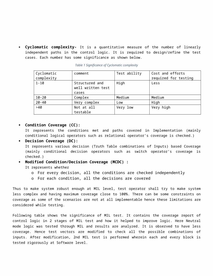
Cyclomatic complexity- It is a quantitative measure of the number of linearly independent paths in the control logic. It is required to design/refine the test cases. Each number has some significance as shown below.
Table 1 Significance of Cyclomatic complexity
Cyclomatic complexity comment Test ability Cost and efforts required for testing
1-10 Structured and well written test cases
High Less
10-20 Complex Medium Medium20-40 Very complex Low High>40 Not at all testable Very low Very high
Condition Coverage (CC): It represents the conditions met and paths covered in Implementation (mainly conditional logical operators such as relational operator’s coverage is checked.)
Decision Coverage (DC): It represents various decision (Truth Table combinations of Inputs) based Coverage (mainly conditional decision operators such as switch operator’s coverage is checked.)
Modified Condition/Decision Coverage (MCDC) : It represents whether
o For every decision, all the conditions are checked independentlyo For each condition, all the decisions are covered
Thus to make system robust enough at MIL level, test operator shall try to make system less complex and having maximum coverage close to 100%. There can be some constraints on coverage as some of the scenarios are not at all implementable hence these limitations are considered while testing.
Following table shows the significance of MIL test. It contains the coverage report of control logic in 2 stages of MIL test and how it helped to improve logic. Here Neutral mode logic was tested through MIL and results are analyzed. It is observed to have less coverage. Hence test vectors are modified to check all the possible combinations of inputs. After modification, 2nd MIL test is performed wherein each and every block is tested rigorously at Software level.
Table 2 Comparison of MIL test before and after test vector modification
MIL 1st test MIL 2nd test
No. of test cases-20 No. of test cases-31
Here using road data, all the input and output parameters for MIL test are identified in the form of test vectors and test was performed. 20 test cases were present earlier but MCDC coverage was 78% only. Hence test cases are analyzed and modified. Now 11 more test cases are added which resulted into MCDC coverage increased to 92%.Due to some feasibility limitations, 92% is the maximum coverage for neutral mode which is achieved using front loading in MIL.
Model-In-Loop test mainly has following advantages.
1. System and subsystem level tests are possible hence checking robustness of algorithm. 2. Coverage report tests the logic thoroughly hence system is tested at very high level except hardware
level limitations which are tested in Hardware-In-Loop test.
HARDWARE IN LOOP TESTING (HIL)
An early stage verification and validation of the critical functionalities of a Mild Hybrid Vehicle Control Algorithm is much reasonable than direct on-vehicle testing which involves high cost, risks and limitation in some extent. Calibration and validation of control algorithm on vehicle with lots of powertrain and other ECUs are always quite hectic and time consuming. So it’s pretty acceptable not only to mature the complete functionality of control algorithm but also check the hardware compatibility even before the actual vehicle is built and tested on road with this algorithm.
CONVENTIONAL APPROACH- As a conventional process, HIL is done using a plant model of the whole vehicle where every component is modeled and along with control algorithm, the vehicle performance is also tested.
Figure 3 Conventional Test Process
EXAMPLE OF CONVENTIONAL APPROACH- As example, for a basic EMS (Engine Management System) ECU test, detailed engine plant model is built and the driver inputs given to the EMS and engine plant model are normally Accelerator Pedal, Brake Pedal, Clutch Position and the Gear Position.
The main outputs from the plant model will be Engine Speed and Engine Torque which is fed to the EMS and accordingly EMS controls the valves and the injectors. It is very important in this case to have a detailed plant model to evaluate not only the EMS control algorithm but also to check the engine performance. By controlling the valves and injectors, engine performance will also be evaluated.
OUR APPROACH, WHY CONVENTIONAL APPROACH IS NOT FOLLOWED-In Mild Hybrid vehicle, engine is main driving source and electric machine is used as a secondary source. This electric machine is used for hybrid functions namely Stop-Start, Torque Assist, Generation and Recuperation function. So in brief, compare to engine, electric machine alone does not play major role in overall vehicle system.
During initial vehicle performance simulation using AVL cruise, it was analyzed that the ISG power and engine power ratio is so high that addition of ISG cannot effect vehicle performance.
Previously, during vehicle level simulation in AVL Cruise, the analysis showed that most of the fuel improvement, almost 60 percent, was achieved only from Auto Start Stop functionality. Which doesn’t affect the vehicle performance. The rest improvement was achieved from torque boost and regeneration.
During this simulation, a crude map based model of Battery and Motor was used to get the values for input vectors like Battery Current and Battery SoC for HIL testing using NEDC and MDC cycle.
On the other hand functionality of the control algorithm was very critical in our case as we had to achieve our target with such small ISG.
The three functions, i.e. Auto Start –Stop, Torque Assist and Regeneration of the was segregated into different states like Boost, Passive Assist, Generation, Recuperation, Coasting Down etc. So controlling of critical parameters like Voltage set point or torque demand at précised time was very important in this case.
Figure 4 Hybrid Modes based upon Engine speed & Torque graph
It can be seen from the above figure that in different vehicle speed and torque demand, the vehicle states were different. But based on the vehicle state, the ISG (Integrated Starter Generator) will be controlled with same parameters but different values. For example, though the vehicle may have Generation, Recuperation or Coasting Down mode, the ISG will be in Generation mode in all three cases. But the voltage set point level will be different for all three cases.Basically, this depicts that the functionality test of the system was much important than the performance test.
So basically, in conventional approach, the test system architecture is different as the aim is also different. In our program, i.e. in Mild Hybrid Control Algorithm Development, we realized, we only need to test the functionality of the Hybrid Control Algorithm. Making own test cases using all test vectors is always time consuming and hectic. It also doesn’t ensure all possible test scenarios. So to ensure it, we fed the logged data of chassis dyno which was obtained in NEDC and MDC cycles.
Figured out parameters, which can be logged directly from vehicle and can be fed to the control algorithm to make it functionality robust. Example- Engine Speed, ISG Speed, Battery SOC, Battery Current, Coolant Temperature etc.
To cover almost all possible conditions, huge database was created with those signals, which has been logged with conventional vehicle during chassis dyno test in NEDC and MDC cycles and outdoor testing also.
Figure 5 Test process followed during testing
This database was put into a .csv file which was used to create the stimulus profile in NI VeriStand to feed it to the control algorithm.
The control algorithm was flashed into the open ECU (Electronic Control Unit) and provided all type of communications like CAN, LIN and digital I/Os to build up a real vehicle scenario.
The host PC used to trigger tests and PXI 8119 used to do the real time processing of the data. These vehicle data was fed to the ECU through CAN, LIN and Digital input signals and the output from the control
algorithm was received to the PXI through CAN and compared with the expected output for each case or scenario.
TEST RIG SYSTEM ARCHITECTURE - To do the Hardware in Loop test by using real time road data as input to the control algorithm NI PXI 8119 has been used as a real time processor. It consists of-
CAN Chassis (NI PXI 8512) with two CAN ports, Industrial Digital I/O chassis (NI PXI 6514), Fault insertion Unit (NI PXI 2510) and LIN Chassis (NI PXI 8516) which is also having two LIN ports.
The Hybrid Control Unit or Device under Test communicates with ECUs like Engine Management System, Vehicle ECU through CAN and Motor Control Unit through LIN. It also has seven digital inputs and outputs.
TEST VECTORS USED- To avoid the use of plant model, which normally use driver inputs as input vectors, test vectors used in this approach, were logged from conventional vehicle during chassis dyno and road test and mapped with control logic input. In the following diagram, the difference between input test vectors of conventional test process using plant model and the input test vectors used in our system has been showed-
Table 3 Comparative Example of Test Vectors for Conventional Process and Front Loading Approach
Important Input Test Vectors in Conventional Test Important Input Test Vectors in this approach
Accelerator Pedal Position Brake Pedal Position Clutch Pedal Position Gear Position
Battery Current Battery State of Charge Accelerator Pedal Position Brake Press State Engine Speed Vehicle Speed Clutch Pedal State
It can be observed that parameters like Vehicle Speed, Engine Speed are not conventional input vectors for HIL, but in our case, we used it to avoid the Plant Model & thus reducing the time and cost by using test data.
CONCLUSION-
A typical development process starts with requirement finalization to meet the target, followed by decision sheet, vehicle performance analysis, component sizing with numerous iterations, control algorithm development, Model in Loop testing and validation, Hardware in Loop testing and validation and then chassis dyno and on road validation and calibration. For functionality testing of control algorithm and verify it with all possible way, front loading approach described in this literature can be helpful to drastically reduce the effort and the time irrespective of any vehicle architecture. This ensures the robustness of the control algorithm and the prototyped ECU at very early stage even before going on road.
Figure 6 Projected Timeline with conventional process to be followed for the same project
Figure 7 Actual timeline which was followed after taking decision of Data Front-Loading
If we go through both the timeline, it can be seen that the overall timeline for the project was reduced by almost three months in actual. That’s because of maturity level achieved within HIL was almost in a very good level. Eventually for calibration, chassis dyno and on road test the timeline was reduced and drastically.
ACKNOWLEDGMENTS
We acknowledge support from Mr. Chandrakant Awate, Mr. Gaurav Sadekar and Mr. Tushar Chodvadiya, as they were the integral part of the whole process of the Mild Hybrid Control Algorithm Development. We also acknowledge National Instruments for their immense support to set up the test rig and other requirements.
REFERENCES
1. A Cost Effective and Optimal Energy Management Strategy for Hybrid Electric Vehicles (HEV) based on Emission Analysis; Sachin P. Pandit, Senior Technical Leader – Revolo Hybrid Program, KPIT Technologies Limited
2. Document on test method, testing equipment and related procedures for testing type approval and conformity of production (COP) of vehicles for emission as per central motor vehicle (CMV) rules 115, 116 and 126. Document number: MoRT/CMVR/TAP-115/116
3. National Instruments Web Support.4. Chassis Dyno report of Conventional Powertrain in Aria, Tata Motors Limited.5. https://www.avl.com/documents/10138/0/MoBEO_Juventus_Stadium_Presentation.pdf/ad64db14-0fae-4470-
a0cf-bc93592513bf
CONTACT
Mr. Subhojit Sarkar (M-Tech, Power Electronics and Drives, NITW)
Figure 1 Overview of Front Loading Approach...................................................................................................................... 1Figure 2 Model-In-Loop test platform preparation................................................................................................................. 3Figure 3 Conventional Test Process..................................................................................................................................... 5Figure 4 Hybrid Modes based upon Engine speed & Torque graph......................................................................................6Figure 5 Test process followed during testing....................................................................................................................... 7Figure 6 Projected Timeline with conventional process to be followed for the same project.................................................8Figure 7 Actual timeline which was followed after taking decision of Data Front-Loading.....................................................9
Table 1 Significance of Cyclomatic complexity...................................................................................................................... 4Table 2 Comparison of MIL test before and after test vector modification.............................................................................4Table 4 Comparative Example of Test Vectors for Conventional Process and Front Loading Approach..............................8