EE2351 POWER SYSTEM ANALYSIS SCE Page 1 of 106 DEPARTMENT OF EEE A Course Material on EE2351 POWER SYSTEM ANALYSIS By Mr. K. ESWARAMOORTHY ASSISTANT PROFESSOR DEPARTMENT OF ELECTRICAL AND ELECTRONICS ENGINEERING SASURIE COLLEGE OF ENGINEERING VIJAYAMANGALAM – 638 056
Transcript
EE2351 POWER SYSTEM ANALYSIS
SCE Page 1 of 106 DEPARTMENT OF EEE
A Course Material on
EE2351 POWER SYSTEM ANALYSIS
By
Mr. K. ESWARAMOORTHY
ASSISTANT PROFESSOR
DEPARTMENT OF ELECTRICAL AND ELECTRONICS ENGINEERING
SASURIE COLLEGE OF ENGINEERING
VIJAYAMANGALAM – 638 056
EE2351 POWER SYSTEM ANALYSIS
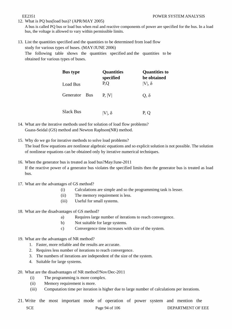
SCE Page 2 of 106 DEPARTMENT OF EEE
QUALITY CERTIFICATE
This is to certify that the e-course material
Subject Code : EE2351
Subject Name : POWER SYSTEM ANALYSIS
Class : THIRD YEAR EEE
being prepared by me and it meets the knowledge requirement of the university curriculum.
Signature of the Author
Name : K.Eswaramoorthy
Designation : Assistant Professor
This is to certify that the course material being prepared by Mr. K.Eswaramoorthy is of adequate quality. She has
referred more than five books among them minimum one is from aboard author.
Signature of HD
Name : S.Sriram
SEAL
EE2351 POWER SYSTEM ANALYSIS
SCE Page 3 of 106 DEPARTMENT OF EEE
EE2351 POWER SYSTEM ANALYSIS L T P C 3 1 0 4
AIM
To understand the necessity and to become familiar with the modeling of power system and
components. And to apply different methods to analyze power system for the purpose of system
planning and operation.
OBJECTIVES
To model the power system under steady state operating condition. To apply efficient
numerical methods to solve the power flow problem.
To model and analyses the power systems under abnormal (or) fault conditions.
To model and analyses the transient behavior of power system when it is subjected to a
fault.
UNIT I INTRODUCTION 9
Modern power system (or) electric energy system - Analysis for system planning and operational
studies – basic components of a power system. Generator models - transformer model
–transmission system model - load representation. Single line diagram – per phase and per unit
representation – change of base. Simple building algorithms for the formation of Y-Bus matrix
and Z Bus matrix.
UNIT II POWER FLOW ANALYSIS 9
Importance of power flow analysis in planning and operation of power systems. Statement of
power flow problem - classification of buses into P-Q buses, P-V (voltage-controlled) buses and
slack bus. Development of Power flow model in complex variables form and polar variables
form. Iterative solution using Gauss-Seidel method including Q-limit check for
voltage-controlled buses – algorithm and flow chart. Iterative solution using Newton-Rap son
(N-R) method (polar form) including Q-limit check and bus switching for voltage-controlled
buses - Jacobian matrix elements – algorithm and flow chart. Development of Fast Decoupled
Power Flow (FDPF) model and iterative solution – algorithm and flowchart; Comparison of the
three methods.
UNIT III FAULT ANALYSIS – BALANCED FAULTS 9
Importance short circuit (or) for fault analysis - basic assumptions in fault analysis of power
systems. Symmetrical (or) balanced three phase faults – problem formulation – fault analysis
using Z-bus matrix – algorithm and flow chart. Computations of short circuit capacity, post fault
voltage and currents.
UNIT IV FAULT ANALYSIS – UNBALANCED FAULTS 9
Introduction to symmetrical components – sequence impedance – sequence networks
–representation of single line to ground, line to line and double line to ground fault conditions.
Unbalanced fault analysis - problem formulation – analysis using Z-bus impedance matrix
–(algorithm and flow chart.).
EE2351 POWER SYSTEM ANALYSIS
SCE Page 4 of 106 DEPARTMENT OF EEE
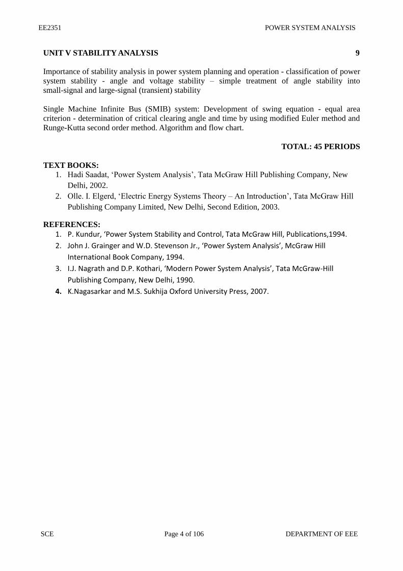
UNIT V STABILITY ANALYSIS 9
Importance of stability analysis in power system planning and operation - classification of power
system stability - angle and voltage stability – simple treatment of angle stability into
small-signal and large-signal (transient) stability
Single Machine Infinite Bus (SMIB) system: Development of swing equation - equal area
criterion - determination of critical clearing angle and time by using modified Euler method and
Runge-Kutta second order method. Algorithm and flow chart.
TOTAL: 45 PERIODS
TEXT BOOKS:
1. Hadi Saadat, ‘Power System Analysis’, Tata McGraw Hill Publishing Company, New
Delhi, 2002.
2. Olle. I. Elgerd, ‘Electric Energy Systems Theory – An Introduction’, Tata McGraw Hill
Publishing Company Limited, New Delhi, Second Edition, 2003.
REFERENCES:
1. P. Kundur, ‘Power System Stability and Control, Tata McGraw Hill, Publications,1994.
2. John J. Grainger and W.D. Stevenson Jr., ‘Power System Analysis’, McGraw Hill
International Book Company, 1994.
3. I.J. Nagrath and D.P. Kothari, ‘Modern Power System Analysis’, Tata McGraw-Hill
Publishing Company, New Delhi, 1990.
4. K.Nagasarkar and M.S. Sukhija Oxford University Press, 2007.
EE2351 POWER SYSTEM ANALYSIS
SCE Page 5 of 106 DEPARTMENT OF EEE
LIST OF CONTENTS
SI.NO CONTENT PAGE
NO
UNIT – I INTRODUCTION
1.1 INTRODUCTION 8
1.2 MODERN POWER SYSTEM (OR) ELECTRIC ENERGY SYSTEM 9
1.3 ANALYSIS FOR SYSTEM PLANNING AND OPERATIONAL
STUDIES 10
1.4 BASIC COMPONENTS OF A POWER SYSTEM. 11
1.5 GENERATOR MODELS 12
1.6 TRANSFORMER MODEL 12
1.7 TRANSMISSION SYSTEM MODEL 15
1.8 LOAD REPRESENTATION 18
1.9 SINGLE LINE DIAGRAM 19
1.10 PER PHASE AND PER UNIT REPRESENTATION 19
1.11 CHANGE OF BASE 20
1.12 SIMPLE BUILDING ALGORITHMS FOR THE FORMATION OF
Y-BUS MATRIX AND Z BUS MATRIX. 21
1.13 EXERCISES FOR PRACTICE 28
UNIT – II LOAD FLOW ANALYSIS
2.1 IMPORTANCE OF POWER FLOW ANALYSIS IN PLANNING AND
OPERATION OF POWER SYSTEMS. 30
2.2 STATEMENT OF POWER FLOW PROBLEM 30
2.3 CLASSIFICATION OF BUSES 30
2.4 ITERATIVE SOLUTION USING GAUSS-SEIDEL METHOD 31
2.5 ITERATIVE SOLUTION USING NEWTON-RAPHSON 35
2.6 JACOBIAN MATRIX ELEMENTS 39
2.7 FAST DECOUPLED POWER FLOW (FDPF) MODEL 43
2.8 COMPARISON OF THE THREE METHODS 44
UNIT – III FAULT ANALYSIS – BALANCED FAULTS
3.1 IMPORTANCE SHORT CIRCUIT (OR) FOR FAULT ANALYSIS 45
3.2 BASIC ASSUMPTIONS IN FAULT ANALYSIS OF POWER 45
EE2351 POWER SYSTEM ANALYSIS
SCE Page 6 of 106 DEPARTMENT OF EEE
SYSTEMS. SYMMETRICAL (OR) BALANCED THREE PHASE
FAULTS
3.3 PROBLEM FORMULATION 46
3.4 FAULT ANALYSIS USING Z-BUS MATRIX – ALGORITHM 48
3.5 COMPUTATIONS OF SHORT CIRCUIT CAPACITY, POST FAULT
VOLTAGE AND CURRENTS. 49
UNIT – IV FAULT ANALYSIS – UN-BALANCED FAULTS
4.1 INTRODUCTION TO SYMMETRICAL COMPONENTS 62
4.2 SEQUENCE IMPEDANCES – SEQUENCE NETWORKS 63
4.3 REPRESENTATION OF SINGLE LINE TO GROUND, LINE TO
LINE AND DOUBLE LINE TO GROUND FAULT CONDITIONS 66
4.4 UNBALANCED FAULT ANALYSIS PROBLEM FORMULATION 68
UNIT V STABILITY ANALYSIS
5.1 IMPORTANCE OF STABILITY ANALYSIS IN POWER SYSTEM
PLANNING AND OPERATION 77
5.2 CLASSIFICATION OF POWER SYSTEM STABILITY 77
5.3 ANGLE AND VOLTAGE STABILITY 78
5.4 SINGLE MACHINE INFINITE BUS (SMIB) SYSTEM:
DEVELOPMENT OF SWING EQUATION 80
5.5 DETERMINATION OF CRITICAL CLEARING ANGLE AND TIME 87
EE2351 POWER SYSTEM ANALYSIS
SCE Page 7 of 106 DEPARTMENT OF EEE
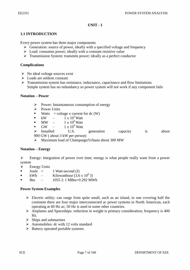
UNIT - 1
1.1 INTRODUCTION
Every power system has three major components
Generation: source of power, ideally with a specified voltage and frequency
Load: consumes power; ideally with a constant resistive value
Transmission System: transmits power; ideally as a perfect conductor
Complications
No ideal voltage sources exist
Loads are seldom constant
Transmission system has resistance, inductance, capacitance and flow limitations
Simple system has no redundancy so power system will not work if any component fails
Notation – Power
Power: Instantaneous consumption of energy
Power Units
Watts = voltage x current for dc (W)
kW – 1 x 10³ Watt
MW – 1 x 10⁶ Watt
GW – 1 x 10⁹ Watt
Installed U.S. generation capacity is about
900 GW ( about 3 kW per person)
Maximum load of Champaign/Urbana about 300 MW
Notation – Energy
Energy: Integration of power over time; energy is what people really want from a power
system
Energy Units
Joule = 1 Watt-second (J)
kWh – Kilowatthour (3.6 x 10⁶ J)
Btu – 1055 J; 1 MBtu=0.292 MWh
Power System Examples
Electric utility: can range from quite small, such as an island, to one covering half the
continent there are four major interconnected ac power systems in North American, each
operating at 60 Hz ac; 50 Hz is used in some other countries.
Airplanes and Spaceships: reduction in weight is primary consideration; frequency is 400
Hz.
Ships and submarines
Automobiles: dc with 12 volts standard
Battery operated portable systems
EE2351 POWER SYSTEM ANALYSIS
SCE Page 8 of 106 DEPARTMENT OF EEE
1.2 MODERN POWER SYSTEM (OR) ELECTRIC ENERGY SYSTEM
Over view of power system analysis
Power system consists of
Generation Transmission Distribution system
Components of power system.
Components of power system are
Generators
Transformers
Transmission Lines
Distribution Lines
Loads
Compensating Devices - Shunt compensators , Series compensators, Static VAR
compensators
Definition of Power System
The evalution of Power system is called as Power system analysis
Functions of Power System analysis:
To maintain the voltage at various buses real and reactive power flow between buses
To design the circuit breakers
To plan the future expansion of existing system
To analyze the system under different fault conditions (three phase fault, L-G, L-L, L-L-G
faults)
To study the ability of the system for large disturbance (Sudden application of the large
load)
To study the ability of the system for small disturbance
Natural Sources
Coal
Water flow
Uranium & Thorium
Fossil Fuel
Wind
Tidal
Solar
Bio-Gas
EE2351 POWER SYSTEM ANALYSIS
SCE Page 9 of 106 DEPARTMENT OF EEE
1.3. ANALYSIS FOR SYSTEM PLANNING AND OPERATIONAL STUDIES
Needs for system analysis in planning and operation of power system
Planning and operation of power system - Operational planning covers the whole period ranging
from the incremental stage of system development
The system operation engineers at various points like area, space, regional & national load
dispatch of power
Power balance equation PD =
N
i
PGi1
This equation is satisfied it gives good economy ans
security
Power system planning and operational analysis covers the maintenance of generation,
transmission and distribution facilities
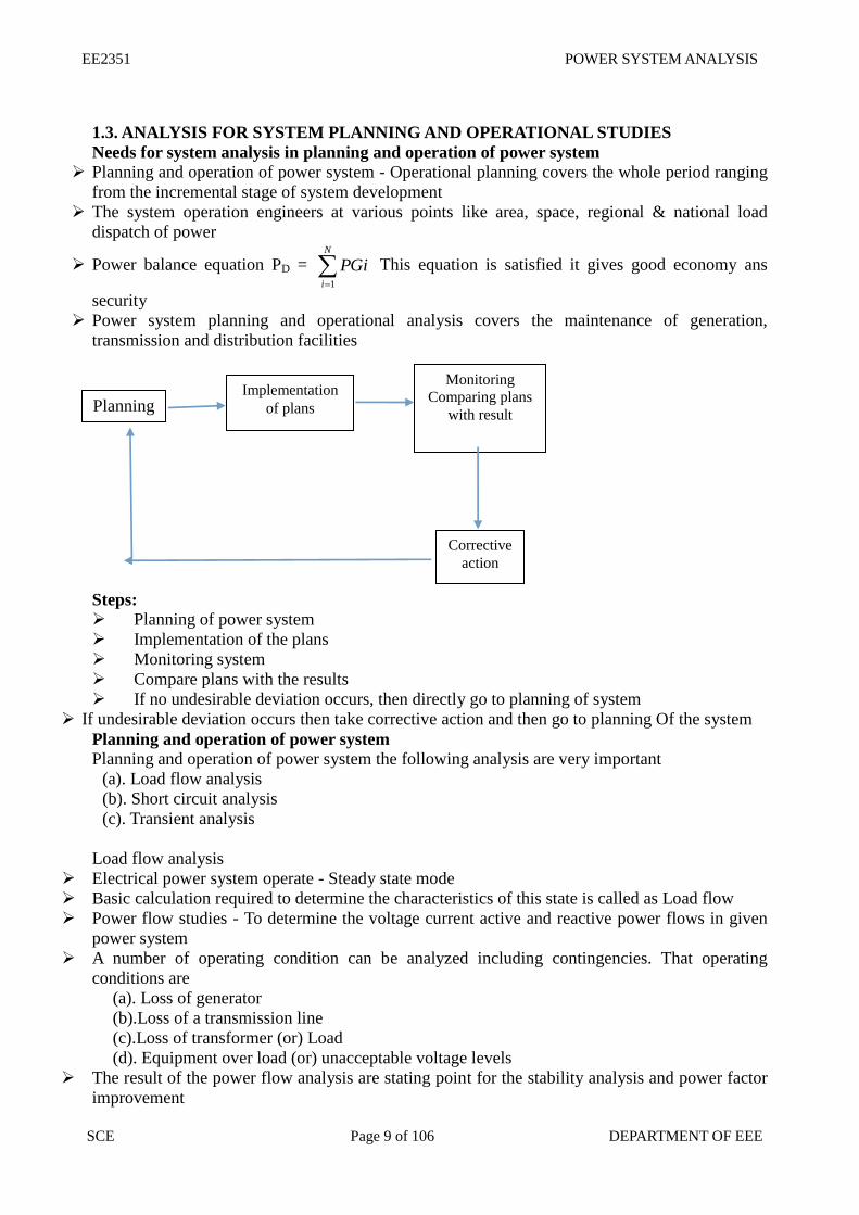
Steps:
Planning of power system
Implementation of the plans
Monitoring system
Compare plans with the results
If no undesirable deviation occurs, then directly go to planning of system
If undesirable deviation occurs then take corrective action and then go to planning Of the system
Planning and operation of power system
Planning and operation of power system the following analysis are very important
(a). Load flow analysis
(b). Short circuit analysis
(c). Transient analysis
Load flow analysis
Electrical power system operate - Steady state mode
Basic calculation required to determine the characteristics of this state is called as Load flow
Power flow studies - To determine the voltage current active and reactive power flows in given
power system
A number of operating condition can be analyzed including contingencies. That operating
conditions are
(a). Loss of generator
(b).Loss of a transmission line
(c).Loss of transformer (or) Load
(d). Equipment over load (or) unacceptable voltage levels
The result of the power flow analysis are stating point for the stability analysis and power factor
improvement
Planning Implementation
of plans
Monitoring
Comparing plans
with result
Corrective
action
EE2351 POWER SYSTEM ANALYSIS
SCE Page 10 of 106 DEPARTMENT OF EEE
Load flow study is done during the planning of a new system or the extension of an existing one
Short circuit studies
To determine the magnitude of the current flowing through out the power system at various time
intervals after fault
The objective of short circuit analysis - To determine the current and voltages at different
location of the system corresponding to different types of faults
(a). Three phase to ground fault
(b). Line to ground fault
(c). Line to line fault
(d). Double line to ground fault
(e). Open conductor fault
Transient stability analysis
The ability of the power system consisting of two (or) more generators to continue to operate
after change occur on the system is a measure of the stability
In power system the stability depends on the power flow pattern generator characteristics system
loading level and the line parameters
1.4. BASIC COMPONENTS OF A POWER SYSTEM.
Structure of Power system
Fig 1.1 Structure of Power System
Components of power system
Components of power system are in Fig 1.1
Generators - Convert mechanical energy in to electrical energy
Transformers - Transfer Power or energy from one circuit to another circuit with out change in
frequency
Transmission Lines - Transfer power from one place another place
Control Equipment: Used for protection purpose
EE2351 POWER SYSTEM ANALYSIS
SCE Page 11 of 106 DEPARTMENT OF EEE
1.5 CONCEPT OF REAL AND REACTIVE POWER
Let ‘V’ be the Instantaneous voltage
Let ‘i’ be the Instantaneous current
V = Vm sin ωt
I = im sin (ωt - Φ)
Radian frequency ω = 2Πf
Transmitter power P = V i
= Vm sin ωt * im sin (ωt - Φ)
= 2
Vmim(cos Φ - cos (2ωt - Φ)
RMS value of voltage |V| = 414.1
maxV
RMS value of voltage |i| = 414.1
maxi
P = |V| |i| [cos Φ - cos (2ωt - Φ)]
=|V| |i| cos Φ - |V| |i| cos (2ωt - Φ)
= |V| |i| cos Φ - |V| |i| (cos 2ωt cos Φ + sin 2ωt sin Φ)
= |V| |i| cos Φ (1 - cos 2ωt) - |V| |i| sin Φ sin 2ωt
P = P (1 -cos 2ωt) - Q sin 2ωt
Where active or useful or real power P=|V| |i| cos Φ watts
Non - active (or) Reactive power Q = |V| |i| sin Φ VAR
Table 1.1 Phasor Relation with Real and reactive power
Inductive Load - Absorbs reactive power
Capacitive Load - Generate reactive power
Apparent Power:The product of RMS value of voltage and current
1.6 MODELING OF COMPONENTS FOR LOAD FLOW ANALYSIS
Generator models
Generators:
The thevenins equivalent circuit of the generator i.e. The voltage source in series with the
thevenins equivalent impedance. Z = R + jX
Types of
load
Phasor Diagram Angle Real power Reactive
power
R Load Φ = 0 P > 0 Q = 0
L Load
V
Φ = 90 (lags) P = 0 Q > 0
C Load
I Φ = 90
(Leads) P = 0 Q < 0
RL Load
V 0 < Φ < 90 P > 0 Q > 0
RC Load
I -90 < Φ < 0 P > 0 Q < 0
EE2351 POWER SYSTEM ANALYSIS
SCE Page 12 of 106 DEPARTMENT OF EEE
Fig 1.2 Basic model Fig 1.3 Equivalent circuit
The Norton form equivalent circuit of the generator i.e. The current source in parallel with the
admittance
.
Fig 1.4 Norton Equaivalent circuit
Transformer model
Transmission system model
Transmission Line
Transmission line are modelled as (i). Short line model (ii). Medium line model (iii). Long line
model
(i). Short line model : Resistance & inductance are assumed to be lumped
EE2351 POWER SYSTEM ANALYSIS
SCE Page 13 of 106 DEPARTMENT OF EEE
Fig 1.7 Equivalent transmission line model ABCD parameters
Ir
Vr
DC
BA
Is
Vs
Medium line model (lines between 80 to 250km)
Resistance &inductance are assumed to be lumped &the total shunt admittance is divided in to
two equal parts & placed at the receiving and sending ends.
The Π model
Fig 1.8 Pi model
Ir
Vr
DC
BA
Is
Vs
X = Lω
Y/2 = Cω/2
A = 1+ZY/2
B=Z
C=Y(1+ZY/4)
D=1+ZY/4
Long line model (lines above 250)
Z’=Z sinhγL / γ L
Y’/2 = 1/Zc tan h (γL/2)
Fig 1.9 Medium line model
EE2351 POWER SYSTEM ANALYSIS
SCE Page 14 of 106 DEPARTMENT OF EEE
Shunt Elements:
The shunt capacitor is connected to bus i. If S is MVAR rating of shunt capacitor. So is base
MVA admittance P.u. Y P.u. = 0+jS/S0
Fig 1.10 Shunt Elements
Shunt reactors is connected io bus i. If S is MVAR rating of shunt capacitor. So is base MVA
admittance P.u. Y P.u. = 0-jS/S0
Load representation
Load: Load is represented by a constant power representation. Both MW (P) & MVAR (Q) -
constant
1.7. SINGLE LINE DIAGRAM
Single line diagram
In general electrical power systems are represented by a one line diagram (or) single line
diagram
A single line diagram of a power system shows the main connections & arrangements of
components in a simplified manner
Pictorial representation of the entire power system from generating end to the consumer
premises is known as single line diagram
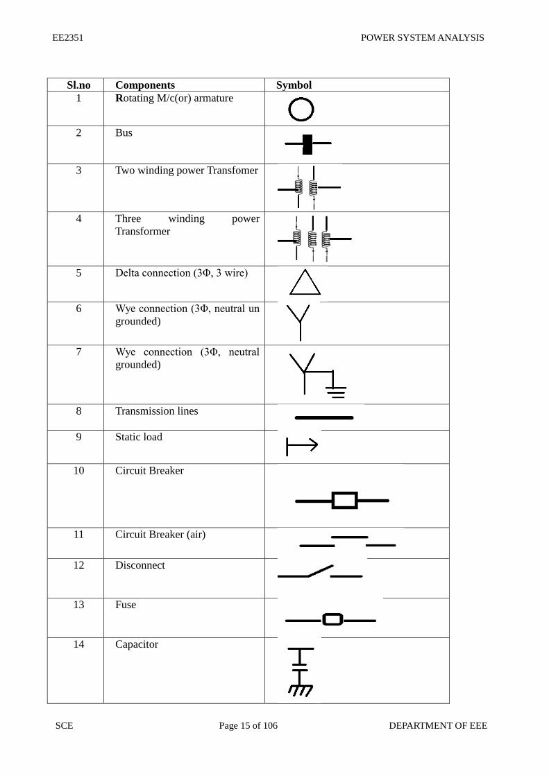
Standard symbols
Ir
Vr
llZc
lZcl
Is
Vs
coshsinh/1
sinhcosh
EE2351 POWER SYSTEM ANALYSIS
SCE Page 15 of 106 DEPARTMENT OF EEE
Sl.no Components Symbol
1 Rotating M/c(or) armature
2 Bus
3 Two winding power Transfomer
4 Three winding power
Transformer
5 Delta connection (3Φ, 3 wire)
6 Wye connection (3Φ, neutral un
grounded)
7 Wye connection (3Φ, neutral
grounded)
8 Transmission lines
9 Static load
10 Circuit Breaker
11 Circuit Breaker (air)
12 Disconnect
13 Fuse
14 Capacitor
EE2351 POWER SYSTEM ANALYSIS
SCE Page 16 of 106 DEPARTMENT OF EEE
15 Current transformer
16 Potential transformer
17 Lighting arrester
Single Line diagram of an Electrical system
One line diagram of a very simple power system
Two generators one grounded through a reactor and one through a resister connected to a bus and
through a step up transformer to a transmission lines
Another generator grounded a reactor is connected a bus and through a transformer to the
opposite end of the transmission line
A load is connected to each bus
On the diagram information about the loads the ratings of the generators and transformers and
reactance of different components of the circuit is often given
It is important to know the location of points where a system is connected to ground to calculate
the amount of current flowing when an unsymmetrical fault involving ground occur
Equivalent circuit for various power system components:
(i). Generators
(ii). Transmission lines
EE2351 POWER SYSTEM ANALYSIS
SCE Page 17 of 106 DEPARTMENT OF EEE
(iii). Transformer
(iv). Static load
(v). Rotating load (motor)
1.8 IMPEDANCE DIAGRAM
The impedance diagram on single-phase basis for use under balanced conditions can be easily
drawn from the SLD. The following assumptions are made in obtaining the impedance diagrams.
Assumptions:
1. The single phase transformer equivalents are shown as ideals with impedance on appropriate
side (LV/HV),
2. The magnetizing reactance of transformers are negligible,
3. The generators are represented as constant voltage sources with series resistance or
reactance,
4. The transmission lines are approximated by their equivalent -Models,
5. The loads are assumed to be passive and are represented by a series branch of
resistance or reactance and
6. Since the balanced conditions are assumed, the neutral grounding impedance do not
appear in the impedance diagram.
EE2351 POWER SYSTEM ANALYSIS
SCE Page 18 of 106 DEPARTMENT OF EEE
Example system
As per the list of assumptions as above and with reference to the system of figure 2, the impedance
diagram can be obtained as shown in figure
1.9 REACTANCE DIAGRAM
With some more additional and simplifying assumptions, the impedance diagram can be
simplified further to obtain the corresponding reactance diagram. The following are the
assumptions made.
Additional assumptions:
The resistance is often omitted during the fault analysis. This causes a very negligible error since,
resistances are negligible
Loads are Omitted
Transmission line capacitances are ineffective &
Magnetizing currents of transformers are neglected.
Example system
as per the assumptions given above and with reference to the system of figure 2 and
Figure, the reactance diagram can be obtained as shown in figure
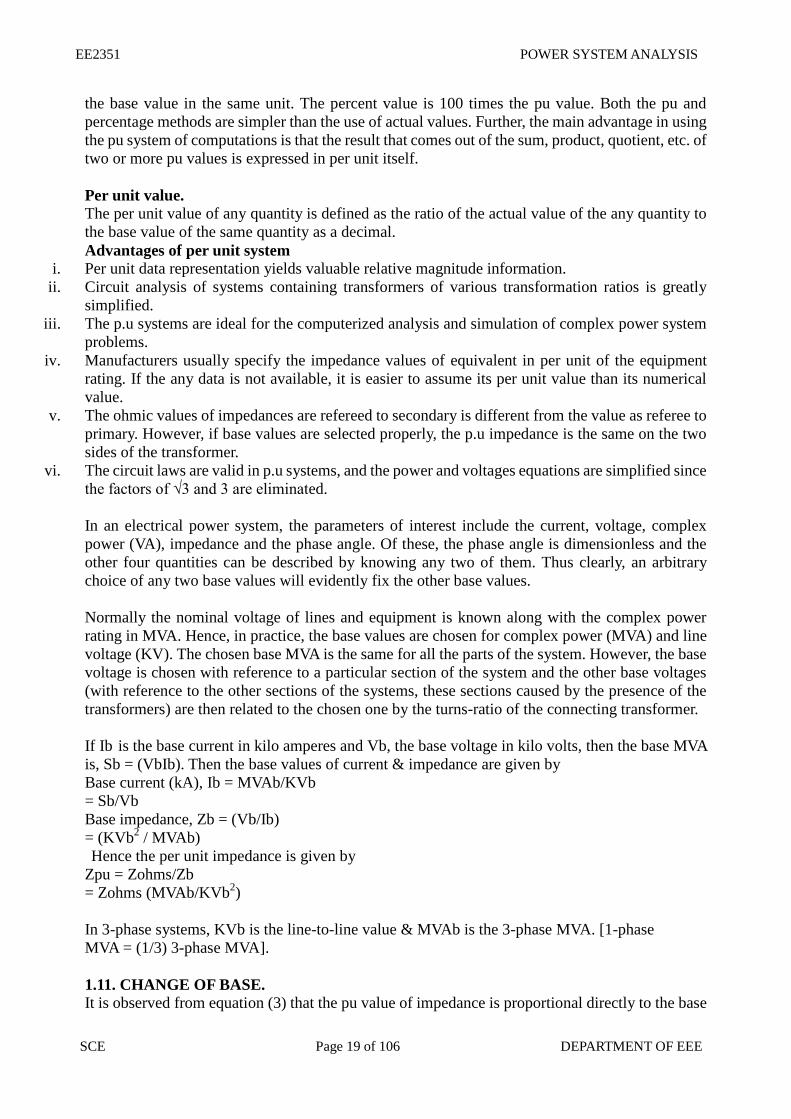
1.10.PER PHASE AND PER UNIT REPRESENTATION During the power system analysis, it is a usual practice to represent current, voltage, impedance,
power, etc., of an electric power system in per unit or percentage of the base or reference value of
the respective quantities. The numerical per unit (pu) value of any quantity is its ratio to a chosen
base value of the same dimension. Thus a pu value is a normalized quantity with respect to the
chosen base value.
Definition: Per Unit value of a given quantity is the ratio of the actual value in any given unit to
EE2351 POWER SYSTEM ANALYSIS
SCE Page 19 of 106 DEPARTMENT OF EEE
the base value in the same unit. The percent value is 100 times the pu value. Both the pu and
percentage methods are simpler than the use of actual values. Further, the main advantage in using
the pu system of computations is that the result that comes out of the sum, product, quotient, etc. of
two or more pu values is expressed in per unit itself.
Per unit value. The per unit value of any quantity is defined as the ratio of the actual value of the any quantity to
the base value of the same quantity as a decimal.
Advantages of per unit system i. Per unit data representation yields valuable relative magnitude information.
ii. Circuit analysis of systems containing transformers of various transformation ratios is greatly
simplified.
iii. The p.u systems are ideal for the computerized analysis and simulation of complex power system
problems.
iv. Manufacturers usually specify the impedance values of equivalent in per unit of the equipment
rating. If the any data is not available, it is easier to assume its per unit value than its numerical
value.
v. The ohmic values of impedances are refereed to secondary is different from the value as referee to
primary. However, if base values are selected properly, the p.u impedance is the same on the two
sides of the transformer.
vi. The circuit laws are valid in p.u systems, and the power and voltages equations are simplified since
the factors of √3 and 3 are eliminated.
In an electrical power system, the parameters of interest include the current, voltage, complex
power (VA), impedance and the phase angle. Of these, the phase angle is dimensionless and the
other four quantities can be described by knowing any two of them. Thus clearly, an arbitrary
choice of any two base values will evidently fix the other base values.
Normally the nominal voltage of lines and equipment is known along with the complex power
rating in MVA. Hence, in practice, the base values are chosen for complex power (MVA) and line
voltage (KV). The chosen base MVA is the same for all the parts of the system. However, the base
voltage is chosen with reference to a particular section of the system and the other base voltages
(with reference to the other sections of the systems, these sections caused by the presence of the
transformers) are then related to the chosen one by the turns-ratio of the connecting transformer.
If Ib is the base current in kilo amperes and Vb, the base voltage in kilo volts, then the base MVA
is, Sb = (VbIb). Then the base values of current & impedance are given by
Base current (kA), Ib = MVAb/KVb
= Sb/Vb
Base impedance, Zb = (Vb/Ib)
= (KVb2 / MVAb)
Hence the per unit impedance is given by
Zpu = Zohms/Zb
= Zohms (MVAb/KVb2)
In 3-phase systems, KVb is the line-to-line value & MVAb is the 3-phase MVA. [1-phase
MVA = (1/3) 3-phase MVA].
1.11. CHANGE OF BASE.
It is observed from equation (3) that the pu value of impedance is proportional directly to the base
EE2351 POWER SYSTEM ANALYSIS
SCE Page 20 of 106 DEPARTMENT OF EEE
MVA and inversely to the square of the base KV. If Zpunew is the pu impedance required to be
calculated on a new set of base values: MVAbnew & KVbnew from the already given per unit
impedance Zpuold, specified on the old set of base values, MVAbold & KVbold , then we have
Zpunew = Zpu old (MVAb new/MVAbold) (KVbold/KVbnew)2
On the other hand, the change of base can also be done by first converting the given pu impedance
to its ohmic value and then calculating its pu value on the new set of base values.
Merits and Demerits of pu System
Following are the advantages and disadvantages of adopting the pu system of
computations in electric power systems:
Merits:
The pu value is the same for both 1-phase and & 3-phase systems
The pu value once expressed on a proper base, will be the same when refereed to either side of the
transformer. Thus the presence of transformer is totally eliminated
The variation of values is in a smaller range 9nearby unity). Hence the errors
involved in pu computations are very less.
Usually the nameplate ratings will be marked in pu on the base of the name plate
ratings, etc.
Demerits:
If proper bases are not chosen, then the resulting pu values may be highly absurd (such as 5.8 pu,
-18.9 pu, etc.). This may cause confusion to the user. However, this problem can be avoided by
selecting the base MVA near the high-rated equipment and a convenient base KV in any section of
the system.
PU Impedance / Reactance Diagram
For a given power system with all its data with regard to the generators, transformers, transmission
lines, loads, etc., it is possible to obtain the corresponding impedance or
reactance diagram as explained above. If the parametric values are shown in pu on the
properly selected base values of the system, then the diagram is referred as the per unit
impedance or reactance diagram. In forming a pu diagram, the following are the
procedural steps involved:
1. Obtain the one line diagram based on the given data
2. Choose a common base MVA for the system
3. Choose a base KV in any one section (Sections formed by transformers)
4. Find the base KV of all the sections present
5. Find pu values of all the parameters: R,X, Z, E, etc.
6. Draw the pu impedance/ reactance diagram.
1.12 FORMATION OF Y BUS & Z BUS
The performance equations of a given power system can be considered in three different frames of
reference as discussed below:
Frames of Reference:
Bus Frame of Reference: There are b independent equations (b = no. of buses) relating the bus
vectors of currents and voltages through the bus impedance matrix and bus admittance matrix:
EBUS = ZBUS IBUS
IBUS = YBUS EBUS
EE2351 POWER SYSTEM ANALYSIS
SCE Page 21 of 106 DEPARTMENT OF EEE
Bus Frame of Reference: There are b independent equations (b = no. of buses) relating the bus
vectors of currents and voltages through the bus impedance matrix and bus admittance matrix:
EBUS = ZBUS IBUS
IBUS = YBUS EBUS
Branch Frame of Reference: There are b independent equations (b = no. of branches of a selected
Tree sub-graph of the system Graph) relating the branch vectors of currents and voltages through
the branch impedance matrix and branch admittance matrix:
EBR = ZBR IBR
IBR = YBR EBR
Loop Frame of Reference: There are b independent equations (b = no. of branches of a selected
Tree sub-graph of the system Graph) relating the branch vectors of currents and voltages through
the branch impedance matrix and branch admittance matrix:
ELOOP = ZLOOP ILOOP
ILOOP = YLOOP ELOOP
Of the various network matrices refered above, the bus admittance matrix (YBUS) and the bus
impedance matrix (ZBUS) are determined for a given power system by the rule of inspection as
explained next.
Rule of Inspection
Consider the 3-node admittance network as shown in figure5. Using the basic branch relation: I
= (YV), for all the elemental currents and applying Kirchhoff’s Current Law principle at the
nodal points, we get the relations as under:
At node 1: I1 =Y1V1 + Y3 (V1-V3) + Y6 (V1 – V2)
At node 2: I2 =Y2V2 + Y5 (V2-V3) + Y6 (V2 – V1)
At node 3: 0 = Y3 (V3-V1) + Y4V3 + Y5 (V3 – V2)
i. These are the performance equations of the given network in admittance form and they can be
represented in matrix form as:
In other words, the relation of equation (9) can be represented in the form IBUS = YBUS EBUS
Where, YBUS is the bus admittance matrix, IBUS & EBUS are the bus current and bus voltage
vectors respectively.
By observing the elements of the bus admittance matrix, YBUS of equation (9), it is observed
that the matrix elements can as well be obtained by a simple inspection of the given system
diagram:
Diagonal elements: A diagonal element (Yii) of the bus admittance matrix, YBUS, is equal to the
sum total of the admittance values of all the elements incident at the bus/node i,
EE2351 POWER SYSTEM ANALYSIS
SCE Page 22 of 106 DEPARTMENT OF EEE
Off Diagonal elements: An off-diagonal element (Yij) of the bus admittance matrix, YBUS, is
equal to the negative of the admittance value of the connecting element present between the
buses I and j, if any.
This is the principle of the rule of inspection. Thus the algorithmic equations for the rule of
inspection are obtained as:
Yij = - yij (j = 1,2,…….n)
For i = 1,2,….n, n = no. of buses of the given system, yij is the admittance of element connected
between buses i and j and yii is the admittance of element connected between bus i and ground
(reference bus).
Bus impedance matrix
In cases where, the bus impedance matrix is also required, then it cannot be formed by direct
inspection of the given system diagram. However, the bus admittance matrix determined by the
rule of inspection following the steps explained above, can be inverted to obtain the bus
impedance matrix, since the two matrices are inter-invertible.
Note: It is to be noted that the rule of inspection can be applied only to those power systems that
do not have any mutually coupled elements.
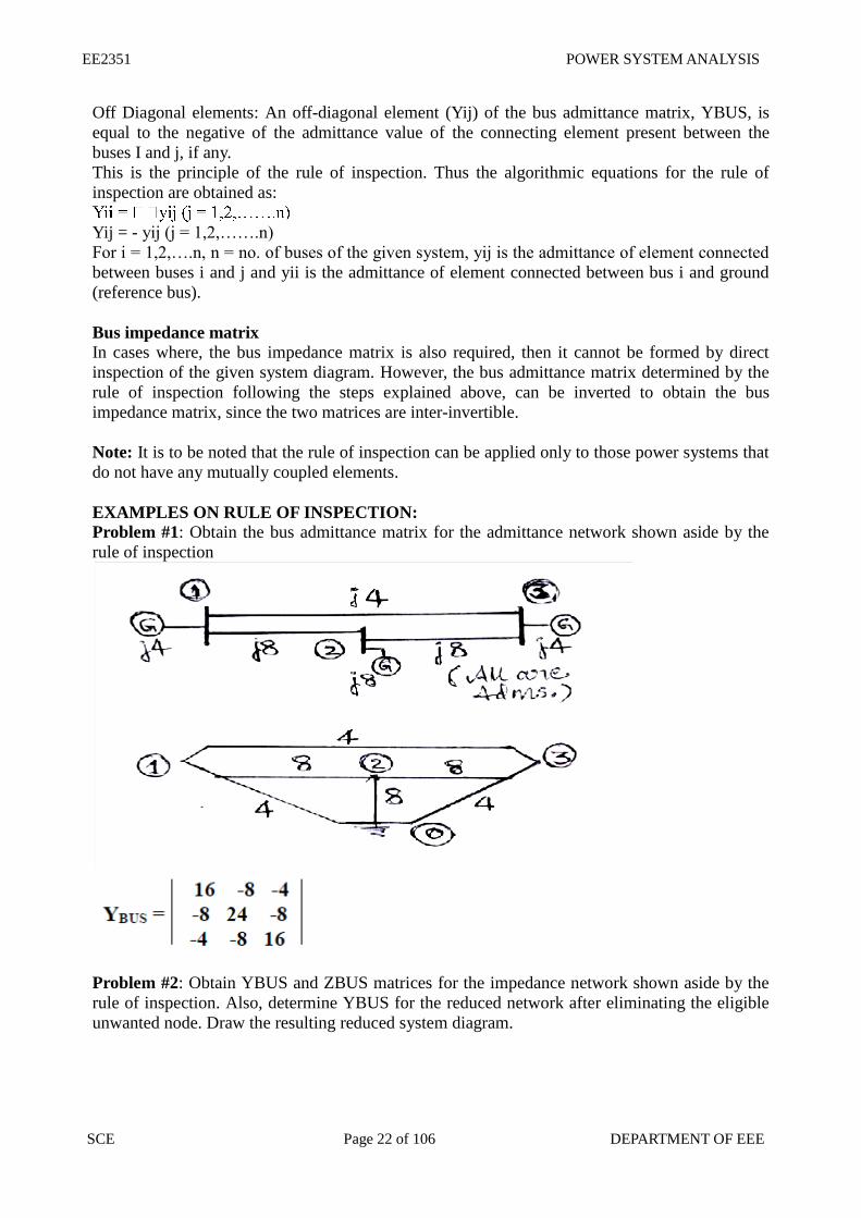
EXAMPLES ON RULE OF INSPECTION:
Problem #1: Obtain the bus admittance matrix for the admittance network shown aside by the
rule of inspection
Problem #2: Obtain YBUS and ZBUS matrices for the impedance network shown aside by the
rule of inspection. Also, determine YBUS for the reduced network after eliminating the eligible
unwanted node. Draw the resulting reduced system diagram.
EE2351 POWER SYSTEM ANALYSIS
SCE Page 23 of 106 DEPARTMENT OF EEE
EXAMPLES ON PER UNIT ANALYSIS:
Problem #1:
Two generators rated 10 MVA, 13.2 KV and 15 MVA, 13.2 KV are connected in parallel to a bus
bar. They feed supply to 2 motors of inputs 8 MVA and 12 MVA respectively.
The operating voltage of motors is 12.5 KV. Assuming the base quantities as 50 MVA, 13.8 KV,
draw the per unit reactance diagram. The percentage reactance for generators is 15% and that for
motors is 20%.
Solution:
The one line diagram with the data is obtained as shown in figure
EE2351 POWER SYSTEM ANALYSIS
SCE Page 24 of 106 DEPARTMENT OF EEE
EXAMPLES ON PER UNIT ANALYSIS:
Problem #1:
Two generators rated 10 MVA, 13.2 KV and 15 MVA, 13.2 KV are connected in parallel to a bus
bar. They feed supply to 2 motors of inputs 8 MVA and 12 MVA respectively. The operating
voltage of motors is 12.5 KV. Assuming the base quantities as 50 MVA, 13.8 KV, draw the per
unit reactance diagram. The percentage reactance for generators is 15% and that for motors is
20%.
Solution:
The one line diagram with the data is obtained as shown in figure P1
Selection of base quantities: 50 MVA, 13.8 KV (Given)
Calculation of pu values:
XG1 = j 0.15 (50/10) (13.2/13.8)2 = j 0.6862 pu.
XG2 = j 0.15 (50/15) (13.2/13.8)2 = j 0.4574 pu.
Xm1 = j 0.2 (50/8) (12.5/13.8)2 = j 1.0256 pu.
Xm2 = j 0.2 (50/12) (12.5/13.8)2 = j 0.6837 pu.
Thus the pu reactance diagram can be drawn as shown in figure P1
Problem #2:
Draw the per unit reactance diagram for the system shown in figure below. Choose a base of 11
KV, 100 MVA in the generator circuit.
Solution:
EE2351 POWER SYSTEM ANALYSIS
SCE Page 25 of 106 DEPARTMENT OF EEE
The one line diagram with the data is considered as shown in figure.
Selection of base quantities:
100 MVA, 11 KV in the generator circuit(Given); the voltage bases in other sections are: 11
(115/11.5) = 110 KV in the transmission line circuit and 110 (6.6/11.5) = 6.31 KV in the motor
3. A 80 MVA, 10 KV, 3-phase generator has a sub transient reactance of 10%. The generator
supplies a motor through a step-up transformer - transmission line – step-down transformer
arrangement. The motor has rated input of 95 MVA, 6.3 KV with 15% sub transient reactance.
The step-up 3-phase transformer is rated at 90 MVA, 11 KV-Y /110 KV-Y with 10% leakage
reactance. The 3-phase step-down transformer consists of three single phase Y-
transformers, each rated at 33.33 MVA, 68/6.6 KV with 10% leakage reactance. The line has a
reactance of 20 ohms. By selecting the 11 KV, 100 MVA as base values in the generator circuit,
determine the base values in all the other parts of the system. Hence evaluate the corresponding
pu values and draw the equivalent per unit reactance diagram.
[Answers
j0.114 and Xline = j 0.17 all in per unit]
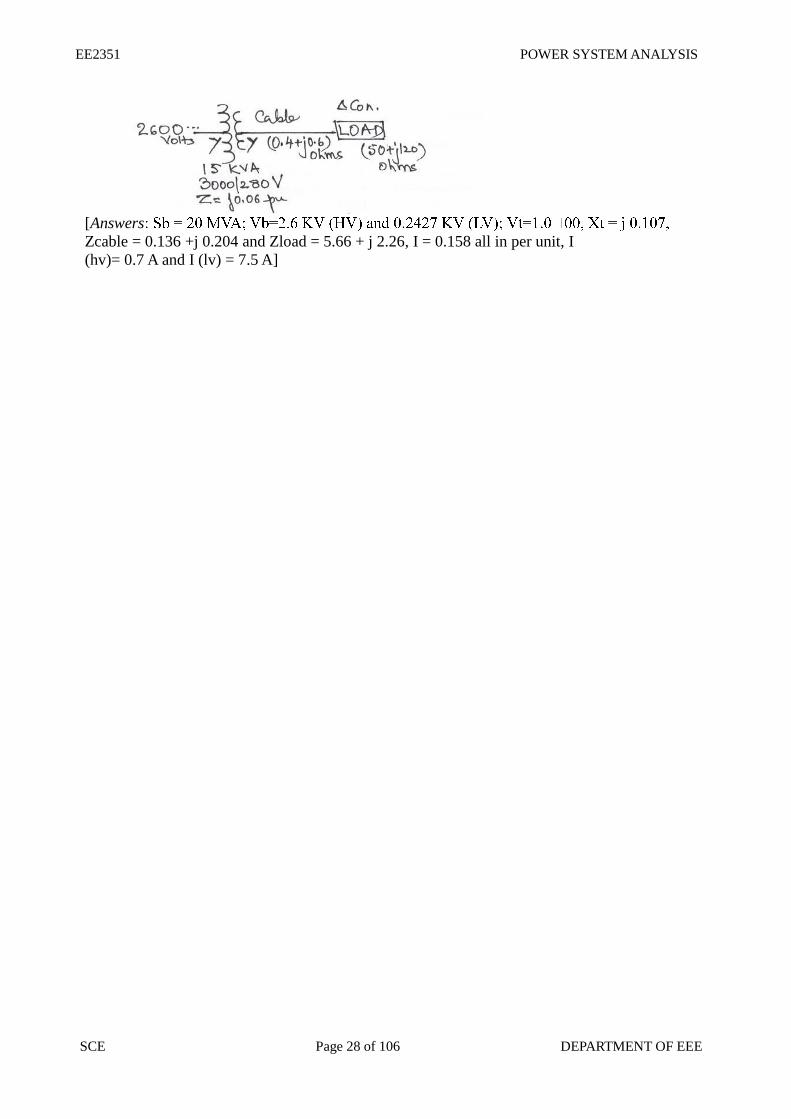
4. For the three-phase system shown below, draw an impedance diagram expressing all
impedances in per unit on a common base of 20 MVA, 2600 V on the HV side of the transformer.
Using this impedance diagram, find the HV and LV currents.
EE2351 POWER SYSTEM ANALYSIS
SCE Page 28 of 106 DEPARTMENT OF EEE
[Answers
Zcable = 0.136 +j 0.204 and Zload = 5.66 + j 2.26, I = 0.158 all in per unit, I
(hv)= 0.7 A and I (lv) = 7.5 A]
EE2351 POWER SYSTEM ANALYSIS
SCE Page 29 of 106 DEPARTMENT OF EEE
UNIT II POWER FLOW ANALYSIS
2.1. IMPORTANCE OF POWER FLOW ANALYSIS IN PLANNING AND OPERATION
OF POWER SYSTEMS.
POWER FLOW STUDY OR LOAD FLOW STUDY The study of various methods of solution to power system network is referred to as load flow study.
The solution provides the voltages at various buses, power flowing in various lines and line losses.
Information’s that are obtained from a load flow study The information obtained from a load flow study is magnitude and phase angle of voltages, real and
reactive power flowing in each line and the line losses. The load flow solution also gives the initial
conditions of the system when the transient behavior of the system is to be studied.
Need for load flow study The load flow study of a power system is essential to decide the best operation of existing system and
for planning the future expansion of the system. It is also essential for designing a new power
system.
2.2. STATEMENT OF POWER FLOW PROBLEM
Quantities associated with each bus in a system Each bus in a power system is associated with four quantities and they are real power (P), reactive
power (Q), magnitude of voltage (V), and phase angle of voltage (δ).
Work involved (or) to be performed by a load flow study
(i). Representation of the system by a single line diagram
(ii). Determining the impedance diagram using the information in single line diagram
(iii). Formulation of network equation
(iv). Solution of network equations
Iterative methods to solve load flow problems
The load flow equations are non linear algebraic equations and so explicit solution as not possible.
The solution of non linear equations can be obtained only by iterative numerical techniques.
Mainly used for solution of load flow study The Gauss seidal method, Newton Raphson method and Fast decouple methods.
Flat voltage start
In iterative method of load flow solution, the initial voltages of all buses except slack bus assumed as
1+j0 p.u. This is referred to as flat voltage start
2.3. CLASSIFICATION OF BUSES
Bus The meeting point of various components in a power system is called a bus. The bus is a conductor
made of copper or aluminum having negligible resistance .At some of the buses power is being
injected into the network, whereas at other buses it is being tapped by the system lods.
Bus admittance matrix The matrix consisting of the self and mutual admittance of the network of the power system is called
bus admittance matrix (Ybus).
Methods available for forming bus admittance matrix Direct inspection method.
The slack bus is needed to account for transmission line losses. In a power system the total power
generated will be equal to sum of power consumed by loads and losses. In a power system only the
generated power and load power are specified for buses. The slack bus is assumed to generate the
power required for losses. Since the losses are unknown the real and reactive power are not specified
for slack bus.
Effect of acceleration factor in load flow study Acceleration factor is used in gauss seidal method of load flow solution to increase the rate of
convergence. Best value of A.F=1.6
Generator buses are treated as load bus If the reactive power constraint of a generator bus violates the specified limits then the generator is
treated as load bus.
2.4. ITERATIVE SOLUTION USING GAUSS-SEIDEL METHOD - ALGORITHM
Algorithm of Gauss seidal method
Step1: Assume all bus voltage be 1+ j0 except slack bus. The voltage of the slack bus is a
constant voltage and it is not modified at any iteration
Step 2: Assume a suitable value for specified change in bus voltage which is used to
compare the actual change in bus voltage between K th
and (K+1) th
iteration
Step 3: Set iteration count K = 0 and the corresponding voltages are V10, V2
0, V3
0, ……
Vn0 except slack bus
Step 4: Set bus count P = 1
Step 5: Check for slack bus. It is a slack bus then goes to step 12 otherwise go to next
step
Step 6: Check for generator bus. If it is a generator bus go to next step. Otherwise go to
step 9
Step 7: Set VPK= VP specified and phase of VP
K as the K
th iteration value if the
bus P is a generator bus where VP specified is the specified magnitude of
voltage for bus P. Calculate reactive power rating
P-1 n
QP K+1
Cal = (-1) Imag [(VPK)
A (∑ Y pq Vq
k+1 +∑ Y pq Vq
K
q=1 q =P
Step 8: If calculated reactive power is within the specified limits then consider the bus as
generator bus and then set QP = QP K+1
Cal for this iteration go to step 10
Step 9 : If the calculated reactive power violates the specified limit for reactive power
then treat this bus as load bus
If QP K+1
Cal < QP min then QP = QP min
QP K+1
Cal > QP max then QP = QP max
Step10: For generator bus the magnitude of voltage does not change and so for all
iterations the magnitude of bus voltage is the specified value. The phase of the
bus voltage can be calculated using
EE2351 POWER SYSTEM ANALYSIS
SCE Page 31 of 106 DEPARTMENT OF EEE
VPK+1
temp = 1 / YPP [(PP –jQP / VPK *) - ∑YpqVq
K+1 - ∑YpqVq
K]
Step 11: For load bus the (k+1)th iteration value of load bus P voltage VPK+1 can be
calculated using VPK+1
temp = 1 / YPP [(PP –jQP / VPK *) - ∑YpqVq
K+1 - ∑YpqVq
K]
Step 12: An acceleration factor α can be used for faster convergence. If acceleration
factor is specified then modify the (K+1)th
iteration value of bus P using
VPaccK+1
= VPK + α (VP
K+1 – VP
K) then
Set VPK+1
= VPaccK+1
Step 13: Calculate the change in bus-P voltage using the relation Δ VPK+1
= VPK+1
-VPK
Step 14: Repeat step 5 to 12 until all the bus voltages have been calculated. For this
increment the bus count by 1 go to step 5 until the bus count is n
Step 15: Find the largest of the absolute value of the change in voltage
ΔV1K+1
,ΔV2K+1
,ΔV3K+1
, ……………ΔVnK+1
Let this largest value be the ΔVmax. Check this largest change ΔVmax is less than
pre specified tolerance. If ΔVmax is less go to next step. Otherwise increment the iteration
count and go to step 4
Step 16: Calculate the line flows and slack bus power by using the bus voltages
Gauss - Seidal method flow chart
EE2351 POWER SYSTEM ANALYSIS
SCE Page 32 of 106 DEPARTMENT OF EEE
EE2351 POWER SYSTEM ANALYSIS
SCE Page 33 of 106 DEPARTMENT OF EEE
EE2351 POWER SYSTEM ANALYSIS
SCE Page 34 of 106 DEPARTMENT OF EEE
.
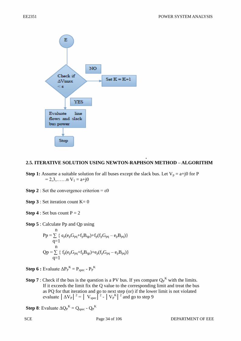
2.5. ITERATIVE SOLUTION USING NEWTON-RAPHSON METHOD – ALGORITHM
Step 1: Assume a suitable solution for all buses except the slack bus. Let Vp = a+j0 for P
= 2,3,……n V1 = a+j0
Step 2 : Set the convergence criterion = ε0
Step 3 : Set iteration count K= 0
Step 4 : Set bus count P = 2
Step 5 : Calculate Pp and Qp using
n
Pp = ∑ ep(epGpq+fpBqp)+fp(fpGpq – epBpq)
q=1
n
Qp = ∑ fp(epGpq+fpBqp)+ep(fpGpq – epBpq)
q=1
Step 6 : Evaluate ΔPPK = Pspec - PP
K
Step 7 : Check if the bus is the question is a PV bus. If yes compare QPK with the limits.
If it exceeds the limit fix the Q value to the corresponding limit and treat the bus
as PQ for that iteration and go to next step (or) if the lower limit is not violated
evaluate ΔVP2 = Vspec
2 - VP
K
2 and go to step 9
Step 8: Evaluate ΔQPK = Qspec - QP
K
EE2351 POWER SYSTEM ANALYSIS
SCE Page 35 of 106 DEPARTMENT OF EEE
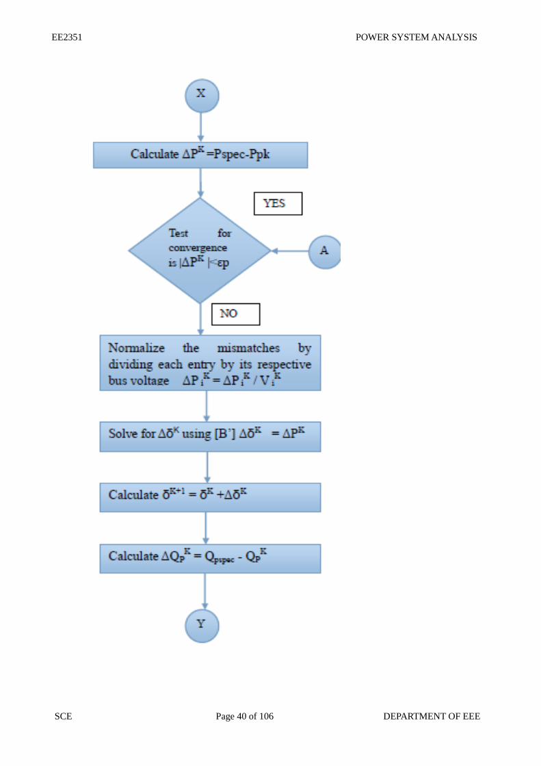
Step 9 : Advance bus count P = P+1 and check if all buses taken in to account if not go to
step 5
Step 10 : Determine the largest value of ΔVP2
Step 11: If ΔVP < ε go to step 16
Step 12: Evaluate the element of Jacobin matrices J1, J2, J3, J4, J5 and J6
Step 13: Calculate ΔePK and ΔfP
K
Step 14: Calculate ePK+1
= ePK
+ ΔePK and fP
K+1 = fP
K + ΔfP
K
Step 15 : Advance count (iteration) K=K+1 and go to step 4
Step 16: Evaluate bus and line power and print the result
Iterative solution using Newton-Raphson method – Flow chart
EE2351 POWER SYSTEM ANALYSIS
SCE Page 36 of 106 DEPARTMENT OF EEE
EE2351 POWER SYSTEM ANALYSIS
SCE Page 37 of 106 DEPARTMENT OF EEE
2.6. ITERATIVE SOLUTION USING FAST DECOUPLED LOAD FLOW METHOD –
ALGORITHM Step 1: Assume a suitable solution for all buses except the slack bus. Let Vp =1+j0 for
P=2,3,...................n and V=a+j0
Step2: Set the convergence criterion = ε0
EE2351 POWER SYSTEM ANALYSIS
SCE Page 38 of 106 DEPARTMENT OF EEE
Step3: Set iteration count K = 0
Step 4: Set bus count P = 2
Step 5: Calculate Pp and Qp using
n
Pp = Σ |VpVqYpq| cos (θpq+δP-δq)
q=1 Qp = Σ |VpVqYpq| sin (θpq+δP-δq)
q=1
Step 6: Compute the real and reactive power mismatches ΔPK
and ΔQK. If the mismatches
Are with in desirable tolerance the iteration end
Step 7: Normalize the mismatches by dividing each entry by its respective bus voltage
magnitude ΔPK
=ΔP 2K / V 2
K
ΔP 3
K / V 3
K
. . ΔP n
K / V n
K
ΔQ
K =ΔQ 2
K / V 2
K
ΔQ 3
K / V 3
K
. . ΔQ n
K / V n
K
Step 8: Solve for the voltage magnitude and the correction factors ΔVK
and ΔδK by using the
constant matrices B’ and B” which are extracted from the bus admittance matrix Y Bus
[B’] ΔδK = ΔP
K
[B”]ΔQK
= ΔQK
Step 9: Up date the voltage magnitude and angel vectors
δK+1 = δK
+ΔδK
VK+1
= VK +ΔV
K
Step 10: Check if all the buses are taken into account if yes go to next step otherwise go
to next step. Otherwise go to step 4
Step 11: Advance iteration count K = K+1 go to step 3
Step 12: Evaluate bus and load powers and print the results
EE2351 POWER SYSTEM ANALYSIS
SCE Page 39 of 106 DEPARTMENT OF EEE
EE2351 POWER SYSTEM ANALYSIS
SCE Page 40 of 106 DEPARTMENT OF EEE
EE2351 POWER SYSTEM ANALYSIS
SCE Page 41 of 106 DEPARTMENT OF EEE
2.7 ITERATIVE SOLUTION USING FAST DECOUPLED LOAD FLOW METHOD –
FLOW CHART
Advantages and disadvantages of Gauss-Seidel method
Advantages: Calculations are simple and so the programming task is lessees. The memory
requirement is less. Useful for small systems;
Disadvantages: Requires large no. of iterations to reach converge .Not suitable for large
systems. Convergence time increases with size of the system
Advantages and disadvantages of N.R method
EE2351 POWER SYSTEM ANALYSIS
SCE Page 42 of 106 DEPARTMENT OF EEE
Advantages: Faster, more reliable and results are accurate, require less number of iterations;
Disadvantages: Program is more complex, memory is more complex.
2.8 COMPARE THE GAUSS SEIDEL AND NEWTON RAPHSON METHODS OF LOAD
FLOW STUDY
S.No G.S N.R FDLF
1 Require large
number of iterations
to reach
convergence
Require less number
of iterations to reach
convergence.
Require more
number of iterations
than N.R method
2 Computation time
per iteration is less Computation time
per iteration is more Computation time
per iteration is less
3 It has linear
convergence
characteristics
It has quadratic
convergence
characteristics
….
4 The number of
iterations required
for convergence
increases with size
of the system
The number of
iterations are
independent of the
size of the system
The number of
iterations are does
not dependent of the
size of the system
5 Less memory
requirements More memory
requirements.
Less memory
requirements than
N.R.method.
Y matrix of the sample power system as shown in fig. Data for this system is given in table.
. .
EE2351 POWER SYSTEM ANALYSIS
SCE Page 43 of 106 DEPARTMENT OF EEE
UNIT III FAULT ANALYSIS – BALANCED FAULTS
3.1. IMPORTANCE SHORT CIRCUIT (OR) FOR FAULT ANALYSIS
Fault A fault in a circuit is any failure which interferes with the normal flow of current. The faults are
associated with abnormal change in current, voltage and frequency of the power system.
Faults occur in a power system The faults occur in a power system due to (i). Insulation failure of equipment
(ii). Flashover of lines initiated by a lighting stroke
(iii). Due to permanent damage to conductors and towers or due to accidental faulty operations.
Various types of faults (i) Series fault or open circuit fault
One open conductor fault
Two open conductor fault
(ii) Shunt fault or short circuit fault.
Symmetrical fault or balanced fault
Three phase fault
Unsymmetrical fault or unbalanced fault Line to ground (L-G) fault
Line to Line (L-L) fault
Double line to ground (L-L-G) fault
Relative frequency of occurrence of various types of fault
Types of fault Relative frequency of occurrence of
faults
Three phase fault 5%
Double line to ground fault 10%
Line to Line fault 15%
Line to ground fault 70%
Symmetrical fault or balanced three phase fault This type of fault is defined as the simultaneous short circuit across all the three phases. It occurs
infrequently, but it is the most severe type of fault encountered. Because the network is balanced, it is
solved by per phase basis using Thevenins theorem or bus impedance matrix or KVL, KCL laws.
3.2. BASIC ASSUMPTIONS IN FAULT ANALYSIS OF POWER SYSTEMS. (i). Representing each machine by a constant voltage source behind proper reactance which may be
X”, X’, or X
(ii). Pre-fault load current are neglected
(iii). Transformer taps are assumed to be nominal
(iv). Shunt elements in the transformers model that account for magnetizing current and core loss are
neglected
(v). A symmetric three phase power system is conducted
(vi). Shunt capacitance and series resistance in transmission are neglected
EE2351 POWER SYSTEM ANALYSIS
SCE Page 44 of 106 DEPARTMENT OF EEE
(vii). The negative sequence impedances of alternators are assumed to be the same as their positive
sequence impedance Z+ = Z-
Need for short circuit studies or fault analysis Short circuit studies are essential in order to design or develop the protective schemes for various
parts of the system .To estimate the magnitude of fault current for the proper choice of circuit breaker
and protective relays.
Bolted fault or solid fault
A Fault represents a structural network change equivalent with that caused by the addition of
impedance at the place of a fault. If the fault impedance is zero, the fault is referred as bolted fault or
solid fault.
Reason for transients during short circuits The faults or short circuits are associated with sudden change in currents. Most of the components of
the power system have inductive property which opposes any sudden change in currents, so the faults
are associated with transients.
Doubling effect If a symmetrical fault occurs when the voltage wave is going through zero then the maximum
momentary short circuit current will be double the value of maximum symmetrical short circuit
current. This effect is called doubling effect.
DC off set current The unidirectional transient component of short circuit current is called DC off set current.
3.3. SYMMETRICAL FAULT
In symmetrical faults all the three phases are short circuited to each other and to earth also. Such
faults are balanced and symmetrical in the sense that the voltage and current of the system
remains balanced even after the fault and it is enough if we consider any one phase
Short circuit capacity of power system or fault level. Short circuit capacity (SCC) or Short circuit MVA or fault level at a bus is defined as the product of
the magnitude of the pre fault bus voltage and the post fault current
(OR)
Synchronous reactance or steady state condition reactance The synchronous reactance is the ratio of induced emf and the steady state rms current. It is the sum
of leakage reactance (Xl) and the armature reactance (Xa).
EE2351 POWER SYSTEM ANALYSIS
SCE Page 45 of 106 DEPARTMENT OF EEE
Sub transient reactance
The synchronous reactance is the ratio of induced emf on no load and the sub transient symmetrical
rms current.
Transient reactance The synchronous reactance is the ratio of induced emf on no load and the transient symmetrical rms
current.
Fault current in fig., if the Pre-fault voltage at the fault point is 0.97 p.u.
EE2351 POWER SYSTEM ANALYSIS
SCE Page 46 of 106 DEPARTMENT OF EEE
Thevenin’s theorem:
(i). Fault current = Eth / (Zth+Zf)
(ii). Determine current contributed by the two generators IG1 = If * (Z2/(Z1+Z2))
IG2 = If * (Z1 / (Z1+Z2))
(iii). Determine Post fault voltage Vif = Vi°+ΔV = V°+(-Zi2*IGi)
(iv). Determine post fault voltage line flows Iij = (Vi –Vj) / Zij series
(v). Short circuit capacity If = Eth2 / Xth
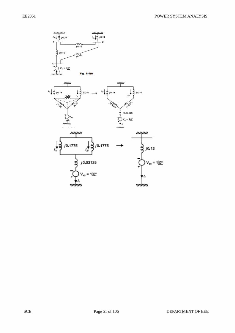
3.4. FAULT ANALYSIS USING Z-BUS MATRIX – ALGORITHM AND FLOW CHART.
Bus impedance matrix Bus impedance matrix is the inverse of the bus admittance matrix. The matrix consisting of driving
point impedance and transfer impedances of the network is called as bus impedance matrix. Bus
impedance matrix is symmetrical.
Methods available for forming bus impedance matrix (i). Form bus admittance matrix and take the inverse to get bus impedance matrix.
(ii). Using bus building algorithm.
(iii). Using L-U factorization of Y-bus matrix.
3.5 SOLVED PROBLEMS
Problem 1
A synchronous generator and a synchronous motor each rated 20MVA, 12.66KV having 15%
reactance are connected through transformers and a line as shown in fig. the transformers are rated
20MVA,12.66/66KV and 66/12.66KV with leakage reactance of 10% each. The line has a reactance
of 8% on base of 20MVA, 66 KV. The motor is drawing 10MW at 0.8 leading power factors and a
terminal voltage 11KV when symmetrical three phase fault occurs at the motors terminals. Determine
the generator and motor currents. Also determine the fault current.
EE2351 POWER SYSTEM ANALYSIS
SCE Page 47 of 106 DEPARTMENT OF EEE
EE2351 POWER SYSTEM ANALYSIS
SCE Page 48 of 106 DEPARTMENT OF EEE
EE2351 POWER SYSTEM ANALYSIS
SCE Page 49 of 106 DEPARTMENT OF EEE
EE2351 POWER SYSTEM ANALYSIS
SCE Page 50 of 106 DEPARTMENT OF EEE
EE2351 POWER SYSTEM ANALYSIS
SCE Page 51 of 106 DEPARTMENT OF EEE
EE2351 POWER SYSTEM ANALYSIS
SCE Page 52 of 106 DEPARTMENT OF EEE
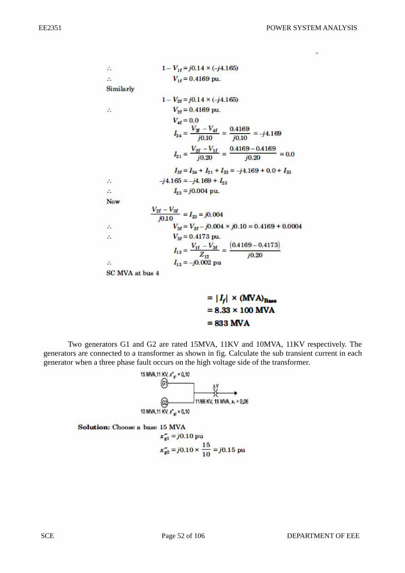
Two generators G1 and G2 are rated 15MVA, 11KV and 10MVA, 11KV respectively. The
generators are connected to a transformer as shown in fig. Calculate the sub transient current in each
generator when a three phase fault occurs on the high voltage side of the transformer.
EE2351 POWER SYSTEM ANALYSIS
SCE Page 53 of 106 DEPARTMENT OF EEE
A radial power system network is shown in fig. a three phase balanced fault occurs at F.
Determine the fault current and the line voltage at 11.8 KV bus under fault condition.
EE2351 POWER SYSTEM ANALYSIS
SCE Page 54 of 106 DEPARTMENT OF EEE
EE2351 POWER SYSTEM ANALYSIS
SCE Page 55 of 106 DEPARTMENT OF EEE
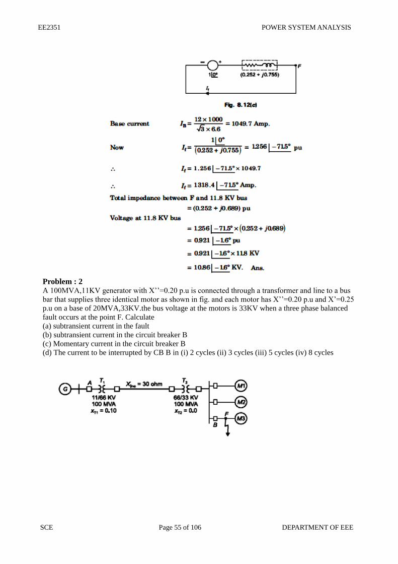
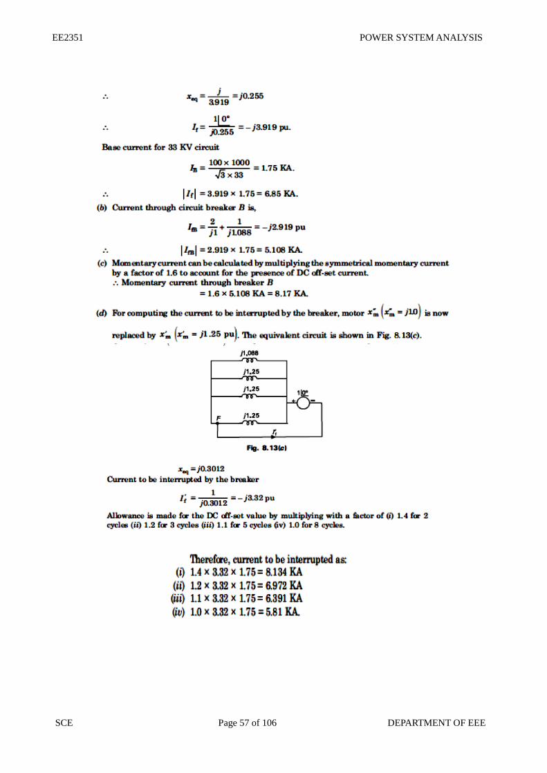
Problem : 2 A 100MVA,11KV generator with X’’=0.20 p.u is connected through a transformer and line to a bus
bar that supplies three identical motor as shown in fig. and each motor has X’’=0.20 p.u and X’=0.25
p.u on a base of 20MVA,33KV.the bus voltage at the motors is 33KV when a three phase balanced
fault occurs at the point F. Calculate
(a) subtransient current in the fault
(b) subtransient current in the circuit breaker B
(c) Momentary current in the circuit breaker B
(d) The current to be interrupted by CB B in (i) 2 cycles (ii) 3 cycles (iii) 5 cycles (iv) 8 cycles
EE2351 POWER SYSTEM ANALYSIS
SCE Page 56 of 106 DEPARTMENT OF EEE
EE2351 POWER SYSTEM ANALYSIS
SCE Page 57 of 106 DEPARTMENT OF EEE
EE2351 POWER SYSTEM ANALYSIS
SCE Page 58 of 106 DEPARTMENT OF EEE
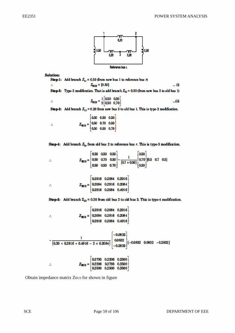
Obtain impedance matrix ZBUS for shown in figure.
EE2351 POWER SYSTEM ANALYSIS
SCE Page 59 of 106 DEPARTMENT OF EEE
Obtain impedance matrix ZBUS for shown in figure
EE2351 POWER SYSTEM ANALYSIS
SCE Page 60 of 106 DEPARTMENT OF EEE
EE2351 POWER SYSTEM ANALYSIS
SCE Page 61 of 106 DEPARTMENT OF EEE
UNIT- IV
SYMMETRICAL COMPONENTS AND UNBALANCED FAULT ANALYSIS
4.1. INTRODUCTION TO SYMMETRICAL COMPONENTS
Symmetrical components of a 3 phase system In a 3 phase system, the unbalanced vectors (either currents or voltage) can be resolved into three
balanced system of vectors.
They are Positive sequence components
Negative sequence components
Zero sequence components
Unsymmetrical fault analysis can be done by using symmetrical components.
Positive sequence components It consists of three components of equal magnitude, displaced each other by 120˚ in phase and having
the phase sequence abc .
Negative sequence components It consists of three components of equal magnitude, displaced each other by 120˚ in phase and having
the phase sequence acb .
Zero sequence components It consists of three phasors equal in magnitude and with zero phase displacement from each other.
EE2351 POWER SYSTEM ANALYSIS
SCE Page 62 of 106 DEPARTMENT OF EEE
Sequence operator In unbalanced problem, to find the relationship between phase voltages and phase currents, we use
sequence operator ‘a’.
a = 1∠120˚ == - 0.5+j0.866
Unbalanced currents from symmetrical currents Let, Ia, Ib, Ic be the unbalanced phase currents
Let, Ia0, Ia1, Ia2 be the symmetrical components of phase a
Determination of symmetrical currents from unbalanced currents. Let, Ia, Ib, Ic be the unbalanced phase currents
Let, Ia0, Ia1, Ia2 be the symmetrical components of phase a
4.2. SEQUENCE IMPEDANCES SEQUENCE NETWORKS The sequence impedances are the impedances offered by the power system components or elements
to +ve, -ve and zero sequence current.
The single phase equivalent circuit of power system consisting of impedances to current of any one
sequence only is called sequence network.
The phase voltage across a certain load are given as
EE2351 POWER SYSTEM ANALYSIS
SCE Page 63 of 106 DEPARTMENT OF EEE
Compute positive, negative and zero sequence component of voltage
A balanced delta connected load is connected to a three phase system and supplied to it is a current of
15 amps. If the fuse is one of the lines melts, compute the symmetrical components of line currents.
Draw zero sequence network of the power system as shown in fig.
EE2351 POWER SYSTEM ANALYSIS
SCE Page 64 of 106 DEPARTMENT OF EEE
Draw zero sequence network of the power system as shown in fig.
Draw zero sequence network of the power system as shown in fig. Data are given below.
EE2351 POWER SYSTEM ANALYSIS
SCE Page 65 of 106 DEPARTMENT OF EEE
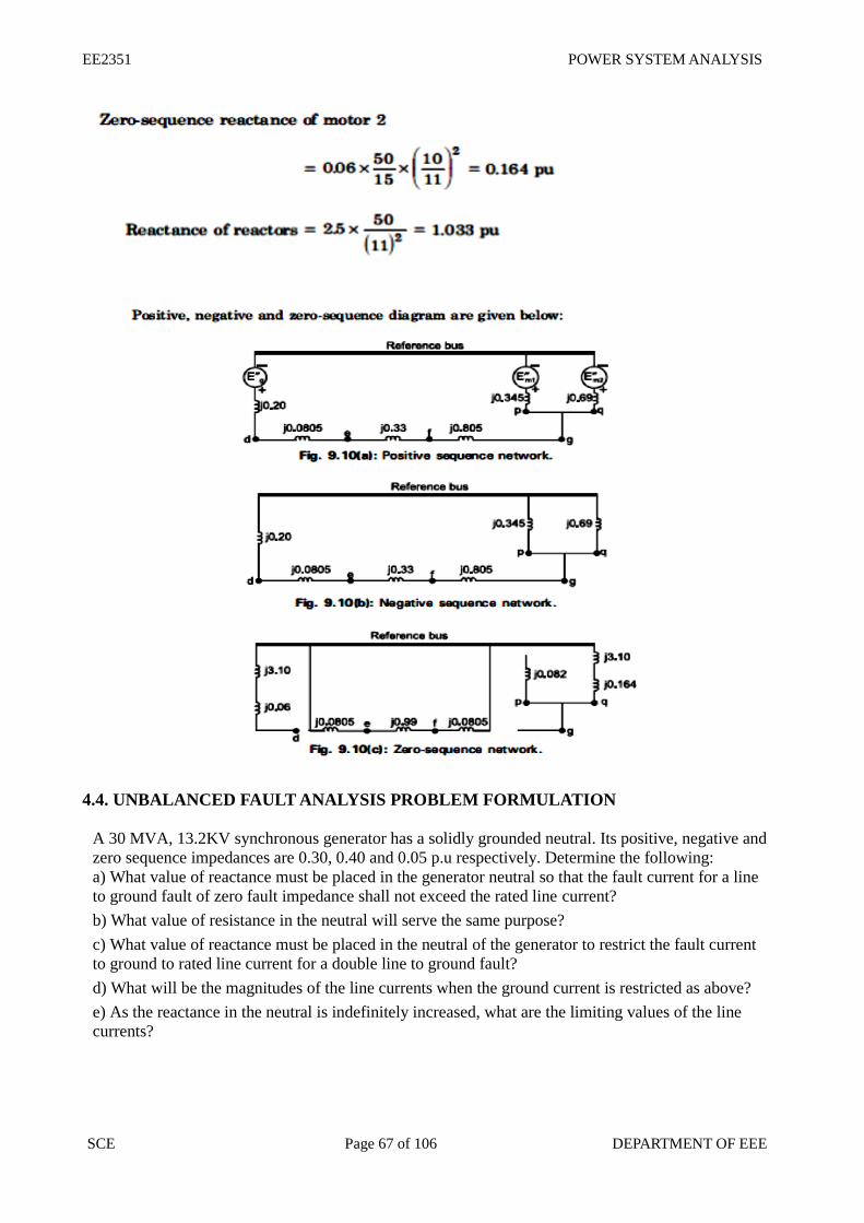
4.3. REPRESENTATION OF SINGLE LINE TO GROUND, LINE TO LINE AND
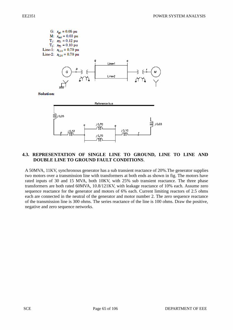
DOUBLE LINE TO GROUND FAULT CONDITIONS.
A 50MVA, 11KV, synchronous generator has a sub transient reactance of 20%.The generator supplies
two motors over a transmission line with transformers at both ends as shown in fig. The motors have
rated inputs of 30 and 15 MVA, both 10KV, with 25% sub transient reactance. The three phase
transformers are both rated 60MVA, 10.8/121KV, with leakage reactance of 10% each. Assume zero
sequence reactance for the generator and motors of 6% each. Current limiting reactors of 2.5 ohms
each are connected in the neutral of the generator and motor number 2. The zero sequence reactance
of the transmission line is 300 ohms. The series reactance of the line is 100 ohms. Draw the positive,
negative and zero sequence networks.
EE2351 POWER SYSTEM ANALYSIS
SCE Page 66 of 106 DEPARTMENT OF EEE
EE2351 POWER SYSTEM ANALYSIS
SCE Page 67 of 106 DEPARTMENT OF EEE
4.4. UNBALANCED FAULT ANALYSIS PROBLEM FORMULATION
A 30 MVA, 13.2KV synchronous generator has a solidly grounded neutral. Its positive, negative and
zero sequence impedances are 0.30, 0.40 and 0.05 p.u respectively. Determine the following:
a) What value of reactance must be placed in the generator neutral so that the fault current for a line
to ground fault of zero fault impedance shall not exceed the rated line current?
b) What value of resistance in the neutral will serve the same purpose?
c) What value of reactance must be placed in the neutral of the generator to restrict the fault current
to ground to rated line current for a double line to ground fault?
d) What will be the magnitudes of the line currents when the ground current is restricted as above?
e) As the reactance in the neutral is indefinitely increased, what are the limiting values of the line
currents?
EE2351 POWER SYSTEM ANALYSIS
SCE Page 68 of 106 DEPARTMENT OF EEE
EE2351 POWER SYSTEM ANALYSIS
SCE Page 69 of 106 DEPARTMENT OF EEE
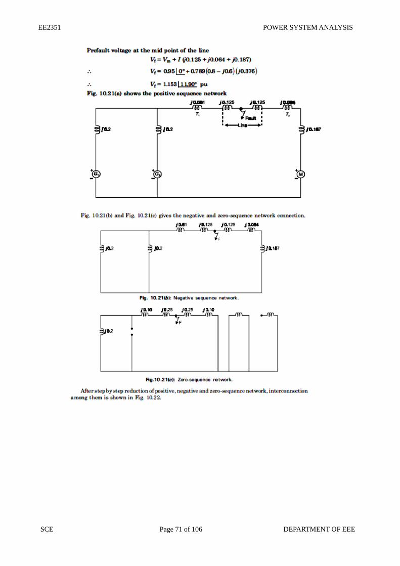
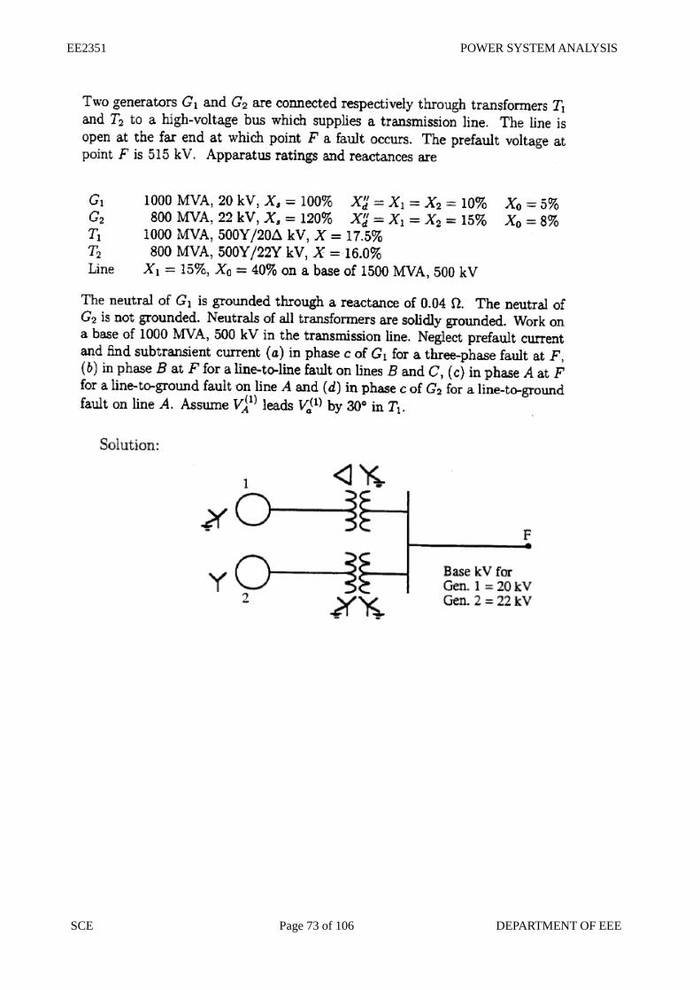
Two alternators are operating in parallel and supplying a synchronous motor which is receiving
60MW power at 0.8 power factor lagging at 6.0 KV. Single line diagram for this system is given in
fig. Data are given below. Compute the fault current when a single line to ground fault occurs at the
middle of the line through a fault resistance of 4.033 ohm.
EE2351 POWER SYSTEM ANALYSIS
SCE Page 70 of 106 DEPARTMENT OF EEE
EE2351 POWER SYSTEM ANALYSIS
SCE Page 71 of 106 DEPARTMENT OF EEE
EE2351 POWER SYSTEM ANALYSIS
SCE Page 72 of 106 DEPARTMENT OF EEE
EE2351 POWER SYSTEM ANALYSIS
SCE Page 73 of 106 DEPARTMENT OF EEE
EE2351 POWER SYSTEM ANALYSIS
SCE Page 74 of 106 DEPARTMENT OF EEE
EE2351 POWER SYSTEM ANALYSIS
SCE Page 75 of 106 DEPARTMENT OF EEE
EE2351 POWER SYSTEM ANALYSIS
SCE Page 76 of 106 DEPARTMENT OF EEE
UNIT V STABILITY ANALYSIS
5.1. IMPORTANCE OF STABILITY ANALYSIS IN POWER SYSTEM PLANNING AND
OPERATION
Power system stability The stability of an interconnected power system means is the ability of the power system is to return
or regain to normal or stable operating condition after having been subjected to some form of
disturbance.
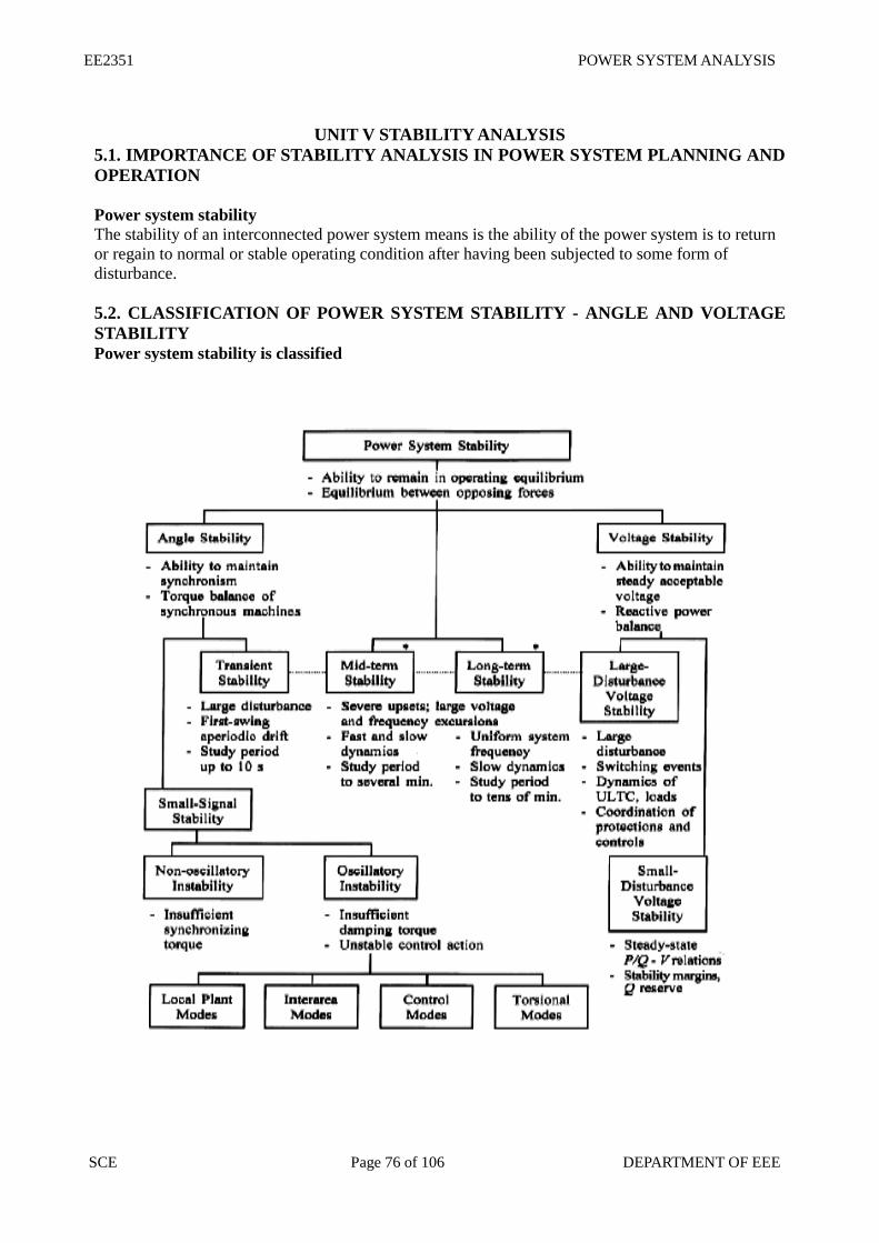
5.2. CLASSIFICATION OF POWER SYSTEM STABILITY - ANGLE AND VOLTAGE
STABILITY
Power system stability is classified
EE2351 POWER SYSTEM ANALYSIS
SCE Page 77 of 106 DEPARTMENT OF EEE
5.3 ANGLE AND VOLTAGE STABILITY
Rotor angle stability Rotor angle stability is the ability of interconnected synchronous machines of a power system to
remain in synchronism.
Steady state stability Steady state stability is defined as the ability of the power system to bring it to a stable condition or
remain in synchronism after a small disturbance.
Steady state stability limit The steady sate stability limit is the maximum power that can be transferred by a machine to
receiving system without loss of synchronism
Transient stability
Transient stability is defined as the ability of the power system to bring it to a stable condition or
remain in synchronism after a large disturbance.
Transient stability limit The transient stability limit is the maximum power that can be transferred by a machine to a fault or a
receiving system during a transient state without loss of synchronism.Transient stability limit is
always less than steady state stability limit
Dynamic stability It is the ability of a power system to remain in synchronism after the initial swing (transient stability
period) until the system has settled down to the new steady state equilibrium condition
Voltage stability It is the ability of a power system to maintain steady acceptable voltages at all buses in the system
under normal operating conditions and after being subjected to a disturbance.
Causes of voltage instability A system enters a state of voltage instability when a disturbance, increase in load demand, or change
in system condition causes a progressive and uncontrollable drop in voltage. The main factor causing
instability is the inability of the power system to meet the demand for reactive power.
Determination of critical clearing angle and time
Power angle equation and draw the power angle curve
Where, P – Real Power in watts
Vs – Sending end voltage; Vr- Receiving end voltage
XT - Total reactance between sending end receiving end
δ- Rotor angle.
EE2351 POWER SYSTEM ANALYSIS
SCE Page 78 of 106 DEPARTMENT OF EEE
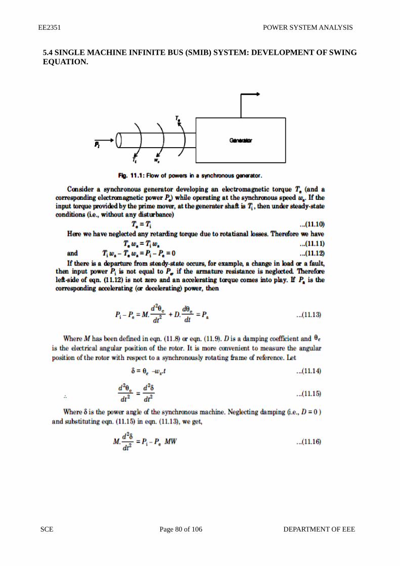
Swing equation for a SMIB (Single machine connected to an infinite bus bar) system.
Where H = inertia constant in MW/MVA
f = frequency in Hz
M = inertia constant in p.u
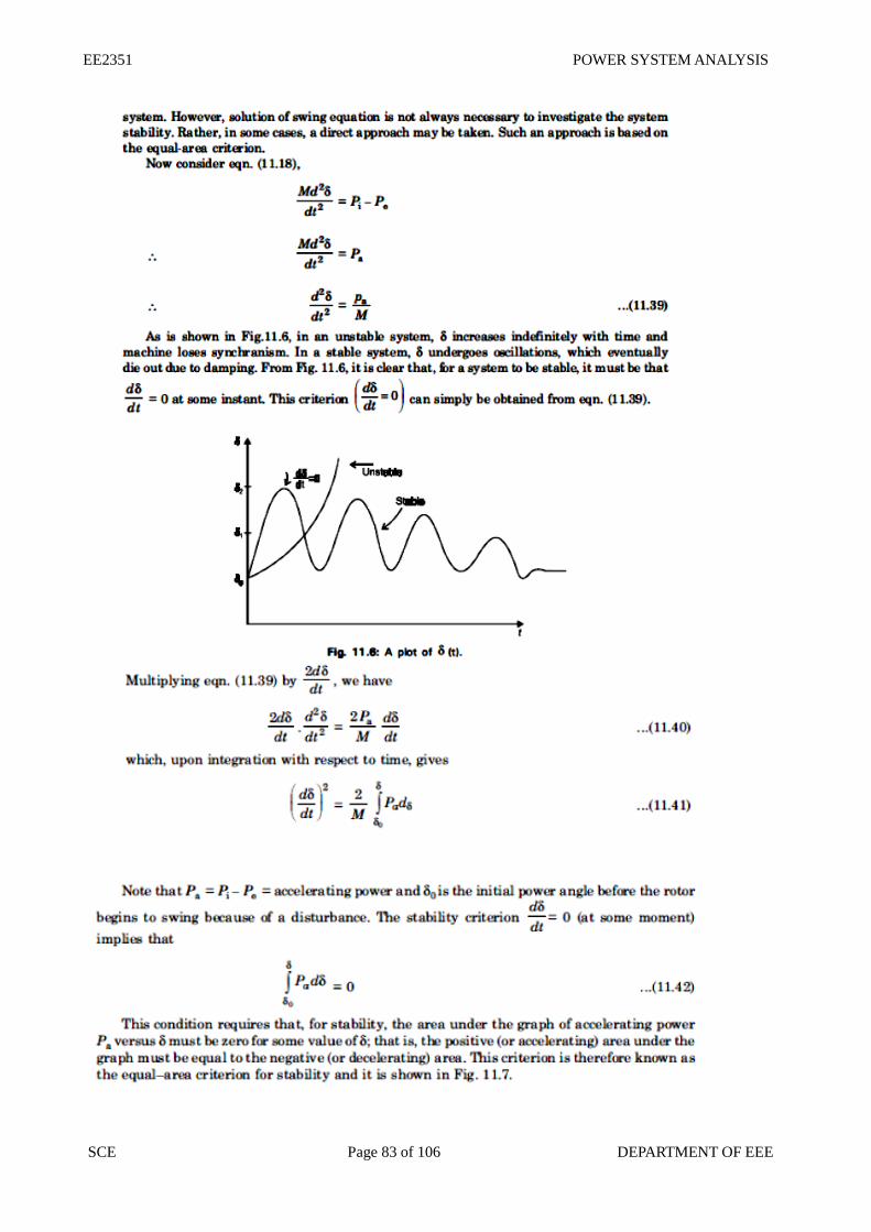
Swing curve The swing curve is the plot or graph between the power angle δ and time t. From the nature of
variations of δ the stability of a system for any disturbance can be determined.
3 machine system having ratings G1, G2 and G3 and inertia constants M1, M2 and M3.What is
the inertia constants M and H of the equivalent system.
EE2351 POWER SYSTEM ANALYSIS
SCE Page 79 of 106 DEPARTMENT OF EEE
Where G1, G2, G3 – MVA rating of machines 1, 2, and 3
Gb = Base MVA or system MVA
Assumptions made in stability studies. (i). Machines represents by classical model
(ii). The losses in the system are neglected (all resistance are neglected)
(iii). The voltage behind transient reactance is assumed to remain constant.
(iv). Controllers are not considered ( Shunt and series capacitor )
(v). Effect of damper winding is neglected.
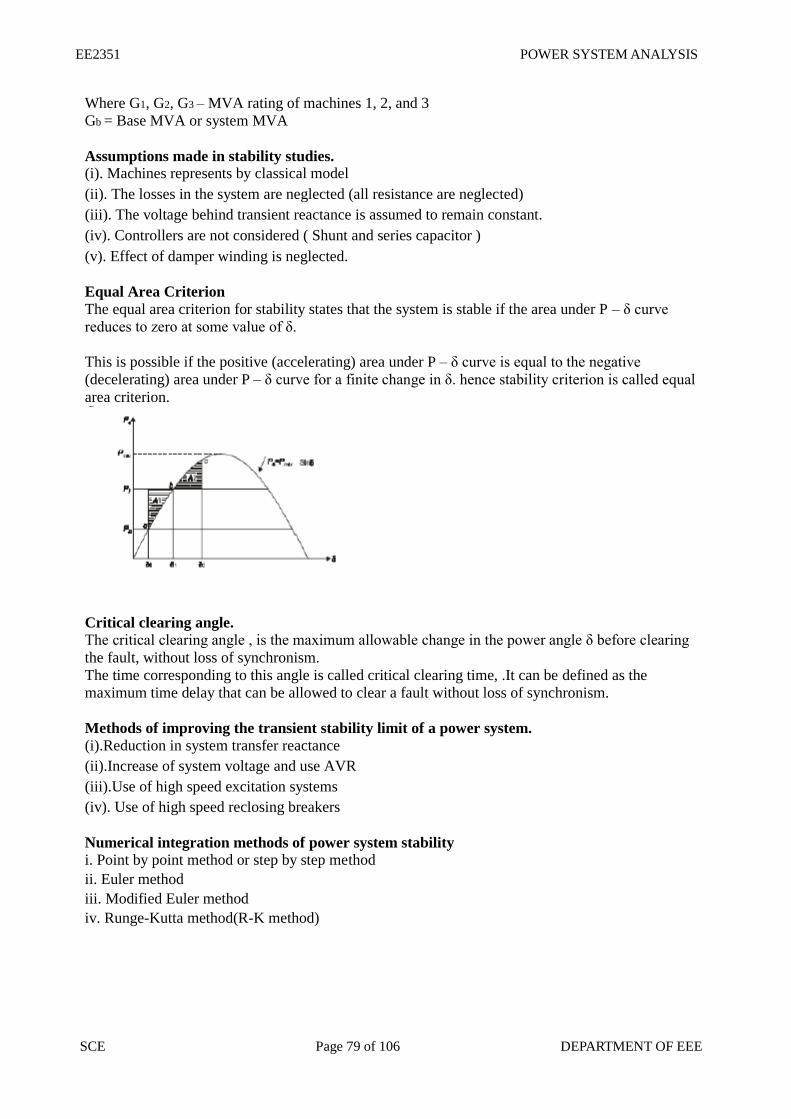
Equal Area Criterion The equal area criterion for stability states that the system is stable if the area under P – δ curve
reduces to zero at some value of δ.
This is possible if the positive (accelerating) area under P – δ curve is equal to the negative
(decelerating) area under P – δ curve for a finite change in δ. hence stability criterion is called equal
area criterion.
Critical clearing angle. The critical clearing angle , is the maximum allowable change in the power angle δ before clearing
the fault, without loss of synchronism.
The time corresponding to this angle is called critical clearing time, .It can be defined as the
maximum time delay that can be allowed to clear a fault without loss of synchronism.
Methods of improving the transient stability limit of a power system. (i).Reduction in system transfer reactance
(ii).Increase of system voltage and use AVR
(iii).Use of high speed excitation systems
(iv). Use of high speed reclosing breakers
Numerical integration methods of power system stability i. Point by point method or step by step method
ii. Euler method
iii. Modified Euler method
iv. Runge-Kutta method(R-K method)
EE2351 POWER SYSTEM ANALYSIS
SCE Page 80 of 106 DEPARTMENT OF EEE
5.4 SINGLE MACHINE INFINITE BUS (SMIB) SYSTEM: DEVELOPMENT OF SWING
EQUATION.
EE2351 POWER SYSTEM ANALYSIS
SCE Page 81 of 106 DEPARTMENT OF EEE
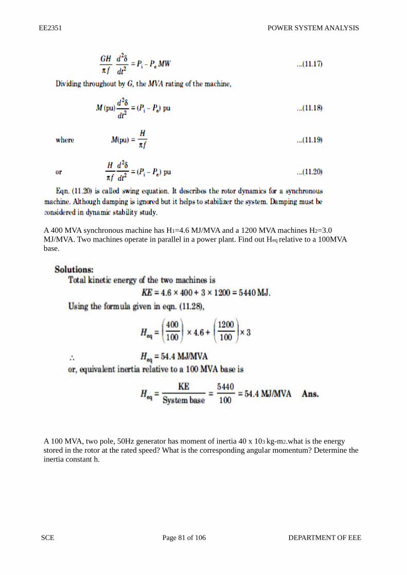
A 400 MVA synchronous machine has H1=4.6 MJ/MVA and a 1200 MVA machines H2=3.0
MJ/MVA. Two machines operate in parallel in a power plant. Find out Heq relative to a 100MVA
base.
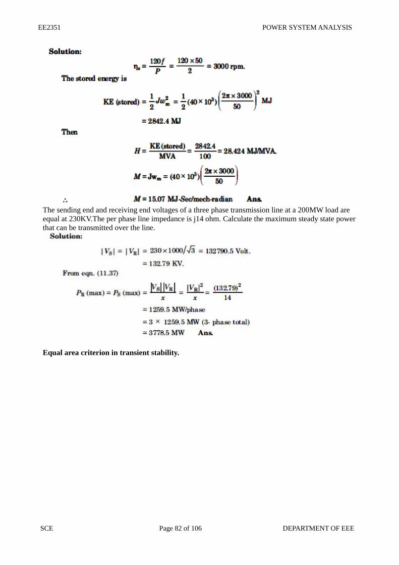
A 100 MVA, two pole, 50Hz generator has moment of inertia 40 x 103 kg-m2.what is the energy
stored in the rotor at the rated speed? What is the corresponding angular momentum? Determine the
inertia constant h.
EE2351 POWER SYSTEM ANALYSIS
SCE Page 82 of 106 DEPARTMENT OF EEE
The sending end and receiving end voltages of a three phase transmission line at a 200MW load are
equal at 230KV.The per phase line impedance is j14 ohm. Calculate the maximum steady state power
that can be transmitted over the line.
Equal area criterion in transient stability.
EE2351 POWER SYSTEM ANALYSIS
SCE Page 83 of 106 DEPARTMENT OF EEE
EE2351 POWER SYSTEM ANALYSIS
SCE Page 84 of 106 DEPARTMENT OF EEE
A single line diagram of a system is shown in fig. All the values are in per unit on a common base.
The power delivered into bus 2 is 1.0 p.u at 0.80 power factor lagging. Obtain the power angle
equation and the swing equation for the system. Neglect all losses.
EE2351 POWER SYSTEM ANALYSIS
SCE Page 85 of 106 DEPARTMENT OF EEE
EE2351 POWER SYSTEM ANALYSIS
SCE Page 86 of 106 DEPARTMENT OF EEE
5.5 CRITICAL CLEARING ANGLE AND CRITICAL CLEARING TIME IN TRANSIENT
STABILITY.
EE2351 POWER SYSTEM ANALYSIS
SCE Page 87 of 106 DEPARTMENT OF EEE
EE2351 POWER SYSTEM ANALYSIS
SCE Page 88 of 106 DEPARTMENT OF EEE
2 MARK QUESTIONS WITH ANSWERS
UNIT I - POWER SYSTEM ANALYSIS
1. What are the main divisions of power system. OR What are the functions of modern power system
Nov/Dec-2014, Nov/Dec-2013
There are three main divisions in power system
a) Generation System
b) Transmission system
c) Distribution system
2. What is single line diagram? Or What is the meaning of one line diagram of a power system?
April / May 2010, November / December 2011, May / June 2012, Nov / Dec 2007
A single line diagram is a diagrammatic representation of power system in which the components are
represented by their symbols and the interconnection between them are shown by a single straight line.
3. What are the components of a power system? Or List the different components of power system. April /
May 2008,May / June 2012
The components of a power system are Generators, Power transformers, Transmission lines, Substation
transformers, Distribution transformers and Loads.
4. Define per unit value. Or Define per unit value of an electrical quantity. Write equation for base impedance
with respect to 3-phase system. May / June 2009
The per unit value of any quantity is defined as the ratio of actual value of the quantity to base value of the
quantity.
Per unit = Actual value
Base value
5. What is the need for base value? Or what is the need of per unit value. Nov/Dec-2014
The components or various sections of power system may operate at different voltage and power
levels. It will be convenient for analysis of power system if the voltage, power, current and impedance
ratings of components of power system are expressed with a common value called base value. Hence for
analysis purpose a base value is chosen for voltage, power, current and impedance.
6. What is the need for system analysis in planning and operation of power system? May / June
2007, Nov / Dec 2008 Planning the operation of a power system requires load studies, fault calculations,the design of means for
protecting the system against lightning and switching surges and against short circuits, and studies of the
stability of the system
7. What are the quantities whose base values are required to represent the power system by reactance
diagram? Or .
How are the base values chose in per unit representation of a power system? Nov / Dec 2008
The base value of voltage, current, power and impedance are required to represent
the power system by reactance diagram. Selection of base values for any two of them
determines the base values of the remaining two. Usually the base values of voltage and power are chosen
in kilovolt and kVA or mVA respectively. The base values of current and impedance are calculated
using the chosen bases.
EE2351 POWER SYSTEM ANALYSIS
SCE Page 89 of 106 DEPARTMENT OF EEE
8. Write the equation for converting the p.u. impedance expressed in one base to another. April / May 2010
9. What are the advantages of per unit computations? Or What are the advantages of per unit system?
May / June 2007, April / May 2008, April / May 2011
a) Manufacturers usually specify the impedance of a device or machine in per unit on the basis of the name
plate details.
b) The p.u. values of widely different rating machines lie within a narrow range even though the ohmic values
has a very large range.
c) The p.u. impedance of circuit element connected by a transformer expressed on a proper base will be same
if it is referred to either side of a transformer.
d) The p.u. impedance of a 3-phase transformer is independent of the type winding connection.
10. What are the approximations made in impedance diagram?
a) The neutral reactances are neglected.
b) The shunt branches in equivalent circuit of induction motor are neglected.
11. What are the approximations made in reactance diagram?
a) The neutral reactance are neglected.
b) The shunt branches in equivalent circuit of induction motor are neglected.
c) The resistances are neglected.
d) All static loads and induction motor are neglected.
e) The capacitances of the transmission lines are neglected.
12. How are the loads represented in reactance or impedance diagram? Nov / Dec- 2011
The loads represented in reactance or impedance diagram which is the combination of resistance and inductive
reactance in series.
13. Give the equations for transforming base kV on LV side to HV side and viceversa. Or Write the equation
for converting the p.u. impedance expressed in one base to another base. April / May 2010
Base kV on HT side = Base kV on LT side * (HT voltage rating / LT voltage rating)
Base kV on LT side = Base kV on HT side * (LT voltage rating / HT voltage rating)
14. Define steady state operating condition. Nov/Dec-2012
A power system is said to be in a steady state operating condition, if all the
measured(or calculated) physical quantities describing the operating condition of the
system can be considered constant for the purpose of analysis.
15. When is a power system said to be steady-state stable? Nov/Dec-2012
The power system is steady state stable for a particular steady-state operating
condition if, following a small disturbance, it returns to essentially the same steady state
condition of operation.
16. When is a power system said to be transiently stable? Nov/Dec-2012
If the machines of the system are found to remain essentially in synchronism
within the first second following a system fault or other large disturbance, the system is
considered to be transiently stable.
17. What is transient state of the power system? Nov/Dec-2012
EE2351 POWER SYSTEM ANALYSIS
SCE Page 90 of 106 DEPARTMENT OF EEE
The state of the system in the first second following a system fault or large
disturbance is called the transient state of the power system.
18. If the reactance in ohms is 15 ohms, find the p.u value for a base of 15 KVA and 10 KV. May / June 2012
19. What is a bus?
The meeting point of various components in a power system is called a bus.
20. What is bus admittance matrix?
The matrix consisting of the self and mutual admittance of the network of a power system is called bus
admittance matrix.
21. Explain bus incidence matrix. Or Define bus incidence matrix. Nov / Dec 2008, May / June 2012
For the specific system, we can obtain the following relation (relation between element voltage
and bus voltage).
V = A VBUS where A is the bus incidence matrix, which is a rectangular and singular matrix. Its
elements are found as per the following rules.
aik = 1, if ith element is incident to and oriented away from the k
th node (bus).
= -1, if ith element is incident to but oriented towards the k
th node.
= 0, if ith element is not incident to the k
th node.
22. Define primitive network. Or Describe primitive network. Give an example. April / May 2010 Primitive network is a set of unconnected elements which provides information regarding the characteristics of individual elements only. The performance equations of primitive network are given below.
V + E = ZI (In Impedance form)
I + J = YV (In Admittance form) where V and I are the element voltage and current vectors respectively.
J and E are source vectors.
Z and Y are the primitive Impedance and Admittance matrices respectively.
23. What is bus admittance matrix? (MAY/JUNE 2006)
The matrix consisting of the self and mutual admittance of the power system network is called bus admittance matrix. It is given by the admittance matrix Y in the node basis matrix equation of a power system and it is denoted as Ybus. Bus admittance matrix is a symmetrical matrix.
24. What is Jacobian matrix? How the elements of Jacobian matrix are computed? April / May 2011
EE2351 POWER SYSTEM ANALYSIS
SCE Page 91 of 106 DEPARTMENT OF EEE
The matrix formed from the derivates of load flow equations is called Jacobian matrix and it is denoted by J. The elements of Jacobian matrix will change in every iteration. In each iteration, the elements of the Jacobian matrix are obtained by partially differentiating the load flow equations with respect o unknown variable and then evaluating the first derivates usingthe solution of previous iteration.
25. Name the diagonal and off-diagonal elements of bus admittance matrix.Nov/Dec-2013
The diagonal elements of bus admittance matrix are called self admittances of the matrix and off-diagonal
elements are called mutual admittances of the buses.
26. Write the equation to find the elements of new bus admittance matrix after eliminating nth row and column
in a n*n matrix.
Yjk = Yjk-(YjnYnk / Ynn)
27. What is bus impedance matrix?
The matrix consisting of driving point impedances and transfer impedances of the network of a power
system is called bus impedance matrix.
28. Name the diagonal and off-diagonal elements of bus impedance matrix. Nov/Dec-2013
The diagonal elements of bus impedance matrix are called driving point impedances of the buses and
off-diagonal elements are called transfer impedances of the buses.
29. What are the methods available for forming bus impedances matrix?
a) Form the bus admittances matrix and then take its inverse to get bus impedance matrix.
b) Directly from the bus impedance matrix from the reactance diagram. This method utilizes the techniques of
modification of existing bus impedance matrix due to addition of new bus.
30. Write the four ways of adding an impedance to an existing system so as to modify bus impedance matrix.
a) Case 1:Adding a branch impedance Zb from a new bus P to the reference bus.
b) Case 2:Adding a branch impedance Zb from a new bus P to the existing bus q.
c) Case 3:Adding a branch impedance Zb from a existing bus q to the reference bus.
d) Case 4:Adding a branch impedance Zb between two existing bus h and q.
31. What is off-nominal transformer ratio?
When the voltage or turns ratio of a transformer is not used to decide the ratio of base kV then its voltage or
turns ratio is called off-nominal turns ratio.
32. Draw a simple per-phase model for a cylindrical rotor synchronous machine? April / May 2011
EE2351 POWER SYSTEM ANALYSIS
SCE Page 92 of 106 DEPARTMENT OF EEE
EE2351 POWER SYSTEM ANALYSIS
SCE Page 93 of 106 DEPARTMENT OF EEE
UNIT II-POWER FLOW ANALYSIS
1. What is power flow study? Nov/Dec-2014
The study of various methods of solution to power system network is reffered to as power flow or load flow
study.
2. What are the informations that are obtained from a load flow study?
The information obtained from a load flow study are magnitude and phase of bus voltages, real and reactive
power flowing in each line and the line losses. The load flow solution also gives the initial conditions of the
system when the transient behaviour of the system is to be studied.
3. What is the need for load flow study?Nov/Dec-2012,May/June-2013
The load flow study of a power system is essential to decide the best operation of existing system and for
planning the future expansion of the system. Also essential for designing a new system.
4. What are the works involved in a load flow study?
a) Representation of the system by single line diagram.
b) Determining the impedance diagram using the information in single line diagram.
c) Formulation of network equations.
d) Solution of network equations.
5. What are the quantities that are associated with each bus in a system?
Each bus in a system are associated with four quantities and they are real power,reactive power, magnitude of
voltage and phase angle of voltage.
6. What are the different types of buses?
a) Load bus or PQ bus
b) Generator bus or voltage controlled bus or PV bus
c) Slack bus or Swing bus or Reference bus.
7. Define voltage controlled bus. Nov/Dec-2014
A bus is called voltage controlled bus if the magnitude of voltage and real power are specified. The magnitude
of voltage is not allowed to change.
8. What is PQ bus?
A bus is called PQ are load bus when real and reactive components of power are specified for the bus. In a load
bus the voltage is allowed to vary within the permissible value.
9. What is swing bus(slack bus/reference bus)?
A bus is called swing bus when the magnitude and phase of bus voltage are
specified for it. The swing bus is the reference bus for load flow solution and it is
required for accounting for the line losses. Usually one of the generator bus is selected as
the swing bus.
10. What is the need for slack bus? (APR/MAY 2004),(NOV/DEC 2004),Nov/Dec-2013
The slack bus is needed to account for transmission line losses. In a power system, the total power
generated will be equal to sum of power consumed by loads and losses. In a power system, only the generated
power and load power are specified for the buses. The slack bus is assumed to generate the power
required for losses. Since the losses are unknown, the real and reactive power are not specified for slack bus.
They are estimated through the solution of line flow equations.
11. What is the need for slack bus?
The slack bus is needed to account for transmission losses.
EE2351 POWER SYSTEM ANALYSIS
SCE Page 94 of 106 DEPARTMENT OF EEE
12. What is PQ bus(load bus)? (APR/MAY 2005)
A bus is called PQ bus or load bus when real and reactive components of power are specified for the bus. In a load
bus, the voltage is allowed to vary within permissible limits.
13. List the quantities specified and the quantities to be determined from load flow
study for various types of buses. (MAY/JUNE 2006)
The following table shows the quantities specified and the quantities to be
obtained for various types of buses.
Bus type Quantities Quantities to specified be obtained
Load Bus P,Q |V|, δ
Generator Bus P, |V| Q, δ
Slack Bus |V|, δ P, Q
14. What are the iterative methods used for solution of load flow problems?
Guass-Seidal (GS) method and Newton Raphson(NR) method.
15. Why do we go for iterative methods to solve load problems?
The load flow equations are nonlinear algebraic equations and so explicit solution is not possible. The solution
of nonlinear equations can be obtained only by iterative numerical techniques.
16. When the generator bus is treated as load bus?May/June-2011
If the reactive power of a generator bus violates the specified limits then the generator bus is treated as load
bus.
17. What are the advantages of GS method?
(i) Calculations are simple and so the programmimg task is lesser.
(ii) The memory requirement is less.
(iii) Useful for small systems.
18. What are the disadvantages of GS method?
a) Requires large number of iterations to reach convergence.
b) Not suitable for large systems.
c) Convergence time increases with size of the system.
19. What are the advantages of NR method?
1. Faster, more reliable and the results are accurate.
2. Requires less number of iterations to reach convergence.
3. The numbers of iterations are independent of the size of the system.
4. Suitable for large systems.
20. What are the disadvantages of NR method?Nov/Dec-2011
(i) The programming is more complex.
(ii) Memory requirement is more.
(iii) Computation time per iteration is higher due to large number of calculations per iterations.
21. Write the most important mode of operation of power system and mention the
EE2351 POWER SYSTEM ANALYSIS
SCE Page 95 of 106 DEPARTMENT OF EEE
major problems encountered with it. Symmetrical steady state is the most important mode of operation of power
system. Three major problems are encountered in this mode of operation. They are,
a) Load flow problem
b) Optimal load scheduling problem
c) Systems control problem
22. What are the different types of buses in a power system? The buses of a power system can be classified into three types based on the
quantities being specified for the buses, which are as follows:
a) Load bus or PQ bus (P and Q are specified)
b) Generator bus or voltage controlled bus or PV bus (P and V are specified)
c) Slack bus or swing bus or reference bus (|V| and δ are specified)
23. Compare G-S method and N-R methods of load flow solutions.
G-S method N-R method 1. The variables are expressed in 1. Variables are expressed in polar co-
rectangular co-ordinates. ordinates.
2. Computation time per iteration is
less.
2. Computation time per iteration is
more 3. It has linear convergence characteristics.
3. It has quadratic convergence
characteristics.
4. The number of iterations required for 4.The number of iterations are
independent
convergence increase with size of
the
of the size of the system.
system.
5.The choice of slack bus is critical. 5. The choice of slack bus is arbitrary.
24. Write the equation for power flow in the transmission line.
The equation for power low in the transmission line (say p-q) at bus ‘p’ is given by,
Spq = Ppq-jQpq = Ep* ipq
= Ep*[Ep-E
q]Y
pq + Ep*Ep.(Y
pq’/2)
Sqp = Pqp-jQqp = Eq* iqp
= Eq*[Eq-E
p]Y
pq + Eq*Eq.(Y
pq’/2)
25. Discuss the effect of acceleration factor in the load flow solution algorithm.
(APR/MAY 2004) ,Nov/Dec-2012
In load flow solution by iterative methods, the number of iterations can be
reduced if the correction voltage at each bus is multiplied by some constant. The
multiplication of the constant will increase the amount of correction to bring the voltage closer to
the value it is approaching. The multipliers that accomplish this improved converged
are called acceleration factors. An acceleration factor of 1.6 is normally used in load flow problems.
26. Why do Ybus used in load flow study instead of Zbus? Nov/Dec-2013
EE2351 POWER SYSTEM ANALYSIS
SCE Page 96 of 106 DEPARTMENT OF EEE
The Ybus is used in load flow study instead of Zbus because of it is symmetrical along the leading
diagonal.Many of the off diagonal elements are zero.Therefore it is easy to analyse.
27. When will the generator bus to be treated as load bus ? Nov/Dec-2013
If the iterative power of a generator bus violates the specified limits then the generator bus is treated
as load bus.
What ARE THE DATA RE
28. why power flow analysis is made? or what are the datas required power flow studies ? Nov/Dec-2012
Power flow analysis is performed to calculate the magnitude and phase angle of
voltages at the buses and also the active power and reactive voltamperes flow for
the given terminal or bus conditions. The variables associated with each bus or node are,
a. Magnitude of voltage |V|
b. Phase angle of voltage δ
c. Active power, P
d. Reactive voltamperes, Q
EE2351 POWER SYSTEM ANALYSIS
SCE Page 97 of 106 DEPARTMENT OF EEE
PART B – 16 marks
1. The one line diagram of a power system is shown in figure. The three phase power and line
to line ratings are given below.
2012)
(Nov/Dec
G
T1
T2
:
:
:
80 MVA
50 MVA
40 MVA
22kV
22/220kV
220/22kV
X=9%
X=10%
X=6%
T3, T4 :
Line 1 :
Line 2 :
40 MVA 22/110kV
200kV
110kV
X=6.4%
X=121Ω
X=42.35Ω
M : 68.85 MVA 20kV X=22.5%
Load :
2. Draw the reactance diagram for the power system shown in figure. Neglect resistance and
use a base of 100 MVA, 220 kV in 50Ω line. The ratings of the generator, motor and
transformer are given below.
(May/June 2012)
Generator
Synchronous motor
Y-Y Transformer
Y-Δ Transformer
: 40 MVA, 25 kV, X’’ =20%
: 50 MVA, 11 kV, X’’ =30%
: 40 MVA, 33/220 kV, X=15%
: 30 MVA, 11/220 kV, X =15%
EE 2351 POWER SYSTEM ANALYSIS
SCE Page 98 of 106 DEPARTMENT OF EEE
3. The single line diagram of an unloaded power system is shown in Figure. Reactances of the two
sections of the transmission line are shown on the diagram. The generators
and
transformers are rated as follows:
Generator 1: 20 MVA, 11 kV, Xd’’= 0.25 Per unit
Generator 2: 30 MVA, 18 kV, Xd’’= 0.25 Per unit
Generator 3: 30 MVA, 20 kV, Xd’’= 0.21 Per unit
Transformer 1: 25 MVA, 220/13.8 kV, X= 0.15 Per unit
Transformer 2: single phase units, each rated 10 MVA 127/18 kV, X= 0.15 Per unit
Transformer 3: 35 MVA, 220/22 kV, X= 0.15 Per unit
Draw the impedance diagram with all reactance’s marked in per unit. Choose a base of 50 MVA, 11 kV in the
circuit of generator)Draw the impedance diagram showing all impedances in per unit on a 100 MVA
base.Choose 22 kV as the voltage base for generator.(12)
EE 2351 POWER SYSTEM ANALYSIS
SCE Page 99 of 106 DEPARTMENT OF EEE
UNIT III & IV-FAULT ANALYSIS – BALANCED AND UNBALANCED
1. What is meant by a fault? May/June-2014
A fault in a circuit is any failure which interferes with the normal flow of current. The faults are associated
with abnormal change in current, voltage and frequency of the power system.
2. Why fault occur in a power system?
The faults occur in a power system due to insulation failure of equipments,flashover of lines initiated by a
lightning stroke, due to permanent damage to conductors and towers or due to accidental faulty operations.
3. List the various types of shunt and series faults.May/June-2014
The various types of shunt faults are:
(i)Line to Ground fault (ii) Line to Line fault
(iii)Double line to Ground fault (iv) Three phase fault
The various types of series faults are:
(i)One open conductor fault (ii) Two open conductor fault
4. What is symmetrical and unsymmetrical fault? Noc/Dec-2014
The fault is called symmetrical fault if the fault current is equal in all the phases. The fault is called
unsymmetrical fault if the fault current is not equal in all the phases.
5. Distinguish between Symmetrical short Circuits and unsymmetrical short Circuits.Noc/Dec-2012
Symmetrical short Circuits Unsymmetrical Short Circuits
Fault Currents are equal in all the phases Fault currents are unbalanced
Analyzed on per phase basis Analyzed only using symmetrical components
6. Name any two methods of reducing short –circuit current.
a. By providing neutral reactance.
b. By introducing a large value of shunt reactance between buses.
7. What is meant by fault calculations?
The fault condition of a power system can be divided into subtransient, transient and steady state periods.
The currents in the various parts of the system and in the fault are different in these periods. The estimation
of these currents for various types of faults at various locations in the system are commonly referred to as
fault calculations.
8. What is the need for short circuit studies or fault analysis? Nov/Dec-2014, Nov/Dec-2012,May/June-2011
The short circuit studies are essential in order to design or develop the protective schemes for various parts
of the system. The protective schemes consists of current and voltage sensing devices , protective relays and
circuit breakers. The selection of these devices mainly depends on various currents that may flow in the
fault conditions.
9. What are the assumptions made in short circuit studies of a large power system
network? (APR/MAY 2005)
a) The phase to neutral emfs of all generators remain constant, balanced and unaffected by the
faults.
b) Each generator is represented by an emf behind either the subtransient or transient reactance
depending upon whether the short circuit current is to be found immediately after the short circuit
or after about 3 – 4 cycles.
EE 2351 POWER SYSTEM ANALYSIS
SCE Page 100 of 106 DEPARTMENT OF EEE
c) Load currents may often be neglected in comparison with fault currents.
d) All network impedances are purely reactive. Thus the series resistances of lines and transformers
are neglected in comparison with their resistances.
e) Shunt capacitances and shunt branches of transformers are neglected. Hence,
transformer reactances are taken as their leakage reactances.
10. Draw the sequence networks for a ∆-∆ connected transformer.NovDec-2012
11. What is synchronous reactance?
The synchronous reactance is the ratio of induced emf and the steady rms current. It is the sum of leakage
reactance and the reactance representing armature reaction.
12. Define subtransient reactance.
The subtransient reactance is the ratio of induced emf on no load and the subtransient symmetrical rms
current.
13. Define transient reactance.
The subtransient reactance is the ratio of induced emf on no load and the transient symmetrical rms current.
14. Name the fault in which positive, negative and zero sequence component currents are equal.
In Single line to ground fault positive, negative and zero sequence component currents are equal.
15. What is sequence network April/May-2011
16. Name the fault in which positive and negative sequence component currents together is equal to zero
sequence current in magnitude.May/June-2012,Nov/Dec-2011
Double line to ground fault.
17. What are symmetrical components? Nov/Dec-2014,Nov/Dec-2012 An unbalanced system of N related vectors can be resolved into N systems of balanced vectors called symmetrical components.
a) Positive sequence components b) Negative sequence components c) Zero sequence components.
18. Define positive sequence impedance.
The positive sequence impedance of an equipment is the impedance offered by the equipment to the flow of
The negative sequence impedance of an equipment is the impedance offered by the equipment to the flow
of negative sequence currents.
20. What are the features of zero sequence current
Zero sequence components consist of three phasors equal in magnitude and with zero phase displacement
from each other. Vao, Vbo and Vco are the zero sequence
components of Va, Vb and Vc.
21. Write the boundary condition in single line to ground fault.
Va = 0 ; Ib = Ic = 0
22. What are the boundary conditions in line to line fault?
Ia = 0 ; Ib + Ic = 0 ; Vb = Vc
23. Write down the boundary condition in double line to ground fault.
Ia = 0 ; Vb = 0 ; Vc= 0
24. Give the boundary condition for 3-phase fault.
Ia + Ib = Ic = 0 ; Va = Vb = Vc= 0
UNIT- III
PART B 16 Marks
1. A symmetrical fault occurs on bus 4 of system shown in fig. determine the fault current, post fault
voltages and line currents using thevenins method.
2. For a
radial network shown a 3 phase fault occurs at F. determine the fault current and
the line voltage at 11 KV bus under fault conditions
(Nov/Dec 12)
3. Explain the computational procedure of fault
analysis using bus building algorithm(May/ Jun 2013)
4. A synchronous generator and motor are rated 30 MVA , 13.2 kv
and both have sub transient reactance of 20%. The line
connecting them has a reactance of 10% on the base of machine
rating. The motor is drawing 20000 KW at 0.8 pf lagging and
terminal
EE 2351 POWER SYSTEM ANALYSIS
SCE Page 102 of 106 DEPARTMENT OF EEE
voltage of 12.8 KV. When a symmetrical 3 phase fault occurs at the midpoint of the transmission line. Find the
subtransient current in the generator, motor and fault by using the internal voltage of the machines.(Nov/Dec
2009)
5. A synchronous generator rated rated at 500 KVA, 440V, 0.1 p.u subtransient reactance is supplying a
passive load of 400 KW at 0.8 pf lagging. Calculate the intial symmetrical
RMS current for a 3 phase fault at the generator terminals.
6. Figure shows two generating stations feeding a 132 KV system. Determine the total fault current, fault level
and fault current supplied by each alternator for a 3 phase solid fault at the receiving bus. The length of
the transmission line is 150 km. (Nov/Dec 2011)
7. The generators at bus 1 and 3 of the
network have impedances of j1.5 .if a 3
phase short circuit fault occurs at
bus 3 and at bus 2 when
there is no load. Find the
initial symmetrical current in fault, line Flows
and the post fault voltages using bus building algorithm.
A symmetrical fault occurs on bus 4 of system shown in fig. determine the fault current,
post fault voltages and line currents using bus building algorithm.
8. A three phase 5 MVA, 6.6kV alternator with a reactance of 8% I connected to a feeder of series impedance of
0.12+j0.48 ohm/phase/km through a step up transformer. The transformer is rated at 3MVA, 6.6/33kV and has
a reactance of 5%. Determine the fault current supplied by the generator operating under no load with a
voltage of 6.9kV, when a 3 phase symmetrical fault occurs at a point 15km long the feeder (May/June 2012)
9. Two generators G1 and G2 opposite to each other are connected to two transformers T1 and T2 respectively through a transmission line of 60km long, each conductor ha a reactance 0.92Ω/ km . Generator G1 and G2 are identical and rated as 11kV, 30 MVA and have a transient reactance of 0.3 pu at on MVA base. The transformers T1 and T2 are identical and are rated 11/66kV, 10 MVA and have a reactance of 0.075 per unit to their own base. The three phase fault is assumed at point F, which is 25km from generator G1. Find the short circuit current.
10. A 11 KV, 100 MVA alternator having a sub-transient reactance of 0.25 pu is supplying a 50 MVA motor
having a sub-transient of 0.2 pu through a transmission line. The line reactance is0.05 pu on the base of
100 MVA. The motor is drawing 40 MW at 0.8 p.f leading with a terminal voltage of 10.95 KV when a three
phase fault occurs at the generator terminals. Calculate the total current in generator
and motor under fault condition. (16) (Apr/May 2011)
11. Two synchronous motor are connected to the bus of large system through a short transmission line.
the ratings of various components are motor(each) : 1 MVA 440V 0.1 PU transient reactance , Line:
0.05 ohm (reactance) large system : short circuit MVA as its bus at 440.V is 8 . when the motors
are operating at 440V calculate the short circuit current (symmetrical) fed into a three phase
fault at motor bus.(Apr/May 2010)
EE 2351 POWER SYSTEM ANALYSIS
SCE Page 103 of 106 DEPARTMENT OF EEE
UNIT -IV
PART B 16 marks
1. Draw the sequence network connection for double line to ground fault at any point of in a power system
and from that obtain the expression for the fault current (Nov/Dec 2012)
2. Derive the expression for L-G fault and L-L fault which is grounded through impedance Z f. (May/ June 12)
3. Derive the expression for LL-G fault which is grounded through impedance Zf.
4. What are the assumptions to be made in short circuit studies. Deduce and draw the sequence network for a
line to line fault & L-G at the terminals of an unloaded generator and from that obtain the expression for
the fault current (solidly grounded) (Apr/May 2011)
5. Determine the fault current for the following faults using bus impedance matrix
a) Balanced 3 phase fault at bus 3 through fault impedance Zf.=0.1j b) Single line to ground fault at bus 3 through fault impedance Zf.=0.1j
6. A 50 MVA, 11 kV, 3φ alternator was subjected to different types of faults. The fault currents are 3φ fault
1870 A, line to line fault 2590 A, single line to ground fault 4130 A. The alternator neutral is solidly
grounded. Find the pu values of the three sequence reactance’s of the alternator. (May/June 2012)
7. A 30 MVA, 11 kV generator has Z1=Z2=j0.2 pu and Z0=j0.05 pu. A line to ground fault occurs on the
generator terminals. Find the fault current and line to line voltages during fault conditions. Assume that the
generator neutral is solidly grounded and that the generator is operating at no load and at rated voltage at
the occurrence of fault. (May/June 2012)
8. Discuss in detail about the sequence impedance of and networks of synchronous machine, transformer,
transmission line and loads (May/June 2013)
9. Derive an expression for the total power in a three phase system interms
of sequence components of voltages and currents (Nov/Dec 2012)
10. A single line diagram is shown in the fig. generator grounding reactance is 0.5 pu. draw the sequence
networks and calculate the fault current for line to line fault on phase b and c at point Q assume prefault
voltage is 1.0 pu (May/Jun 2013)
EE 2351 POWER SYSTEM ANALYSIS
SCE Page 104 of 106 DEPARTMENT OF EEE
UNIT V – STABILITY ANALYSIS
1. Define stability.
The stability of the system is defined as the ability of the system to return to stable operation when it is
subjected to a disturbance.
2. Define steady state stability.
Steady state stability is defined as the ability of the power system to remain stable i.e,without loosing
synchronism for small disturbances.
3. Define transient stability.May/June-2012
Steady state stability is defined as the ability of the power system to remain stable i.e,without loosing
synchronism for large disturbances.
4. Define synchronizing or stiffness coefficient. For what value of synchronizing coefficient the system
remains stable.
The term Pmax Cos ᵟo is called synchronizing or stiffness coefficient. The system is stable if the
synchronizing or stiffness coefficient is positive.It is positive when 0 < ᵟo < π/2.
5. Give an expression for swing equation. Nov/Dec-2011
(H/ πf)(d2ᵟ/dt
2) = Pm – Pe
6. Define swing curve.
The swing curve is the plot or graph between the power angle and time.
7. What is the use of swing curve?
It is usually plotted for a transient state to study the nature of variation in power angle for a sudden large
disturbance. From the nature of variation in power angle the stability of a system for any disturbance can be
determined.
8. Define power angle.
The power angle or torque angle is defined as the angular displacement of the rotor from synchronously
rotating reference frame.
9. Name the two ways by which transient stability study can be made in a system where one machine is
The critical clearing angle is the maximum allowable change in the power angle before clearing the fault,
without loss of synchronism.
The critical clearing time is defined as the maximum time delay that can be allowed to clearing fault,
without loss of synchronism.
11. what are sequence impedances and sequence networks? Nov/Dec-2014
The sequence impedances are the impedances offered by the devices or components for the
like sequence component of the current.
The single phase equivalent circuit of a power system consisting of impedances to current of any one
sequence only is called sequence network.
12. What is meant by an infinite bus? Nov/Dec-2012
The connection or disconnection of a single small machine on a large system would
not affect the magnitude and phase of the voltage and frequency. Such a system of
constant voltage and constant frequency regardless of the load is called infinite bus bar
system or infinite bus.
13. What is transient stability limit? May/June-2012
When the load on the system is increased suddenly, maximum power that can be transmitted without losing
synchronism is termed as transient state stability limit. Normally, steady state stability limit is greater than
transient state stability limit.
14. List the methods of improving the transient stability limit of a power system.
a) Increase of system voltage and use of Automatic Voltage Regulation (AVR)
b) Use of high speed excitation systems.
c) Reduction in system transfer reactance.
d) Use of high speed reclosing breakers.
State equal area criterion.
15. State Equal area criterion.Nov/Dec-2004,May/June-2013,Nov/Dev-2012
In a two machine system under the usual assumptions of constant input , no damping
and constant voltage being transient reactance , the angle between the machines either
increases or else, after all disturbances have occurred oscillates with constant amplitude. There is a simple graphical method of determining whether the system comes to rest with
respect to each other. This is known as equal area criterion
Equal area criterion for stability states that the system is stable if the area under Pa - ᵟ curve reduces to zero
at some value of ᵟ.
This is possible only if the positive area under Pa - ᵟ curve is equal to the negative area under
Pa - ᵟ curve for a finite change in ᵟ.hence this stability criterion is called Equal area criterion.
16. What are the assumptions made in short circuit studies of a large power system
network? (APR/MAY 2005)
a) The phase to neutral emfs of all generators remain constant, balanced and unaffected
by the faults.
b) Each generator is represented by an emf behind either the subtransient or transient reactance depending
upon whether the short circuit current is to be found immediately
EE 2351 POWER SYSTEM ANALYSIS
SCE Page 106 of 106 DEPARTMENT OF EEE
after the short circuit or after about 3 – 4 cycles.
c) Load currents may often be neglected in comparison with fault currents.
d) All network impedances are purely reactive. Thus the series resistances of lines and
transformers are neglected in comparison with their resistances.
e) Shunt capacitances and shunt branches of transformers are neglected. Hence, transformer reactances
are taken as their leakage reactances.
17. How do you classify steady state stability limit. Define them. May/June-2013
Depending on the nature of the disturbance, the steady state stability limit is
classified into,
a) Static stability limit refers to steady state stability limit that prevails without
the aid of regulating devices.
b) Dynamic stability limit refers to steady state stability limit prevailing in an
unstable system with the help of regulating devices such as speed governors,
voltage regulators, etc.
18. What are coherent machines? (APR/MAY 2004) May/June -2013
Machines which swing together are called coherent machines. When both ωs and δ are expressed in
electrical degrees or radians, the swing equations for coherent machines can be combined
together even though the rated speeds are different. This is used in stability studies involving many
machines.
Part B -16 marks
1. Describe R.K method of solution of swing equation for SMIB system (16)
(Apr/May 2011)
2. Derive an expression for critical clearing angle and clearing time (April-2011)
3. Derive the swing equation for a single machine connected to an infinite bus system. (May/June
2013)
4. State and explain equal area criterion. Indicate how you will apply equal area criterion to find maximum
additional load that can be suddenly added. (May/June 2013)
5. With a neat flow chart, explain how the transient stability study can be made by modified Euler method.
(Nov/Dec 2012)
6. A three generator delivers 1 pu, power to an infinite bus through a transmission network when a fault occurs. The
maximum power which can be transferred during pre fault, during fault and post fault conditions is 1.75 pu,