55
A coverage on safety valve
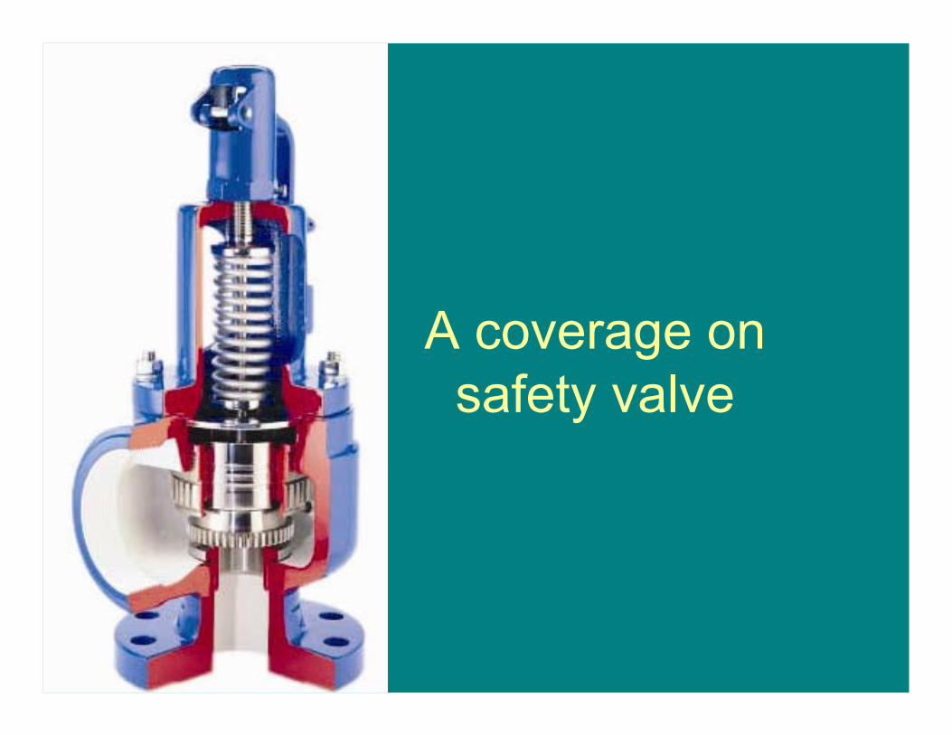
A coverage on safety valve
Purpose of safety valve
• To safeguard the equipment against exceeding design pressure.
• A boiler without Superheater will have two safety valves in steam drum / Shell.
• A boiler with superheater should have one safety valve on superheater & two safety valves on Steam drum.
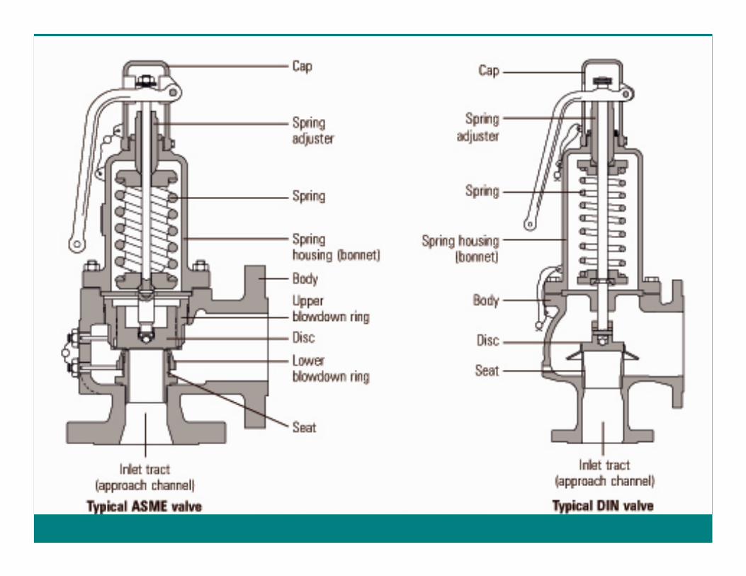
A safety valve versus relief valve
• A relief valve is meant for releasing the liquid in a proportional manner in order to maintain some system pressure on a continual basis.
• A safety valve should instantly lift and release the medium by a fixed quantity and bring down the pressure.
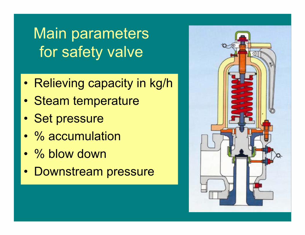
Main parameters for safety valve
• Relieving capacity in kg/h• Steam temperature • Set pressure• % accumulation• % blow down• Downstream pressure
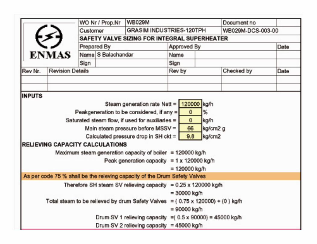
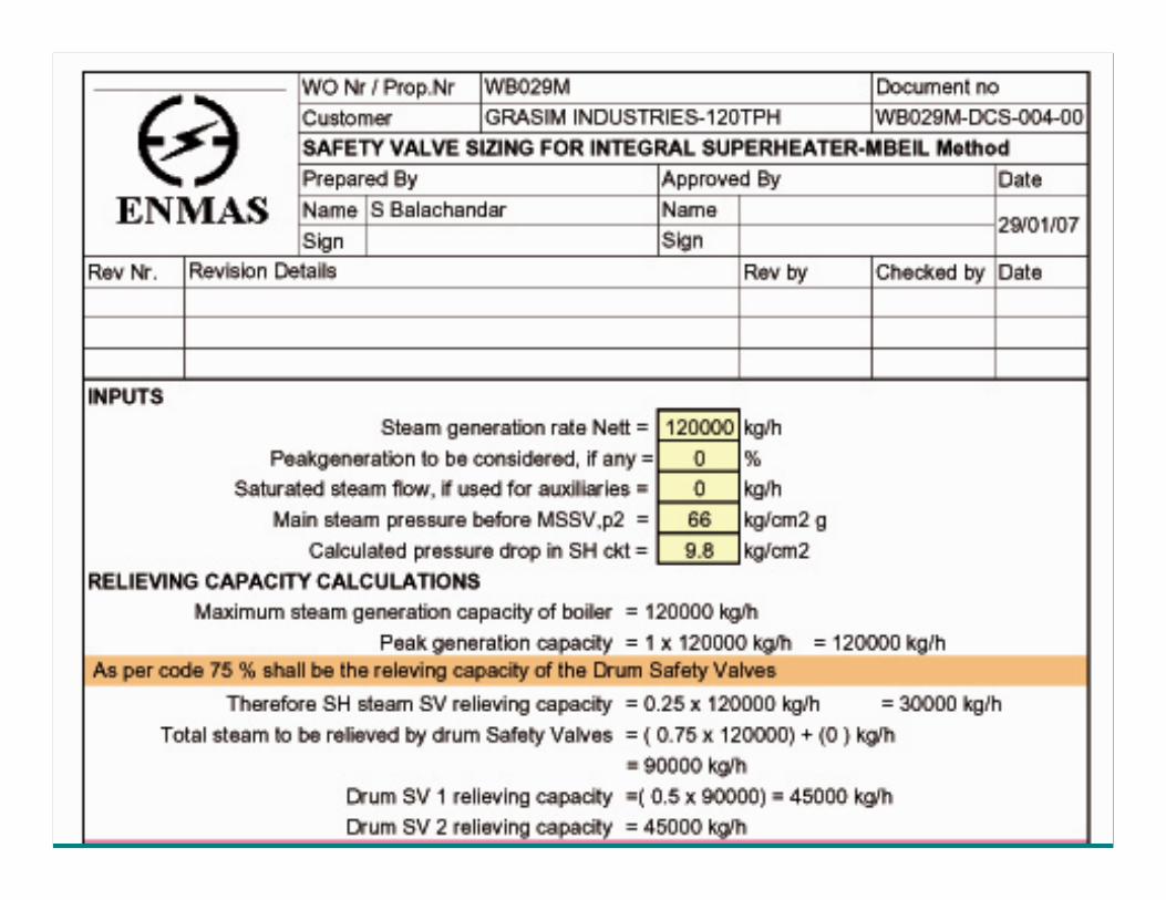
Relieving capacity of safety valves for a boiler
• All the safety valves put together should relieve the entire steam that is generated by the boiler without casing an increase in pressure by 5%.
• The drum safety valves together should release 75% Boiler steam generation capacity.
Electromatic safety valve
• An electromatic safety valve is a pressure switch initiated safety valve which is set to lift on particular pressure.
• Whereas a regular safety valve can lift only after an accumulation of pressure
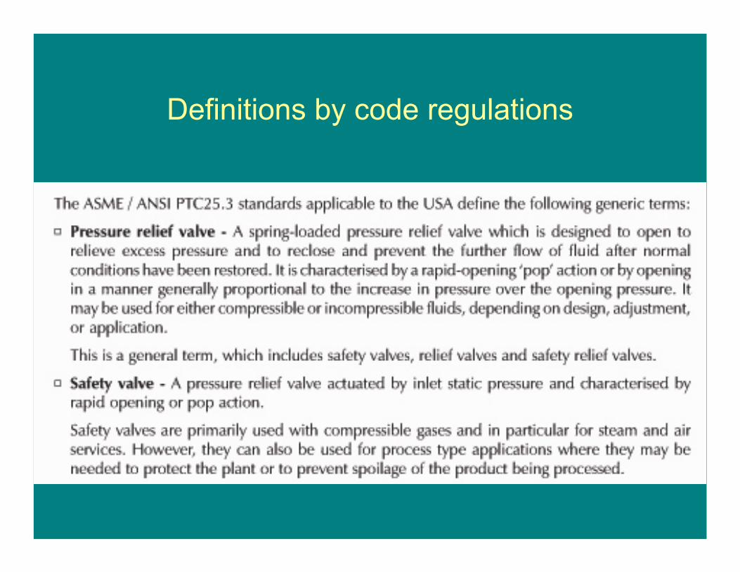
Definitions by code regulations
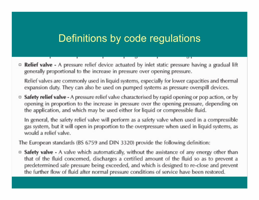
Definitions by code regulations
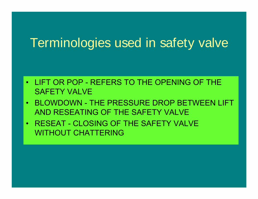
Terminologies used in safety valve
• LIFT OR POP - REFERS TO THE OPENING OF THE SAFETY VALVE
• BLOWDOWN - THE PRESSURE DROP BETWEEN LIFT AND RESEATING OF THE SAFETY VALVE
• RESEAT - CLOSING OF THE SAFETY VALVE WITHOUT CHATTERING
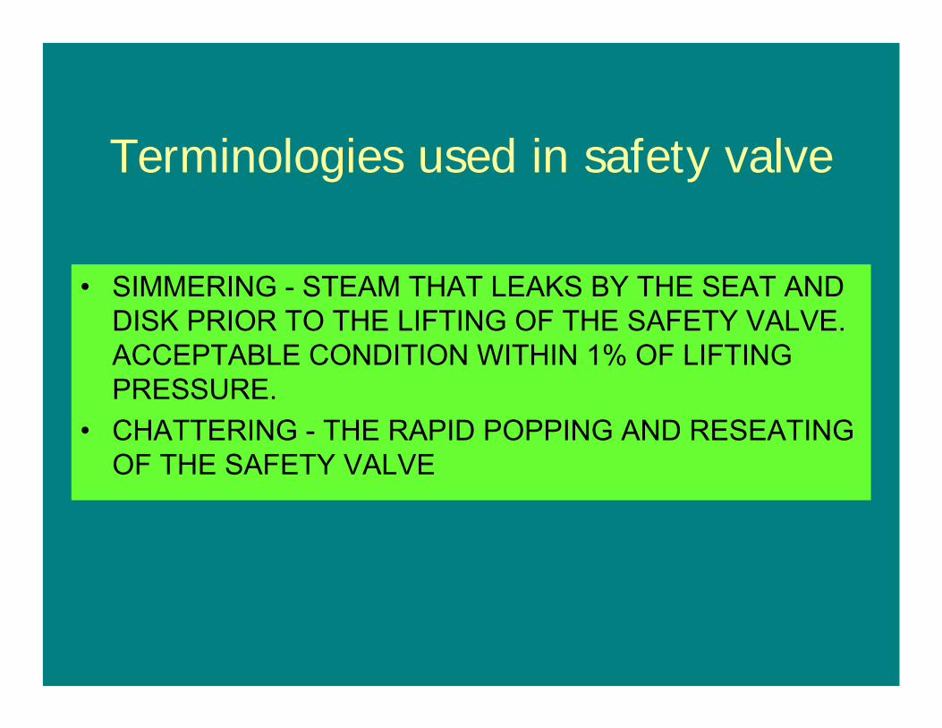
• SIMMERING - STEAM THAT LEAKS BY THE SEAT AND DISK PRIOR TO THE LIFTING OF THE SAFETY VALVE. ACCEPTABLE CONDITION WITHIN 1% OF LIFTING PRESSURE.
• CHATTERING - THE RAPID POPPING AND RESEATING OF THE SAFETY VALVE
Terminologies used in safety valve
• GAG - A MECHANICAL DEVICE PLACED ON THE SAFETY TO PREVENT THE SAFETY FROM LIFTING DURING TESTING AND BOILER HYDROSTATIC TESTS
Terminologies used in safety valve
• MAWP• Design pressure• Operating
pressure• Set pressure• Overpressure• Accumulation• Blowdown
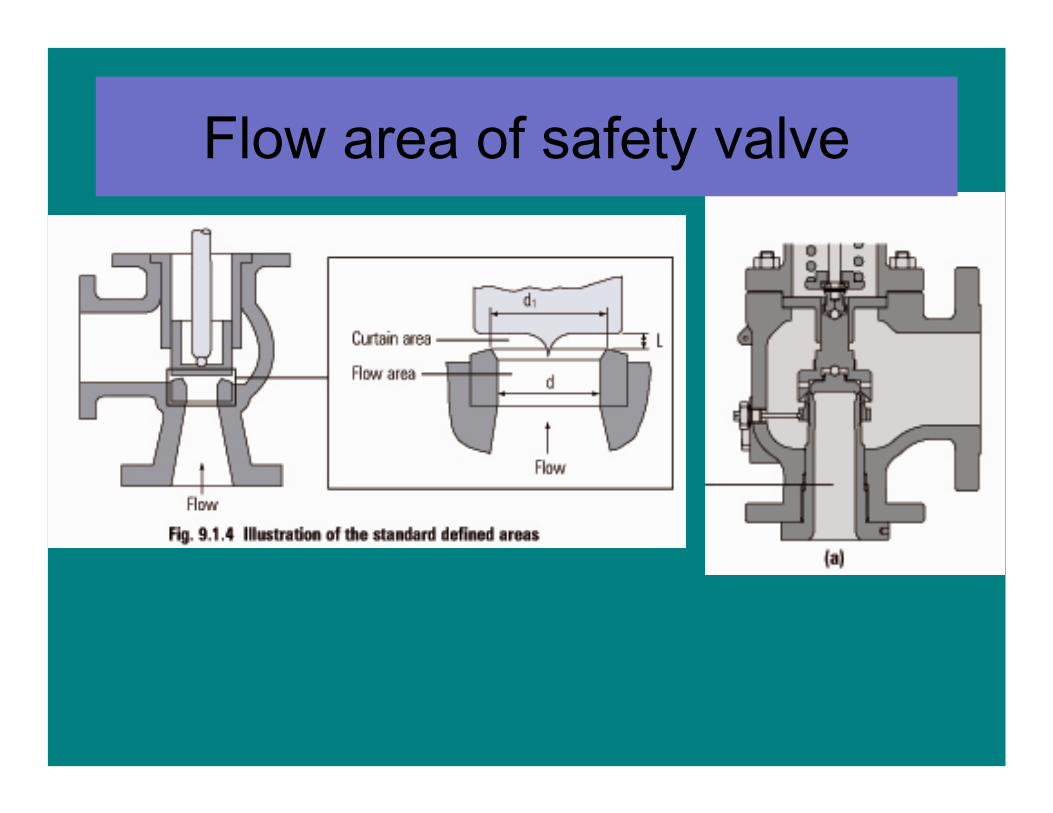
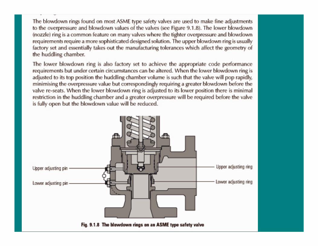
Flow area of safety valve
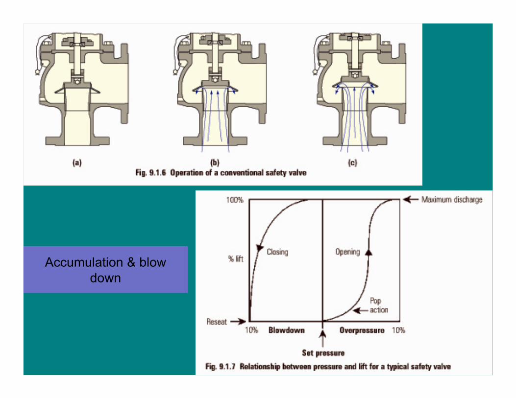
Accumulation & blow down
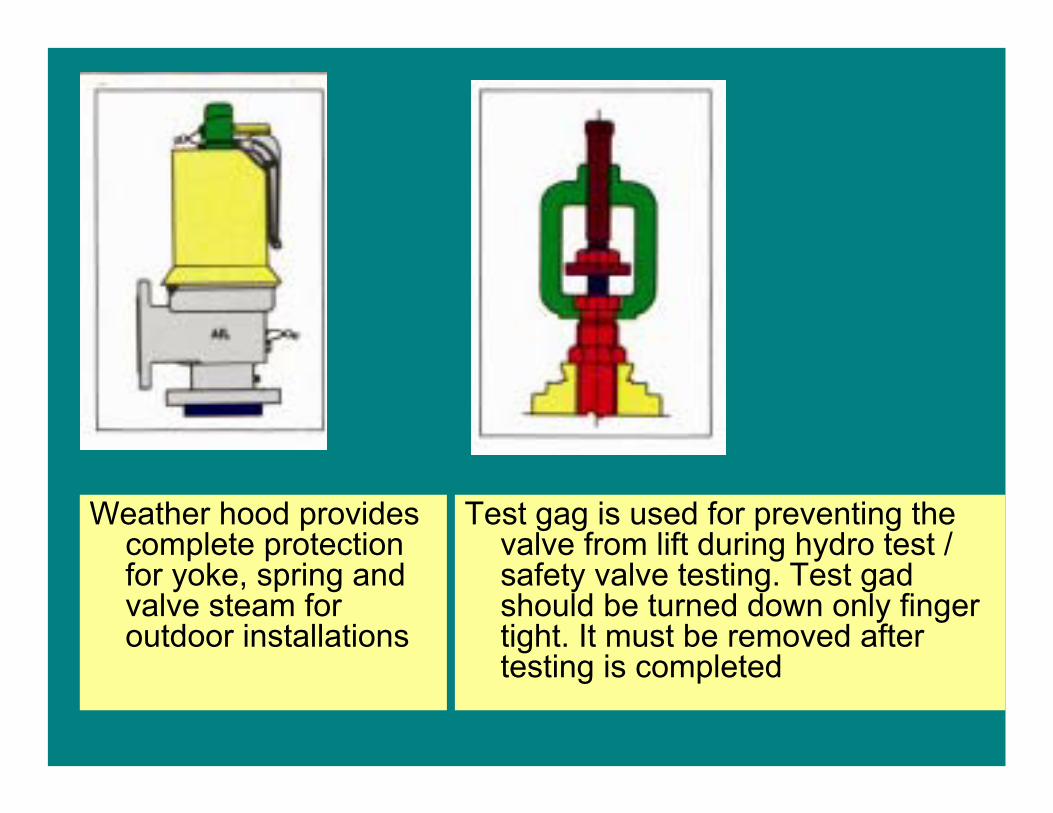
Weather hood provides complete protection for yoke, spring and valve steam for outdoor installations
Test gag is used for preventing the valve from lift during hydro test / safety valve testing. Test gad should be turned down only finger tight. It must be removed after testing is completed
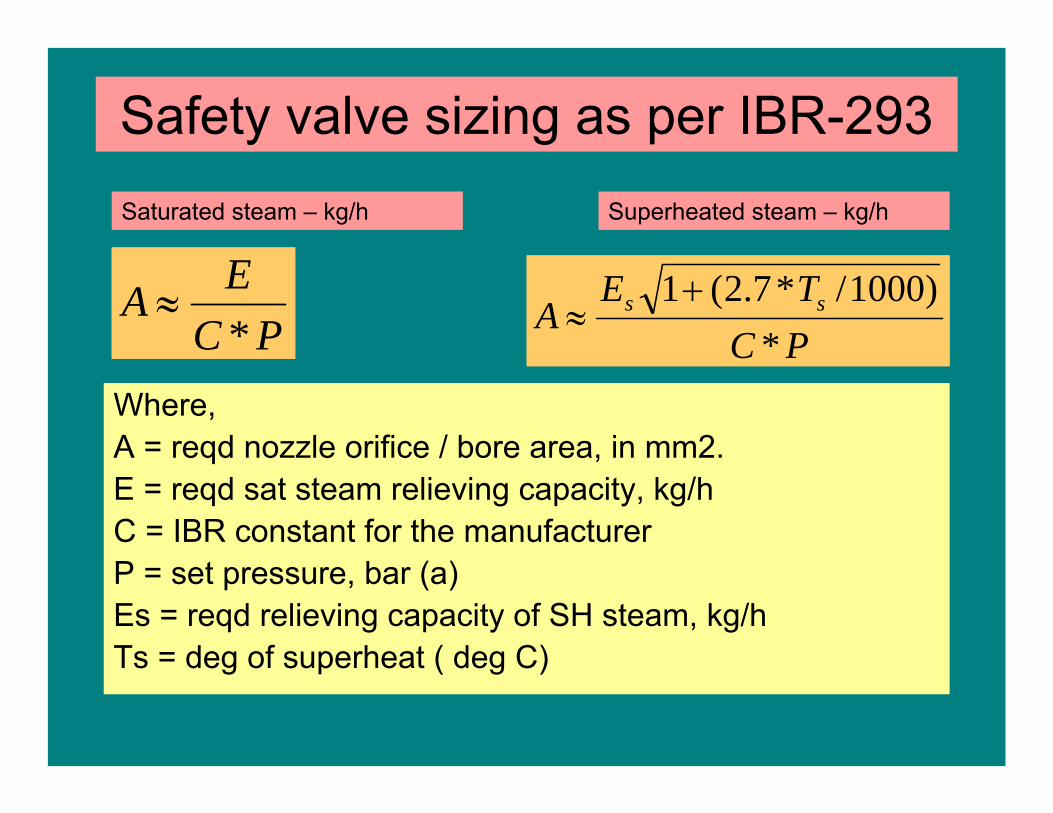
Safety valve sizing as per IBR-293
Where,A = reqd nozzle orifice / bore area, in mm2.E = reqd sat steam relieving capacity, kg/hC = IBR constant for the manufacturerP = set pressure, bar (a)Es = reqd relieving capacity of SH steam, kg/hTs = deg of superheat ( deg C)
PCTE
A ss
*)1000/*7.2(1+
≈
Saturated steam – kg/h
PCEA*
≈
Superheated steam – kg/h
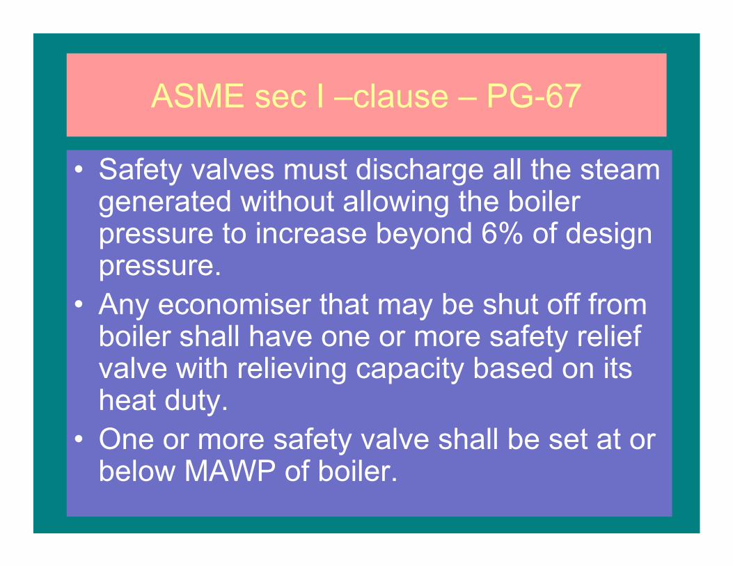
ASME sec I –clause – PG-67
• Safety valves must discharge all the steam generated without allowing the boiler pressure to increase beyond 6% of design pressure.
• Any economiser that may be shut off from boiler shall have one or more safety relief valve with relieving capacity based on its heat duty.
• One or more safety valve shall be set at or below MAWP of boiler.
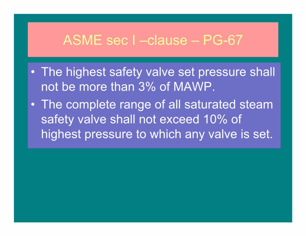
ASME sec I –clause – PG-67
• The highest safety valve set pressure shall not be more than 3% of MAWP.
• The complete range of all saturated steam safety valve shall not exceed 10% of highest pressure to which any valve is set.
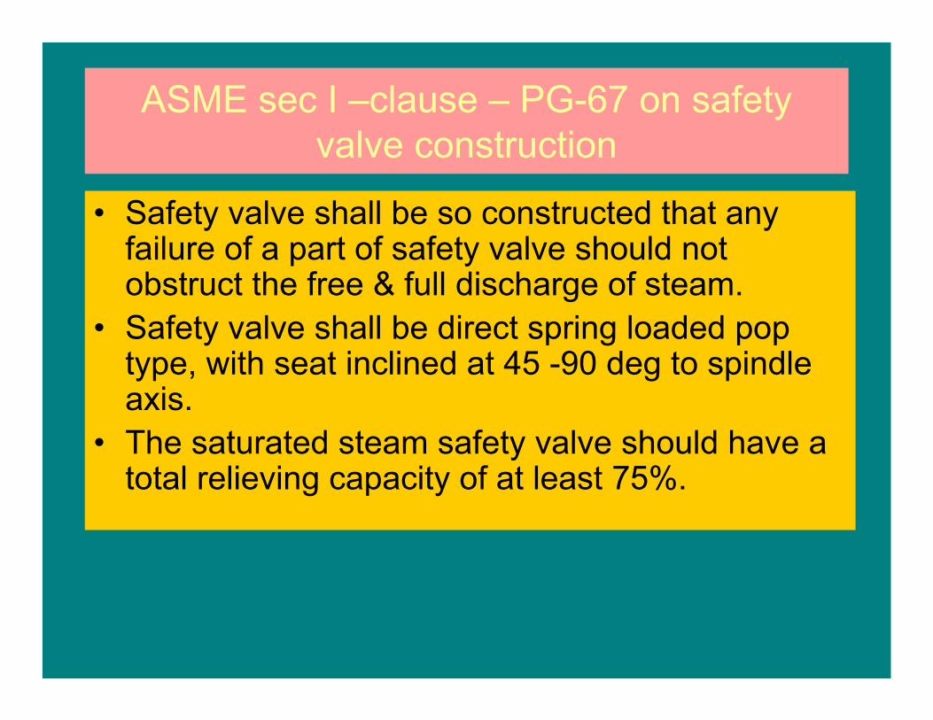
ASME sec I –clause – PG-67 on safety valve construction
• Safety valve shall be so constructed that any failure of a part of safety valve should not obstruct the free & full discharge of steam.
• Safety valve shall be direct spring loaded pop type, with seat inclined at 45 -90 deg to spindle axis.
• The saturated steam safety valve should have a total relieving capacity of at least 75%.

ASME sec I –clause – PG-67 on safety valve construction
• When two different size valves are used at drum, the smaller safety valve shall at least equal to 50% of relieving capacity of bigger valve.
• Safety valve shall be designed to vent the steam without chattering with a minimum blow down of 2 psi or 2% of set pressure whichever is greater.
• Safety valves shall lift fully at a pressure not exceeding 3% of set pressure.
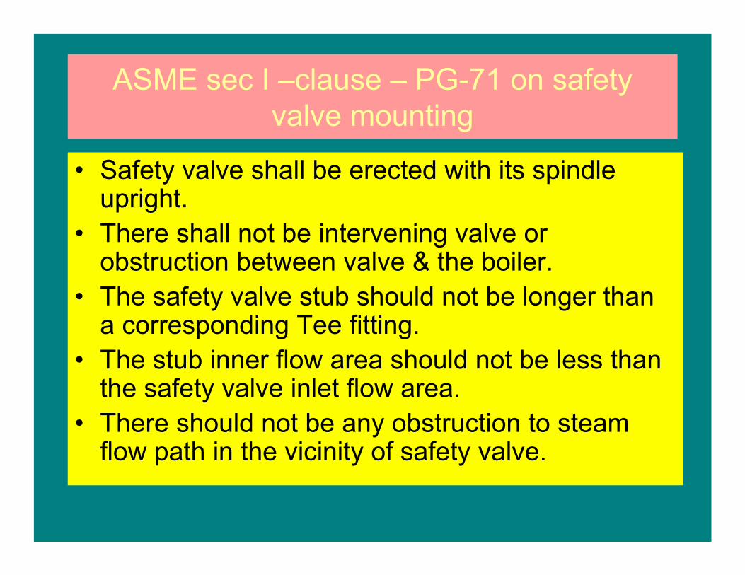
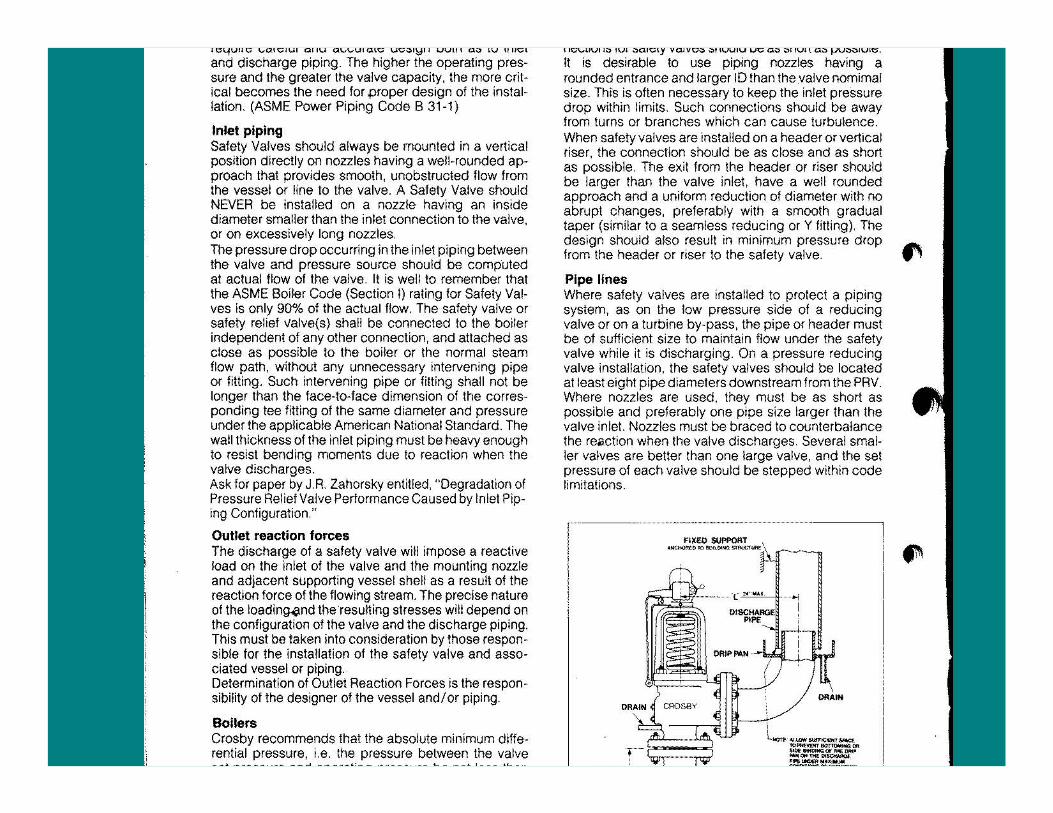
ASME sec I –clause – PG-71 on safety valve mounting
• Safety valve shall be erected with its spindle upright.
• There shall not be intervening valve or obstruction between valve & the boiler.
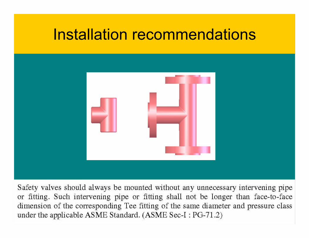
• The safety valve stub should not be longer than a corresponding Tee fitting.
• The stub inner flow area should not be less than the safety valve inlet flow area.
• There should not be any obstruction to steam flow path in the vicinity of safety valve.
ASME sec I –clause – PG-71 on safety valve mounting
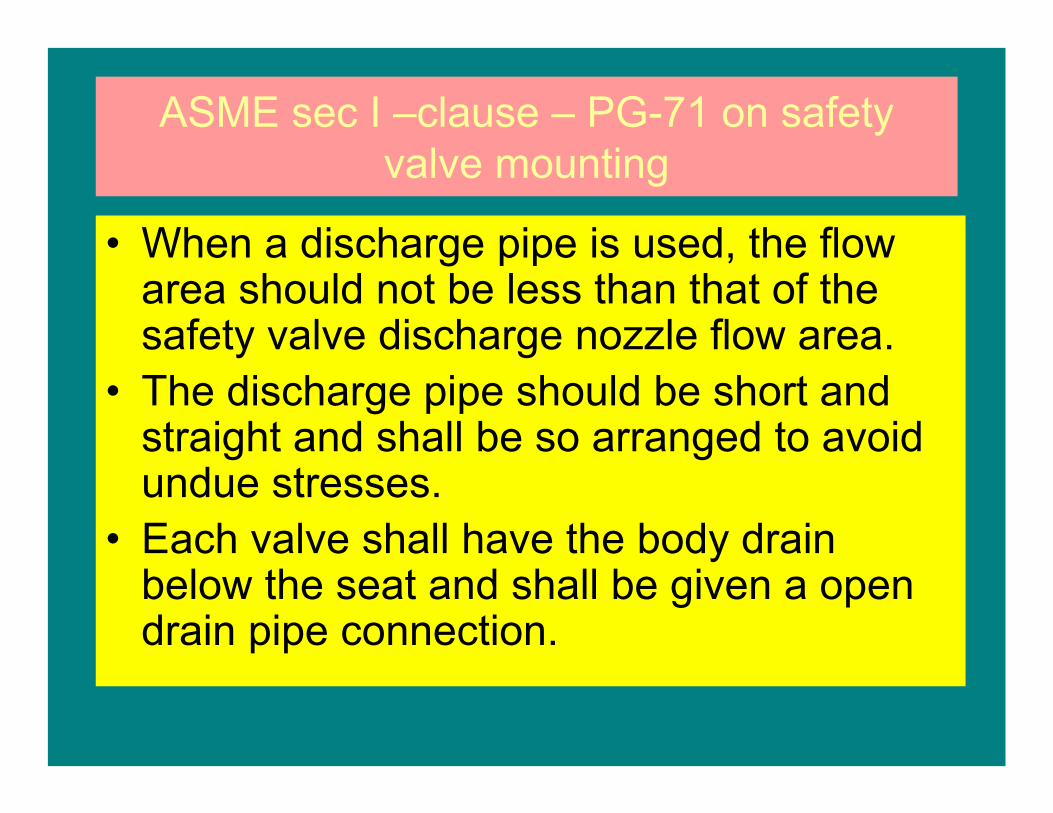
• When a discharge pipe is used, the flow area should not be less than that of the safety valve discharge nozzle flow area.
• The discharge pipe should be short and straight and shall be so arranged to avoid undue stresses.
• Each valve shall have the body drain below the seat and shall be given a open drain pipe connection.
ASME sec I –clause – PG-71 on safety valve mounting
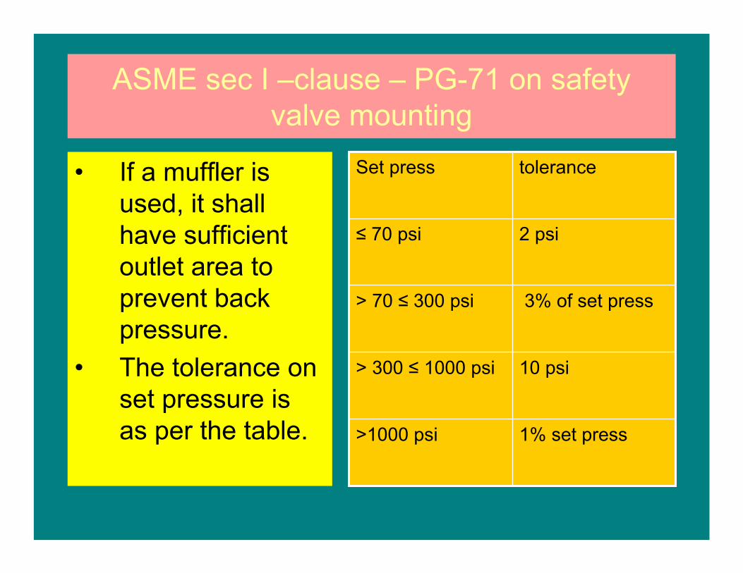
• If a muffler is used, it shall have sufficient outlet area to prevent back pressure.
• The tolerance on set pressure is as per the table. 1% set press>1000 psi
10 psi> 300 ≤ 1000 psi
3% of set press> 70 ≤ 300 psi
2 psi≤ 70 psi
toleranceSet press
ASME sec I –clause – PG-71 on safety valve mounting
• The spring in a safety valve shall bot be reset for any pressure more than 5% above or below that for which it marked.
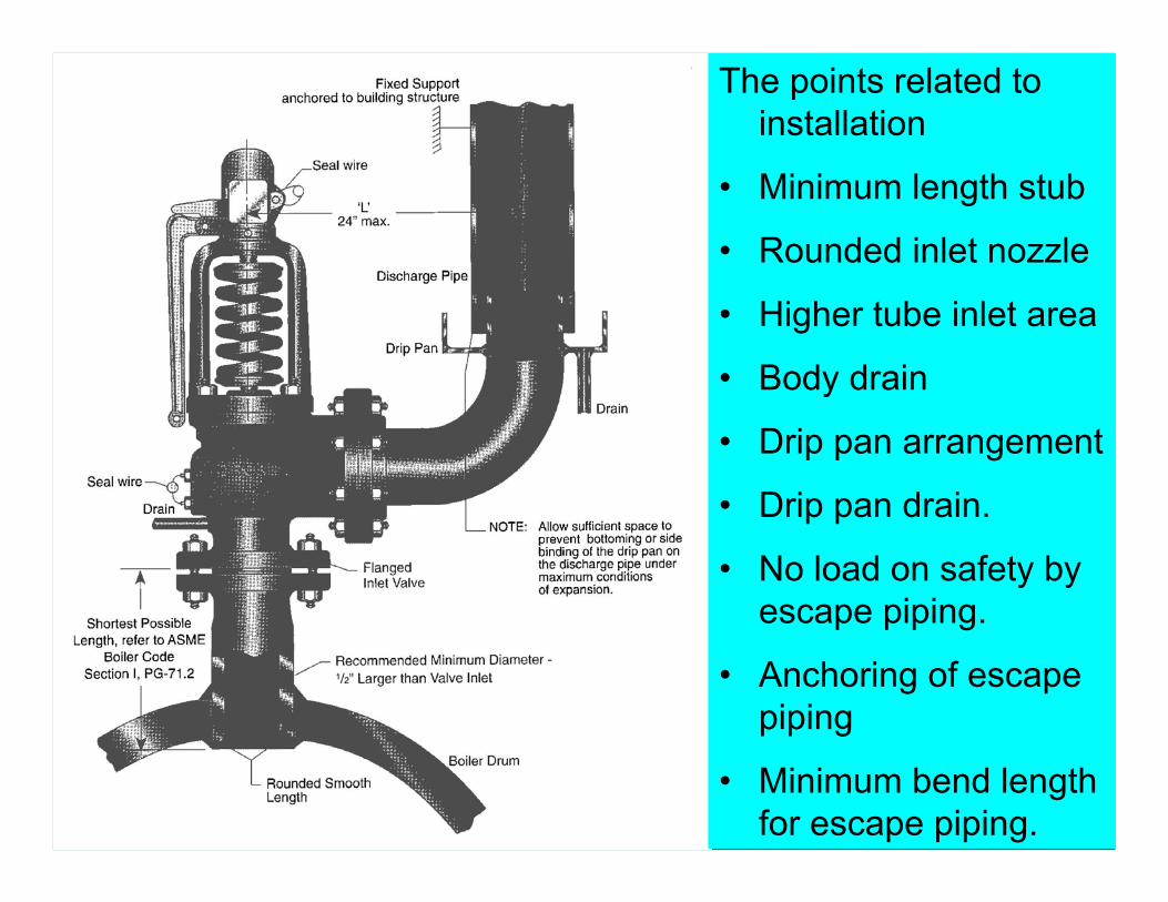
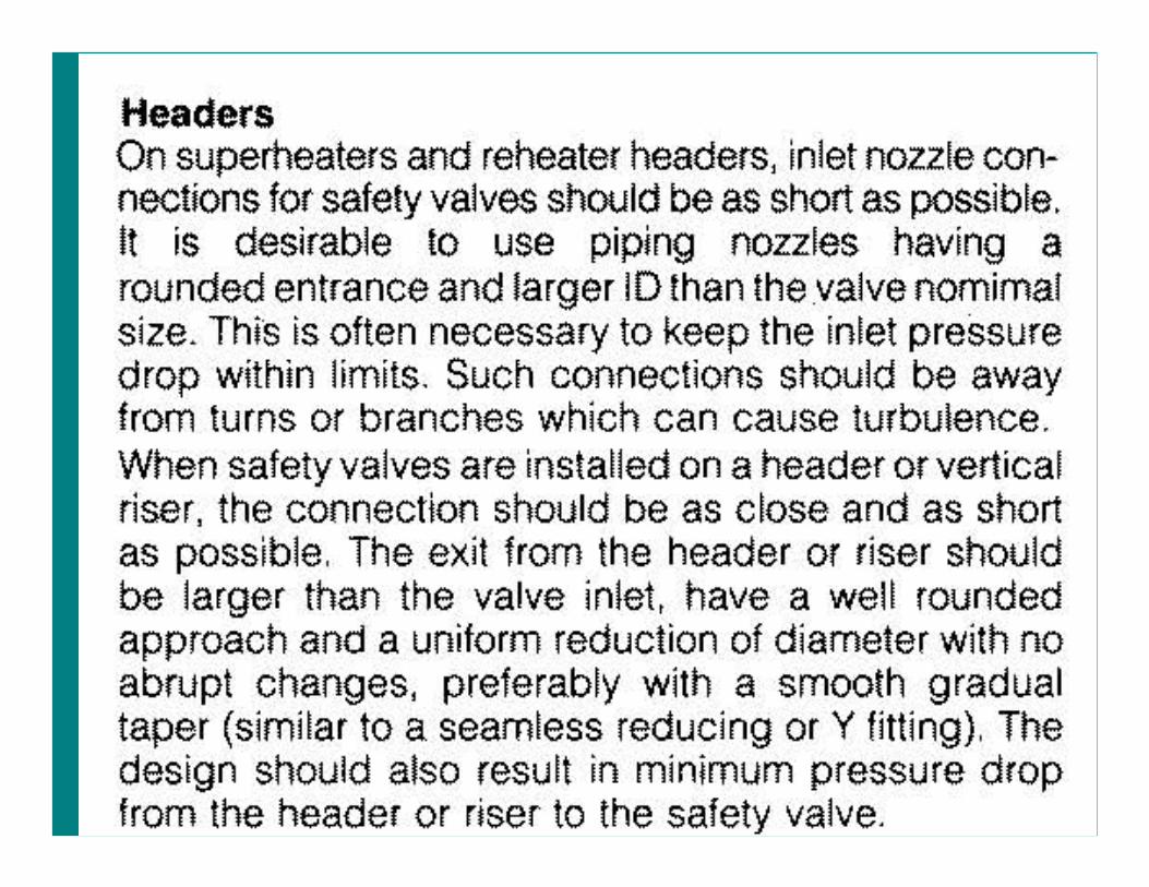
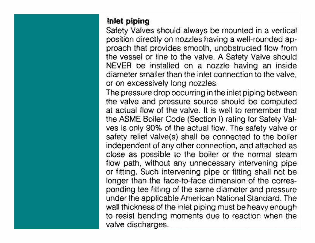
The points related to installation
• Minimum length stub
• Rounded inlet nozzle
• Higher tube inlet area
• Body drain
• Drip pan arrangement
• Drip pan drain.
• No load on safety by escape piping.
• Anchoring of escape piping
• Minimum bend length for escape piping.
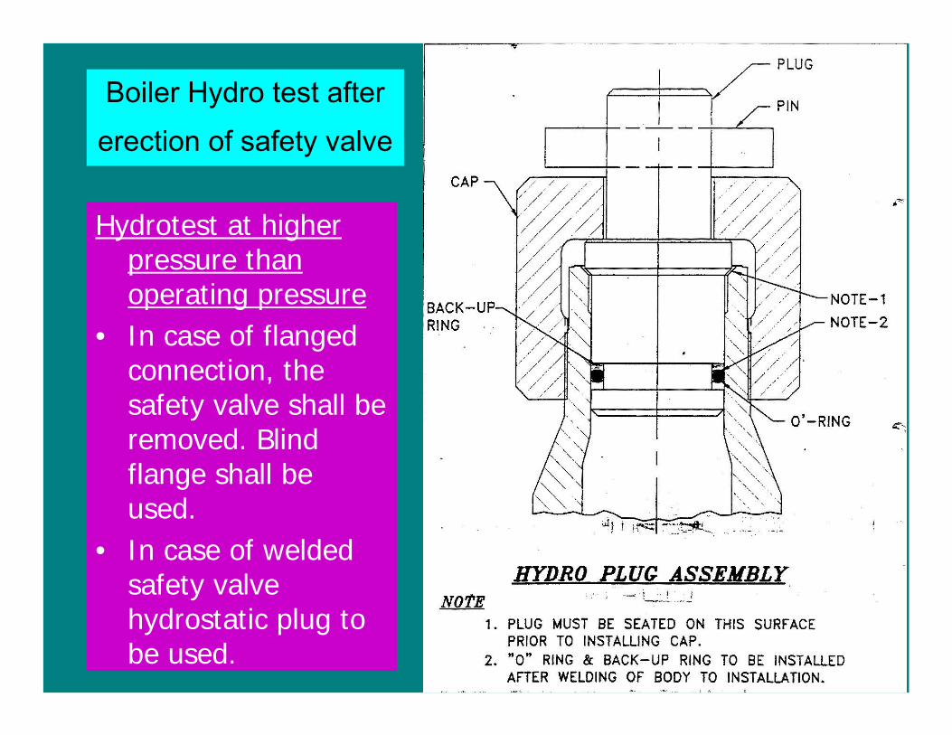
Boiler Hydro test after
erection of safety valve
Hydrotest at higher pressure than operating pressure
• In case of flanged connection, the safety valve shall be removed. Blind flange shall be used.
• In case of welded safety valve hydrostatic plug to be used.
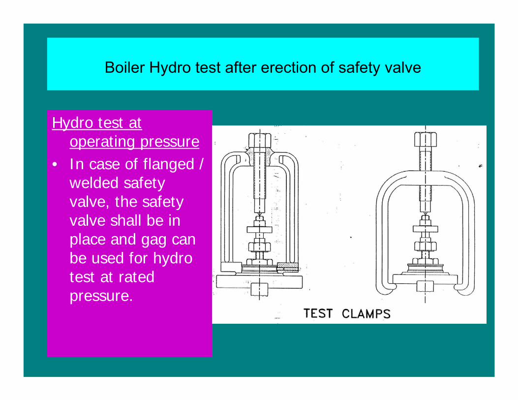
Boiler Hydro test after erection of safety valve
Hydro test at operating pressure
• In case of flanged / welded safety valve, the safety valve shall be in place and gag can be used for hydro test at rated pressure.
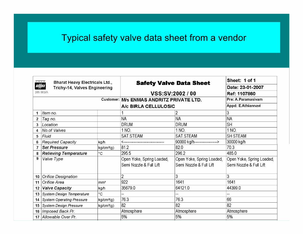
Typical safety valve data sheet from a vendor
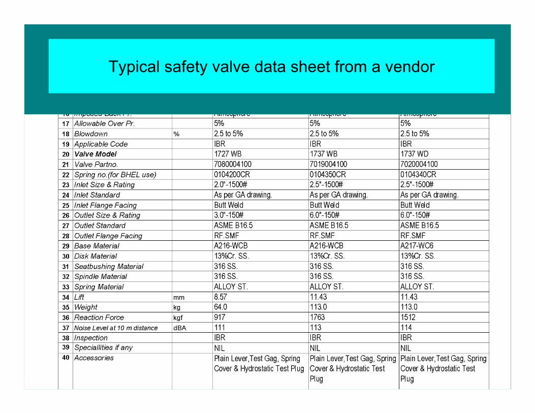
Typical safety valve data sheet from a vendor
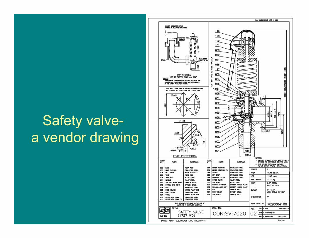
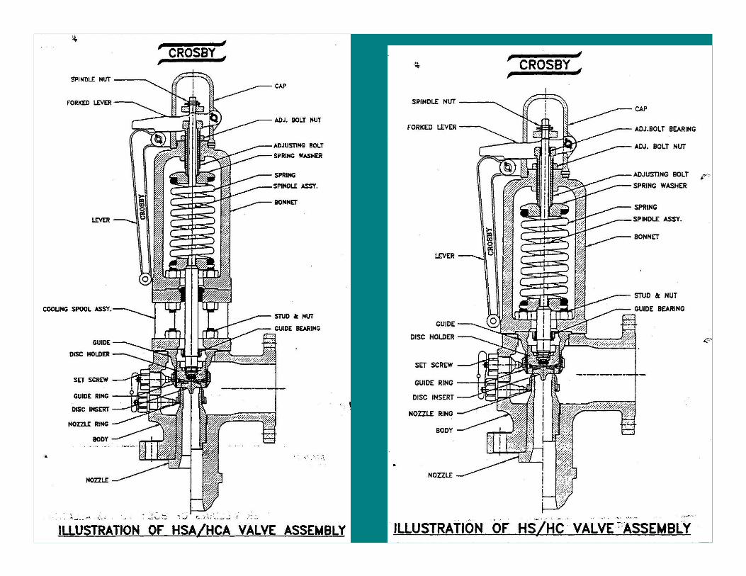
Safety valve-a vendor drawing
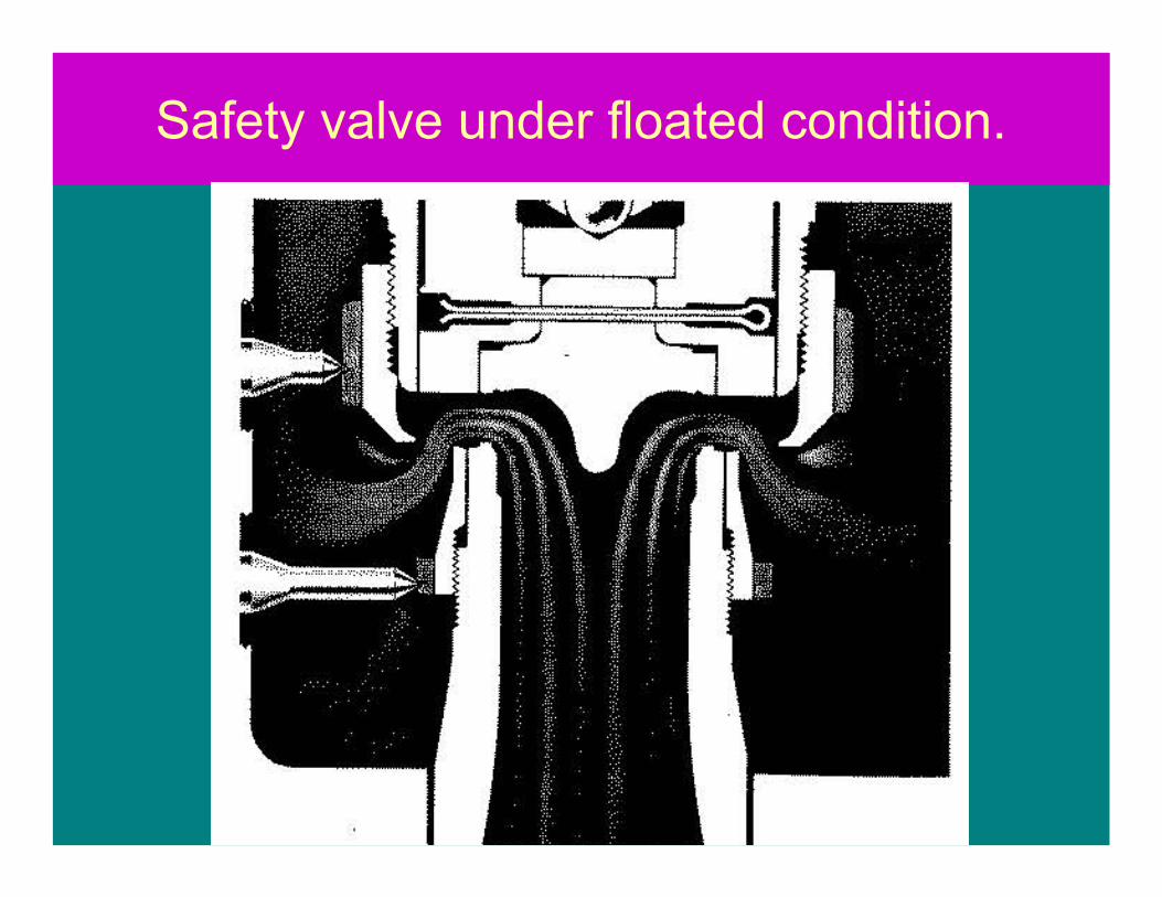
Safety valve under floated condition.
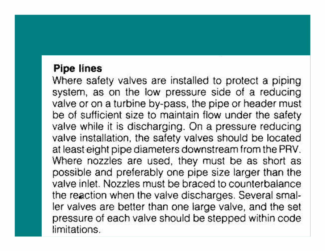

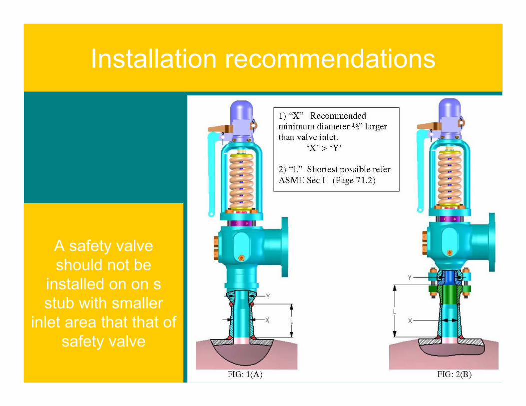
Installation recommendations
A safety valve should not be
installed on on s stub with smaller
inlet area that that of safety valve
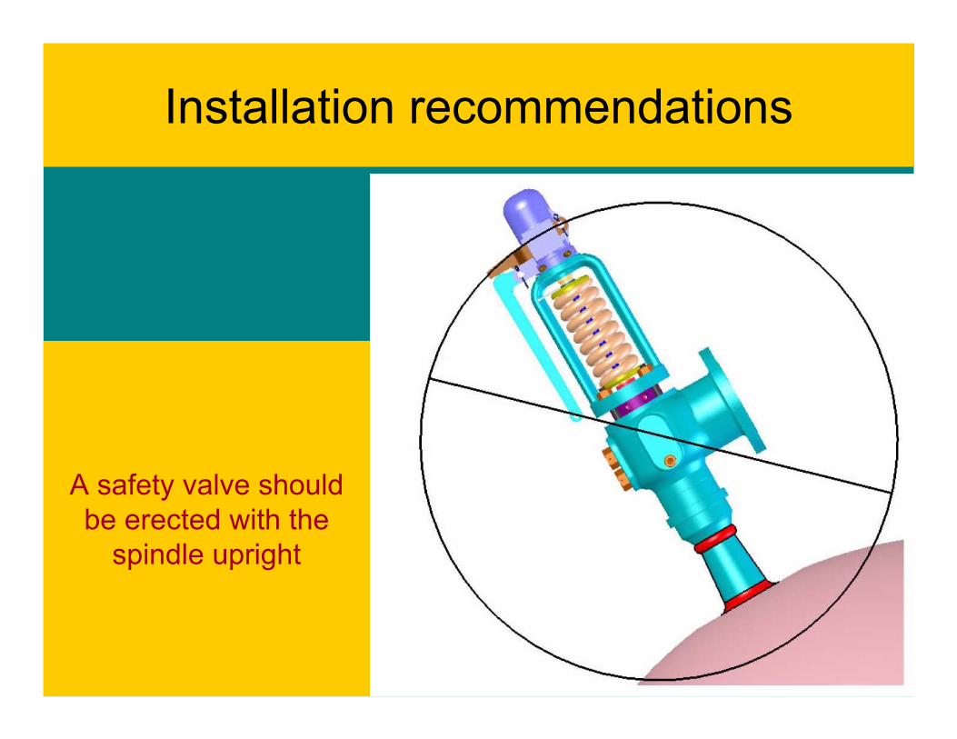
Installation recommendations
A safety valve should be erected with the
spindle upright
Installation recommendations
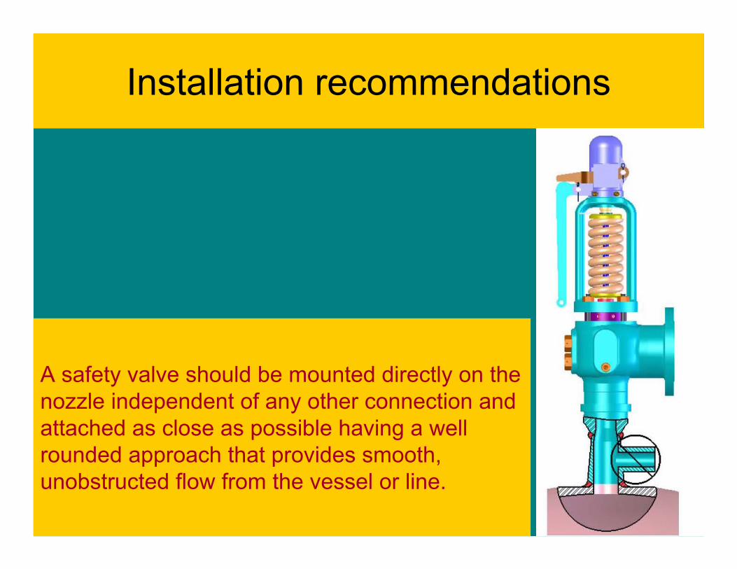
A safety valve should be mounted directly on the nozzle independent of any other connection and attached as close as possible having a well rounded approach that provides smooth, unobstructed flow from the vessel or line.
Installation recommendations
Installation recommendations
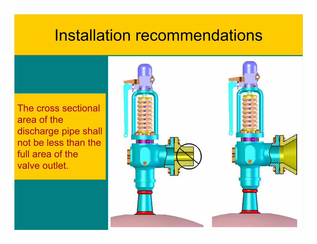
The cross sectional area of the discharge pipe shall not be less than the full area of the valve outlet.
Installation recommendations
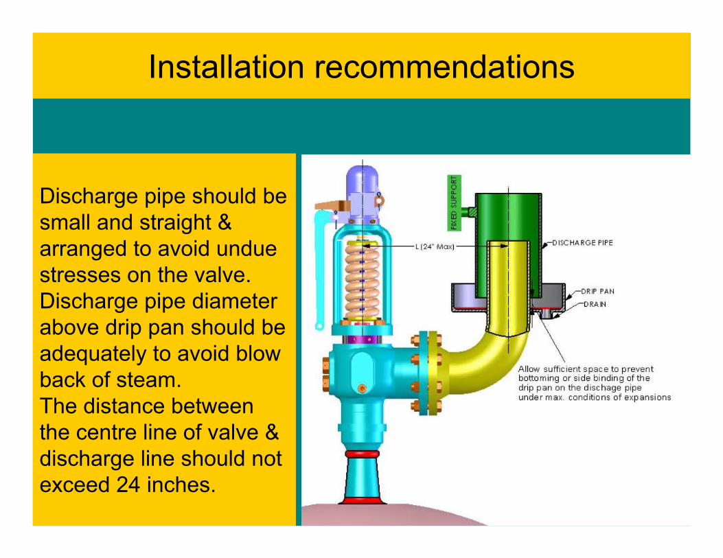
Discharge pipe should be small and straight & arranged to avoid undue stresses on the valve. Discharge pipe diameter above drip pan should be adequately to avoid blow back of steam.The distance between the centre line of valve & discharge line should not exceed 24 inches.

Installation recommendations
The cross sectional area of the discharge pipe shall not be less than the full area of the valve outlet.

Installation recommendations
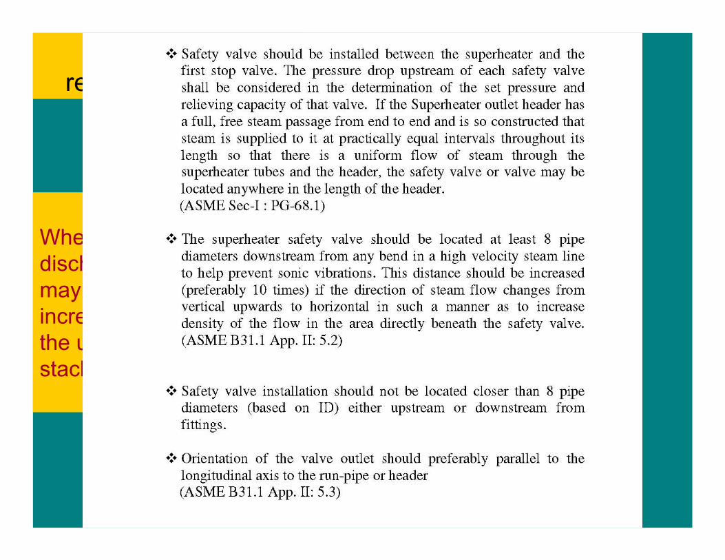
When the length of discharge pipe is long, it may be necessary to increase the diameter in the upper part of the stack.
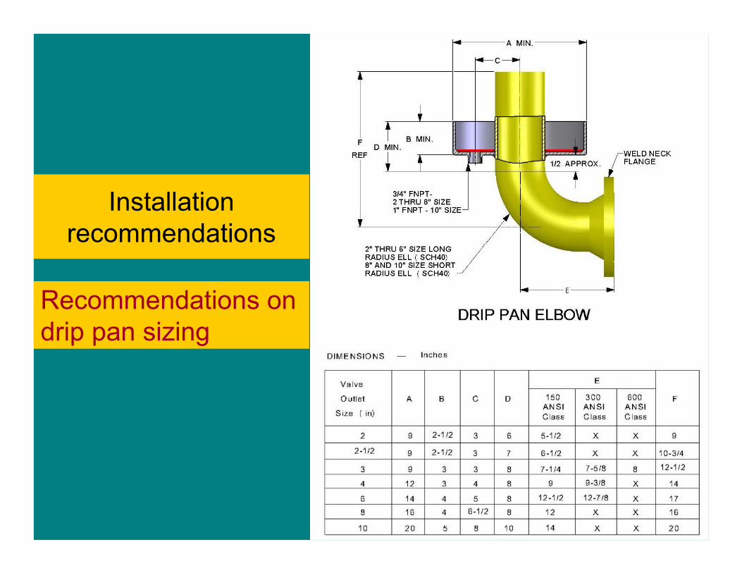
Installation recommendations
Recommendations on drip pan sizing
Installation recommendations
When the length of discharge pipe is long, it may be necessary to increase the diameter in the upper part of the stack.

PRESSURE %PRESSURE %
103103
100100100
959595
939393
MAWPMAWPMAWP
ALLOWABLEOVERPRESSUREALLOWABLEALLOWABLEOVERPRESSUREOVERPRESSURE
TYPICAL SETPRESSURETYPICAL SETPRESSURE
TYPICAL OPERATINGPRESSURE(“THE MONEY MAKER”)
TYPICAL OPERATINGPRESSURE(“THE MONEY MAKER”)
SET PRESSURETOLERANCE
SET PRESSURETOLERANCE
TYPICAL RESEAT
PRESSURE
TYPICAL RESEAT
PRESSURE
BLOWDOWN,% OF SET
BLOWDOWN,% OF SET
ASME Section 1 Valves- pressure relations


