end of the mount, and will be supplied by General Dynamics. Above it is the support ring for “M2,” the secondary mirror, which in turn is suspended over the primary by a support cage and four tensioning vanes that attach to the support ring. We will fabricate M2, now in its advanced design stage. The Active Optics We noted above that M1 is “floppy.” Not to the point that you could see it bend, of course; that would be a disaster! But the mirror can flex enough to destroy the images. Thus, the DCT will be equipped with a sensor that will constantly sample the image quality across the mirror, sending instructions to the actuators that make them push against the mirror to maintain its shape as the DCT moves around. The Software All these major components are controlled by computer programs. Separate software systems will control the mount, the active optics, the dome environment, the telescope itself, and the instru- ments. All these systems must communicate flawlessly; the “blue screen of death” can ruin your entire night! Presently, we are in the advanced stages of creating the software architecture. The code to make all this happen will be both contracted out and written in- house. As you might imagine, these are only the most cursory descriptions of a monstrously complex facility. However, if you keep these six subsystems in mind, you’ll have a basic blueprint for reading more detailed descriptions that may appear in the Observer or on our blog. It’s a lot to get done by the end of 2010, but it is exciting to have all these systems moving steadily along and to see this extraordinary facility taking shape. We are glad you are along for the ride with us! DCT Component Walk-through DCT Autoguider and Wavefront Sensor DCT First Light Challenge Navajo Hopi Astronomy Outreach Program In Memoriam: Frances McAllister O U T R E A C H S C I E N C E F E A T U R E S A DCT Component Walk-through By Jeff Hall In recent months, you may have seen letters, blog posts, or other mentions from Lowell that all components of the DCT are “actively being worked.” As with any complex engineer- ing project, the DCT comprises a number of components that must function correctly on their own, as well as in relation to all the others. As of fall 2008, several of these components, such as the primary mirror, are being manufactured. The others are approaching their critical design reviews (CDRs), which are the final steps before construction begins. You’ll be read- ing a lot about DCT in upcoming years, so here’s a short glossary of the main components. The Dome This is the rotating part of the building enclosing the DCT. The ventilation and geometry of the dome are critical to effective operation of the telescope. We have abandoned the traditional hemispherical shape in favor of a more angular shape; this makes the dome lower, increases operating room inside, and lowers construction costs. The Mount We have contracted with General Dynamics to build the mount, and their computer-aided rendering of its appearance is shown at right. The mount will have its CDR in early 2009, and will be assembled at the Happy Jack site in 2010. It encompasses the entire structure that supports the two mirrors. The pink boxes in the picture show the volumes that will be available for mounting instru- ments to the DCT. The Primary Mirror Also known as “M1,” the primary mirror will live in a support cell at the back end of the cylindrical telescope struc- ture. Because it is thin and “floppy,” it will be supported by an array of 120 devices called actuators mounted to its back surface, with additional supports around its perimeter. It will also be equipped with a cooling system to keep its tempera- ture as close to the ambient temperature as possible. The Secondary Mirror Look closely at the top end of the telescope in the CAD rendering, and you’ll see two rings. One of those is the top 1 2 3 3 2 Computer-aided rendering of the Discovery Channel Telescope mount. P E R C Y’ S J O U R N A L
Transcript
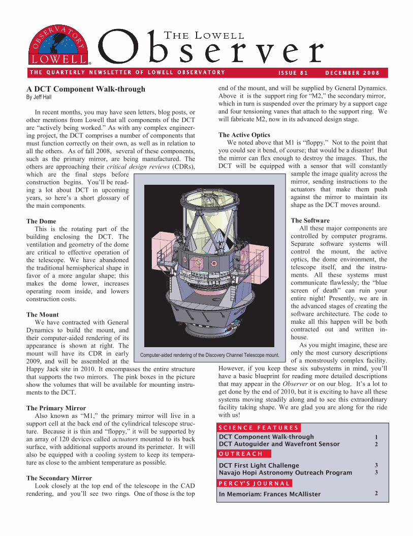
end of the mount, and will be supplied by General Dynamics. Above it is the support ring for “M2,” the secondary mirror, which in turn is suspended over the primary by a support cage and four tensioning vanes that attach to the support ring. We will fabricate M2, now in its advanced design stage.
The Active Optics We noted above that M1 is “floppy.” Not to the point that you could see it bend, of course; that would be a disaster! But the mirror can flex enough to destroy the images. Thus, the DCT will be equipped with a sensor that will constantly
sample the image quality across the mirror, sending instructions to the actuators that make them push against the mirror to maintain its shape as the DCT moves around.
The Software All these major components are controlled by computer programs. Separate software systems will control the mount, the active optics, the dome environment, the telescope itself, and the instru-ments. All these systems must communicate flawlessly; the “blue screen of death” can ruin your entire night! Presently, we are in the advanced stages of creating the software architecture. The code to make all this happen will be both contracted out and written in-house. As you might imagine, these are only the most cursory descriptions of a monstrously complex facility.
However, if you keep these six subsystems in mind, you’ll have a basic blueprint for reading more detailed descriptions that may appear in the Observer or on our blog. It’s a lot to get done by the end of 2010, but it is exciting to have all these systems moving steadily along and to see this extraordinary facility taking shape. We are glad you are along for the ride with us!
DCT Component Walk-through DCT Autoguider and Wavefront Sensor DCT First Light Challenge Navajo Hopi Astronomy Outreach Program In Memoriam: Frances McAllister
O U T R E A C H
S C I E N C E F E A T U R E S
A DCT Component Walk-through By Jeff Hall
In recent months, you may have seen letters, blog posts, or other mentions from Lowell that all components of the DCT are “actively being worked.” As with any complex engineer-ing project, the DCT comprises a number of components that must function correctly on their own, as well as in relation to all the others. As of fall 2008, several of these components, such as the primary mirror, are being manufactured. The others are approaching their critical design reviews (CDRs), which are the final steps before construction begins. You’ll be read-ing a lot about DCT in upcoming years, so here’s a short glossary of the main components.
The Dome
This is the rotating part of the building enclosing the DCT. The ventilation and geometry of the dome are critical to effective operation of the telescope. We have abandoned the traditional hemispherical shape in favor of a more angular shape; this makes the dome lower, increases operating room inside, and lowers construction costs.
The Mount
We have contracted with General Dynamics to build the mount, and their computer-aided rendering of its appearance is shown at right. The mount will have its CDR in early 2009, and will be assembled at the Happy Jack site in 2010. It encompasses the entire structure that supports the two mirrors. The pink boxes in the picture show the volumes that will be available for mounting instru-ments to the DCT.
The Primary Mirror
Also known as “M1,” the primary mirror will live in a support cell at the back end of the cylindrical telescope struc-ture. Because it is thin and “floppy,” it will be supported by an array of 120 devices called actuators mounted to its back surface, with additional supports around its perimeter. It will also be equipped with a cooling system to keep its tempera-ture as close to the ambient temperature as possible.
The Secondary Mirror Look closely at the top end of the telescope in the CAD rendering, and you’ll see two rings. One of those is the top
1
2
3
3
2
Computer-aided rendering of the Discovery Channel Telescope mount.
P E R C Y’ S J O U R N A L
The DCT will be guided with sampling of the guide star position at 5 Hz with one GWAVES stage/camera assembly, and the wavefront sampled in parallel at 30 s intervals with the other assembly. Other DCT instruments, including the DeVeny Spectrograph and NIHTS (Near Infrared High Throughput Spectrograph) will be mounted at side ports on the cube, where the telescope beam will be folded by a mirror mounted on the telescope axis. During folded instrument operations, the GWAVES cameras will analyze stars located in a field annulus surrounding the fold mirror. GWAVES will also be essential for early testing of the completed DCT, char-acterizing the performance of the mount and optics from first light by the end of 2010 through commissioning of the tele-scope into regular scientific operations.
DECEMBER 2008 THE LOWELL OBSERVER 2
The Discovery Channel Telescope will track and observe both sidereal objects (stars and galaxies) and non-sidereal objects (planets, moons, comets and KBO’s moving with respect to the stars) with very high precision. Still, in order to extract the largest possible signal-to-noise from scientific targets with the highly sensitive cameras within imaging and spectroscopic instruments, it is necessary to guide the DCT with small precision offsets by use of an auxiliary autoguider that locks onto the signal of stars within the target field. And, to deliver tightly focused images by the optics of the DCT, it is also necessary to measure the wavefront produced by the meniscus primary mirror in concert with alignment of the primary and secondary mirrors. These optical quality meas-urements will be translated to continuous adjustments of the 120 primary mirror actuated supports, and tip and tilt of the secondary mirror to maintain collimation, as the telescope elevation pointing changes. Both of these essential opera-tional functions will be served by GWAVES, the DCT autoguider and wavefront sensor under development by the Lowell Instrument Group.
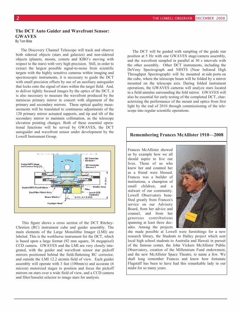
This figure shows a cross section of the DCT Ritchey-Chretien (RC) instrument cube and guider assembly. The main elements of the Large Monolithic Imager (LMI) are labeled. This is the workhorse instrument for the DCT, which is based upon a large format (92 mm square, 36 megapixel) CCD camera. GWAVES and the LMI are very closely inte-grated, with the guider and wavefront sensor star pickoff mirrors positioned behind the field-flattening RC corrector, and outside the LMI 12.2 arcmin field of view. Each guider assembly will operate with 3 fast (100mm/s) and accurate (6 micron) motorized stages to position and focus the pickoff mirrors on stars over a wide field of view, and a CCD camera and filter/lenselet selector to image stars for analysis.
The DCT Auto Guider and Wavefront Sensor:
GWAVES By Tom Bida
Frances McAllister showed us by example how we all should aspire to live our lives. Those of us who knew her and counted her as a friend were blessed. Frances was a builder of institutions, a champion of small children, and a stalwart of our community. Lowell Observatory bene-fited greatly from Frances's service on our Advisory Board, from her advice and counsel, and from her generous contributions spanning at least three dec-ades. Among the projects she made possible at Lowell were furnishings for a new research library, the Students to Halley project which sent local high school students to Australia and Hawaii in pursuit of the famous comet, the John Vickers McAllister Public Observatory, creation of the Millennium Fund endowment, and the new McAllister Space Theatre, to name a few. We shall long remember Frances and know how fortunate Flagstaff has been to have had this remarkable lady in our midst for so many years.
Remembering Frances McAllister 1910—2008
DECEMBER 2008 3
Lowell Observatory is involved in different aspects of outreach to the local communities here in Northern Arizona. One program involves the Navajo and Hopi Nations. Drs. Deidre Hunter and Amanda Bosh started the Navajo-Hopi Astronomy Outreach Program in 1996. Lowell astronomers have an opportunity to partner with a fifth through eighth grade teacher approximately once a month at these often remote schools. A goal is to encourage the teachers to become comfortable providing astronomy instruction in their class-rooms. A slew of activities are offered that are as much fun as they are educational. Astronomical topics include the phases of the moon, the reason for the seasons, our Solar System, stars, constellations, the Milky Way galaxy, and cosmology. All of these topics are pertinent to Arizona teach-ing standards and are included in a workbook which is provided to each teacher. To kick off this year’s partnership, Lowell Observatory hosted a teacher workshop in September where past and present outreach participants were invited to join the five Lowell astronomers who are involved in this year’s outreach program. Also participating was Lowell Advisory Board member Vera Rubin, who gave her insights into the nature of science and acted as photographer during the sessions. The day and a half workshop was an opportunity for Lowell astronomers to demonstrate 10 activities to the teachers primarily focused on the basics of astronomy. By performing the activities themselves, the teachers were able to identify and anticipate their students’ misconceptions and also make cultural connections. At the end of the practicum, each teacher was given two large bins containing all of the materials necessary to demonstrate each activity in their own classrooms. The workshop was a great success, with 14 teachers participating!
The Discovery Channel First Light Challenge By Rusty Tweed
In 1997, Lowell Observatory began planning a telescope to meet the needs of the next generation of Lowell astronomers and their collaborators in their ongoing quest to push back the frontiers of astronomical knowledge. Ten years later, we are in the home stretch. With first light scheduled by the end of 2010, the completion of the Discovery Channel Telescope is imminent. The DCT is the largest undertaking in Lowell’s history and is essential for the Observatory’s continued suc-cess. Now that completion is in sight, we are preparing to build two important elements of the DCT that are necessary for full operation. Lowell Observatory has been presented with a wonderful challenge to build the autoguider/wavefront sensor for the telescope (see article on previous page), as well as lodging quarters for DCT astronomers and operators. In an extraordi-nary gesture, two families have stepped forward to lead the way: Lowell Advisory Board member John Giovale and his wife Ginger have pledged $400,000, and Lowell Observatory Director Bob Millis and his wife Julie have pledged $100,000; together, they have issued a fundraising challenge to our Advisory Board, staff, and Friends of Lowell. Our goal for the First Light Challenge Campaign is $1.5 million; for every $2 you contribute, we will receive another dollar from our lead donors’ match, until we reach our goal. We have coordinated requests for contributions with our annual membership renewal notices, so if your renewal comes at the end of the year, you may not have received a letter yet. You may also make a gift to the Challenge by using the enclosed envelope, by phone, or via our web site (see phone number and web address below.) At the end of October, we had received 305 gifts and pledges to the campaign for a total of nearly $450,000; we are nearly halfway to our goal. We hope to have most gifts and pledges confirmed by the end of this year. Many Friends have indicated they wish to extend their contribution over several years and that is certainly an option too. To help track our progress, and as a way of publicly acknowledging our supporters, we have created a commemo-rative DCT First Light Challenge “Starry Sky” on our web site (www.lowell.edu/dct_flc/index.php). Once you’ve made a donation, you can place an object in the image and help con-struct the view of the night sky. Participation is optional; if you’ve already made a contribution and haven’t yet placed an object, call our Development Office at 928-233-3267. Please help us get the maximum return from the Challenge, and support Lowell Observatory’s second century of discovery.
THE LOWELL OBSERVER
Navajo-Hopi Astronomy Outreach Program By Megan Jackson
Lowell Observatory Pre-Doctoral student Christopher Crockett, standing in the background, demonstrates how to correctly use a planisphere at the Navajo-Hopi teacher workshop. (Photo by Vera Rubin)
December December December December (Regular public hours: daytime noon-5 PM; M/W/F/Sat nights 5:30 PM-9:30 PM)
26, 27, 28, 29, 30 Winter Holiday Celebration Winter Holiday Celebration Winter Holiday Celebration Winter Holiday Celebration (9 AM to 5 PM) Lowell Observatory will extend our open daytime hours and offer indoor programs and special tours.
26, 27, 28, 29, 30 Holiday Star FestHoliday Star FestHoliday Star FestHoliday Star Fest (regular evening hours) Lowell Observatory will celebrate the holidays with a Star Fest. This special event will feature numerous telescopes set up for viewing throughout the Lowell campus.