Albert A. Robbert Manuel Carrillo Robert Kerchner William A. Williams Prepared for the United States Air Force Project AIR FORCE R Approved for public release; distribution unlimited A DECISION S UPPORT S YSTEM FOR E VALUATING R ANGES AND A IRSPACE
Transcript
Albert A. Robbert Manuel Carrillo
Robert Kerchner William A. Williams
Prepared for the United States Air Force
Project AIR FORCE
R
Approved for public release; distribution unlimited
A DECISION
SUPPORT SYSTEM
FOR EVALUATING
RANGES AND AIRSPACE
The research reported here was sponsored by the United States Air Force under Contract F49642-96-C-0001. Further information may be obtained from the Strategic Planning Division, Directorate of Plans, Hq USAF.
RAND is a nonprofit institution that helps improve policy and decisionmaking through research and analysis. RAND® is a registered trademark. RAND’s publications do not necessarily reflect the opinions or policies of its research sponsors.
All rights reserved. No part of this book may be reproduced in any form by any electronic or mechanical means (including photocopying, recording, or information storage and retrieval) without permission in writing from RAND.
Published 2001 by RAND1700 Main Street, P.O. Box 2138, Santa Monica, CA 90407-2138
1200 South Hayes Street, Arlington, VA 22202-5050RAND URL: http://www.rand.org/
To order RAND documents or to obtain additional information, contact Distribution Services: Telephone: (310) 451-7002;
Library of Congress Cataloging-in-Publication Data
A decision support system for evaluating ranges and airspace / Albert A. Robbert ... [et al.]. p. cm. “MR-1286/1-AF.” ISBN 0-8330-2935-5 1. Air bases—United States. 2. Military reservations—United States. 3. Airspace (Law)—United States. I. Robbert, Albert A., 1944–
UG634.49 .D43 2001 358.4'17'0973—dc21
00-067355
The cover was prepared by Tanya Maiboroda using an image supplied by Kent Bingham, Photo/Graphic Imaging Center, Hill Air Force Base, Utah.
iii
PREFACE
Officials responsible for range and airspace management atHeadquarters Air Combat Command (ACC) asked RAND’s ProjectAIR FORCE to undertake a study that would improve the collection,evaluation, analysis, and presentation of the information needed tolink training requirements to their associated airspace and rangeinfrastructure requirements and to evaluate the existing infra-structure. This study was conducted initially in Project AIR FORCE’sResource Management Program. The work shifted to the Manpower,Personnel, and Training Program when it was formed in 1999.
This report provides information on the construction, use, andmaintenance of a decision support system (DSS) assembled byRAND for this project. A companion volume (Relating Ranges andAirspace to Air Combat Command Missions and Training, MR-1286-AF) provides findings, developed through use of the DSS, regardingthe adequacy of ACC’s range and airspace infrastructure.
PROJECT AIR FORCE
Project AIR FORCE, a division of RAND, is the Air Force federallyfunded research and development center (FFRDC) for studies andanalyses. It provides the Air Force with independent analyses of pol-icy alternatives affecting the development, employment, combatreadiness, and support of current and future aerospace forces.Research is performed in four programs: Aerospace ForceDevelopment; Manpower, Personnel, and Training; ResourceManagement; and Strategy and Doctrine.
v
CONTENTS
Preface......................................... iii
Figures ......................................... ix
Tables.......................................... xi
Summary ....................................... xiii
Acknowledgments................................. xvii
Acronyms ....................................... xix
Chapter OneINTRODUCTION .............................. 1Background .................................. 1Objectives and Approach ........................ 2Organization of the Report ....................... 3
Chapter TwoELEMENTS OF THE ANALYTIC STRUCTURE.......... 5Operational Requirements: The Joint Mission
Framework ............................... 6Training Requirements: An Adaptation of the Ready
Aircrew Program ........................... 7Sortie Types Used in the Analysis ................. 9Relating Training Requirements to
Distance from Base to Range/Airspace ............. 11Qualitative Requirements ...................... 13Organizing the Qualitative Requirements ........... 14
vi A Decision Support System for Evaluating Ranges and Airspace
Capacity ................................... 16Current Infrastructure........................... 20Comparison of Current Infrastructure
with Requirements ......................... 21
Chapter ThreeELEMENTS OF THE DECISION SUPPORT SYSTEM ..... 23
A Conceptual Description of the DSS .............. 23Database and Models Embedded in Microsoft Access .. 24User Interface via Access ....................... 24User Interface via a Web Browser ................. 24Hardware and Software Requirements ............. 25
Chapter FourWHAT IS IN THE DATABASE...................... 27Tables....................................... 27
Queries...................................... 31Forms....................................... 33Reports...................................... 33Macros and Modules............................ 33Naming Conventions ........................... 33
Chapter FiveA WEB “TOUR” OF THE SYSTEM................... 35Basic Inquiries ................................ 35Advanced Use of the DSS......................... 36
Chapter SixSYSTEM MAINTENANCE AND DEVELOPMENT ....... 41Keeping the System Viable ....................... 41Data Maintenance Issues ........................ 42
New Development ............................. 43Assessing Geographical, Qualitative, and Quantitative
Factors Simultaneously ...................... 43Evaluation of Other Training Resources ............ 44Other Range and Airspace Management Issues ....... 44Non-ACC Users .............................. 45
Appendix
A. MISSION/SORTIE DEFINITIONS USED IN THEDATABASE ................................... 47
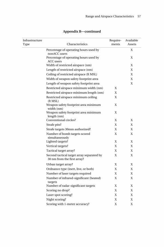
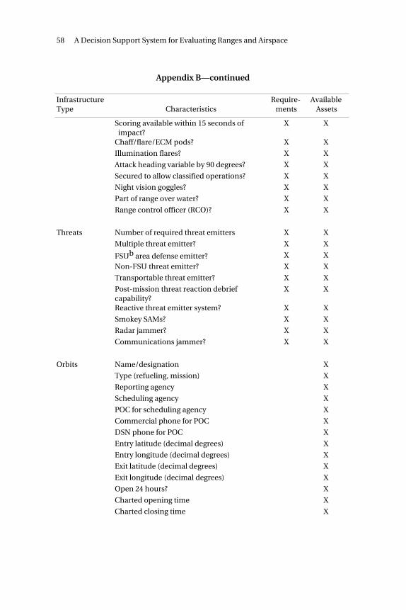
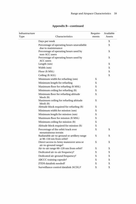
B. RANGE AND AIRSPACE CHARACTERISTICS .......... 53
C. DATA LIMITATIONS ............................ 61
D. HARDWARE AND SOFTWARE REQUIREMENTS ....... 65
ix
FIGURES
2.1 The Analytic Structure........................ 62.2 How Sorties Link Infrastructure to
Operational Tasks ........................... 102.3 Maximum Distance from Base to Range/Airspace ... 122.4 Weapon Safety Footprints, Weapon Safety Footprint
Areas, and Restricted Airspace.................. 152.5 Determining Sortie and Time on
Asset Requirements ......................... 174.1 Sample Table from the Database ................ 285.1 Top-Level Web Page ......................... 365.2 Web Page with Table of Contents................ 375.3 Web Page Comparing Current Assets with
Requirements .............................. 385.4 Web Page to Update Infrastructure Characteristics... 395.5 Web Page to Authenticate a User for
Database Update ........................... 40
xi
TABLES
2.1 RAP Mission Category Sorties for the F-16CG ....... 82.2 Infrastructure Demand: F-16CGs at Hill AFB ....... 204.1 Information Required to Quantify Infrastructure
Demand .................................. 304.2 Selected Standard Queries..................... 32
xiii
SUMMARY
Training aircrews for combat requires access to ranges suitable foractual or simulated weapon delivery and to dedicated airspacesuitable for air-to-air and air-to-ground tactics. However, a numberof commercial, community, and environmental interest groupsincreasingly contest the access of Air Combat Command (ACC) andother military commands to ranges and airspace. To enhance thisaccess, ACC needs a comprehensive, objective statement of its rangeand airspace requirements, linked to national interests, and a meansto compare existing infrastructure with these requirements.
Project AIR FORCE (PAF) and ACC, working in concert, met this needby developing an analytic structure containing the followingelements:
• Operational requirements that aircrews and other combatantsmust be trained to support.
• Training tasks required to prepare aircrews for their assignedoperational tasks.
• Range and airspace characteristics needed for effective supportof each training task.
• Minimum durations of training events on ranges or airspace withspecified characteristics.
• Dimensions, location, equipment, operating hours, and othercharacteristics of current ranges and airspace.
• Relational links among operational requirements, trainingrequirements, infrastructure requirements, and available assets.
xiv A Decision Support System for Evaluating Ranges and Airspace
Elements of the analytic structure are depicted in Figure S.1. Notethat operational missions, objectives, and tasks are referred tocollectively as a joint mission framework. As the figure implies,infrastructure requirements, training requirements, and the jointmission framework must be serially linked. Additionally,infrastructure requirements and current infrastructure must belinked in a way that permits ready comparisons.
This framework called for both a repository of information onvarious elements and a means of representing relationships amongthe elements. A relational database was the tool selected to meetthese needs. The relational database constructed for this purposecontains several embedded models, developed by PAF, that auto-matically complete parts of the assessment process for range and air-space infrastructure. Some models transform user inputs into infra-structure requirements. Another model automatically compares
RAND MR1286AF-S.1
Joint missionsOperational objectives
Operational tasks
Joint mission framework
RangesAirspace
Other
Infrastructure requirements
RangesAirspace
Other
Current infrastructure
Ready aircrew programmissions/sorties
Sortie frequencies
Time in range/airspaceper sortie
Training requirements
Figure S.1—The Analytic Structure
requirements with the existing infrastructure. Additionally, PAFdeveloped several forms of graphical user interface (GUI) to
Summary xv
facilitate user access to the database. The resulting system—arelational database combined with embedded decision models andGUI—can be referred to as a decision support system (DSS). Therange and airspace DSS uses a Microsoft Access database and GUI oftwo types: Access’s native capabilities and a web browser. Similarly,the models are embedded in Access relationships, queries, VisualBasic (VBA) programs, and Web server script programs.
The database contains several types of components, referred to asobjects. These include tables, queries, forms, reports, macros, andmodules. Of these, understanding the functioning of tables andqueries is essential for retrieving information from the database.
Tables contain the stored information in the database. A tablecontains one or more records. Each record contains one or morefields. For example, we have constructed a table that lists each basewith an ACC flying wing, the wing identity, and the latitude andlongitude of the base. In this example, there is a record for eachbase. The fields are name, unit, latitude, and longitude.
Queries are used, as the name implies, to extract information fromthe database. They may be used to view, change, or analyze theextracted data. The most common type is a select query that extractsand displays selected fields from selected records in selected tables.Other types of queries may be used to build or update tables.
To realize the power and potential of the range and airspacedatabase, a continuing investment must be made in developing andemploying the human capital needed to maintain and operate it. Anappropriately trained database administrator must be assigned. Staffand field users must appreciate the system’s capabilities androutinely use them.
The DSS has the potential to serve a much larger staff client basethan originally conceived. ACC/DOR could expand the database toinclude other range and airspace management information that isexchanged routinely between headquarters and field units. Withsome additional investment, it could be expanded to permit efficientcalculations of requirements for other training resources, such asflying hours and munitions. Finally, the DSS can be expanded toinclude requirements and infrastructure from non-ACC range andairspace users. These might include reserve components, Air
xvi A Decision Support System for Evaluating Ranges and Airspace
Education and Training Command, Air Force Materiel Command,and other services.
xvii
ACKNOWLEDGMENTS
The direction and shape of this study were strongly influenced by ColChuck Gagnon, Chief of Range, Airspace, and Airfield Management,Headquarters Air Combat Command, and Maj Michael “Buzz”Russett, our point of contact in that division at the inception of thestudy. Subsequent chiefs—Cols Ron Oholendt and Lynn Wheeless—provided continuing guidance and support, as did Maj Gen DavidMacGhee, who was Air Combat Command’s Deputy Chief of Staff forOperations at a critical point in the study. Colonel Charles Hale, LtCol Art Jean, Lt Col Frank DiGiovanni, Lt Col Dale Garrett, Maj RobBray, Raul Bennett, Kent Apple, and Bob Kelchner, all within theRange, Airspace, and Airfield Management Division, also madesignificant contributions to the project. Kent Bingham, of thePhoto/Graphic Imaging Center at Hill Air Force Base, provided agraphic image of airspace for use in our cover art. During the courseof our research, we visited virtually every ACC operational wing,where local range and airspace managers, operational squadroncommanders, and aircrews arranged for our visits and participated inour interviews.
We are indebted to our Project AIR FORCE program directors,C. Robert Roll and Craig Moore, for their confidence and support.Leslie O’Neill, in RAND’s Langley Air Force Base office, supported usgenerously and capably during our many visits to Headquarters AirCombat Command. Colleagues John Schank and John Stillionprovided insightful reviews, and Jeanne Heller carefully edited themanuscript.
Responsibility for any remaining errors remains, of course, our own.
xix
ACRONYMS
ABCCC Airborne Battlefield Combat and Control Center
xx A Decision Support System for Evaluating Ranges and Airspace
CMR combat mission ready
CSS combat skills sorties
CWDS Combat Weapons Delivery Software
DCA defensive counter air
DOC designed operational capability
DOR Director of Operations, Airspace and Ranges (ACC)
DSN Defense Switched Network
DSS decision support system
ECM electronic countermeasures
FAC-A forward air control aircraft
FSU Former Soviet Union
GUI graphical user interface
JMF Joint Mission Framework
JTIDS Joint Tactical Information Distribution System
INS instrument
LFE large force engagement
MDS mission design series
MFCD maximum free cruising distance
MOA military operations area
MSL mean sea level
MTR military training route
nm nautical mile
OCA offensive counter air
PAF Project AIR FORCE
Acronyms xxi
PAI primary aircraft inventory
PMAI primary mission authorized inventory
RAP Ready Aircrew Program
RPI rated position identifier
SAT surface attack tactics
SMME small multi-MDS engagement
SQL standard query language
SUA special-use airspace
VBA Visual Basic
WSFA weapon safety footprint area
1
Chapter One
INTRODUCTION
BACKGROUND
Training aircrews for combat requires access to ranges suitable foractual or simulated weapons delivery and to dedicated airspace suit-able for air-to-air and air-to-ground tactics. Air Combat Command(ACC) and other military commands responsible for training combataircrews have access to an extensive inventory of ranges andairspace.
Faced with increasing competition for infrastructure usage, ACCrecognized that it needed a requirements-based rather than adeficiency-based approach for determining its range and airspaceinfrastructure needs. In the deficiency-based approach that pre-vailed at the time, range and airspace resourcing alternatives werebased primarily on statements of apparent gaps between require-ments and existing capabilities. Better resourcing decisions could bemade if both the requirements and current asset capabilities werestated more explicitly, with resourcing decisions based on rigorouslyderived assessments of the gaps.
To be defensible, infrastructure requirements must be linked firmlyto training requirements, which in turn must be linked to operationalrequirements that demonstrably serve national interests. Addi-tionally, for a requirements-based approach to succeed, an efficientmeans of comparing existing infrastructure capabilities with thesevetted requirements is needed. RAND’s Project AIR FORCE (PAF)was asked to help in developing these linked sets of requirementsand assets.
2 A Decision Support System for Evaluating Ranges and Airspace
OBJECTIVES AND APPROACH
PAF and ACC, working in concert, determined that ACC’s needscould best be met through the following steps:
• Cataloging aircrew training requirements
• Relating the training requirements to operational requirementsand higher-level national objectives
• Relating the training requirements to supporting range andairspace infrastructure requirements
• Comparing existing range and airspace infrastructure withrequirements.
This framework called for both a repository of information on variouselements and a means of representing relationships among theelements. A relational database was the tool selected to meet theseneeds. In addition to serving the analytic needs of this project, thedatabase could be updated to reflect changes in requirements orexisting assets or expanded as necessary to capture other relatedmanagement information. In the hands of range and airspace man-agers at ACC or elsewhere, it could become a valuable tool forongoing evaluation and management of range and airspace assets.
The relational database constructed to meet these needs containsseveral embedded models, developed by PAF, that automaticallycomplete parts of the range and airspace infrastructure assessmentprocess. Some models transform user inputs into infrastructurerequirements. Another model automatically compares requirementswith existing infrastructure. Additionally, PAF developed severalforms of graphical user interface (GUI) to facilitate user access to thedatabase. The resulting system—a relational database combinedwith embedded decision models and GUI—can be referred to as adecision support system (DSS).
ORGANIZATION OF THE REPORT
Chapter Two describes the elements of the analytic structure weadopted to meet ACC’s needs. In Chapter Three, we provide detailsof the hardware and software implementation of the system. In
Introduction 3
Chapter Four, we provide a tutorial that walks a new user through aWeb-browser-facilitated tour of the database. In Chapter Five, wedescribe the contents of the database. Chapter Six discusses data-base maintenance requirements and opportunities for further devel-opment of the DSS.
5
Chapter Two
ELEMENTS OF THE ANALYTIC STRUCTURE
We required the following elements to fully document range andairspace infrastructure requirements, trace their relevance to train-ing and operational requirements, and assess their adequacy:
• Operational requirements that aircrews and other combatantsmust be trained to support.
• Training tasks required to prepare aircrews for their assignedoperational tasks.
• Range and airspace characteristics needed for effective supportof each training task.
• Minimum durations of training events on ranges or airspace withspecified characteristics.
• Dimensions, location, equipment, operating hours, and othercharacteristics of current ranges and airspace.
• Relational links among operational requirements, trainingrequirements, infrastructure requirements, and available assets.
These elements relate to each other in an analytic structure that isdepicted in Figure 2.1. Operational missions, objectives, and tasksare referred to collectively as a joint mission framework. As the figureimplies, infrastructure requirements, training requirements, and thejoint mission framework must be serially linked. Additionally, infra-structure requirements and current infrastructure must be linked ina way that permits ready comparisons.
6 A Decision Support System for Evaluating Ranges and Airspace
RAND MR1286/1-2.1
Joint Mission Framework
Joint missions
Operational objectives
Operational tasks
Training Requirements
Ready Aircrew Programmissions/sorties
Sortie frequencies
Time in range/airspaceper sortie
Infrastructure Requirements
Ranges
Airspace
Other
Current Infrastructure
Ranges
Airspace
Other
Figure 2.1—The Analytic Structure
We next describe the elements of the range and airspace analyticstructure and document how we developed and populated the vari-ous elements and linkages.
OPERATIONAL REQUIREMENTS: THE JOINT MISSIONFRAMEWORK
In developing this framework, we sought to express commanders-in-chief’s (CINCs’) warfighting needs in terms of desired operationaleffects. Using a strategies-to-tasks concept, we developed a set ofoperational missions, objectives, and tasks to describe how militarypower can be applied jointly. The framework contains 11 jointoperational missions that collectively describe the broad outcomesCINCs seek to achieve in operations ranging from major theater warto smaller-scale peacekeeping and peacemaking contingencies.Within these missions, we identify some 40 operational objectivesand 150 operational tasks.
Elements of the Analytic Structure 7
TRAINING REQUIREMENTS: AN ADAPTATION OF THEREADY AIRCREW PROGRAM
The next element in the analytic structure is a representation oftraining activities needed to prepare aircrews to support operationalrequirements. To complete the linkages envisioned in the analyticstructure, training activities must be related, on one hand, tooperational requirements, and on the other hand, to trainingresource needs, specifically range and airspace infrastructure.1
The DSS focuses primarily on mission qualification and continuationtraining. Undergraduate flying training and initial qualificationtraining are accomplished primarily through formal training coursesand generally do not place demands on ACC range and airspaceinfrastructure.2 Special mission and upgrade training is oftenaccomplished using sorties that are dual-logged as continuationtraining. Thus, demand for ACC ranges and airspace is largely afunction of mission qualification and continuation trainingrequirements.
Mission qualification and continuation training requirements areoutlined in the Air Force’s Ready Aircrew Program. RAP require-ments are contained in mission design series (MDS)-specific, 11-2series Air Force Instructions (AFIs) and in annual tasking messagespublished by ACC. For aircrews in each MDS, RAP specifies a totalnumber of sorties per training cycle, broken down into missiontypes, plus specific weapon qualifications and associated events.The specified number of sorties varies depending on the aircrewmember’s experience and qualification level.3 For example, mission
______________ 1Readers should not infer that training requirements used in our analysis were derivedfrom our joint mission framework. We derived our training requirements from the AirForce’s Ready Aircrew Program (RAP), as described below, which in turn is derivedfrom other representations of operational requirements such as unit designedoperational capability (DOC) statements. We then linked our training requirementsframework to our joint mission framework.2For a few weapon systems, ACC does conduct initial qualification training. Theseprograms usually are co-located with at least one combat squadron and must sharelocal training infrastructure. This study did not include the initial trainingrequirements for these systems; therefore, the total requirement for these bases isunderestimated.3Experienced pilots have accumulated a specified number of flying hours. Forexample, fighter pilots are considered experienced if they have accumulated 500 hours
8 A Decision Support System for Evaluating Ranges and Airspace
category sorties for one type of F-16 for the 1998–1999 RAP cycle areshown in Table 2.1.
Air combat maneuver (ACM) 8 6Basic fighter maneuver (BFM) 3 2 8 6Red air (opposing force for air-opposed training sorties) 8 8Commander option 54 48 18 19
Total 72 60 90 76
_____________________________________________________________ in their primary aircraft, or 1000 total hours of which 300 are in their unit’s primaryaircraft, or 600 fighter hours of which 200 hours are in their unit’s primary aircraft, orwho reached an experienced level in another fighter MDS and have 100 hours in theirunit’s primary aircraft.
Line pilots in operational units generally attain a qualification level designated combatmission ready (CMR). Pilots in staff positions generally attain a lower level ofqualification designated basic mission capable (BMC).
In each training cycle, RAP specifies more sorties for inexperienced aircrew membersthan for experienced aircrew members and more sorties for CMR qualification thanfor BMC qualification. Additionally, RAP may specify more sorties for activecomponent aircrews than for reserve component aircrews.
Elements of the Analytic Structure 9
Sortie Types Used in the Analysis
RAP sorties may be either basic or applied. Basic sorties are building-block exercises, such as air handling characteristics (AHC), basicsurface attack, or basic fighter maneuver, that are used to train fun-damental flying and operational skills. Applied sorties, such as sur-face attack tactics and defensive counter air, are intended to morerealistically simulate combat operations, incorporating intelligencescenarios and threat reaction events.
The examples of sortie types in the preceding paragraph are allfighter-oriented. For nonfighter aircraft, basic sorties are generallyidentified as combat skills sorties (CSS). Applied sorties for non-fighter aircraft are generally identified as SAT sorties (bombers) ormission sorties (for aircraft that do not deliver weapons).
For our analysis, we generally used the RAP sortie structure andannual sortie requirements as a statement of training requirements.However, in some cases, notably SAT, we subdivided RAP sorties intoseveral types (which we refer to as variants) that differ significantlyfrom each other in their infrastructure requirements. For example,fighter SAT missions are divided into air opposed, ground opposed,and live ordnance variants. Similarly, SAT missions for bombers aredivided into inert high/medium level, inert low level, live ordnance,simulated delivery of ordnance, and maritime variants.
We also postulated the need for sorties that combine several MDS,performing different operational roles, in a single training mission.For squadron-size exercises, we used the term large force engagement(LFE) to identify these sorties. For less than squadron-size exercises,we used the term small multi-MDS engagement (SMME). We refer toLFEs and SMMEs collectively as combined sorties. We did not devel-op a comprehensive list of SMMEs. However, we have structuredseveral examples that suggest the possibilities of specifying suchtraining requirements. In general, RAP does not currently specifymulti-MDS sorties except for LFE requirements in some MDS and afew exceptions such as a forward air control aircraft (FAC-A) workingin conjunction with CAS aircraft.
A complete list of the sortie types used in our analysis and their cate-gories and definitions can be found in Appendix A.
10 A Decision Support System for Evaluating Ranges and Airspace
Relating Training Requirements to OperationalRequirements
We determined that applied and combined sorties would be relateddirectly to operational tasks found in our joint mission framework.Basic sorties and variants would be related to various applied sorties,and could then be related indirectly to operational tasks. The rela-tionships are shown in Figure 2.2. Matrices relating variousMDS/sortie combinations to specific operational tasks within thejoint mission framework are too large to be readily included here.However, the linkages are reflected in the range and airspacedatabase we constructed and can be extracted for any MDS, sortietype, or joint mission. As an example, the joint mission “Deny theenemy the ability to operate ground forces” contains an operationalobjective “Halt invading armies,” within which one of the opera-tional tasks is “Delay/destroy/disrupt lead units of invading armies.”For the F-16CG, the database associates this operational task withthree types of applied sorties (CAS, DCA, and LFE) and five types ofbasic sorties (instrument [INS], AHC, ACM, BFM, and BSA). Rangeand airspace infrastructure required for the F-16CG for each of thesesortie types can also be extracted from the database and linked tothis operational task.
RAND MR1286/1-2.2
Joint Mission Framework
Operational missionsOperational objectives
Operational tasks
Applied sorties(Single MDS)
Basic sorties
Applied sorties(Combined)
Variants
Infrastructure
Figure 2.2—How Sorties Link Infrastructure to Operational Tasks
Elements of the Analytic Structure 11
REQUIRED INFRASTRUCTURE CHARACTERISTICS
The next element in our analytic system is a statement of the rangeand airspace infrastructure needed to support training requirements.To be useful for training, the range and airspace infrastructure musthave certain geographical, qualitative, and quantitative characteris-tics. Geographically, it must be reasonably proximate to base operat-ing locations. For many MDS, especially fighters, extending aircraftrange through air refueling is not a viable option for training sorties.Even for longer-legged bomber and command, control, intelligence,surveillance, and reconnaissance (C2ISR) aircraft, other constraintssuch as crew duty-day length and flight time engaged in useful train-ing versus time spent cruising to and between training areas need tobe considered. Qualitatively, the infrastructure must have minimumdimensions, equipment, authorization for operating aircraft andsystems in specified ways, and other characteristics. Quantitatively,the time available on proximate ranges and airspace must be suffi-cient to support the training requirements at an operating base. Inthis and the following sections, we discuss how these infrastructurerequirements were developed and are represented in the range andairspace information system.
Distance from Base to Range/Airspace
Ranges and airspace must be reachable with the maximum fuel loadconsistent with the sortie type. Further, fuel available for cruising to,from, and between ranges and airspace must take into account theamount of fuel consumed during training events.4 Because manysortie types require access to more than one asset (e.g., a low-levelroute, a maneuver area, and a range) during a given sortie, therequired geographical proximity of the assets cannot be adequatelyexpressed in terms of a radius from the base. It is better expressed interms of a maximum for the sum of the free cruising legs between
______________ 4We use the term training event to indicate a part of a sortie with a specific trainingfocus. For example, an air-to-ground sortie may include a low-level navigation leg, athreat evasion exercise, and a series of weapon deliveries. In our usage, these training-related components of the sortie are referred to as a training event.
12 A Decision Support System for Evaluating Ranges and Airspace
RAND MR1286.1-2.3
Maneuverarea
Maneuverarea
Range
Base
Low-levelroute
Air-to-air sortie:
• No low-level route required• Base-to-area < 1/2 max.
Figure 2.3—Maximum Distance from Base to Range/Airspace
assets (see Figure 2.3). We calculated this maximum for eachMDS/sortie-type combination and used it to analyze the geographi-cal relationships of bases, ranges, and airspace.
To calculate the maximum free cruising distance for eachMDS/sortie-type combination, we interviewed aircrew members todetermine the normal external fuel-tank configuration and fuelcapacity for the sortie; fuel consumption for taxi, takeoff, and climb;fuel consumption during training events en route, in the area and/oron the range; and reserve fuel requirements. To determine fuel con-sumption, we first determined standard minimum durations for eachtraining event. We determined reasonable values for these mini-mums through consultation with experienced aircrew members.
Subtracting required consumptions and reserve from fuel capacityyields the amount of fuel that can be used for free cruising legs.Dividing this amount by an average fuel consumption rate at a typi-cal cruising speed and altitude yields the maximum free cruisingtime. Multiplying this time by the typical cruising speed gives the
Elements of the Analytic Structure 13
maximum free cruising distance. Maximum free cruising distancesranged from 79 miles for F-15C BFM sorties to 1757 miles for B-52SAT sorties. In general, fighters and helicopters are far more limitedin their free cruising distances than are bombers and C2ISRplatforms.
Qualitative Requirements
Qualitative infrastructure requirements (e.g., range dimensions,equipment, operating authorizations) were developed primarilythrough capturing the judgment of experienced aircrew members.In general, we used the MDS/sortie-type combination as the unit ofanalysis (i.e., each MDS/sortie-type combination would have its ownunique set of infrastructure requirements represented in the data-base). However, where choice of events would significantly alter theinfrastructure requirement, we divided the RAP sortie into two ormore variants, as discussed in the previous section of this chapter.This enabled us to better reflect specific infrastructure standards forthe wide variety of crew activity being logged under any one sortietype.
As an exception to the general rule of using the MDS/sortie-typecombination as the unit of analysis, we found that for range charac-teristics related to weapon deliveries, it was necessary to use thetraining event (i.e., the weapon delivery type) as the unit of analysis.Weapon deliveries can vary by release altitude, release type (level,loft, dive, etc.), weapon type (rocket, gravity bomb, guided munition,etc.), level of threat (which affects assumed accuracy of the delivery),and MDS.5 Weapon delivery type affects two categories of rangecharacteristic requirements—restricted airspace dimensions andweapon safety footprint area (WSFA) dimensions. To specifystandard range requirements for weapon deliveries at an MDS/sortie-type level of analysis, we would have to identify the mostdemanding (in terms of these range characteristics) weapondeliveries that aircrews should routinely employ in each MDS/sortiecombination. However, we found no basis for selecting whichweapon delivery types should be used to set these requirements.
______________ 5ACC currently identifies 210 distinct weapon delivery types.
14 A Decision Support System for Evaluating Ranges and Airspace
Thus, restricted airspace and WSFA requirements are expressed atthe event rather than the MDS/sortie-type level in our analysis.
Organizing the Qualitative Requirements
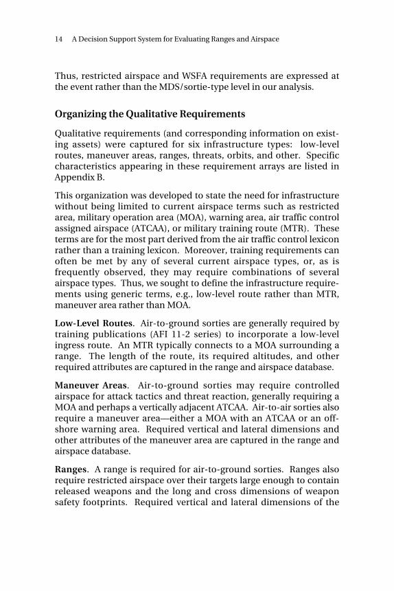
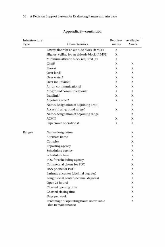
Qualitative requirements (and corresponding information on exist-ing assets) were captured for six infrastructure types: low-levelroutes, maneuver areas, ranges, threats, orbits, and other. Specificcharacteristics appearing in these requirement arrays are listed inAppendix B.
This organization was developed to state the need for infrastructurewithout being limited to current airspace terms such as restrictedarea, military operation area (MOA), warning area, air traffic controlassigned airspace (ATCAA), or military training route (MTR). Theseterms are for the most part derived from the air traffic control lexiconrather than a training lexicon. Moreover, training requirements canoften be met by any of several current airspace types, or, as isfrequently observed, they may require combinations of severalairspace types. Thus, we sought to define the infrastructure require-ments using generic terms, e.g., low-level route rather than MTR,maneuver area rather than MOA.
Low-Level Routes. Air-to-ground sorties are generally required bytraining publications (AFI 11-2 series) to incorporate a low-levelingress route. An MTR typically connects to a MOA surrounding arange. The length of the route, its required altitudes, and otherrequired attributes are captured in the range and airspace database.
Maneuver Areas. Air-to-ground sorties may require controlledairspace for attack tactics and threat reaction, generally requiring aMOA and perhaps a vertically adjacent ATCAA. Air-to-air sorties alsorequire a maneuver area—either a MOA with an ATCAA or an off-shore warning area. Required vertical and lateral dimensions andother attributes of the maneuver area are captured in the range andairspace database.
Ranges. A range is required for air-to-ground sorties. Ranges alsorequire restricted airspace over their targets large enough to containreleased weapons and the long and cross dimensions of weaponsafety footprints. Required vertical and lateral dimensions of the
Elements of the Analytic Structure 15
restricted area, types of targets, scoring systems, and other relatedrange attributes are specified in the range and airspace database.The relationship of weapon safety footprints, WSFAs, and restrictedairspace is illustrated in Figure 2.4.6
f f
RAND MR1286AF-2.4
Footprintlong
Footprintcross
Targetarray
Footprintcross
Weapon safetyfootprint area
Footprintshort
Restrictedairspace
Weapon release
Figure 2.4—Weapon Safety Footprints, WeaponSafety Footprint Areas, and Restricted Airspace
______________ 6To calculate WSFA and restricted airspace requirements, RAND used (1) weaponsafety footprint data for 210 distinct delivery types, obtained from ACC/DOR in August1999, (2) an assumed target array size of 2 nm × 2 nm, and (3) weapon release pointscalculated using Combat Weapons Delivery Software (CWDS) provided by the MissionPlanning Support Facility, OO-ALC/LIRM, Hill Air Force Base, UT.
Note that Figure 2.4 provides the WSFA and restricted airspace requirements for only asingle axis of attack. For multiple axes of attack, the dimensions shown in Figure 2.4must be rotated around the target.
16 A Decision Support System for Evaluating Ranges and Airspace
Threats. Many air-to-ground sorties require ground-based radarthreat emitters or communications jammers, which may be installedon a range, beneath a MOA, or conceivably at points along an MTR.We determined that the training requirement would be met if thethreat emitters were installed in any of these locations. Thus, ratherthan include threat requirements within range, area, and routerequirements arrays, we established a separate threat requirementsarray in the range and airspace database.
Orbits. Orbits may be required for air refueling or certain commandand control missions. The requirement is captured in the range andairspace database. Orbits can be flown in a MOA or ATCAA, but areusually specified only in a letter of agreement with the affected airroute traffic control center (ARTCC).
Other. Some sorties require a specific other aircraft for effectivetraining. For example, DCA and offensive counter-air (OCA) sortiesrequire Red air opponents. Others require an air or ground weaponsdirector. Requirements such as these are not, strictly speaking, partof the range or airspace infrastructure. However, in the interest ofmore completely documenting training requirements, we collectedsuch noninfrastructure requirements that came to our attention.7
Capacity
The amount of operating time required on ranges and in airspacecan be calculated, for a given MDS/sortie-type combination, bymultiplying the required number of sorties by the time required foran individual sortie on a range and/or in an airspace. After certainadjustments (discussed below), the results can be summed across allMDS/sortie-type combinations to determine a base’s total localdemand for ranges and airspace (referred to as assets in Figure 2.5and Chapter Six). This demand is computed and recorded in therange and airspace database for each base/MDS/sortie-type
______________ 7Pilots we interviewed said that training with other MDS is very important, but thelack of a requirement for such training often discouraged an already-busy potential“partner MDS” from participating.
Elements of the Analytic Structure 17
RAND MR1286-2.5
RPI 1 pilots
Total pilots
Sorties per periodby crew type (inexperienced/CMR,experienced/CMR,experienced/BMC)
Adjusted sortiesper period
Required time onasset per period
PAI × crew ratio
RPI 1 pilots + RPI 6 pilots
total pilots × ×
=
=
=
=
where
=
modified RAP sortierequirements by
crew type
sum of sorties per period across all crew types
crew typeproportion
efficiencyfactor×
×
×
flight size
1 – sortie attrition rate
efficiencyfactor
1 + schedulinginefficiency rate
1 + noncontinuationsortie rate
=
adjusted sortiesper period
time on assetper sortie
Figure 2.5—Determining Sortie and Time on Asset Requirements
combination. In the following paragraphs, we discuss, first, how therequired number of sorties is calculated and, second, how the timerequired for each sortie is determined.
Required Number of Sorties. The database contains a table that liststhe total number of annual sortie requirements by base, MDS, andsortie type. To populate this table, we determine the number ofpilots in each MDS at each base and multiply that number by theannual requirement for each sortie type.8 The required calculationsare shown in Figure 2.5 and described below.
To determine the number of pilots, we first obtain the primarymission authorized inventory (PMAI) by MDS and base. Thesecounts are multiplied by the crew ratio for the MDS, yielding the
______________ 8In some MDS, crew positions other than pilot also require training. However, wefound no MDS with a crew position that required more sorties than did the pilot.Thus, using pilot counts alone (excluding co-pilots) as the basis for annual sortierequirements is sufficient to establish an upper bound on sortie demand.
18 A Decision Support System for Evaluating Ranges and Airspace
expected number of RPI 1 (RPI = rated position identifier) pilots onthe base.9 To this number, we add the number of RPI 6 pilots by baseand MDS.10 The total number of pilots is then distributed toexperienced/inexperienced and BMC/CMR categories.11
The next step in determining the total sortie requirement is to mul-tiply the number of pilots by the number of annual sorties requiredin each MDS/sortie-type combination. The number of sorties ineach training cycle (generally one year) for experienced/inexperienced and BMC/CMR categories is specified by sortie typeand MDS in annual RAP tasking messages.
For our analysis, we modify the raw RAP counts in several ways. Weuse assumed rates to redistribute RAP sortie counts to our modified-RAP variants. Additionally, we distribute the the commander’soption sorties to specific sortie types in the same proportions thatthe specific sorties had relative to each other, i.e., if SAT sorties are40 percent of the noncommander’s option sorties, we distribute40 percent of the commander’s option sorties to SAT.12
The next step in computing the sortie requirement is to adjust forflight size. When two-ship or four-ship flights use a range or air-space, multiple aircrews obtain training in the same time period.Thus, the critical factor in quantifying range and airspace demand isnot the annual number of sorties but rather the annual number offlights. To convert sortie counts to flight counts, we divide sortiecounts by an assumed average flight size for each MDS/sortie-typecombination.
______________ 9RPI 1 identifies line pilots (excluding commander and operations officer) occupyingcockpits in operational squadrons.10RPI 6 identifies commanders, operations (ops) officers, and pilots in staff positions.11For these calculations, we consider RPI 6 positions, except commander and opsofficer, to be experienced and BMC. Commander and ops officer are consideredexperienced and CMR. RPI 1 pilots are considered CMR and are distributed usingassumed rates between experienced and inexperienced categories.12RAP specifies the number of sorties by type that each aircrew member must fly in atraining cycle. Additionally, it specifies a number of sorties that can be of any type,depending on the commander’s judgment of where the individual or unit needstraining emphasis.
Elements of the Analytic Structure 19
The final step in developing and adjusting the sortie requirement isto inflate the count to account for attrition (maintenance andweather cancellations), scheduling inefficiency, and noncontinua-tion training sorties. Some scheduled sorties cannot be completedbecause of either maintenance or weather aborts. Although theseaborted sorties do not satisfy training requirements, they nonethelessconsume available time on ranges and airspace because thescheduled time generally cannot be reallocated on short notice (inthe case of maintenance aborts) or used by other aircrews (in thecase of weather or mission conflict aborts).13 A scheduling ineffi-ciency factor accounts for the fact that perfectly efficient scheduling,using 100 percent of available range or airspace time, would tend tosuboptimize overall aircrew time management because it wouldadversely affect aircrew workday and work/life balance considera-tions. Finally, some but not all upgrade and special qualification sor-ties are dual-logged as RAP sorties. The noncontinuation traininginflation factor builds a range/airspace infrastructure requirementfor upgrade and special qualification sorties that are not dual-logged.The range and airspace database uses assumed values for these threefactors (10 percent for each factor).
Time Required per Sortie on Range and/or in Airspace. A table indi-cating time required per sortie on a range or in an airspace, by MDSand sortie type, is found in the database. See, for example, times inTable 2.2. The times shown in this table (minimum training eventdurations) are assumed values based on interviews with WeaponsSchool and operational unit aircrews. They represent minimumsconsidered necessary for the sortie to produce some standardizedtraining value.
Total Demand. Total range and airspace time requirements by base,MDS, and sortie type are calculated and reflected in a table in thedatabase. Table 2.2 reflects, for example, an extract of this part of the
______________ 13A few units fly a large number of sorties on ranges that they do not control, whichcan result in a mission conflict. Usually, once a unit contracts for time on a range,there is little chance of mission conflicts with the owning unit. However, we found atleast one range (White Sands Missile Range Complex) where the range time could becanceled by range controllers within 15 minutes before entry time. In this case, fighteraircraft are already airborne when they are canceled.
20 A Decision Support System for Evaluating Ranges and Airspace
database for F-16CGs at Hill AFB. This requirement can be inter-preted as a demand for maneuver airspace time for air-to-air sortietypes and as a demand for both maneuver airspace and range timefor air-to-ground sortie types. It is determined, as shown in Fig-ure 2.5, as the product of total requirements for a given base/MDS/sortie-type combination multiplied by the time required onasset for that MDS/sortie-type combination.
Data Limitations. Lack of available empirical data and other relatedproblems required us to estimate many of the factors used to com-pute capacity requirements. A discussion of these limitations is pro-vided in Appendix C.
CURRENT INFRASTRUCTURE
Information regarding the characteristics of ranges and airspacecommonly used by ACC aircrews was collected (by e-mail) byACC/DOR during late 1998 and early 1999. Preformatted Excelspreadsheets were sent as attached documents to local rangemanagers and airspace schedulers, who entered the required infor-mation in the spreadsheets and returned them to ACC/DOR. Thespreadsheets were subsequently forwarded to PAF to be incorporatedin the database. Subsequently, a capability was provided to permitlocal range managers and airspace schedulers to update thesecharacteristics via a Web interface. Specific characteristics tracked inthe range and airspace database are listed in Appendix B. They canbe found in various tables in the database and in selected displays
Elements of the Analytic Structure 21
available via a Web browser. Limitations on the available data arediscussed in Appendix C.
COMPARISON OF CURRENT INFRASTRUCTURE WITHREQUIREMENTS
An important element of our analytic structure is a capability tocompare requirements and resources. Linkages and models embed-ded in the range and airspace database permit current infrastructureand requirements to be compared for each MDS/sortie-type combi-nation. These comparisons are reflected in a series of tables in thedatabase and in a display accessible via a web browser. The examplefrom the web browser shown in Chapter Five, Figure 5.3, depicts anassessment of maneuver areas for F-15C DCA sorties. Each rowrepresents a different maneuver area (identified in the “name”column). Characteristics of the various areas are shown under“width,” “length,” etc. Characteristics that meet requirements areshaded light gray (green on the web) while those that do not meetrequirements are shaded dark gray (red on the web). This screendepicts only part of a much larger matrix containing all areas and allcharacteristics of areas.
23
Chapter Three
ELEMENTS OF THE DECISION SUPPORT SYSTEM
A CONCEPTUAL DESCRIPTION OF THE DSS
A DSS provides measures of performance that a decisionmaker canuse with his own expertise in making a decision. The measures ofperformance require one or more models that capture intrinsicrelationships. In the present case, the models capture therelationships among operational requirements (a joint missionframework), aircrew training requirements, range and airspaceinfrastructure requirements, and available infrastructure.
To do their job, the models must include data on the joint missionframework (JMF), on which training sorties contribute to the JMFobjectives and tasks, and infrastructure requirements and assets.These data are captured in formal databases. On the other hand, theinteractions between the DSS and the user need to be facilitated by auser-friendly interface: a graphical user interface (GUI) similar tothat used in Macintosh and Windows software. Overall, a DSSrequires databases, models, and GUI.
The database for the range and airspace DSS is implemented inMicrosoft Access. The models included in the DSS are embedded inAccess relationships, queries, Visual Basic (VBA) programs, and webserver script programs. The DSS uses GUI of two types: Access’snative capabilities and a web browser. These elements of the DSS arediscussed in more detail below.
24 A Decision Support System for Evaluating Ranges and Airspace
DATABASE AND MODELS EMBEDDED IN MICROSOFTACCESS
Data tables and relationships among the tables are the mostprominent features of Access, but Access also incorporates featuressuch as queries, semantic information (e.g., description fields), anduser-defined functions and subroutines (in VBA modules). In therange and airspace DSS, these relationships, queries, functions, andsubroutines are used to create models that help estimateinfrastructure requirements and then help compare the requiredwith the actual infrastructure by creating a color-coded chart thathighlights which available infrastructure can or cannot meet specificrequirements. The web interface to the DSS also obtains its datafrom the Access database, as noted in the web section below.
USER INTERFACE VIA ACCESS
Access’s GUI facilitates updating the various tables in the databasethrough views similar to grids or spreadsheets. This GUI also candisplay a diagram of table relationships (via its Tools -> Relationshipsmenu).
Furthermore, Access provides a diagrammatic display of rela-tionships embedded within each query, complementing the rela-tionships diagram noted above. For the analyst with a good under-standing of Access and the range and airspace DSS, Access simplifiesthe creation of ad hoc queries that may provide new measures ofperformance useful in assessing the current infrastructure.
Finally, Access’s GUI simplifies the documentation of database,tables, and models by making available its various description fields.
USER INTERFACE VIA A WEB BROWSER
Access is sufficient to share data among a few users at one location,but it becomes more cumbersome when retrieval and update of datafrom multiple locations are required. Local base range and airspacemanagers are integral parts of the infrastructure system beingmodeled. To facilitate their use of the DSS, tools such as webbrowsers and a server are required.
Elements of the Decision Support System 25
A web server is a program that runs at a central location and allowsthe viewing of data and graphics by a large number of users indifferent locations. The web server is the program that responds torequests from each user’s web browser to display or update specifieddata. In the range and airspace DSS, the web server pulls datadirectly from the Access database.
The query capabilities provided by the web browser/server interfaceare quite limited relative to the full ad hoc query capabilities ofAccess. Thus, some users will want to obtain the full database forquery purposes rather than relying on web-based queries.
HARDWARE AND SOFTWARE REQUIREMENTS
The system was designed to operate with hardware and softwaregenerally available in Air Force desktop systems and serverenvironments. Detailed specifications are provided in Appendix D.
27
Chapter Four
WHAT IS IN THE DATABASE
A database may contain several types of components, referred to asobjects. The types of objects found within Access are tables, queries,forms, reports, macros, and modules. Of these, an understanding oftables and queries is essential for retrieving information from thedatabase.
In this chapter, we provide an orientation to the major tables andqueries and a brief discussion of the use of forms, reports, macros,and modules in the database. Our purpose here is to assist a userwho is familiar with Access to rapidly gain an ability to extract infor-mation from the database. This orientation is not designed to pre-pare a user to maintain the database. Additional training may beneeded to prepare a user for maintenance responsibilities.
TABLES
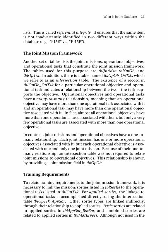
Tables contain the stored information in the database. A table con-tains one or more records. Each record contains one or more fields.For example, we have constructed a table that lists each base with anACC flying wing, the wing identity, and the latitude and longitude ofthe base. See Figure 4.1. In this example, there is a record for eachbase. The fields are name, unit, latitude, and longitude.
28 A Decision Support System for Evaluating Ranges and Airspace
Figure 4.1—Sample Table from the Database
Master Lists
One group of tables provides master lists of key variables in thedatabase. One such table, labeled tblMDS, lists all mission designseries (MDS) for which training and infrastructure requirementshave been identified and provides a description and other infor-mation regarding the MDS. Another such table, labeled tblSortie,lists all mission/sortie types and defines each. In addition to pro-viding a repository for definitions and other basic informationrelated to the key variables, these tables also ensure consistentterminology throughout the database. In other tables, whenever anMDS or sortie field is used, the database ensures that each entry inthe MDS or sortie field matches an entry in the MDS or sortie master
What Is in the Database 29
lists. This is called referential integrity. It ensures that the same itemis not inadvertently identified in two different ways within thedatabase (e.g., “F15E” vs. “F-15E”).
The Joint Mission Framework
Another set of tables lists the joint missions, operational objectives,and operational tasks that constitute the joint mission framework.The tables used for this purpose are tblJntMsn, tblOpOb, andtblOpTsk. In addition, there is a table named tblOpOb_OpTsk, whichwe refer to as an intersection table. The existence of a record intblOpOb_OpTsk for a particular operational objective and opera-tional task indicates a relationship between the two: the task sup-ports the objective. Operational objectives and operational taskshave a many-to-many relationship, meaning that an operationalobjective may have more than one operational task associated with itand an operational task may have more than one operational objec-tive associated with it. In fact, almost all operational objectives havemore than one operational task associated with them, but only a veryfew operational tasks are associated with more than one operationalobjective.
In contrast, joint missions and operational objectives have a one-to-many relationship. Each joint mission has one or more operationalobjectives associated with it, but each operational objective is asso-ciated with one and only one joint mission. Because of their one-to-many relationship, an intersection table was not required to relatejoint missions to operational objectives. This relationship is shownby providing a joint mission field in tblOpOb.
Training Requirements
To relate training requirements to the joint mission framework, it isnecessary to link the mission/sorties listed in tblSortie to the opera-tional tasks listed in tblOpTsk. For applied sorties, the linkage tooperational tasks is accomplished directly, using the intersectiontable tblOpTsk_AppSor. Other sortie types are linked indirectly,through their relationship to applied sorties. Basic sorties are relatedto applied sorties in tblAppSor_BasSor, and combined sorties arerelated to applied sorties in tblMMEspecs. Although not used in the
30 A Decision Support System for Evaluating Ranges and Airspace
current analysis, a framework for analyzing a training sortie in termsof its included events can be found in tblTrnEvt.
Quantifying Demand
Data used to quantify the demand for infrastructure are spreadamong a number of tables, as indicated in Table 4.1.
Infrastructure RequirementsTo determine the infrastructure requirements for a given MDS/sortiecombination, one refers to the appropriate record in tblMDS_Sortie_Infra. This record refers, in turn, to a record in tblInfraStruct that
Table 4.1
Information Required to Quantify Infrastructure Demand
Information TableNumber of PMAI aircraft by MDS and base tblPMAIRAP sortie requirements by pilot class tblRapSortieReqmts
a
Weights used to distribute RAP sorties to the modi fied-RAP sortie definitions used in the database
tblRapSortieDistribution
Modified-RAP sortie requirements by pilot classb tblRaSortieReqmts
Crew ratios tblCrewRatioRPI 6 inventories tblRpi6InventoryTotal modified-RAP sortie requirements by base and MDS
tblMdsBaseRaSortie
Duration of training time on range or in airspace, average flight size, sortie attrition rate, scheduling inefficiency rate, and noncontinuation training sortie rate, by MDS and modified-RAP sortie
tblSor_Mds_Infra
aThis table was developed with infrastructure resource demand in mind, and assuch should be used with caution for other purposes. For example, for F-15C, thereis a significant Red Air sortie allocation in the RAP tasking message that is notreflected in tblRapSortieReqmts. If this were included there would be a double-counting of infrastructure demand—once for the F-15Cs and once for the aircraftthey oppose as Red Air.bSee discussion of modified-RAP sortie types under the heading “Sortie Types Usedin the Analysis” in Chapter Two. Note that we use the segment “Rap” in the labelsof tables and queries that contain original RAP sortie information and the segment“Ra” in labels of tables and queries that contain modified-RAP sortie information.
What Is in the Database 31
acts as a directory record to tables containing requirements forvarious kinds of infrastructure.1 These templates appear as recordsin the series of tables labeled tblTpRoute, tblTpArea, tblTpRange, tblTpOrbit, tblTpThrtEC, and tblTpOther (“Tp” indicates “template”).2
Additionally, tblFootprints provides dimensional requirements foreach type of weapon delivery event.
Current Infrastructure
Information on current infrastructure is contained in a series oftables labeled tblInfraItemRoute, tblInfraItemArea, tblInfraItemRange, and tblInfraItemOrbit.
Infrastructure Evaluations
A series of tables contains the results of comparing each currentinfrastructure item with the requirements for each MDS/sortiecombination. Entries in these tables indicate whether or not theinfrastructure meets the requirement. These tables are labeled tblMatchingRoute, tblMatchingArea, tblMatchingRange, and tblMatchingOrbit. Additionally, tblMatchingRangeDelivery providescomparisons of each weapon delivery event’s requirements witheach range’s characteristics.
QUERIES
Queries are used, as the name implies, to extract information fromthe database. They may be used to view, change, or analyze theextracted data. The most common type is a select query that extractsand displays selected fields from selected records in selected tables.Other types of queries may be used to build or update tables.
______________ 1tblMDS_Sortie_Infra does not serve this directory role because a number ofMDS/sortie combinations could have a common infrastructure requirement. Whenthis is the case, they all refer to the same infrastructure record in tblInfraStruct.2For similar multiple-use reasons, the individual infrastructure templates do notappear directly within the rows of tblInfraStruct. Perhaps more important, thehierarchical layering serves to organize the infrastructure requirements and facilitatescomparison with actual training infrastructure resources.
32 A Decision Support System for Evaluating Ranges and Airspace
Several standard queries have been constructed for recurringdatabase maintenance tasks or for anticipated recurring analysisneeds. Some of these are listed in Table 4.2.
Table 4.2
Selected Standard Queries
Query Name Information or Processtbl MDS_Infra List of all infrastructure requirements, by MDS
and modified-RAP sortietbl OpObj_MDS List of operational objectives and tasks associ-
ated with a selected MDS or sortie typetbl Op Tsk_Basic Sortie A complex inquiry that relates basic sorties and
variants indirectly, through applied sorties, tooperational tasks
qselComputeInfraTimeReqmt Computation of time required on range or assetfor each base/MDS/sortie combination
quniMdsBase Gives pilot experience/qualification breakout foreach MDS/base combination. A complex querythat pulls information from multiple sources.Experienced BMC pilots come from the RPI 6data in tblRpi6Inventory. CMR pilots are com-puted from the crew ratio and experience levelsin tblMds, and the PMAI values in tblPMAI. Thisquery result has the logical status of a table.
qmakMdsBaseRaSortie Combines the pilot class and pilot count infor-mation in quniMdsBase with the sortie require-ments by pilot class in tblRaSortieReqmts to con-struct the sortie requirement for the base.Broken out by MDS and sortie type for each base.
qselRaSortieReqmts Distributes the RAP sortie requirements fromtblRapSortieReqmts onto the modified-RAP sor-ties using the weights in tblRapSortieDistribution. Grouped by MDS, sortie, and pilotclass.
qmakBaseRange This combines tblBase with tblInfraItemRange tocreate tblBaseRange, which includes the distancebetween the base and range. It uses the macroSeparationLatLong.
qselRaSortieReqmts Builds the sortie requirements by MDS/sortie/pilot class from tblRapSortieReqmts andtblRapSortieDistribution.
What Is in the Database 33
FORMS
Forms are used to provide an improved graphic interface on thecomputer screen, facilitating the display or entry of data. Since datacan be entered directly into a table or displayed in the form of a tableor query result, forms are not essential to use of the database.However, they can be very useful in making the database accessibleto nonexpert users or to control input of data from outside sources.
REPORTS
Reports are similar to forms but are designed to produce a user-friendly display of data on the printed page rather than the computerscreen. No standard reports have been developed for the range andairspace database.
MACROS AND MODULES
Macros are routines saved by users to facilitate the execution ofrecurring tasks. Modules are collections of Visual Basic code savedby users for execution of recurring tasks. This project has usedmodules for various functions involved in the construction of thedatabase. The module file sptQryAssessRanges, for instance, containsfunctions that are directly evaluated in the process of comparinginfrastructure with requirements.
NAMING CONVENTIONS
Although Access has liberal rules for naming tables, queries, forms,and fields within it, we adopted somewhat more stringent conven-tions for naming the essential components of the range and airspacedatabase. We anticipated that development of some database fea-tures might require Visual Basic programming or manually authoredSQL statements. To facilitate such programming, we adopted aconvention of avoiding blank characters within names of thestandard objects. Likewise, for field labels, we decided to avoid blankcharacters.
34 A Decision Support System for Evaluating Ranges and Airspace
To have the name indicate the object type, we attach a prefix indi-cating the object type: tbl for tables and frm for forms. For queries,we use one of several prefixes to denote the query type. These are:
qapp for an append query
qdel for a delete query
qmak for a make-table query
qsel for a select query
quni for a union query
qupd for an update query.
If a table, query, or form does not have one of these prefixes in itsname, it is generally an ad hoc retrieval or display of information.Several of these are provided as examples of how the database can beused.
Our discipline in adhering to these conventions was not perfect.Occasional violations of our naming conventions do not impair thefunctionality of the database or prevent use of the affected names inprogramming; they simply make their use less convenient.
35
Chapter Five
A WEB “TOUR” OF THE SYSTEM
The database and its web interface were designed to be installed on aserver at Hq ACC with a hyperlink from the ACC/DOR home page.This chapter, designed to be used by a reader with access to thedatabase via a web browser, takes the reader through a brief tour ofthe system.
BASIC INQUIRIES
Figure 5.1 displays the top page which, in turn, leads to the rest of theweb DSS.
Clicking on the hyperlink at the bottom of the top page leads to thesystem’s table of contents, as shown in Figure 5.2.
The table of contents page shows the user some of the logic of theembedded models:
• Starts with the joint mission framework
• Presents a definition of sortie types and infrastructure resourcecategories (e.g., ranges, routes, etc.)
• Links the JMF to sortie requirements, then shows, for eachinfrastructure resource category, the supporting infrastructurecharacteristics required for each type of sortie
• Presents the characteristics of existing infrastructure
36 A Decision Support System for Evaluating Ranges and Airspace
Figure 5.1—Top-Level Web Page
• Compares the requirements and availabilities for user-specifiedsorties and infrastructure resources (a color-coded display sum-marizes the results).
In addition to generating lists of useful information (e.g., MDS char-acteristics or range location displayed in a map of the United States),the DSS can identify infrastructure resources within a user-specifieddistance from a particular base. More important, it can showwhether a certain infrastructure resource—say, a particular range—has the needed characteristics for specified sortie types and relatedtraining needs (e.g., whether a specified range has laser scoringcapability).
A Web “Tour” of the System 37
Figure 5.2—Web Page with Table of Contents
ADVANCED USE OF THE DSS
At a more advanced level, color-coded displays generated by the DSScan be used to compare the actual characteristics of an infrastructureresource, say, a range, with the requirements of a particular MDS/sortie-type combination (see Figure 5.3).
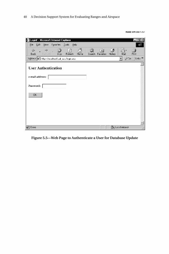
Providing local range and airspace managers a convenient process toupdate the characteristics of existing infrastructure resources is keyto maintaining current information on existing assets. The rangeand airspace DSS provides this capability. The page used to invokethe update process is shown as Figure 5.4. Software in the DSSchecks to ensure that updates to the database are accepted only from
38 A Decision Support System for Evaluating Ranges and Airspace
Figure 5.3—Web Page Comparing Current Assets with Requirements
specified sources. The page used for this verification is shown asFigure 5.5. As a further protection against erroneous updates, asystem administrator must validate the new data entries beforemaster copies of database tables are updated. Additionally, thesystem administrator must run models offline to update the resultsprovided in color-coded displays.
A Web “Tour” of the System 39
Figure 5.4—Web Page to Update Infrastructure Characteristics
40 A Decision Support System for Evaluating Ranges and Airspace
Figure 5.5—Web Page to Authenticate a User for Database Update
41
Chapter Six
SYSTEM MAINTENANCE AND DEVELOPMENT
This chapter discusses both ongoing requirements for maintenanceof the range and airspace DSS and the need for additional develop-ment. Additional development is required both to eliminate cur-rently identified system shortcomings and to add usefulfunctionality.
KEEPING THE SYSTEM VIABLE
The range and airspace DSS provides a powerful tool for range andairspace managers and a potential tool for other aircrew trainingresource managers. The system requires an administrator with thefollowing competencies:
• Database update, retrieval, and development
• Visual Basic programming
• Interfaces among databases, web servers, and web browsers
• Familiarity with aircrew continuation training requirements
• Familiarity with range and airspace infrastructurecharacteristics.
Additionally, other range and airspace managers must become famil-iar with the DSS’s contents and capabilities so that they can placeappropriate demands upon it. Also, as motivation to keep the systemupdated, data sources must perceive that the DSS is used advanta-geously in addressing critical issues. It is axiomatic that a system per-ceived to be unused will also be poorly maintained.
42 A Decision Support System for Evaluating Ranges and Airspace
DATA MAINTENANCE ISSUES
Almost all the data in the DSS are subject to change and thereforeneed to be maintained.
Joint Mission Framework
The JMF does not change rapidly at the strategic level, but one canexpect that as weapon systems evolve and as experience is gained intheaters such as Kosovo, the match of operational tasks to objectiveswill evolve.1 Several changes per year at this level of the JMF can beexpected. Additionally, the database will have to be changed toreflect modifications to the linkages between operational tasks andtraining sorties. This is probably best done centrally and at leastannually.
Training Requirements
Training requirements will change, as indicated above, owing to thechanging nature of Air Force doctrine as it responds to joint forcerequirements, and the database must be updated to reflect thesechanges. RAP tasking messages can serve to identify new andchanged demands for sortie types. Additionally, the infrastructurerequirements associated with various sortie types will change asweapon systems and tactics evolve. Capturing this changing data,which should probably be done at least annually, will require accessto sources familiar with the needs and objectives of various sortietypes.
The demand for training infrastructure depends on the product ofthe training requirements per pilot and the number of pilots needingtraining. Information about both the number of pilots (classified byMDS, experienced vs. inexperienced, and CMR vs. BMC) and theirlocation will also change with time and should be updated at leastannually.
______________ 1For example, during the project the number of joint missions was expanded from sixto eleven to accommodate new families of operations other than war that U.S. AirForces in Europe (USAFE) found important.
System Maintenance and Development 43
As currently developed, the range and airspace DSS does not recog-nize practical constraints on the number of sorties achievable at eachlocation. The total number of available sorties may be less than therequired sorties used in our demand calculations.
Infrastructure Requirements
Maintenance of data on current infrastructure is best done via a webinterface, where the local managers of infrastructure assets wouldupdate information about the assets used by their local aircrews. Aweb interface seems to be the most efficient approach to this main-tenance task. We have provided a rudimentary web interface for thispurpose in the DSS, but operational procedures for its use must bedeveloped and implemented by ACC. For example, where assets areused by multiple bases but managed by none of them (e.g, a Navy-managed asset), responsibility for updates must be assigned.
Comparing Requirements with Current Infrastructure
The DSS contains database tables and web-accessible displays thatdepict whether current infrastructure assets meet the requirementsfor various MDS/sortie-type combinations. The DSS contains mod-ules that automate the update of these tables and displays, but theupdates are not fully automatic. Whenever requirements or currentasset information is changed, a system administrator must execute aseries of routines to update the comparison tables.
NEW DEVELOPMENT
Assessing Geographical, Qualitative, and QuantitativeFactors Simultaneously
In the companion document, Relating Ranges and Airspace to AirCombat Command Mission and Training Requirements, MR-1286-AF,we assessed current range and airspace in three ways—geographic-ally, qualitatively, and quantitatively. Each of these assessments wasperformed independently. For example, when evaluating whethercurrent assets provide sufficient capacity (the quantitative assess-ment), we considered all assets currently used by each unit, includ-ing some that are beyond ideal geographic limits. Similarly, the
44 A Decision Support System for Evaluating Ranges and Airspace
analyses reveal that some units can avail themselves of higher-quality assets but must travel longer distances (reducing trainingevent durations) to reach them.2
The analytical capabilities of the DSS would be strengthened if geo-graphical, qualitative, and quantitative factors could be consideredsimultaneously, so that explicit tradeoffs among the factors could bemore readily visualized. This can be done using operations researchmethods, such as linear programming.
Evaluation of Other Training Resources
With some additional investment, the DSS could be expanded topermit efficient calculations of requirements for other trainingresources, such as flying hours and munitions. Consumption factors,such as average sortie duration or munitions consumed per sortie,would be required at the appropriate level of detail (presumablybase/MDS/sortie). With these additions to the database, ACC/DORcould develop training resource requirements in a more consistentand balanced way and provide more specific justification to plannersand programmers.
Other Range and Airspace Management Issues
ACC/DOR could expand the database to include other managementinformation that must be exchanged routinely between headquartersand field units. Some examples might include:
• Detailed inventories of scoring, target, and threat emitterequipment
• Range and airspace utilization data
• Weapon safety footprint data
• Environmental impact data
______________ 2Use of the Townsend Range by Moody AFB units is a prime example.
System Maintenance and Development 45
• Data regarding land withdrawals, Federal Aviation Administra-tion agreements, and other intergovernmental asset manage-ment arrangements.
Non-ACC Users
The DSS can be expanded to include requirements and infrastruc-ture from non-ACC range and airspace users, possibly reserve com-ponents, Air Education and Training Command, Air Force MaterielCommand, and other services.
47
Appendix A
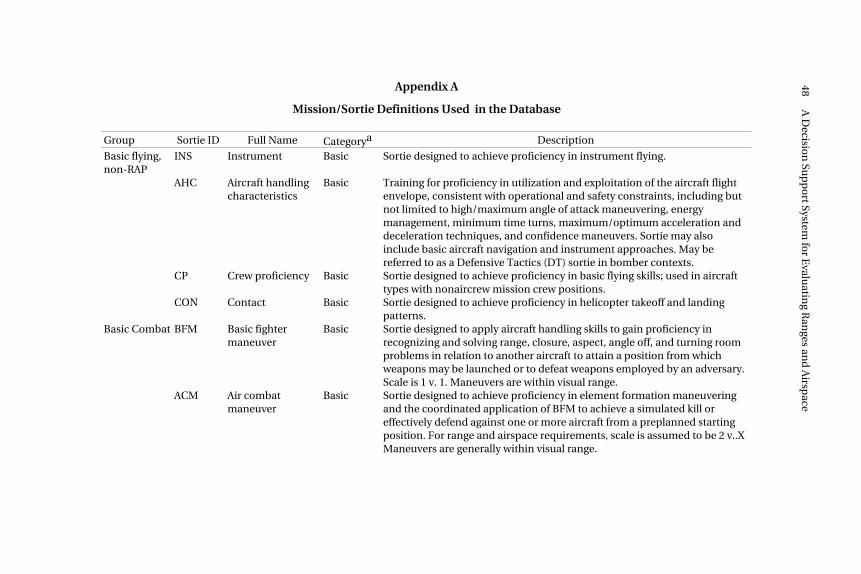
MISSION/SORTIE DEFINITIONS USEDIN THE DATABASE
Appendix A
Mission/Sortie Definitions Used in the Database
Group Sortie ID Full Name Categorya Description
Basic flying,non-RAP
INS Instrument Basic Sortie designed to achieve proficiency in instrument flying.
AHC Aircraft handlingcharacteristics
Basic Training for proficiency in utilization and exploitation of the aircraft flightenvelope, consistent with operational and safety constraints, including butnot limited to high/maximum angle of attack maneuvering, energymanagement, minimum time turns, maximum/optimum acceleration anddeceleration techniques, and confidence maneuvers. Sortie may alsoinclude basic aircraft navigation and instrument approaches. May bereferred to as a Defensive Tactics (DT) sortie in bomber contexts.
CP Crew proficiency Basic Sortie designed to achieve proficiency in basic flying skills; used in aircrafttypes with nonaircrew mission crew positions.
CON Contact Basic Sortie designed to achieve proficiency in helicopter takeoff and landingpatterns.
Basic Combat BFM Basic fightermaneuver
Basic Sortie designed to apply aircraft handling skills to gain proficiency inrecognizing and solving range, closure, aspect, angle off, and turning roomproblems in relation to another aircraft to attain a position from whichweapons may be launched or to defeat weapons employed by an adversary.Scale is 1 v. 1. Maneuvers are within visual range.
ACM Air combatmaneuver
Basic Sortie designed to achieve proficiency in element formation maneuveringand the coordinated application of BFM to achieve a simulated kill oreffectively defend against one or more aircraft from a preplanned startingposition. For range and airspace requirements, scale is assumed to be 2 v..XManeuvers are generally within visual range.
48A
Decisio
n Su
pp
ort System
for E
valuatin
g Ran
ges and
Airsp
ace
Appendix A—continued
Group Sortie ID Full Name Categorya Description
Basic Combat BSA Basic surfaceattack
Basic Sortie designed to achieve proficiency in medium/low altitude tacticalnavigation and air-to-surface weapon delivery events.
CSS Combat skillssortie
Basic Sortie designed to achieve proficiency in selected events; events areaccomplished independently (as building blocks) rather than beingintegrated in a specific combat scenario.
Fighter,air-to-air
DCA Defensive counterair
Applied Sortie designed to develop proficiency in defensive counter air tactics. Forthe purpose of determining range and airspace requirements, the sortie isassumed to be on a 4 v. X scale. Full vertical dimension is used toaccomplish tactical objectives.
OCA Offensive counterair
Applied Sortie designed to develop proficiency in air-to-air offensive counter airtactics. For the purpose of determining range and airspace requirements,the sortie is assumed to be on a 4 v. X scale. Full vertical dimension is used toaccomplish tactical objectives.
OCA ANTI- HELO
Anti-helicoptermission
Variant A-10 mission to gain proficiency in attacks against opposing helicopters.
Fighter,air-to-ground
SAT FTR Surface attacktactics (fighter)
Applied Sortie designed to develop proficiency in surface attack against a tacticaltarget; should include air or ground threat. Although not specified in AFI11-2 series publications, the sortie should include tactical navigation eventsduring ingress and egress. For the F-117, includes vertical navigation events.
SAT FTR GD OPP
SAT (fighter)ground threatopposed
Variant SAT variant using ground threat emitters to provide simulated opposition.
SAT FTR AIR OPP
SAT (fighter) airthreat Opposed
Variant SAT variant using Red Air assets to provide simulated opposition.
SAT FTR LIVE
SAT (fighter) withlive ordnance
Variant SAT sortie with delivery of live weapons.
Missio
n/So
rtie Defin
ition
s Used
in th
e Datab
ase49
Appendix A—continued
Group Sortie ID Full Name Categorya Description
Fighter,air-to-ground
SAT FTR CLASS OPS
SAT (fighter) withclassifiedoperations
Variant F-117 variant that includes operations to be performed on a classified range.
SEAD-C Suppression ofenemy air defense,conventional
Applied Sortie designed to develop proficiency in suppression of enemy air defensesusing conventional air-to-ground weapons.
SEAD Suppression ofenemy air defense
Applied Sortie designed to develop proficiency in suppression of enemy air defensesusing antiradiation weapons.
FAC-A Forward aircontrol
Applied Sortie flown to provide airborne forward air control of armed attack fightersin support of actual or simulated ground fighters.
Bomber SAT BOMB
Surface attacktactics (bomber)
Applied Sortie designed to develop proficiency in surface attacks against a tacticaltarget; should include air or ground threat. Sortie should include tacticalnavigation events during ingress and egress.
SAT BOMB INRT LO
SAT (bomber) lowaltitude
Variant SAT BOMB variant in which actual release of inert ordnance occurs from lowaltitude.
SAT BOMB INRT HI/MED
SAT (bomber)hi/mediumaltitude
Variant SAT BOMB variant in which actual release of inert ordnance occurs frommedium or high altitude.
SAT BOMB LIVE
SAT (bomber) withlive ordnance
Variant SAT sortie with delivery of live weapons.
SAT BOMB SIM
SAT (bomber)simulated release
Variant SAT BOMB variant in which release of weapons is simulated.
50A
Decisio
n Su
pp
ort System
for E
valuatin
g Ran
ges and
Airsp
ace
Appendix A—continued
Group Sortie ID Full Name Categorya Description
Bomber SAT BOMB MARI- TIME
SAT (bomber)maritime
Variant SAT BOMB variant flown to practice mining a maritime target.
Other MSN HC130
Mission,HC-130
Applied Combat scenario profile that relates to the requirements of the unit’sdesigned operational capability (DOC) statement.
MSN HC130 WATER
Mission,HC-130 over water
Variant HC-130 search-and-rescue mission variant performed over water.
MSN E8C Mission, JSTARS Applied Combat scenario profile that relates to the requirements of the unit’s DOCstatement.
MSN E8C TM
JSTARS missionwith terrainmasking
Variant JSTARS mission sortie that includes terrain masking.
MSN E8C RETRO
JSTARS missionwith retrogradeevent
Variant JSTARS mission sortie that includes a combat separation event (departurefrom orbit and rapid descent to gain airspeed).
MSN E3 Mission, AWACS Applied Combat scenario profile that relates to the requirements of the unit’s DOCstatement.
MSN EC130H
Mission, CompassCall
Applied Combat scenario profile that relates to the requirements of the unit’s DOCstatement.
MSN EC130E
Mission, ABCCC Applied Combat scenario profile that relates to the requirements of the unit’s DOCstatement.
MSN RC135
Mission, RivetJoint
Applied Combat scenario profile that relates to the requirements of the unit’s DOCstatement.
Missio
n/So
rtie Defin
ition
s Used
in th
e Datab
ase51
Appendix A—continued
Group Sortie ID Full Name Categorya Description
Other MSN U2 Mission,U-2
Applied Combat scenario profile that relates to the requirements of the unit’s DOCstatement.
MSN HH60G
Mission,HH-60G
Applied Combat scenario profile that relates to the requirements of the unit’s DOCstatement.
MSN UAV Mission,UAV
Applied Combat scenario profile that relates to the requirements of the unit’s DOCstatement.
Combined AWACS A-A
AWACS with air-to-air
Combined Sortie designed to exercise AWACS with air-to-air fighters.
AWACS EC AWACS electroniccombat
Combined Sortie designed to exercise AWACS employment in conjunction with aSEAD mission.
CSAR Combat searchand rescue
Combined Small multi-MDS exercise (SMME) that combines HH-60 MSN, SAT (F-16,A-10, F-15E), HH-130 MSN, and/or UAV MSN roles.
FP/SWEEP Force protection/sweep exercise
Combined SMME that combines OCA (F-15C, F-16, F-15E, F-22) and SAT (F-15E, F-16,F-117, A-10, B-1, B-2, B-52) roles. Targets may be on or off range.
LFE Large forceengagement
Combined Flag or other large training exercise involving multiple flights of aircrafttypes in a variety of roles; simulates the scale and complexity of actualcombat. Combines SAT, OCA, AWACS MSN, JSTARS MSN, UAV MSN,ABCCC MSN, CAS, CSAR, and/or Rivet Joint MSN roles.
aBasic sorties are building-block exercises that are used to train fundamental flying and operational skills. Applied sorties are intendedto more realistically simulate combat operations, incorporating intelligence scenarios and threat reaction events. Variants aresubdivisions of Ready Aircrew Program (RAP) sorties, constructed for this study, that differ significantly from each other in theirinfrastructure requirements. Combined sorties are structured to bring together several MDS, performing different operational roles, ina single training mission.
52A
Decisio
n Su
pp
ort System
for E
valuatin
g Ran
ges and
Airsp
ace
53
Appendix B
RANGE AND AIRSPACE CHARACTERISTICS
The following table lists the range and airspace characteristicscaptured for our analysis. As indicated, some information wascaptured only for MDS/sortie types, some only for available assets(existing ranges and airspace), and some for both requirements andavailable assets. Some characteristics are in text form (e.g.,scheduling agency), some are in numerical form (e.g., length innautical miles), and some are in binary (yes/no) form (e.g.,authorization to dispense chaff). Binary characteristics arepunctuated using a question mark in the characteristics column.Binary characteristics are interpreted as indicating if the item isrequired (in a requirements array) or authorized (in an availableassets array).
Threats are listed as a separate infrastructure type. However, threatemitters and communications jammers must be installed on a route,area, or range. In the database, threat requirements appear onlyonce in any given MDS/sortie-type requirements array. However,threat infrastructure availability is recorded for each route, maneuverarea, and range.
54 A Decision Support System for Evaluating Ranges and Airspace
Appendix B
Range and Airspace Characteristics
InfrastructureType Characteristics
Require-ments
AvailableAssets
Low-level Name/designation X
routes Reporting agency X
Scheduling agency X
Point of contact for scheduling agency X
Commercial phone for POCa X
DSN phone for POC X
Entry latitude (decimal degrees) X
Entry longitude (decimal degrees) X
Exit latitude (decimal degrees) X
Exit longitude (decimal degrees) X
Alternate entry points? X
Alternate exit points? X
Open 24 hours? X
Charted opening time X
Charted closing time X
Days per week X
Percentage of operating hours unavailable due to maintenance
X
Percentage of operating hours used by non-ACC users
Training route leads into/passes thru MOA or warning area?
X X
Name/designation of adjoining MOA or warning area
X
Maneuver Name/designation X
areas Reporting agency X
Scheduling agency X
POC for scheduling agency X
Commercial phone for POC X
DSN phone for POC X
Latitude at center (decimal degrees) X
Longitude at center (decimal degrees) X
Open 24 hours? X
Charted opening time X
Charted closing time X
Days per week X
Percentage of operating hours unavailable due to maintenance
X
Percentage of operating hours used by non-ACC users
X
Percentage of operating hours used by ACC users
X
Width X
Length X
Floor (ft) X
Floor type (AGL or mean sea level [MSL]) X
Ceiling (ft MSL) X
Minimum width (nm) X
Minimum length (nm) X
Maximum floor (ft AGL) X
Minimum ceiling (ft MSL) X
56 A Decision Support System for Evaluating Ranges and Airspace
Appendix B—continued
InfrastructureType Characteristics
Require-ments
AvailableAssets
Lowest floor for an altitude block (ft MSL) X
Highest ceiling for an altitude block (ft MSL) X
Minimum altitude block required (ft) X
Chaff? X X
Flares? X X
Over land? X X
Over water? X X
Over mountains? X X
Air-air communications? X X
Air-ground communications? X X
Datalink? X X
Adjoining orbit? X X
Name/designation of adjoining orbit X
Access to air-ground range? X X
Name/designation of adjoining range X
ACMI? X X
Supersonic operations? X X
Ranges Name/designation X
Alternate name X
Complex X
Reporting agency X
Scheduling agency X
Scheduling base X
POC for scheduling agency X
Commercial phone for POC X
DSN phone for POC X
Latitude at center (decimal degrees) X
Longitude at center (decimal degrees) X
Open 24 hours? X
Charted opening time X
Charted closing time X
Days per week X
Percentage of operating hours unavailable due to maintenance
X
Range and Airspace Characteristics 57
Appendix B—continued
InfrastructureType Characteristics
Require-ments
AvailableAssets
Percentage of operating hours used by nonACC users
X
Percentage of operating hours used by ACC users
X
Width of restricted airspace (nm) X
Length of restricted airspace (nm) X
Ceiling of restricted airspace (ft MSL) X
Width of weapon safety footprint area X
Length of weapon safety footprint area X
Restricted airspace minimum width (nm) X
Restricted airspace minimum length (nm) X
Restricted airspace minimum ceiling (ft MSL)
X
Weapon safety footprint area minimum width (nm)
X
Weapon safety footprint area minimum length (nm)
X
Conventional circles? X X
Strafe pits? X X
Strafe targets 30mm authorized? X X
Number of bomb targets scored simultaneously
X X
Lighted targets? X X
Vertical targets? X X
Tactical target array? X X
Second tactical target array separated by 30 nm from the first array?
X X
Urban target array? X X
Ordnance type (inert, live, or both) X X
Number of laser targets required X X
Number of infrared-significant (heated) targets
X X
Number of radar-significant targets X X
Scoring no drop? X X
Laser spot scoring? X X
Night scoring? X X
Scoring with 1-meter accuracy? X X
58 A Decision Support System for Evaluating Ranges and Airspace
Appendix B—continued
InfrastructureType Characteristics
Require-ments
AvailableAssets
Scoring available within 15 seconds of impact?
X X
Chaff/flare/ECM pods? X X
Illumination flares? X X
Attack heading variable by 90 degrees? X X
Secured to allow classified operations? X X
Night vision goggles? X X
Part of range over water? X X
Range control officer (RCO)? X X
Threats Number of required threat emitters X X
Multiple threat emitter? X X
FSUb area defense emitter? X X
Non-FSU threat emitter? X X
Transportable threat emitter? X X
Post-mission threat reaction debriefcapability?
X X
Reactive threat emitter system? X X
Smokey SAMs? X X
Radar jammer? X X
Communications jammer? X X
Orbits Name/designation X
Type (refueling, mission) X
Reporting agency X
Scheduling agency X
POC for scheduling agency X
Commercial phone for POC X
DSN phone for POC X
Entry latitude (decimal degrees) X
Entry longitude (decimal degrees) X
Exit latitude (decimal degrees) X
Exit longitude (decimal degrees) X
Open 24 hours? X
Charted opening time X
Charted closing time X
Range and Airspace Characteristics 59
Appendix B—continued
InfrastructureType Characteristics
Require-ments
AvailableAssets
Days per week X
Percentage of operating hours unavailable due to maintenance
X
Percentage of operating hours used by non-ACC users
X
Percentage of operating hours used by ACC users
X
Length (nm) X
Width (nm) X
Floor (ft MSL) X
Ceiling (ft AGL) X
Minimum width for refueling (nm) X
Minimum length for refueling X
Maximum floor for refueling (ft MSL) X
Minimum ceiling for refueling (ft) X
Minimum floor for refueling altitude block (ft)
X
Maximum ceiling for refueling altitude block (ft)
X
Altitude block required for refueling (ft) X
Minimum width for mission (nm) X
Minimum length for mission (nm) X
Maximum floor for mission (ft MSL) X
Minimum ceiling for mission (ft) X
Altitude block required for mission (ft) X
Percentage of the orbit/track over mountainous terrain
X X
Radiatable air-to-ground or artillery range at 90–150 nm from orbit?
X X
Direct access to Army maneuver area or air-to-ground range?
X X
Air-to-air range 60–120 nm from orbit? X X
Dedicated air-to-air frequency? X X
Dedicated air-ground frequency? X X
ABCCC training capsule? X X
JTIDS datalink needed? X X
Surveillance control datalink (SCDL)? X X
60 A Decision Support System for Evaluating Ranges and Airspace
Appendix B—continued
InfrastructureType Characteristics
Require-ments
AvailableAssets
Communications system operator training (CSOT) capability?
X X
JSTARS workstation? X X
Other Threat air-to-air fighter? X
Any air-to-air fighter? X
Any air-to-ground fighter? X
Threat air-to-ground fighters? X
Heavy bomber? X
Tanker? X
E-3 (AWACS)? X
E-8C (JSTARS)? X
EC-130H (ABCCC)? X
Ground FAC? X
Ground control intercept? X
Ground movers? X
Post-mission truth data? X
Landing zone? X
aPoint of contact.bFormer Soviet Union.
61
Appendix C
DATA LIMITATIONS
This appendix addresses known limitations in the data used for ouranalysis and embedded in the range and airspace database.Limitations exist in data regarding both requirements and currentinfrastructure.
REQUIREMENTS-RELATED DATA PROBLEMS
Sortie Requirements per Pilot
Sortie requirements per pilot, used to calculate required infrastruc-ture capacities, were derived primarily from annual RAP taskingmessages. However, RAP messages do not include demands forbasic skill sorties, such as AHC. We have largely ignored the demandfor such sorties, assuming that these skills are practiced duringsorties that are logged in other ways.
A more important problem is that the allocation of commanderoption sorties is subjective. We distributed commander optionsorties to specified sortie types in proportion to how those types arerepresented in RAP tasking messages.
The sortie definitions used for this project do not correspondprecisely to RAP sorties. First, we found it necessary to subdividecertain RAP sorties that have different infrastructure requirements,depending on how the sortie is flown. For example, we split SATsorties into air- and ground-opposed variants, which havesignificantly different airspace requirements. These variants are justfiner subdivisions of RAP sorties. We used our best judgment
62 A Decision Support System for Evaluating Ranges and Airspace
(assisted by ACC) to estimate the distribution of RAP sortierequirements among these variants.
Additionally, some sorties in our framework “collect” from multipleRAP sorties. These are designated small multiple-MDS exercise(SMME) sorties. They generally do not appear in RAP but were in-cluded in our framework to illustrate both the need for such sortiesand to capture the additional infrastructure requirements they wouldentail. An example of this is AWACS AA, which trains interactions ofair-to-air fighters with the Airborne Warning and Control System(AWACS). This sortie includes a fraction of DCA, SAT, and OCA sor-ties, but it has extra infrastructure requirements because of the needfor an adjacent AWACS orbit that is properly oriented with the attackaxis. Again, we had to use our best judgment to guess what fractionof each sortie type should train with AWACS because this require-ment is not in RAP for AWACS or fighter combat crew members.
Number of Pilots
Pilot counts, also used to compute infrastructure capacity require-ments, were based on PMAI and crew ratio data rather than actualhead counts. This is appropriate because requirements based on theproduct of a base’s PMAI and the MDS’s crew ratio should provide abetter (and more stable) average estimate of the demand for traininginfrastructure near a given base than would a head count. However,the PMAI data we used are subject to change and the crew ratiovalues we used are from multiple sources of varying reliability.Additionally, sortie counts depend on pilot experience levels, whichare currently declining. The data for experience levels are based on arecent snapshot of pilot inventory. Similarly, RPI 6 pilots add anadditional demand for training; their count is based on a snapshot ofthe actual inventory. In general, the dates for data for PMAI, crewratios, experience levels, and RPI 6 are not the same.
Adjustments to Sortie Requirements
In computing the time demand for ranges and airspace, we inflatedRAP-derived sortie counts to account for attrition (maintenance andweather cancellations), scheduling inefficiency, and noncontinua-tion training sorties (see discussion in Chapter Two). We found no
Data Limitations 63
empirical data from which to estimate these factors. The factors cur-rently embedded in the range and airspace database should bereviewed and refined, if possible.
Peaks in Demand
Demand is not uniform over a year but can vary in response to phe-nomena such as preparation for and recovery from deployment. Weassumed level demand throughout the year. However, to maintainappropriate readiness levels, sizing infrastructure supply to servicesuch peaks might be more appropriate than sizing to averagedemands.
CURRENT INFRASTRUCTURE DATA PROBLEMS
Data describing currently available infrastructure have variousproblems. Data were collected using a spreadsheet form distributedthroughout ACC. This discussion will be limited to data problemsthat were inherent in the forms (as opposed to problems with theresponses) and which as a result limit the analysis that can beperformed.
• Certain sorties, such as BFM and AHC, require block altitudes,whereas most sorties require a specific altitude range. However,the actual special-use airspace (SUA) floors are specified eitheras mean sea level (MSL) or above ground level (AGL), with thelatter being unsuitable for the evaluation of block altitudesbecause ceilings are always specified as MSL. In general, bothMSL and AGL floors should be provided, or (preferably) eitherone of these plus an average or maximum SUA ground altitude.Using the average would ignore the effect of widely varyingaltitudes over the SUA, whereas using the maximum mightdepict usable altitudes too conservatively.
• Opening/closing times and days per week are not as simple asthe form would lead one to presuppose. One issue is how to treatcases in which reported opening/closing times are “sunrise/sunset.” We replaced sunrise and sunset with 0600 and 1800,respectively, which is reasonable for training requirementsspread across an annual cycle. However, seasonal variations in
64 A Decision Support System for Evaluating Ranges and Airspace
training schedules (caused, for example, by contingencydeployments) could make our assumption invalid. Also, whenlonger hours/days can be prearranged, the instructions ought toindicate that the longest workable period be indicated. Theinformation of interest is not how much the infrastructure isopen, but how much it could be open to satisfy demand. Evenhere, workload or funding limitations would presumably limitthe maximum average period to something less than themaximum short-term open period.
• Yet another problem with opening and closing times isassociated with infrastructure (especially military routes) thatspan time zones. Specifying zulu times in all cases is probablybest.
• For routes, alternate entry and exit points are not currentlyusable in the range and airspace database because coordinateinformation is not supplied.
Composite Ranges and Areas
Ranges and airspace are often designated in sets. Elements of a setmay be used individually or combined with contiguous elements ofthe set to produce ranges and SUA with greater lateral or verticaldimensions. These composite ranges and airspace are useful fortraining in the more space-demanding scenarios. When infra-structure is locally scarce, it is important to avoid double-countingthe availability of an individual area that is part of a composite area.Most of the data supplied to us pertain to individual areas, but this isnot always the case. For instance, Davis-Monthan AFB reports a sin-gle range for the entire Goldwater complex, whereas Hill AFB reportssix separate range elements within the Utah Test and TrainingRange, designated by the restricted airspaces that cover them.
We have defined some composite areas, but our work is based onmap data and may not account for unique situations that make it dif-ficult to actually train in a composite area. For instance, some ele-ments may be under different scheduling or air traffic controlauthorities.
65
Appendix D
HARDWARE AND SOFTWARE REQUIREMENTS
HARDWARE
There are no restrictions on the hardware of the web client otherthan speed requirements specified by the user.
The web server and the computer where the Access database ismaintained have only one requirement: The hardware must be ableto run the Microsoft web server products and to have sufficient speedto accommodate the projected number of users.
SOFTWARE
Web Server
The range and airspace DSS depends on the following Microsoft(MS) software installed on the web server:
• Windows NT (server or workstation) or Windows 95 or 98operating system
• Personal Web Server (PWS) or Internet Information Server (IIS),version 4 or newer
• Microsoft Data Access Component (MDAC) version 2.
The DSS also uses a group of files located in a subdirectory on thepath inetsrv\iisadmin\website of the System or System32 directory ofthe operating system. The files contained in this subdirectory are
66 A Decision Support System for Evaluating Ranges and Airspace
• RangeAirspaceWeb.mdb (an Access database)
• usr_clave.mdb (an Access database)
• paf_acc.UDL (an MS datalink file)
• paf_acc_w.UDL (an MS datalink file)
• paf_acc_login.UDL (an MS datalink file).
These files are distributed with the DSS; however, the properties ofUDL files (location of database, in particular) must be modified forlocal application using standard operating system methods.
Finally, the DSS uses a group of files located in the web serversubdirectory on the path inetpub\wwwroot\paf_acc or wherever thatcomparable directory is located at the time of installation of the DSSon a web server. This is the subdirectory where the HypertextMarkup Language (HTML) or Active Server Pages (ASP) files reside.These files are also distributed with the DSS.
HTML editors (such as MS Frontpage Express—part of MS InternetExplorer) may be used to modify *.HTM files. However, theMS Notepad editor should be sufficient.
Web Client
Web access to the range and airspace DSS depends on any of themajor web browsers, such as MS Internet Explorer or Netscapeversion 4 or newer.
Web Database Update, Maintenance, and Queries
Microsoft Access is the application required to update databases,maintain or further develop the database, or perform queries.MS Excel may also prove useful in either preprocessing dataprovided to the database or postprocessing data retrieved from it.