Page 1
Formalisation of MOF-based Modelling Languages
A Diagrammatic Formalisation of MOF-BasedModelling Languages
Adrian Rutle1, Alessandro Rossini2, Yngve Lamo1, Uwe Wolter2
1Faculty of Engineering, Bergen University College, Norway
2Department of Informatics, University of Bergen, Norway
30 June 2009TOOLS Europe, Zurich
Page 2
Formalisation of MOF-based Modelling Languages
Introduction and Motivation
Outline
1 Introduction and MotivationMotivating Example
2 Diagram Predicate Framework (DPF)SyntaxSemantics
3 MOF-based Modelling LanguagesThe 4-Layered Modelling Architecture
4 Case-Study: Formalisation of EMF
5 Summary and Future Work
Page 3
Formalisation of MOF-based Modelling Languages
Introduction and Motivation
Model-Driven Engineering (MDE)
Primary artefacts of the software development process: models
Model: abstract specification of a software system
Usually graph-based structures
Model Transformation: generation of target models fromsource models
Model to modelModel to code
Metamodelling: specification of modelling languages
A metamodel defines abstract syntaxA model conforms to the metamodel of its language
Page 4
Formalisation of MOF-based Modelling Languages
Introduction and Motivation
MDE standards: state-of-the-art
Modelling languages
Unified Modeling Language (UML)Eclipse Modeling Framework (EMF)
Usually graph-based languages
Constraint languages
Object Constraint Language (OCL)
Usually text-based languages
Metamodelling frameworks
Meta-Object Facility (MOF)
Page 5
Formalisation of MOF-based Modelling Languages
Introduction and Motivation
MOF-based modelling hierarchy
Modelling layers Standards and examples
M3: Meta-metamodel MOF
M2: Metamodel UML language: Class, Attribute
M1: Model A UML model: Class Person with At-tributes name and address
M0: Instance An instance of Person: “OlaNordmann” living in “Sotraveien 1,Bergen”
Page 6
Formalisation of MOF-based Modelling Languages
Introduction and Motivation
(Meta)modelling challenges
Increase the expressive power of diagrammatic modelling:
Need for additional languages to define constraints
Mixture of different technical spacesDomain experts do not understand code
Formalise modelling and metamodelling:
Formalisation attempts not reflected in the standards
Constraints not reflected in the metamodelling hierarchyLack of diagrammatic formalisation
Page 7
Formalisation of MOF-based Modelling Languages
Introduction and Motivation
Remarks on terminology
Diagrammatic 6= Visual
Diagrammatic modelling: techniques targetting graph-basedstructures
Visualisation: rendering a model perceptible and intuitive forhumans
Graph-based structures: often easily visualised
Not necessarily always
Page 8
Formalisation of MOF-based Modelling Languages
Introduction and Motivation
Motivating Example
Outline
1 Introduction and MotivationMotivating Example
2 Diagram Predicate Framework (DPF)SyntaxSemantics
3 MOF-based Modelling LanguagesThe 4-Layered Modelling Architecture
4 Case-Study: Formalisation of EMF
5 Summary and Future Work
Page 9
Formalisation of MOF-based Modelling Languages
Introduction and Motivation
Motivating Example
Motivating example
Requirements
1 An employee must work for at least one department.
2 A department may have none or many employees.
Page 10
Formalisation of MOF-based Modelling Languages
Introduction and Motivation
Motivating Example
Motivating example
UML class diagram
Requirements
1 An employee must work for at least one department.
2 A department may have none or many employees.
Page 11
Formalisation of MOF-based Modelling Languages
Introduction and Motivation
Motivating Example
Motivating example
UML class diagram
Requirements
3 An employee may be enrolled in none or many projects.
Page 12
Formalisation of MOF-based Modelling Languages
Introduction and Motivation
Motivating Example
Motivating example
UML class diagram
Requirements
4 A department may control none or many projects.
5 A project must be controlled by exactly one department.
Page 13
Formalisation of MOF-based Modelling Languages
Introduction and Motivation
Motivating Example
Motivating example
UML class diagram
Requirements
6 An employee enrolled in a project must work in the controlling department.
7 A set of employees working for a controlling department must not be enrolled in
the same controlled project more than once.
Page 14
Formalisation of MOF-based Modelling Languages
Introduction and Motivation
Motivating Example
Motivating example
UML class diagram
Requirements
6 An employee enrolled in a project must work in the controlling department.
7 A set of employees working for a controlling department must not be enrolled in
the same controlled project more than once.
Page 15
Formalisation of MOF-based Modelling Languages
Introduction and Motivation
Motivating Example
Motivating example
UML class diagram OCL1 context Enrolment
2 inv rule6 : self . department .employees ->
3 includesAll (self . employee )
4 inv rule7 : Let enrolments :Set ( Enrolment )=
5 Enrolment . allInstances in
6 ( not enrolment -> exists (enr |
7 enr. project =self . project
8 and enr .department =self . department
9 and enr .employees =self . employees ))
Requirements
6 An employee enrolled in a project must work in the controlling department.
7 A set of employees working for a controlling department must not be enrolled in
the same controlled project more than once.
Page 16
Formalisation of MOF-based Modelling Languages
Introduction and Motivation
Motivating Example
Proposed solution: constraints integrated
Page 17
Formalisation of MOF-based Modelling Languages
Introduction and Motivation
Motivating Example
Our contribution
Diagrammatic modelling framework
Integration of constraints in models
Formalisation of the 4-layered modelling hierarchy
Formal description of the relationship between models atdifferent modelling levelsIntegration of constraints in metamodelling
Page 18
Formalisation of MOF-based Modelling Languages
Diagram Predicate Framework (DPF)
Outline
1 Introduction and MotivationMotivating Example
2 Diagram Predicate Framework (DPF)SyntaxSemantics
3 MOF-based Modelling LanguagesThe 4-Layered Modelling Architecture
4 Case-Study: Formalisation of EMF
5 Summary and Future Work
Page 19
Formalisation of MOF-based Modelling Languages
Diagram Predicate Framework (DPF)
Formalisation approach
Diagram Predicate Framework (DPF)
Based on category theory
Generalized sketches formalism
models: graphsconstraints: user-defined diagrammatic predicate signatures
Page 20
Formalisation of MOF-based Modelling Languages
Diagram Predicate Framework (DPF)
Syntax
Diagrammatic specification
S = (GS ,ΓS)
Page 21
Formalisation of MOF-based Modelling Languages
Diagram Predicate Framework (DPF)
Syntax
Diagrammatic specification
S = (GS ,ΓS) GS
Page 22
Formalisation of MOF-based Modelling Languages
Diagram Predicate Framework (DPF)
Syntax
Diagrammatic specification
S = (GS ,ΓS) GS
ΓS
Page 23
Formalisation of MOF-based Modelling Languages
Diagram Predicate Framework (DPF)
Syntax
Diagrammatic specification
S = (GS ,ΓS)
Σ = Π, α
GS
ΓS
Page 24
Formalisation of MOF-based Modelling Languages
Diagram Predicate Framework (DPF)
Syntax
Signature Σ
p α(p) Proposed visualisat. Intended semantics
[total] 1x // 2 A •
f // B ∀a ∈ A : |f (a)| ≥ 1
[single-
valued]1
x // 2 Af [1]// B ∀a ∈ A : |f (a)| ≤ 1
[cover] 1x // 2 A
f� ,2 B ∀b ∈ B : ∃a ∈ A | b ∈ f (a)
[inverse] 1
x
##2
y
cc A
f
''[INV] B
g
gg ∀a ∈ A , ∀b ∈ B : b ∈ f (a) iff a ∈ g(b)
[subset] 1
x
##
y
;; 2 A
f
''
g
77[⊑]
��B ∀a ∈ A : f (a) ⊆ g(a)
[jointly-
key]1
x //y
��??
?
?
?
?
?
z
��
2
4 3
Af //
g
��??
?
?
?
?
?
h
��
[JK]3
B
D C
∀a, a′ ∈ A : a 6= a′ implies f (a) 6=f (a′) or g(a) 6= g(a′) or h(a) 6= h(a′)
Page 25
Formalisation of MOF-based Modelling Languages
Diagram Predicate Framework (DPF)
Semantics
Outline
1 Introduction and MotivationMotivating Example
2 Diagram Predicate Framework (DPF)SyntaxSemantics
3 MOF-based Modelling LanguagesThe 4-Layered Modelling Architecture
4 Case-Study: Formalisation of EMF
5 Summary and Future Work
Page 26
Formalisation of MOF-based Modelling Languages
Diagram Predicate Framework (DPF)
Semantics
Semantics of a diagrammatic specification
Given by the set of its instances
An instance (I , ιI ) of S is
a graph homomorphism ιI : I → GS
i.e. elements of I typed over elements of GS
and constraints ([p], δ) in ΓS are satisfiedi.e. (I , ιs) |= ΓS
Remark
Nodes in GS : interpreted as sets
Arrows Af−→ B in GS : interpreted as
multi-valued functions f : A→ ℘(B)
ΠΓ
S
//___ GS
I
ιI
OO
Page 27
Formalisation of MOF-based Modelling Languages
MOF-based Modelling Languages
Outline
1 Introduction and MotivationMotivating Example
2 Diagram Predicate Framework (DPF)SyntaxSemantics
3 MOF-based Modelling LanguagesThe 4-Layered Modelling Architecture
4 Case-Study: Formalisation of EMF
5 Summary and Future Work
Page 28
Formalisation of MOF-based Modelling Languages
MOF-based Modelling Languages
The 4-Layered Modelling Architecture
MOF-based metamodelling hierarchy and DPF
MOF DPF
Page 29
Formalisation of MOF-based Modelling Languages
MOF-based Modelling Languages
The 4-Layered Modelling Architecture
MOF-based metamodelling hierarchy and DPF
MOF DPF
Page 30
Formalisation of MOF-based Modelling Languages
MOF-based Modelling Languages
The 4-Layered Modelling Architecture
MOF-based metamodelling hierarchy and DPF
MOF DPF
Page 31
Formalisation of MOF-based Modelling Languages
MOF-based Modelling Languages
The 4-Layered Modelling Architecture
MOF-based metamodelling hierarchy and DPF
MOF DPF
Page 32
Formalisation of MOF-based Modelling Languages
MOF-based Modelling Languages
The 4-Layered Modelling Architecture
MOF-based metamodelling hierarchy and DPF
MOF DPF
Page 33
Formalisation of MOF-based Modelling Languages
MOF-based Modelling Languages
The 4-Layered Modelling Architecture
MOF-based metamodelling hierarchy and DPF
MOF DPF
Page 34
Formalisation of MOF-based Modelling Languages
MOF-based Modelling Languages
The 4-Layered Modelling Architecture
MOF-based metamodelling hierarchy and DPF
MOF DPF
Page 35
Formalisation of MOF-based Modelling Languages
Case-Study: Formalisation of EMF
Outline
1 Introduction and MotivationMotivating Example
2 Diagram Predicate Framework (DPF)SyntaxSemantics
3 MOF-based Modelling LanguagesThe 4-Layered Modelling Architecture
4 Case-Study: Formalisation of EMF
5 Summary and Future Work
Page 36
Formalisation of MOF-based Modelling Languages
Case-Study: Formalisation of EMF
What is EMF?
Java open source framework for modelling, data integrationand code-generation
Implements Essential MOF (a subset of MOF 2.0)
Its metamodel called Ecore – to avoid confusion with MOF
Considered a low cost entry to the employment of MDE
Several MDE-tools built on EMF
Page 37
Formalisation of MOF-based Modelling Languages
Case-Study: Formalisation of EMF
Formalisation of EMF hierarchy
Ecore
conformsTo
��
Model
conformsTo
OO
Instance
conformsTo
OO
ΠEcore
ΓEEcore //______ GE
ιE
��
ΠCore
ΓMCore //______ GM
ιM
OO
I
ιI
OO
Page 38
Formalisation of MOF-based Modelling Languages
Case-Study: Formalisation of EMF
E and ιE
Page 39
Formalisation of MOF-based Modelling Languages
Case-Study: Formalisation of EMF
E and ιE
Page 40
Formalisation of MOF-based Modelling Languages
Case-Study: Formalisation of EMF
E and ιE
Page 41
Formalisation of MOF-based Modelling Languages
Case-Study: Formalisation of EMF
E and ιE
Page 42
Formalisation of MOF-based Modelling Languages
Case-Study: Formalisation of EMF
E and ιE
Page 43
Formalisation of MOF-based Modelling Languages
Summary and Future Work
Outline
1 Introduction and MotivationMotivating Example
2 Diagram Predicate Framework (DPF)SyntaxSemantics
3 MOF-based Modelling LanguagesThe 4-Layered Modelling Architecture
4 Case-Study: Formalisation of EMF
5 Summary and Future Work
Page 44
Formalisation of MOF-based Modelling Languages
Summary and Future Work
Related work
Graph theory Hartmut Ehrig et al
models: graphs and graph constraintsconformance: typing morphism
Constructive type theory Poernomo
models: terms (token models)metamodels: types (type models)correct typing insures correct models and metamodels
Algebraic specifications Boronat et al, Meseguer et al andRomero et al
models: graphs, nodes : attributed objects, arrows : referencesgraphs repr. by specs. in Membership Equational Logic (MEL)roles of metamodels: as data, as type or as theory
roles formally expressed by metamodel definition, model type,and metamodel realisation
Page 45
Formalisation of MOF-based Modelling Languages
Summary and Future Work
Summary
DPF as a formal diagrammatic specification framework
Integration of constraints in modelling
Presentation of a generic and flexible scheme for theformalisation of metamodelling
Application of the scheme to MOF modelling hierarchy
Integration of constraints in metamodelling
Formalisation of EMF hierarchy as a case-study
Page 46
Formalisation of MOF-based Modelling Languages
Summary and Future Work
Applications of DPF
Formalisation of UML, ER, Relational Data Models
Formalisation of copy-modify-merge approach to versioncontrol
Formalisation of constraint-aware model transformation rules
Page 47
Formalisation of MOF-based Modelling Languages
Summary and Future Work
Future work
Transformation of UML/OCL to DPF
Dependency between predicates
Prototype tool
Comparison to Epsilon, Fujaba etc
Real-size case study: noark (Norwegian Archive standard)
Page 48
Formalisation of MOF-based Modelling Languages
Summary and Future Work
Thank you!
Questions?
Page 49
Formalisation of MOF-based Modelling Languages
Summary and Future Work
Instances
Instances of PredicatesA semantic interpretation of a signature Σ = (Π, α) is given by amapping that assigns to each p ∈ Π a set [[p]] of graphhomomorphisms τ : O → α(p) called valid instances of p, writtenτ � p, where O may vary over all graphs.
Instance of Specification
An instance of a diagrammatic specification S = (GS ,ΓS) is agraph I together with a graph homomorphism ι : I → GS , written(I , ι), such that for each constraint (p, δ) ∈ ΓS we have ι∗ ∈ [[p]],where ι∗ : O∗ → α(p) is given by the following pullback diagram
α(p)δ
// GS
O∗δ∗
//
ι∗
OO
P.B.
I
ι
OO
Page 50
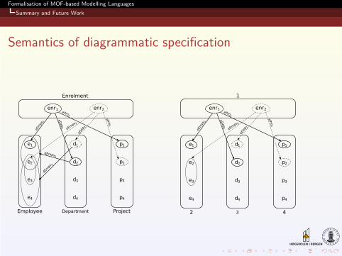
Formalisation of MOF-based Modelling Languages
Summary and Future Work
Semantics of diagrammatic specification
Page 51
Formalisation of MOF-based Modelling Languages
Summary and Future Work
Challenges in modelling
Mixing graph-based structures with textual constraintsDifferent technical spaces
checking models in two different engines/stepsmodel-constraint synchronisation problemviolation of “everything-is-a-model” vision of MDE
Challenge for domain experts who do not understand OCL
Page 52
Formalisation of MOF-based Modelling Languages
Summary and Future Work
Formalisation approach
Based on category theorySketches formalism: define semantics of diagrams (thusgraph-based models)
models: graphs (nodes and edges)model properties: universal properties (limit, colimit,commutative diagrams)
Generalized sketches formalism
not only universal propertiesuser-defined diagrammatic predicate signatures
DPF: specification formalism based on generalized sketches