IEEE TRANSACTIONS ON POWER ELECTRONICS, VOL. 31, NO. 10, OCTOBER 2016 7087
A Digital PWM Current Controller for SwitchedReluctance Motor Drives
Fei Peng, Student Member, IEEE, Jin Ye, Member, IEEE, and Ali Emadi, Fellow, IEEE
Abstract—In this paper, a PWM current controller for theswitched reluctance motor drives is proposed and digitally im-plemented. Parameter adaption is employed to guarantee both fastdynamics and robustness of the proposed current controller. Therelationship between the proposed controller and the conventionalcontrollers including PI and dead-beat controller is also presented.An improved sampling method is designed to avoid PWM delayin the control loop. Simulation and experimental results show thatthe proposed controller keeps similar dynamic response and ac-curacy as hysteresis controller under various testing conditions.However, compared with the hysteresis controller, the proposedcurrent controller needs much lower sampling rate and has a con-stant switching frequency.
Index Terms—Adaptive control, current control, motor drives,pulse width modulation (PWM), switched reluctance motor (SRM).
I. INTRODUCTION
SWITCHED reluctance motor (SRM) is an attractive alter-native to the widely used induction and synchronous ma-
chines, due to its simple and low-cost structure, high reliability,and performance at high speeds [1]. However, an SRM suffersfrom its own drawbacks due to its double-salient structure,including high-torque ripple and acoustic noise. Convention-ally, SRM is driven by asymmetric half bridges and there arethree main control methods for SRM: single pulse operation,chopping-voltage PWM, and chopping-current regulation. Sin-gle pulse operation is usually used in high-speed operation.Chopping-voltage PWM method is equivalent to reduced dcvoltage signal pulse operation. In order to reduce the torque rip-ple at low speed, chopping current regulation is generally used.
Fig. 1 shows a typical control diagram for SRM driven byasymmetric half bridges. Current controller is employed to gen-erate switching signals for the asymmetric half bridges accord-ing to the current reference. The current reference is either givenby a speed controller or a torque distributer. If the current refer-ence comes directly from a speed controller, flat top chopping
Manuscript received August 12, 2015; revised November 8, 2015; acceptedDecember 11, 2015. Date of publication December 17, 2015; date of currentversion May 20, 2016. This work was supported in part by the Canada ExcellenceResearch Chairs Program and the Natural Sciences and Engineering ResearchCouncil of Canada Discovery Grants Program. Recommended for publicationby Associate Editor Y. W. Li.
F. Peng is with the Department of Electrical and Computer Engineering,McMaster University, Hamilton, ON L8P 0A6 Canada (e-mail: [email protected]).
J. Ye and A. Emadi are with the Department of Electrical and Computer En-gineering, McMaster University, McMaster Institute for Automotive Researchand Technology, Hamilton, ON L8S 4L8 Canada (e-mail: [email protected];[email protected]).
Color versions of one or more of the figures in this paper are available onlineat http://ieeexplore.ieee.org.
Digital Object Identifier 10.1109/TPEL.2015.2510028
Fig. 1. Typical SRM control diagram.
current for each phase is employed. Due to the strong nonlin-earity, in some cases, the flat top chopping current regulationmight not provide satisfactory performance. Therefore, torquesharing control is used to distribute torque production betweentwo phases in order to produce constant torque [2]–[7].
Both flat top chopping current regulation and torque sharingcontrol rely on accurate current controllers. Hysteresis controlis one of the most popular current control schemes in SRMs,due to its fast dynamic response and model independency [4]–[8]. However, hysteresis controller also suffers from drawbacksincluding variable switching frequency and very high samplingrate [9]–[11]. Variable switching frequency in hysteresis con-trol makes it difficult to design the electromagnetic interference(EMI) filter and may cause an acoustical noise. High-speedADCs have higher sampling rate, however, they add additionalcost to the SRM drive system.
In order to avoid the drawbacks of the hysteresis currentcontroller, fixed frequency PWM controllers have been studied[9], [11]–[16]. In [12], an open loop PWM controller is used,whereas in [9], a proportional-integral (PI) current controllerhas been investigated and a current sampling method for digi-tal control have been introduced. A proportional (P) controllerwith an iterative learning control is proposed in [17] to achieveaccurate current control. In [11], [13]–[16], back EMF compen-sation to the PI current controller has been analyzed. In [11],the gains of the PI controller are adjusted according to currentand rotor position. However, a PI controller suffers from eitherslow response or possible overshot. It is also difficult to tune thePI controller in SRM applications due to the highly nonlinearcharacteristics of the machine.
Model-based dead-beat flux controller are proposed in [18]–[21]. The dead-beat controller achieves constant switching fre-quency and lower sampling rate, while maintaining the similardynamic response as hysteresis controller. However, the per-formance of a dead-beat controller relies on an accurate modeland a large gain, which may degrade the performance of thedead-beat controller.
7088 IEEE TRANSACTIONS ON POWER ELECTRONICS, VOL. 31, NO. 10, OCTOBER 2016
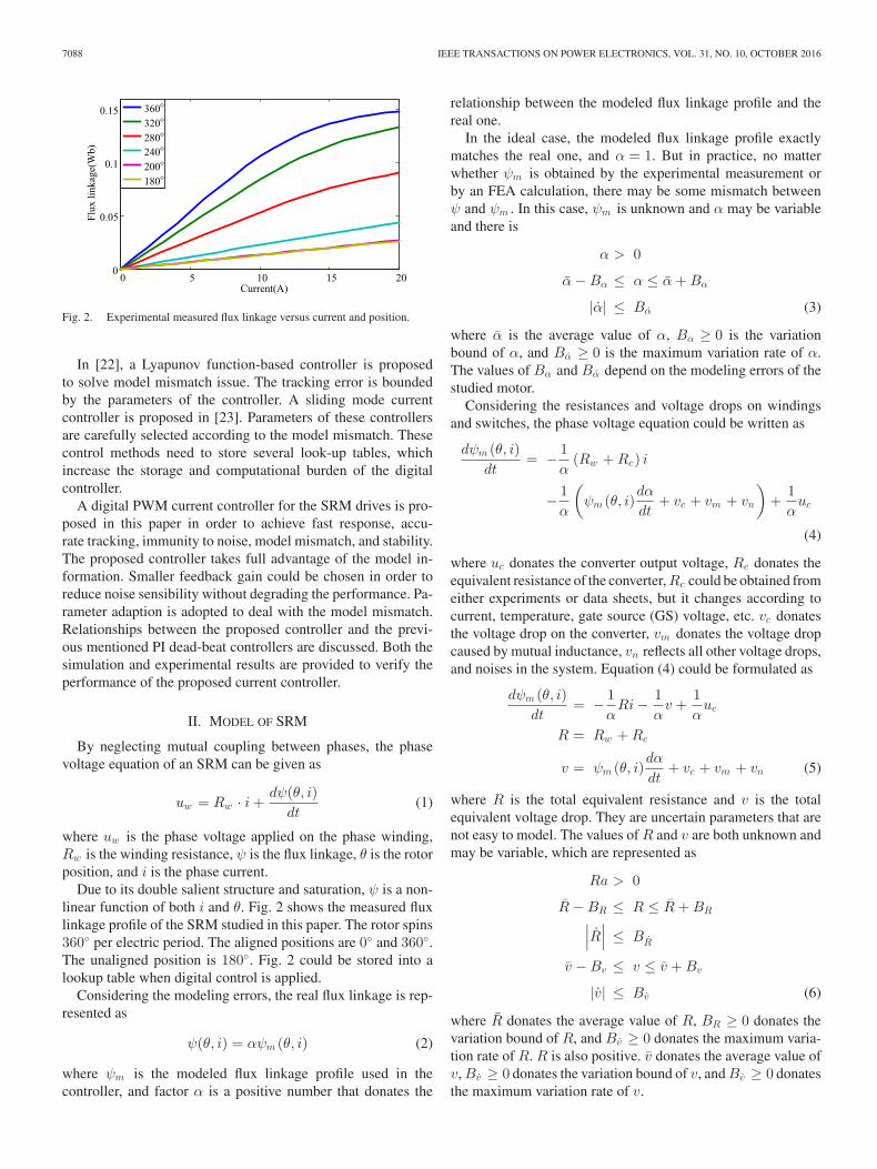
Fig. 2. Experimental measured flux linkage versus current and position.
In [22], a Lyapunov function-based controller is proposedto solve model mismatch issue. The tracking error is boundedby the parameters of the controller. A sliding mode currentcontroller is proposed in [23]. Parameters of these controllersare carefully selected according to the model mismatch. Thesecontrol methods need to store several look-up tables, whichincrease the storage and computational burden of the digitalcontroller.
A digital PWM current controller for the SRM drives is pro-posed in this paper in order to achieve fast response, accu-rate tracking, immunity to noise, model mismatch, and stability.The proposed controller takes full advantage of the model in-formation. Smaller feedback gain could be chosen in order toreduce noise sensibility without degrading the performance. Pa-rameter adaption is adopted to deal with the model mismatch.Relationships between the proposed controller and the previ-ous mentioned PI dead-beat controllers are discussed. Both thesimulation and experimental results are provided to verify theperformance of the proposed current controller.
II. MODEL OF SRM
By neglecting mutual coupling between phases, the phasevoltage equation of an SRM can be given as
uw = Rw · i +dψ(θ, i)
dt(1)
where uw is the phase voltage applied on the phase winding,Rw is the winding resistance, ψ is the flux linkage, θ is the rotorposition, and i is the phase current.
Due to its double salient structure and saturation, ψ is a non-linear function of both i and θ. Fig. 2 shows the measured fluxlinkage profile of the SRM studied in this paper. The rotor spins360◦ per electric period. The aligned positions are 0◦ and 360◦.The unaligned position is 180◦. Fig. 2 could be stored into alookup table when digital control is applied.
Considering the modeling errors, the real flux linkage is rep-resented as
ψ(θ, i) = αψm (θ, i) (2)
where ψm is the modeled flux linkage profile used in thecontroller, and factor α is a positive number that donates the
relationship between the modeled flux linkage profile and thereal one.
In the ideal case, the modeled flux linkage profile exactlymatches the real one, and α = 1. But in practice, no matterwhether ψm is obtained by the experimental measurement orby an FEA calculation, there may be some mismatch betweenψ and ψm . In this case, ψm is unknown and α may be variableand there is
α > 0
α − Bα ≤ α ≤ α + Bα
|α| ≤ Bα (3)
where α is the average value of α, Bα ≥ 0 is the variationbound of α, and Bα ≥ 0 is the maximum variation rate of α.The values of Bα and Bα depend on the modeling errors of thestudied motor.
Considering the resistances and voltage drops on windingsand switches, the phase voltage equation could be written as
dψm (θ, i)dt
= − 1α
(Rw + Rc) i
− 1α
(ψm (θ, i)
dα
dt+ vc + vm + vn
)+
1α
uc
(4)
where uc donates the converter output voltage, Rc donates theequivalent resistance of the converter, Rc could be obtained fromeither experiments or data sheets, but it changes according tocurrent, temperature, gate source (GS) voltage, etc. vc donatesthe voltage drop on the converter, vm donates the voltage dropcaused by mutual inductance, vn reflects all other voltage drops,and noises in the system. Equation (4) could be formulated as
dψm (θ, i)dt
= − 1α
Ri − 1α
v +1α
uc
R = Rw + Rc
v = ψm (θ, i)dα
dt+ vc + vm + vn (5)
where R is the total equivalent resistance and v is the totalequivalent voltage drop. They are uncertain parameters that arenot easy to model. The values of R and v are both unknown andmay be variable, which are represented as
Ra > 0
R − BR ≤ R ≤ R + BR∣∣∣R∣∣∣ ≤ BR
v − Bv ≤ v ≤ v + Bv
|v| ≤ Bv (6)
where R donates the average value of R, BR ≥ 0 donates thevariation bound of R, and Bv ≥ 0 donates the maximum varia-tion rate of R. R is also positive. v donates the average value ofv, Bv ≥ 0 donates the variation bound of v, and Bv ≥ 0 donatesthe maximum variation rate of v.
PENG et al.: DIGITAL PWM CURRENT CONTROLLER FOR SWITCHED RELUCTANCE MOTOR DRIVES 7089
III. PROPOSED CURRENT CONTROLLER
A current controller can either control the current directly orcontrol the current indirectly by controlling the flux linkage.As shown in Fig. 2, for a certain position θ, ψ is a monotoneincreasing function of i. For any i1 ≥ 0, i2 ≥ 0 there is
ψm (θ, i1) > ψm (θ, i2) ⇔ i1 > i2
ψm (θ, i1) = ψm (θ, i2) ⇔ i1 = i2
ψm (θ, i1) < ψm (θ, i2) ⇔ i1 < i2 . (7)
Therefore, the phase current can be controlled by controlling itscorresponding flux linkage. The SRM model shown in (4) con-tains unknown parameters, a current controller with estimatedparameter values could be constructed as
uc = αdψm (θ, iref )
dt+ Riref + v + ke (8)
where ψm (θ, iref ) is the reference flux linkage calculated by thereference current iref and rotor position θ, α is the estimatedvalue of α, R is the estimated value of R, v is the estimatedvalue of v, k is a positive constant, and e is the flux linkage errorwhich can be expressed as
e = ψm (θ, iref ) − ψm (θ, i). (9)
Substituting (8) into (5), the flux linkage error dynamics canbe derived as
e = − k
αe − Rei +
1α
αψm (θ, iref ) +1α
Ri +1α
v
α = α − α
R = R − R
v = v − v
ei = iref − i (10)
where α, R, and v are the estimation errors, ei is the currenterror.
If a Lyapunov candidate is selected as
V =12e2 +
12αkα
α2 +1
2αkRR2 +
12αkv
v2 (11)
where kα , kR , and kv are positive constants. Then, the derivativeof the Lyapunov candidate is
V = − k
αe2 − R
αeei
+1α
αψm (θ, iref )e −1
αkαα ˙α
+1α
Rie − 1αkR
R˙R
+1α
ve − 1αkv
v ˙v
+αα
αkα+
RR
αkR+
vv
αkv. (12)
Fig. 3. Typical waveform of ψm (θ, iref ) and iref .
It can be seen from (12) that if ˙α, ˙R, and ˙v are chosen as
˙α = kα ψm (θ, iref )e
˙R = kRie
˙v = kv e. (13)
Then, (12) becomes
V = − k
αe2 − R
αeei +
αα
αkα+
RR
αkR+
vv
αkv. (14)
A. Constant Parameters
k, R, and α are positive constants, and according to (7), ei
and e have the same sign. If α, R, v are constant, i.e.,
α = 0, R = 0, v = 0 (15)
V becomes
V = − k
αe2 − R
αeei. (16)
Therefore, V is seminegative definite. This indicates that the sys-tem is globally asymptotically stable, and e is going to convergeto zero. If e converges to zero, the system is internally stable.The convergence rate of e is determined by k and α. Since αis around 1, k could be selected to adjust the convergence rate.According to (16), a larger k gives a faster convergence rate,which means faster dynamic response. However, according to(8), k is the feedback gain of the error, in this case, a large gainmeans that the controller is more sensitive to noise. Therefore,the selection of k is a tradeoff between the dynamic responseand robustness. According to (10), if e converges to zero, forany ψm (θ, iref ) and i, there will be
αψm (θ, iref ) + Ri + v = 0. (17)
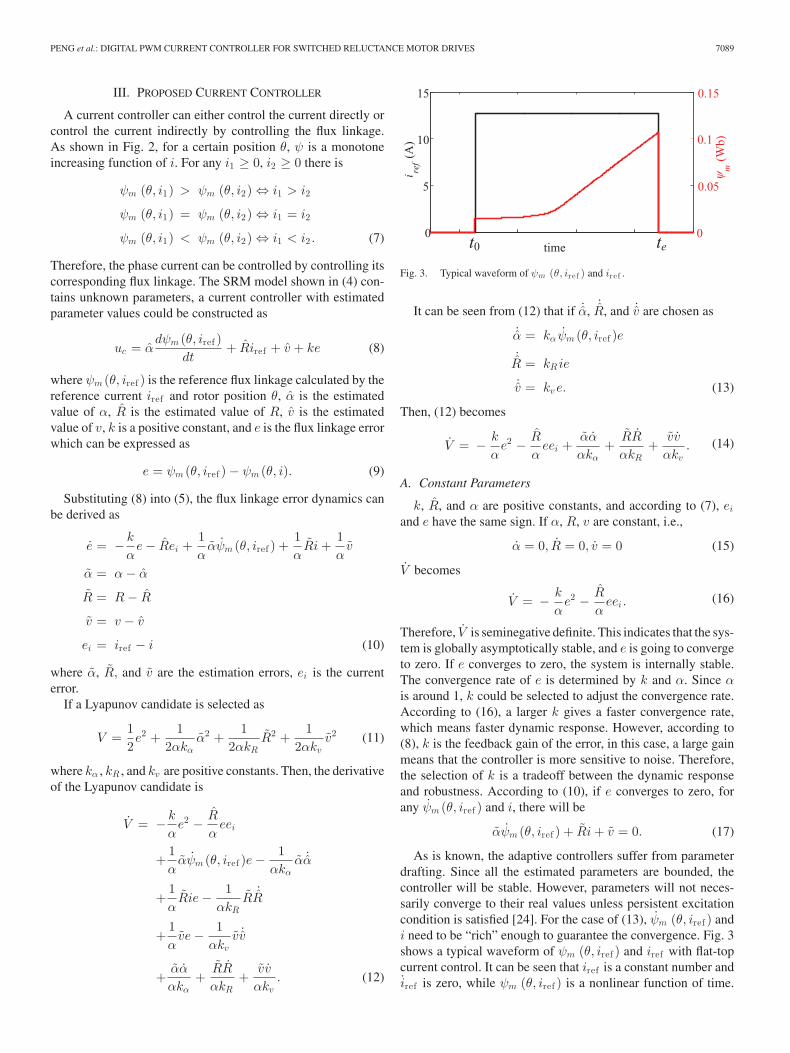
As is known, the adaptive controllers suffer from parameterdrafting. Since all the estimated parameters are bounded, thecontroller will be stable. However, parameters will not neces-sarily converge to their real values unless persistent excitationcondition is satisfied [24]. For the case of (13), ψm (θ, iref ) andi need to be “rich” enough to guarantee the convergence. Fig. 3shows a typical waveform of ψm (θ, iref ) and iref with flat-topcurrent control. It can be seen that iref is a constant number andiref is zero, while ψm (θ, iref ) is a nonlinear function of time.
7090 IEEE TRANSACTIONS ON POWER ELECTRONICS, VOL. 31, NO. 10, OCTOBER 2016
The nonlinearity of ψm (θ, iref ) will provide sufficient frequen-cies to make ψm (θ, iref ) “rich.” This is another reason why fluxlinkage is selected to be controlled instead of current. In thiscase, there is
Ψ (t) =[ψm (θ, iref , t) , 1
]T
∫ te
t0
Ψ (τ) Ψ (τ)T dτ ≥ γI (18)
where t0 is the beginning of each stroke and te is the end of thestroke. Equation (18) indicates that Ψ (t) satisfies the excitingcondition, which means
∥∥[α v
]∥∥2 is going to converge per
stoke [24]. In this case, as the controller is active each stroke,the estimation errors are going to converge to zero eventuallyand there will be
α = α
v = v. (19)
However, if the flat-top current control is applied, i may not berich enough to guarantee the convergence of R. In this case, adead zone should be added to prevent parameter drafting of R.
B. Variable Parameters
Practically, the parameters α, R, and v are not constant
α �= 0, R �= 0, v �= 0. (20)
Since α, R, and v have their own bounds, the adaption law in(13) should be modified by
(21)This modification does not affect the system stability if the realvalues of α, R, and v do not exceed their bounds. At the sametime, (22) defines the bounds of parameter estimation error
|α| ≤ 2Bα,∣∣∣R
∣∣∣ ≤ 2BR, |v| ≤ 2Bv . (22)
Combined with (3) and (6), there are
α2
2αkα+
R2
2αkR+
v2
2αkv≤ 2B2
α
αkα+
2B2R
αkR+
2B2v
αkv= M
(23)
αα
αkα+
RR
αkR+
vv
αkv≤ 2BαBα
αkα+
2BRBR
αkR+
2BvBv
αkv
= N (24)
where Bα , BR , and Bv are the bounds of α, R, and v, respec-tively. According to (14) and (11), there is
e2 = 2V − α2
αkα− R2
αkR− v2
αkv
V = −2k + kiR
α
(V − α2
2αkα− R2
2αkR− v2
2αkv
)
+αα
αkα+
RR
αkR+
vv
αkv(25)
where ki > 0 donates the relationship between e and ei . Ac-cording to (25), if V exceeds αN/2(k + kiR) + M , V will benegative, and V is going to decrease. Thus, the control error isbounded by
|e| ≤√
αN/2(k + kiR)
=
√2BαBα
(k + kiR)kα
+2BRBR
(k + kiR)kR
+2BvBv
(k + kiR)kv
.
(26)
As shown from (26), for the predefined bounds and maximumvariation rates of the unknown parameter, the control error islimited by k ,kα , kR , and kv .
IV. DIGITAL IMPLEMENTATION OF PROPOSED CURRENT
CONTROLLER
In digital implementation, the discrete form of (8) and (21)can be reformulated as
PENG et al.: DIGITAL PWM CURRENT CONTROLLER FOR SWITCHED RELUCTANCE MOTOR DRIVES 7091
Fig. 4. PWM modulation.
where T is the digital sampling time, θ(k + 1) = θ(k) + ωT ,and ω is the electric angular speed of the SRM
α (k + 1)′ = α (k) + kαΔψm (k) e (k)
α (k + 1) =
⎧⎪⎪⎨⎪⎪⎩
α (k + 1)′ , α (k + 1)′ ∈ [α − Bα, α + Bα ]
α + Bα, α (k + 1)′ > α + Bα
α − Bα, α (k + 1)′ < α − Bα
e (k)′ =
{e (k) , |e (k)| > BDZ
0, |e (k)| ≤ BDZ
R (k + 1)′ = R(k) + kR i (k) e (k) T
R (k + 1) =
⎧⎪⎪⎨⎪⎪⎩
R (k + 1)′ , R (k + 1)′ ∈[R − BR, R + BR
]R + BR, R (k + 1)′ > R + BR
R − BR, R (k + 1)′ < R − BR
v (k + 1)′ = v (k) + kv e (k) T
v (k + 1) =
⎧⎪⎪⎨⎪⎪⎩
v (k + 1)′ , v (k + 1)′ ∈ [v − Bv , v + Bv ]
v + Bv , v (k + 1)′ > v + Bv
v − Bv , v (k + 1)′ < v − Bv
(28)where Δψm (k) is defined in (27). BDZ is the error dead zone,α, R, and v are the estimated average values of α, R, and v,respectively.
A. PWM Delay Compensation
Fig. 4 shows the PWM modulation for digital control. Theduty ratio is either obtained by uc/UDC for soft chopping or0.5 + 0.5(uc/UDC ) for hard chopping. UDC is the dc bus volt-age. In the kth control period, current should be sampled att(k). But in practice, especially in a DSP control, if currentis sampled at t(k), it will take some time for the controller tocalculate the duty ratio and the duty ratio for t(k) is actuallyloaded into the PWM modulator at t(k + 1). This brings onesampling time delay into the control loop. In this case, the dutyratio for t(k) should be calculated before t(k). Mohamed andEl-Saadany [10] proposes a predictive current controller to solve
Fig. 5. Approximation of i(k), θ(k), and θ(k + 1).
the problem. However, the predictive current controller needsaccurate model and increases the calculation burden for DSP,especially for nonlinear systems such as SRMs. Blaabjerg et al.[9] recommends that current should be sampled at t(k − 1/2),which means i(k) is approximated by
i(k) ≈ i(k − 1/2). (29)
As shown in Fig. 4, there is no switching action at t(k − 1/2),EMI noise at that instance can be avoided. Furthermore, the dutyratio can be calculated within half of the period and delay in thecontrol loop is avoided.
The estimation of (29) is accurate if the average current ofeach kth period stays the same, as the (k − 1)th period shownin Fig. 4. If average current between each period changes, as thekth period shown in Fig. 4, (29) is not accurate.
As shown in Fig. 4, with the symmetrical modulation, thevoltage waveforms of the former half period and the latter halfperiod are symmetric. Therefore, the flux could be estimatedinstead of current. The flux ψm (θ(k), i(k)) could be approxi-mated by
ψm (θ(k), i(k)) ≈ 2ψm (θ(k − 1/2), i(k − 1/2))
−ψm (θ(k − 1), i(k − 1)) . (30)
In (30), current is sampled at both t(k − 1/2) and t(k − 1),which doubles the sampling rate. The ADCs used in motorcontrol is capable of working at the sampling rate of twice ofthe PWM frequency without increasing any cost. Similar to(29), (30) also avoids the EMI noise caused by the switchingaction, provides half control period for duty ratio calculation,and avoids the delay in the control loop as well.
Since the current sampling, and other calculations are per-formed at t(k − 1/2), the rotor position also has to be approx-imated with the information at t(k − 1/2). Fig. 5 shows theapproximation of ψm (θ(k), i(k)) and θ(k + 1) for further use.
B. Flux Reference Adjustment
When implemented in a digital processor, the current con-troller has to meet physical limits. Normally, when a phase isturned ON, the phase current is expected to rise quickly to thereference value, however, the voltage applied on the phase is lim-ited by UDC . It is necessary to adjust ψm (θ(k + 1), iref (k + 1))
7092 IEEE TRANSACTIONS ON POWER ELECTRONICS, VOL. 31, NO. 10, OCTOBER 2016
Therefore, ψm (θ(k + 1), iref (k + 1)) and ψm (θ(k), iref (k))in (27) should be replaced by ψadj (θ(k + 1), iref (k + 1)) andψadj (θ(k), iref (k)), respectively. Fig. 6 shows the procedure ofcalculating ψadj (θ(k + 1), iref (k + 1)) and ψadj (θ(k), iref (k))according to (31). Fig. 7 shows the procedure of calculatinge, α(k), R(k), and v(k) according to (28). Fig. 8 shows theprocedure of calculating uc(k) according to (27).
C. Relationship With Previously Proposed Controllers
As shown in Fig. 8, the controller of (27) consists of twoparts: the feedback part and the feedforward part. The feedbackpart is sensitive to noise, while the feedforward part is immuneto noise. In order to enhance the robustness of the controller,the feedforward part should give out most part of uc so that lesscontrol effort is needed by the feedback part.
The digital controller of (27) has similar form with previouslyproposed controllers. For example, all the estimated parametersare taken as its real value, and k = 1/T , then (27) becomes
where O is small enough bounded items, which could be takenas input of the error dynamic. The poles of the discrete transferfunction of (35) are
λ1,2 =
(1 − k
α T)±
√(1 − k
α T)2 − 4P
2.
(36)
To stabilize the system, the poles should be placed inside theunit cycle, and hence the limits of the parameters are
0 <k
αT < 2 + P
0 < P <14. (37)
It can be seen that in (32), k is selected to be 1/T and P isselected to be zero, and therefore, the poles are placed at zero.Due to the feedforward part in the proposed controller, a smallerk could be chosen. After k is chosen, kα , kR , and kv are selectedto ensure the stability.
V. SIMULATION AND EXPERIMENTAL RESULTS
To verify the effectiveness of the proposed current controllerfor SRM, both the simulations and experiments are conducted.The flux profile of the studied SRM is shown in Fig. 2. Otherparameters of the studied SRM are shown in Table I. To inves-tigate the performance of the proposed controller in practicalapplication, a linear torque sharing distributer is adopted to gen-erate reference current for the current controller to produce therated torque (3.2 N · m). To verify the performance of param-eter adaption, the initial value of α is set to 0.5. Parameters ofthe current controller for both simulation and experiments areshown in Table II. Center-aligned PWM and bipolar modula-tion are adopted. Parameters of the experimental plant for bothsimulation and experiments are shown in Table III.
TABLE IPARAMETERS OF THE STUDIED SRM
Parameter value
Number of stator poles 12Number of rotor poles 8Rated power 2 kWRated mechanical speed 6000 r/minRated electric speed 48 000 r/minRated Torque 3.2 N·mRated dc bus voltage 300 VWinding resistance 0.3 Ω
TABLE IIPARAMETERS OF CURRENT CONTROLLER
Parameter value
k 1000kα 100kR 100kv 10 000Initial value of α 0.5Initial value of R 0.3 ΩInitial value of v 0VBD Z 0.003α 1Bα 0.5R 0.3BR 0.2v 5Bv 5
TABLE IIIPARAMETERS OF THE EXPERIMENTAL PLANT
Symbol Parameter value
Rw SRM winding resistance 0.3 ΩRc Mosfet conduction resistance 0.1 ΩVf Diode forward voltage 0.8 Vfs Switching frequency 10 kHzT Sampling period 0.00005 sUDC DC bus voltage 300 V
A. Simulation Results
Simulation (MATLAB/Simulink) model is built to verify theeffectiveness of the proposed current controller for SRM. First,the proposed current controller is tested at low speed. TheSRM is controlled to run at an mechanical speed of 1000 r/min(8000 r/min in electric speed). Fig. 9 shows the phase currentwaveform and its reference. As a comparison, hysteresis currentcontrol with hysteresis band of ±0.5 A is applied on the sameSRM model. The sampling rate of the hysteresis controller isset to 100 kHz. Since the hysteresis controller is digitally im-plemented, one-sample-time delay is taken into account. Fig. 10shows the phase current and its reference. It is shown that theproposed current controller has almost the same dynamic re-sponse and accuracy compared with hysteresis controller. Eventhough the hysteresis current controller has a very narrow hys-teresis band and very high sampling rate, due to the finite
7094 IEEE TRANSACTIONS ON POWER ELECTRONICS, VOL. 31, NO. 10, OCTOBER 2016
Fig. 9. Phase current and its reference with proposed current controller at1000 r/min.
Fig. 10. Phase current and its reference with hysteresis current controller at1000 r/min.
Fig. 11. Calculated uc of one phase during the simulation at 1000 r/min.
sampling rate and the one-sample-time delay, the current ripplesare still larger than that of the proposed controller.
Fig. 11 shows the calculated uc by the proposed controller.It is shown that due to the nonlinearity of SRM, uc is verynonlinear. This also indicates the proposed controller has veryhigh bandwidth.
Fig. 12 shows the waveforms of control error(e), α, R, andv. It is shown that the control error is large due to the mismatchof parameters in the beginning. After the convergence of theparameters, the control error is greatly reduced.
Fig. 13 shows the results with a conventional dead-beat con-troller when α = 1, α = 1.25, and α = 0.8, respectively. It isshown that dead-beat controller is not able to track its refer-
Fig. 12. Waveforms of control error(e), α, R, and v.
Fig. 13. Phase currents and its reference with dead-beat current controller,when α = 1, α = 1.25, and α = 0.8 at 1000 r/min.
ence accurately if model mismatch occurs. Compared to theproposed current controller, the equivalent gain of dead-beatcontroller is k = 10 000, which is much larger than the gainused in the proposed controller. Larger gain indicates that thedead-beat controller is more sensitive to noise.
Then, the SRM is controlled to run at mechanical speed of6000 r/min. It has to be noted that when the mechanical speedis 6000 r/min, the electric speed of this SRM is 48 000 r/min.Normally, single pulse operation have to be applied at such highspeed, while the proposed controller still shows its effectiveness.Fig. 14 shows the phase current, current reference, the originalflux linkage reference ψm (θ, iref ), and the adjusted flux linkagereference ψadj (θ, iref ). In comparison, Fig. 15 shows the phasecurrent and its reference with hysteresis controller.
PENG et al.: DIGITAL PWM CURRENT CONTROLLER FOR SWITCHED RELUCTANCE MOTOR DRIVES 7095
Fig. 14. Phase current, current reference, the original flux linkage referenceψm (θ, iref ), and the adjusted flux linkage reference ψadj (θ, iref ) at 6000 r/min.(a) Phase current and its reference with proposed current controller at 6000 r/min.(b) Original flux linkage reference ψm (θ, iref), and the adjusted flux linkagereference ψadj (θ, iref) at 6000 r/min.
Fig. 15. Phase currents and its reference with hysteresis current controller at6000 r/min.
It is shown from Figs. 14(a) and 15 that the proposed currentcontroller also has fast dynamic response as hysteresis con-troller at higher speed. But at high speed, as shown in Fig. 15,the reference current profile for hysteresis controller have tobe modified so that the turn on angle is advanced. Otherwisethe phase current can not reach its reference. However, due toFig. 6, the reference flux is calculated in advance in the proposedcontroller. The phase winding is turned ON in advance automat-ically. Due to the limit of dc link voltage, the current can notreach its reference somewhere at high speed, but the controlleris still effective. Fig. 14(b) shows that when the calculated uc
exceeds UDC, the flux linkage reference is adjusted according toFig. 6 to keep the parameter adaption functioning.
Fig. 16. Longest possible execution time of the control algorithm.
B. Experimental Results
Experiments are designed to verify the effectiveness of theproposed current method. Fig. 17 shows the diagram of theexperimental setup. The studied SRM is controlled by a con-trol board with a DSP on it. The controller takes the referencetorque Tref , feed it into a linear torque distributer to get the ref-erence current for each phase. The proposed current controllertakes the reference current and generate switching signals to anasymmetric half bridge. The shaft of the SRM is connected witha brushless dc (BLDC) machine. The BLDC is connected witha passive rectifier. The output of the rectifier is connected witha dc/dc converter. The dc/dc converter is connected with a loadresistor. In the experiment, Tref = 3.2N · m is given into thecontroller. Load torque on the SRM is adjusted by adjusting theduty ratio of the dc/dc converter. The duty ratio is given by avariable resistor connected with the dc/dc converter. In this way,the speed of the SRM could be adjusted. Fig. 18(a) shows thestudied SRM and the BLDC load. Fig. 18(b) shows the controlboard, asymmetric half bridge for SRM, the dc/dc converter, andthe load resistor. The flux linkage profile of the studied SRM isshown in Fig. 2. Parameters of this experiment are the same asin the simulation, as shown in Tables II and III.
The SRM control algorithm, including the torque sharing andthe proposed current controller, is implemented in TI’s DSPTMS320F28335. The frequency of the DSP is 150 MHz. Thelongest possible execution time of the control algorithm withproposed current controller is shown in Fig. 16. It takes around5 μs to prepare the data of three phase current, rotor position, androtor speed. Then, at t(k − 1), it takes about 4.28 μs to calculateψm (θ(k − 1), i(k − 1)) for three phases. At t(k − 1/2), it takes17.25 μs to complete the control algorithm without any codeoptimization. If the algorithm code is further optimized, it ispossible to implement the proposed controller in popular lowcost microcontrollers in market.
First, duty ratio of the dc/dc converter is adjusted to controlthe SRM to run at mechanical speed of 1000 r/min. The proposedcurrent controller and hysteresis current controller are applied,respectively. The parameters of the two controllers are the sameas they are in the simulation. Fig. 19 shows the waveforms ofthe two current controllers. It is shown that the waveforms ob-tained in experiments matches the simulation results very much.The proposed current controller has almost the same dynamicresponse and accuracy as that of the hysteresis controller. How-ever, the proposed controller has lower current ripple and needs
7096 IEEE TRANSACTIONS ON POWER ELECTRONICS, VOL. 31, NO. 10, OCTOBER 2016
Fig. 17. Diagram of the experimental setup.
Fig. 18. Experimental setup. (a) Studied SRM and its load. (b) Digital controller and dc/dc converter.
Fig. 19. Experimental phase current (CH1), voltage (CH2) and current reference(marked by red line) waveforms at 1000 r/min. (a) Waveforms of proposedcurrent controller. (b) Waveforms of hysteresis current controller.
Fig. 20. Experimental three-phase current (CH1, CH2, CH3), torque reference (marked by red line, 2 N·m/div), and total torque production(marked by blackline, 2 N·m/div) waveforms at 1000 r/min. (a) Waveforms of proposed current controller. (b) Waveforms of hysteresis current controller.
PENG et al.: DIGITAL PWM CURRENT CONTROLLER FOR SWITCHED RELUCTANCE MOTOR DRIVES 7097
Fig. 21. Experimental phase current (CH1), voltage (CH2), and current reference(marked by red line) waveforms at 6000 r/min. (a) (a) Waveforms of proposedcurrent controller. (b) Waveforms of hysteresis current controller.
less sampling rate. Fig. 20 shows three-phase current wave-forms of the two controllers. Total torque productions by thetwo controllers are calculated from their corresponding currentwaveforms. It is shown that the reduced current ripple by theproposed current controller also results in reduced torque ripple.
Then, the SRM is controlled to run at mechanical speed of6000 r/min. The waveforms of the proposed current controllerand hysteresis current controller are shown in Fig. 21. It is shownthat the proposed current controller works well even at highspeed. The dynamic performance of the proposed controlleris also the same as of the hysteresis controller with modifiedreference current shown in Fig. 10.
The estimated parameters at 1000 r/min are α = 0.980, R =0.640, v = 1.02. When the SRM is running at 6000 r/min, thefinal estimated parameters are α = 0.969, R = 0.635, v = 1.11.The estimated parameters while running at low speed and highspeed are very close. Also they are close to the values obtained insimulation as shown in Fig. 7. This also verifies the effectivenessof the proposed controller.
VI. CONCLUSION
In this paper, a PWM current controller for SRM drives isproposed to replace the conventional hysteresis current con-troller. With parameter adaption, both fast dynamics and stabil-ity are guaranteed. Relationship between the proposed controllerand previously proposed methods is discussed. An improvedsampling method is proposed to avoid PWM delay in the con-trol loop. The proposed controller is digitally implemented andkeeps the similar dynamics and accuracy as digital hysteresiscontroller. However, the proposed current controller shows itsadvantages of lower current ripple and lower sampling rate overhysteresis controller in both the simulations and experimentsunder various testing conditions.
REFERENCES
[1] A. Emadi, Energy-Efficient Electric Motors: Selection and Applications.New York, NY, USA: Marcel Dekker, Sep. 2004.
[2] J.-W. Ahn, S.-G. Oh, J.-W. Moon, and Y.-M. Hwang, “A three-phaseswitched reluctance motor with two-phase excitation,” IEEE Trans. Ind.Appl., vol. 35, no. 5, pp. 1067–1075, Oct. 1999.
[3] J.-W. Ahn, S.-J. Park, and D.-H. Lee, “Hybrid excitation of SRM forreduction of vibration and acoustic noise,” IEEE Trans. Ind. Electron.,vol. 51, no. 2, pp. 374–380, Apr. 2004.
[4] D.-H. Lee, Z.-G. Lee, and J.-W. Ahn, “Instantaneous torque control ofSRM with a logical torque sharing method,” in Proc. IEEE Power Electron.Spec. Conf., Orlando, FL, USA, Jun. 2007, pp. 1784–1789.
[5] H. Goto, A. Nishimiya, H.-J. Guo, and O. Ichinokura, “Instantaneoustorque control using flux-based commutation and phase-torque distribu-tion technique for SR motor EV,” COMPEL: Int. J. Comput. Math. Electr.Electron. Eng., vol. 29, no. 1, pp. 173–186, Jan. 2010.
[6] J. Ye, B. Bilgin, and A. Emadi, “An extended-speed low-ripple torque con-trol of switched reluctance motor drives,” IEEE Trans. Power Electron.,vol. 30, no. 3, pp. 1457–1470, Mar. 2015.
[7] J. Ye, B. Bilgin, and A. Emadi, “An offline torque sharing function fortorque ripple reduction in switched reluctance motor drives,” IEEE Trans.Energy Convers., vol. 30, no. 2, pp. 726–735, Jun. 2015.
[8] W. Cai and F. Yi, “An integrated multiport power converter with small ca-pacitance requirement for switched reluctance motor drive,” IEEE Trans.Power Electron., vol. 31, no. 4, pp. 3016–3026, Apr. 2016.
[9] F. Blaabjerg, P. Kjaer, P. Rasmussen, and C. Cossar, “Improved digitalcurrent control methods in switched reluctance motor drives,” IEEE Trans.Power Electron., vol. 14, no. 3, pp. 563–572, May 1999.
[10] Y.-R. Mohamed and E. El-Saadany, “Robust high bandwidth discrete-time predictive current control with predictive internal ModelA unifiedapproach for voltage-source PWM converters,” IEEE Trans. Power Elec-tron., vol. 23, no. 1, pp. 126–136, Jan. 2008.
[11] S. Schulz and K. Rahman, “High-performance digital PI current regula-tor for EV switched reluctance motor drives,” IEEE Trans. Ind. Appl.,vol. 39, no. 4, pp. 1118–1126, Jul. 2003.
[12] B. Shao and A. Emadi, “A digital PWM control for switched reluctancemotor drives,” presented at the IEEE Vehicle Power Propulsion Conf.,Lille, France, Sep. 2010.
[13] R. Cardenas, R. Pena, M. Perez, J. Clare, G. Asher, and P. Wheeler, “Con-trol of a switched reluctance generator for variable-speed wind energyapplications,” IEEE Trans. Energy Convers., vol. 20, no. 4, pp. 781–791,Dec. 2005.
[14] I. Husain and M. Ehsani, “Torque ripple minimization in switched reluc-tance motor drives by PWM current control,” IEEE Trans. Power Electron.,vol. 11, no. 1, pp. 83–88, Jan. 1996.
[15] H. Vasquez and J. K. Parker, “A new simplified mathematical model fora switched reluctance motor in a variable speed pumping application,”Mechatronics, vol. 14, no. 9, pp. 1055–1068, Nov. 2004.
[16] R. Krishnan, Switched Reluctance Motor Drives: Modeling, Simulation,Analysis, Design, and Applications (Ser. Industrial Electronics) BocaRaton, FL, USA: CRC Press, 2001.
[17] S. Sahoo, S. Panda, and J. Xu, “Iterative learning-based high-performancecurrent controller for switched reluctance motors,” IEEE Trans. EnergyConvers., vol. 19, no. 3, pp. 491–498, Sep. 2004.
[18] P. Barrass and B. Mecrow, “Flux and torque control of switched reluctancemachines,” IEE Proc.-Electr. Power Appl., vol. 145, no. 6, pp. 519–527,Nov. 1998.
[19] C. Neuhaus, N. Fuengwarodsakul, and R. De Doncker, “PredictivePWM-based direct instantaneous torque control of switched reluctancedrives,” presented at the IEEEElectronics Specialists Conf., Jeju, Korea,Jun. 2006.
[20] R. Mikail, I. Husain, Y. Sozer, M. S. Islam, and T. Sebastian, “A fixedswitching frequency predictive current control method for switched reluc-tance machines,” IEEE Trans. Ind. Appl., vol. 50, no. 6, pp. 3717–3726,Nov. 2014.
7098 IEEE TRANSACTIONS ON POWER ELECTRONICS, VOL. 31, NO. 10, OCTOBER 2016
[21] F. Peng and A. Emadi, “A digital PWM current controller for switchedreluctance motor drives,” presented at theIEEE Transportation Electrifi-cation Conf. Expo., Dearborn, MI, USA, Jun. 2014.
[22] S. K. Sahoo, S. Dasgupta, S. K. Panda, and J.-X. Xu, “A lyapunov function-based robust direct torque controller for a switched reluctance motordrive system,” IEEE Trans. Power Electron., vol. 27, no. 2, pp. 555–564,Feb. 2012.
[23] J. Ye, P. Malysz, and A. Emadi, “A fixed-switching-frequency integralsliding mode current controller for switched reluctance motor drives,”IEEE J. Emerg. Sel. Topics Power Electron., vol. 3, no. 2, pp. 381–394,Jun. 2015.
[24] G. Tao, Adaptive Control Design and Analysis. New York, NY, USA:Wiley , Jul. 2003.
Fei Peng (S’15) received the B.S. and M.S. degreesin electrical engineering from Southeast University,Nanjing, China, in 2010 and 2012, respectively. Heis currently working toward the Ph.D. degree in elec-trical engineering at McMaster University, Hamilton,ON, Canada.
His research interests include optimal design andcontrol of power converters, modeling, and digitalcontrol of motor drive.
Jin Ye (S’13–M’14) received the B.S. and M.S. de-grees in electrical engineering from Xian JiaotongUniversity, Xian, China, in 2008 and 2011, respec-tively, and the Ph.D. degree in electrical engineeringfrom McMaster University, Hamilton, ON, Canada,in 2014.
She was a Postdoctoral Research Associate withthe McMaster Institute for Automotive Research andTechnology, McMaster University, Hamilton. She iscurrently an Assistant Professor of electrical engi-neering at San Francisco State University, San Fran-
cisco, CA, USA. Her main research interests include power electronics, electricmotor drives, renewable energy conversion, and electrified transportation.
Ali Emadi (S’98–M’00–SM’03–F’13) received theB.S. and M.S. degrees in electrical engineering withhighest distinction from the Sharif University ofTechnology, Tehran, Iran, in 1995 and 1997, respec-tively, and the Ph.D. degree in electrical engineeringfrom Texas A&M University, College Station, TX,USA, in 2000.
He is the Canada Excellence Research Chair inHybrid Powertrain at McMaster University, Hamil-ton, ON, Canada. Before joining McMaster Univer-sity, he was the Harris Perlstein Endowed Chair Pro-
fessor of engineering and the Director of the Electric Power and Power Elec-tronics Center and the Grainger Laboratories at Illinois Institute of Technology(IIT), Chicago, IL, USA, where he established research and teaching facilitiesas well as courses in power electronics, motor drives, and vehicular power sys-tems. He was the Founder, the Chairman, and the President of Hybrid ElectricVehicle Technologies, Inc., a University Spin-Off Company of IIT.
Dr. Emadi received numerous awards and recognitions. He was the Advisorfor the Formula Hybrid Teams at IIT and McMaster University, which wonthe GM Best Engineered Hybrid System Award at the 2010, 2013, and 2015competitions. He is the Principal author/coauthor of more than 350 journalsand conference papers, as well as several books including Vehicular ElectricPower Systems: Land, Sea, Air, and Space Vehicles (Boca Raton, FL, USA:CRC Press, 2003), Energy Efficient Electric Motors (Boca Raton, FL, USA:CRC Press, 2004), Uninterruptible Power Supplies and Active Filters (BocaRaton, FL, USA: CRC Press, 2004), Modern Electric, Hybrid Electric, andFuel Cell Vehicles (2nd ed. Boca Raton, FL, USA: CRC Press, 2009), and Inte-grated Power Electronic Converters and Digital Control (Boca Raton, FL, USA:CRC Press, 2009). He is also the Editor of the Handbook of Automotive PowerElectronics and Motor Drives (Boca Raton, FL, USA: CRC Press, 2005) andAdvanced Electric Drive Vehicles (Boca Raton, FL, USA: CRC Press, 2014). Hewas the Inaugural General Chair of the 2012 IEEE Transportation ElectrificationConference and Expo and has Chaired several IEEE and SAE conferences inthe areas of vehicle power and propulsion. He is the Founding Editor-in-Chiefof the IEEE TRANSACTIONS ON TRANSPORTATION ELECTRIFICATION.