Disputed Point as to Strength of Reanús~. A Paper read before the Victorian Institute of Engineers, on Weinesday, June 6 - by PROFESSOR KERNOT. I N THE course of a perfectly friendly but nevertheless keenly debated recent controversy with certain professional brethren as to the best way of reconstructing an old and weak bridge, my opponents condemned a proposal of mine as not possessing a sufficiently large factor of safety. As it had been my special endeavor to forestall any such criticism by making the parts in question rather stronger than usual, I was quite taken aback by the allegation. On expressing my astonishment an I perplexity, I was very courteously supplied with a copy of the calculations upon which the objection was based, and a comparison of it with my own, revealed an interesting difference in the treatment of apparently a very simple problem, leading to a surprisingly large variation in the result. As similar cases are not unlikely to occur, it seemed desirable to discuss the question fully, and therefore I submit it to the Institute. The case was that of a beam supported at the ends and loaded at the centre. The supports consisted of the top members of two large iron girders, 8 ft. apart centre to 'centre, and 18 in. in width. The top members were or massive construction, and were prevented from twisting under any Load unequal y distributed in a lateral direction, not only by their connection with the bars forming the web of the girder, but also by a series of girder irons 5.in. deep, firmly fixed to them in a transverse direction at, every 5 ft. in length, the beams in question being f laced close to each alternate girder iron. The ce tral load was imposed by a longitudinal timber 15 in.wide. In calcu'ating the strength of 4he beam my antagonists treated it as of 8 ft. span bearing an absolutely central load, and obtained the bending moment by the usual formula 4t . Now, this, to my mind placed the construction in a less favor- a n le light than it deserved ; in fact it was an extreme view on the . unfavorable side. The extreme view on the favorable side would be to regard the beam, as supported on the absolute edge of the top members, , and loaded at two point. each 7i in. from the centre, in. which case the bending I moment would be equivalent to that on a beam of 8-4-1i- or 5f_ ft. under an absolutely central load, and the strength would be greater than that on the it rmer supposition in the rates oT 8 to 51, or an excess .,f 52.4 per cent. Now, obvious that neither of these suppositions is correct, but that the truth must be somewhere between them, and how nearly it approaches the one or the other is what we want to ascertain. Assuming in the first -instance that the iron girders are rigid and incapable of twisting, it is still i mpossible for the timber beans to be supported at the extreme edge, for the timber itself will slightly compress, until the pressure is spread over an area sufficiently large to prevent further compression, idle state of hings being that shown in Fig. 2, to a greatly exaggerated scale. The
Transcript
Disputed Point as to Strength of Reanús~. A Paper read before the Victorian Institute of Engineers, on Weinesday, June 6
- by PROFESSOR KERNOT.
IN THE course of a perfectly friendly but nevertheless keenly debated recent controversy with certain professional brethren as to the best
way of reconstructing an old and weak bridge, my opponents condemned a proposal of mine as not possessing a sufficiently large factor of safety. As it had been my special endeavor to forestall any such criticism by making the parts in question rather stronger than usual, I was quite taken aback by the allegation. On expressing my astonishment an I perplexity, I was very courteously supplied with a copy of the calculations upon which the objection was based, and a comparison of it with my own, revealed an interesting difference in the treatment of apparently a very simple problem, leading to a surprisingly large variation in the result. As similar cases are not unlikely to occur, it seemed desirable to discuss the question fully, and therefore I submit it to the Institute. The case was that of a beam supported at the ends and loaded at the centre. The supports consisted of the top members of two large iron girders, 8 ft. apart centre to 'centre, and 18 in. in width. The top members were or massive construction, and were prevented from twisting under any Load unequal y distributed in a lateral direction, not only by their connection with the bars forming the web of the girder, but also by a series of girder irons 5.in. deep, firmly fixed to them in a transverse direction at, every 5 ft. in length, the beams in question being f laced close to each alternate girder iron. The ce tral load was imposed by a longitudinal timber 15 in.wide. In calcu'ating the strength of 4he beam my antagonists treated it as of 8 ft. span bearing an absolutely central load, and obtained the bending moment by the usual formula 4t. Now, this, to my mind placed the construction in a less favor-a nle light than it deserved ; in fact it was an extreme view on the. unfavorable side. The extreme view on the favorable side would be to regard the beam, as supported on the absolute edge of the top members, , and loaded at two point. each 7i in. from the centre, in. which case the bending I moment would be equivalent to that on a beam of 8-4-1i- or 5f_ ft. under an absolutely central load, and the strength would be greater than that on the
itrmer supposition in the rates oT 8 to 51, or an excess .,f 52.4 per cent. Now, obvious that neither of these suppositions is correct, but that the
truth must be somewhere between them, and how nearly it approaches the one or the other is what we want to ascertain. Assuming in the first
-instance that the iron girders are rigid and incapable of twisting, it is still impossible for the timber beans to be supported at the extreme edge, for
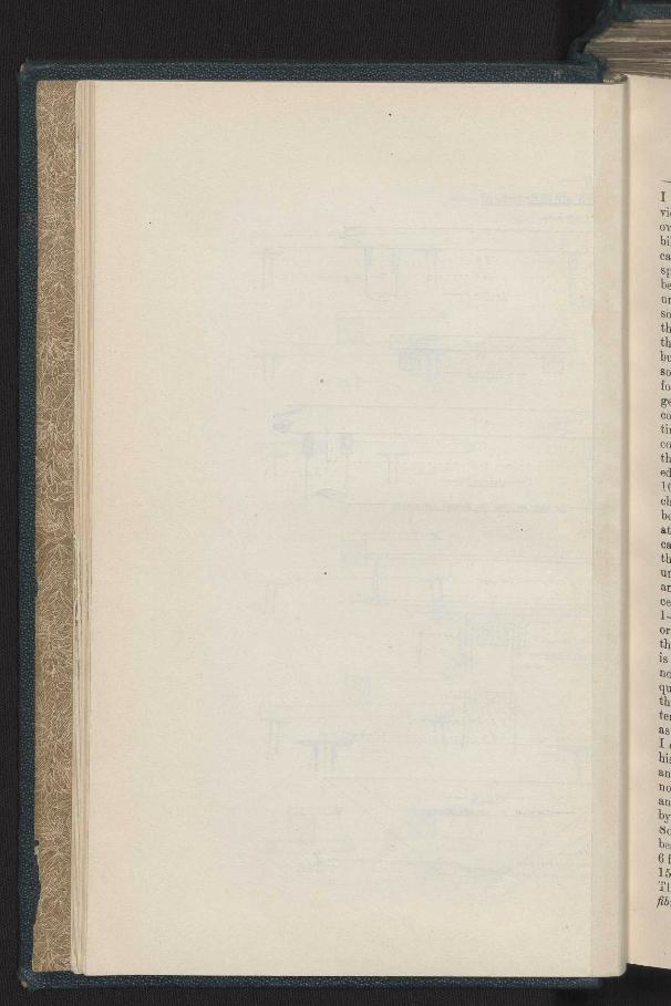
the timber itself will slightly compress, until the pressure is spread over an area sufficiently large to prevent further compression, idle state of hings being that shown in Fig. 2, to a greatly exaggerated scale. The
2 beam being 15 in'•hel wide and the load, with lull allowance for impact. being 17.4 tons •end the material requiring by my own experiments 1.5 tons per sq. inch to perceptibly indent it, and hearing in mind that the pressure will increase from zero_,at A to a maximum at B, we have 1T4 x 2=1.55 inches. As the width A B, and the centre of pressure
15'x1.5 or posit ion of the resultant will be at C, when C B== A313 —•52 inch, the
effective span becomes 6.586 feet, instead of 8 as assumed. Next, a+ to the action of the longitudinal piece 15 inches wide through which the load was imposed. The least favorable view we can take is to suppose that it exerts an equal pressure across the whole 15 inches, giving it parabolic form to the corresponding portion of the bending moment diagram, and the most favorable is that the pressure is concentrated at the extreme outside edges, causing this part of the diagram to be a horizontal straight line. Neither of these will be actually true, but the action will resemble that at the points of support, the resultant being .52 inch from the extreme edge of the beam. The case will thus become equivalent to an absolutely central load on a beam 5.423 feet span, and the strength will be greater than that obtained on the original assumption in the ratio of 8 to 5.423, or an increase of 47'5 per cent. Fig 3 shows the bending moment diagrams on the original assumption, on the most favorable assuntp•iian as above discussed, and in accordance with this final method of treatment, which is the one adopted by me, the strength of the beam being represented in the three cases by the numbers 100, 152.4. and 147.5 respectively. A further accession of strength beyond that already discussed, arises in the following way :-As flie beam deflects, its lower surface elongates, but the main girders, being tied together by the 5 inch girder irons, cannot be forced apart. Hence there is a considerable frictional impediment to the elongation of the lower surface of the beam. This will lower the neutral surface and increase the strength of the beam to an extent difficult to calculate with exactitude, but which will probably not be inconsiderallle, To verify the preceding eoticlnsious four experiments were made in the testing machine. Two of them were on models of the construction pro; osed by tue, and the other two on beams, supported on rollers at the ends, and having the load inilbsed with almost perfect centrality, * care being taken that the beam was not injured by the too, local application of the load: The two former models broke with 684 and 737 lbs. respectively, and the two latter with 477 and 483 lbs. respectively, the mean of the former two results being to that of the latter as 148 to 100, or an excess of 48 per cent. I do iiöt wish to attach undue weight to the results of these experiments, seeing that the scale was not large, and the timber used not quite the same as that proposed for the bridge. Nevertheless, I do not think it can be denied that they go far to confirm the preceding calculations, and shows that ,in any case the strength of the beams is considerably greater than would be inferred from the expression
al ,1 being taken as the
distance between the centres of the main girders.
`'luis is the regular mode of making transverse testa of timber at the University, and was devised to avoid all adventitious sources of increase of strength,
s
- c .2 — ...
\\ /
\\ ~/ --F1c.3-- ///
\ // / .
/ /
\\ /
\ /I \\\ ;
'\ / S. on 2nd assum,ot,on 6/4224,nch tbs..
on Fina/ as,um,OAon 634464,nch /b's,
4f,. / il.r.r.u_nytiontnit9 61444-61$1.
FIG. I-
tpaet, is 1.5 it the
have essnre
h, the a+ to
;h the appose ing â ornent Led at
be a it the g •5.2 ecome
i, and iption shows most final
)f the 100,
eyond beam
tied there lower
and with
verify eating sed by a, and taken load.
d the ormer of 48 these I not o not tions, erably as the
it the engtb,
J
tl
a.
si ti
''G tl Uta~ Q
o 2 b,
tc
ti w
bt
IIf
th to n~ be in dc ot
hF ca hi m en
at
A DISPUTED POINT AS TO STRENGTH OF BEAIV(S. A PAPER BY PROF. KERNOT.
Read before the Victorian Institute of Engineers on June 6, 1893.
Mr. Mountain said the Institute ought to be thankful to Professor Kernot for having brought forward this subject. For his part he thought the Professor had decidedly scored ; for given the conditions as stated in the paper he did not see how the author's antagonists could have anything to say in reply. With re4pect to the conclusions arrived at in the paper, he might point out that though the percentage of extra strength of the beam, through the actual bearing, being near the edge of the supports was very high in the short span under discussion, yet with the length of beams that engineers had usually to deal with this increase of strength was very slight, and in fact might be neglected in a beam say 20 feet long. At the same time the case of a short beam might have to be considered any day' by engineers in practice.
Mr. Ge Higgins desired to ask Professor Kernot whether the 17.4 tons was the central load on the beam or the re-action at one end.
Professor Kernot said it was central on the beam. Mr. Higgins then pointed out that in that case the Professor's calcula-
tion of the position of the centre of reaction was incorrect, as the reaction was only one-half of 17.4 tons.
Professor Kernot admitted the arithmetical error in his calculations, but pointed out that the correction only made his case the stronger, as the Bet span was still further reduced.
Mr. Higgins said that it appeared to him the whole question hinged on the absolute rigidity of the supports, for a very slight yielding indeed of the top flange of the girder would throw the centre of reaction nearertheweband make the net span of the beam conform more nearly to the actual distance between the webs of the two girders, thus reducing very considerably the increased percentage of strength claimed by Professor Kernot. He also doubted whether the bottom of a beam at the supports tended to move outwards when it was loaded.
Professor Kernot said such was undoubtedly the case. Mr. T. Timmins said that in all the beams he had observed the bottoms
had moved inwards and not outwards, and in some experiments he had carried out testing arches on iron girders supported on rollers, the roller had moved inwards to such an extent as to endanger the test; in fact in nds bridges he had watched the movements of the rollers under the free
moved inwards. Profe sor eKernot doubted doub de the accuracy of Mr. Timmins' observations
and could scarcely see how this could be the case, especially if the girder
2 A DISPUTED POINT AS TO THE STRENGTH OF BEAMS.
were cambered, for in that case the rollers must roll outwards as the girder straightened under the load.
Mr. M. Steiger supported Professor Kernot in his contention that the bottom of a girder must expand outwards under a load. It was a physical impossibility for it to do otherwise.
Mr. W. R. Rennick stated that in some tests of wooden beams which he had observed, a line was stretched between two nails driven into the beams over the supports near the bottom, for measuring the deflections by means of a scale fastened to the beams at the centre, and in oue beam the deflection was so great before the beam broke that the line sagged very much although it had originally been stretched very tightly, thus showing that the ends must have moved inwards very considerably.
Mr. H. P. C. Ashworth said that he thought the ends moved outward when the load was first applied, but that as the beaus deflected the chord of the curve of the deflected beam became shorter and when this reduction of length became greater than the extension of the bottom fibres due to tension, the ends would move inwards and continue to move inwards until the beam broke.
Mr. T. Timmins said : As I am interested in tho problem now brought forward by Professor Kernot, I should like to make a few remarks, although Imust confess that the problem appears to me to be of a remarkably simple character. I was certainly under the impression that it was capable of one solution only, but Professor Kernot surprises me with another. When I first heard of this paper I was at a loss to imagine what the Professor could have to say against such a very old practice as calculating the strength of a beam by taking the centres of the bearings as the span. For more than 20 years this hrs been my constant custom, and I believe it was universal. It is, therefore, not to be supposed that I will lightly abandon such an ancient wage without good and sound reasons. Professor Kernot's theory is opposed to ill ordinary practice as far as such practice has come under my observation ; at the same time I know that any-thing the Professor says on this subject is entitled to the greatest con-sideration and respect, and I trust that no remarks of mine will be con-sidered as a departure from such just deference. I will endeavor to show you where I consider his theory weak and where it will not bear investiga-tion. Allow me at once to strongly impress upon you one important fact, viz , that we are not dealing with a single beam, but with hundreds of beams, and the failure of any single beam would mean a catastrophe too awful to contemplate, so that no cheese-paring economy or hair-splitting calculations should be permitted to mar the absolute safety of such a vast and important structure. If the case were otherwise, and only a few seams affected, it might be possible (to parody the phrase of a great politician) to spokeshave the bottoms of the beams, and sand paper the tops of the girders, but it is doubtful whether even this would cause the beams to act as the Professor assumes. He gives two cases which he denotes as extreme views. The first is on the unfavorable side, and is WL over 4, with 8 feet span. [See sketch A.] The second is on the favorable side, and regards the beam as supported on the absolute edge of the top members, and loaded on the outer edges of the longitudinal beam as Fig. B. The truth, he says, must lie between these extreme views, but
3 girder
hat the hysical
3 which a to the ions by am the Id very , thus y. utward
chord luction due to Ls until
rought though simple of one 'hen I )fessor rength r more it was ,andon )fessor ractice 5 any- b con
con-) show stiga-t fact, ds of
ie too atting a vast a few great
T the ie the oh he and is n the ge of beam
,s, but
Ce,
7",
KERN DISCUSSION ON PROF
iBiflS
— n c B—
—Fic A
'J'
- JRf Tell 2--
/6 • • 7
15 O•
JNETCN 3-
%//c ÆWDYE.fi£ FROM PROF WARREN) CAUUC47JDNS
6.Ro//ed JorsfrS-Ó a,osr/
17
mA -
~~o r1 Pwe"
11 Cflri.il Jr:7ION 01
T6il4,NC£ of ORDER -
/2 v o
/
-^ NN ON NOTS PAPER- -Mr. T Tim 6.6. 94
t
I vo ov bil ca sp be ur SO th th bu So fo ge co tir CO th ed
ch be at ca tb ut au ce 1- or th is no qu th, ter as I, hi an n0
an by `o be; 6f 15
fib,
A DISPPTED POINT AS TO THE STRENGTH OF BEAMS. 3
I fail to see how the first or Fig. A can possibly be considered an extreme view at all. Surely Fig. E is one extreme view, with the beams bearing over a few inches on outer edges. As to Fig. B, it is a physical impossi-bility, and in no sense e.n it be considered at all. The really extreme case on the favorable side—in fact, the extreme possibility—is actually the span adopted by Professor Kernot for calculating the strength of his beams, notwithstanding the fact that there are hundreds of beams with the uneven surfaces that beams oft en have, and the impossibility of getting beams so carefully prepared as to bear at any particular spot. He adopts 1 In, as the bearing surface on the inner edges, with a maximum bearing stress across the fibres of 1. tons per square inch, in accordance with his experiments; but, surely, this is far too high a stress for any timber not perfectly dry, sound, and new. How will this be affected when the beams are green, say for the first year, and how will it fare when the beams begin to decay and get soft at the bearings. All these matters must be allowed for, and I consider that 3001bs. per square inch is the most that it is wise to put on timber at right angles to the fi re. Any greater load than this will, in the course of time, crush the fibres, and I have known many cases where even this load has caused indentations after a few years. The crushing at the edge of the flange, that is at B, on Fig. 2 of the Professor's paper, of the 1 00th of an inch, will give a bearing of 4i inches to the beam. A piece of chip or sawdust of the thickness of strong brown paper placed under the beam would completely prevent it from touching the inner edge of girder at all. The Professor assumes 1--,th beams and flanges to be mathemati-cally accurate vLi w, all know `hat a hewn or sawn beam is far from that. He takes no note of shrill; age, which is nearly always unequal and uneven, whilst it is not at all unnsaal for a b.am to have knots at the ends and shrink in the form of Fig. O. The deflection of a beam 8 feet centres at the inner edges of the girder or supports would not exceed 1-60th of an inch. Therefore, the variation of the surface of the girders or of the beams to this extent would totally annihilate Professor Kernot's theory. Any practical girder-maker knows that plates 30 years ago, which is really what we are dealing with (or even to-day for that matter) were not levelled to even -kin. and often fin. In fact I have used large quantities without levelling at all. There is no evidence show that these girders are an exception. Now had Professor Kernot had the temerity to cut off his beams with a bearing of 14in. as shown in Fig. D, as assumed in his calculations, or even with two or three times this amount, I could have understood his bringing this matter forward. Looking at his sketch Fig. 2, the beam from the end to the letter A is utterly useless, and yet it is not cut off. The only reason I can see for this is that he has no confidence in his own theory which he asks those whom he calls his antagonists to accept. At this point I beg to show you some calculations by Professor Warren in a paper read some time ago before the Royal Society of New South Wales. Sketch 1 shows a beam of 8.6in. between bearings which he calculates as 10 ft. span. Sketch 2 shows a beam of 6 ft, span which he takes as 7 ft. ; sketch 3 is 13 ft. span and taken as 15 ft. Some of these computations were checked by Professor Kernot. There is a further important point to be considered, and that is the outer fibre stress, We have nothing to do with the shape of the beam at the
4 A DISPUTED POIN1' AS TO TIIE STItENOTH Of BEAMS.
time of fracture. This is where Fig 2 is likely to be misleading. We have o ly to deal with the beam under a wt rking load, where the total deflection at centre on 8ft s;aan is not more than a tenth of an inch, nor more than 1-60th of an inch at' the edges of the flanges. These beams have to be cut to fit over cover plates and. rivet heads, and I ask you, is it possible to conceive that such work can be done by ordinary workmen in the field, with such accuracy as to preclude the possibility of any beam out of the hundreds to be fitted from taking its hearing, more or less, on the outer edge of the girder as Figs. E and F, instead of the inner edge as Fig. B. For my own part I do not believe that any engineer could be found willing to take such a risk. Next as to the twisting action on the flanges. Anyone not acquainted with the structure must accept Professor Kernot's statement that the flanges are prevented from twisting by the web and the transverse 6in. x Sin. joists. Possibly, my recent visit makes me better acquainted with the structure than the Professor. At any rate, I consider the web totally inadequate to prevent slight bucking from a lead on the edge of flange. As a matter of fact, the web in that capacity is decidedly weak. To say more would require elaborate calculations outside the scope of the present question. I fear also that he overestimates the value of. the transverse joists for prevent i ng twisting. The full size section sh' ws the joists attached by four rivets only—two on outer edge, and two 011 inner. I believe these are of an inch diameter 'L'he area would therefore be •3 of an inch. Taking both rivets as equally stressed, and load as directly vertical, the breaking load would not exceed •3 x 20 x 2 equal 12 tons. The actual load would he 8i tons. Mr. Higgins having drawn attention to the Professor having taken 17.4 tons as the reaction at one support instead of one-half this, I need not refer to it any further. It is. therefore, clear that in a very short time, even assuming the rivets perfect, they would certainly fail to carry the load to the joist, or what is very probable the heads would fly off. This would ultimately occur even if they are of an inch diameter, and they could not l ossibly be larger. Assuming they did carry the load to the joist, the flange would be bent by the joist to a different angle from the beam, so that the action of the joists would have the contrary effect to that suggested by Professor Kernot, and tend to give the beams the bearing shown in Fig. F. All that I have hitherto said refers to timber when quite new, but applies with tenfold greater force as the timber gets old. It is then specially liable to become soft, and decay at the bearings, and I ask you what would become of Professor Kernot's theory; wl:en, the beams were partially decayed at the bearings or split as they undoubtedly would. The usual fibre stress would be about 13001bs., whilst the Professor's beam has 26001bs. with 8ft. span. Now it has been found from great experience that the life of beams with 13001bs. stress is often very short—not more than 6 or 7 years, and I have recently known perfect ironbark beams utterly useless in 2 years. I therefore think it would be unwise, to say the least, to deliberately adopt beams which might by the remotest possibility be stressed Io such a figure as 2600 lbs per square inch iu such an important structure as this. As to the action of the longitudinal piece, I cannot imagine either of his extreme views. First.—Uniform bearing over whole surface. $eeund.—Bearing on outer edges. Neither cau I imagine the
re al wl tn di di in T] It th ut
by as on lal th a' as its wE m; su it nr, an «'E th, of ha tha fol lax ass fu . su at tal th1 vela op ens
gir for fro int Str 1na, as KE'
Tf
or
We total , nor earns is it to in t out t the ;e as d be L the Lssor the
ekes rate, lead y is side the
tion two
, uld and
2 ing ion ler. rets t is ven ;Tr. by
sts tnd ive old me of
:he ild;ft. ms nd rs. tpt ire
'is 3e. he
A DISPUTED POINT AS TO THE STRENGTH OF BEAMS. 5
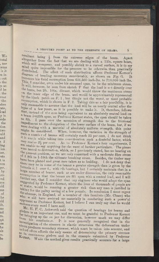
resultant being 4 from the extreme edges of the beam. Apart altogether from the fact that we are dealing with a 15in. square beam, which will compress, and possibly shrink to a curved surface, it is to my mind quite impossible for the pressure to be otherwise than practically distributed. The effect of such distribution affects Professor Kernot's diagram of bending moments considerably, as shown on Fig. G. It increases his finial assumption from 634,500 inch-lbs. to 710,000 inch lbs. This, I consider, even under his assumed span, to be the minimum stress. It will, however, be seen from sketch F that the load is net directly over the beam, but 2ft. loin. distant, which would throw the maximum stress "n the inner edge of the beam, and would be approximately represented, by the black patch on F. 1 , but thisiis not the worst, or most probable assumption, which is shown in F. 2. Taking this as a fair possibility, it is only reasonable to assume that the load will be as nearly central after the lapse of a few years, as it is possible to make it. It, therefore, follows that, instead of the esso being equivalent to an absolutely central load on a beam 5.423ft span. as Professor Kernot states, the span should be taken as 8ft. I pass over the accession of strength due to the frictional impediment to the elongation of the lower surface of the beam, but, if we were dealing with a material of absolutely uniform strength, this point 'night be considered. When, however, the variation in the strength of such a numb, r of beams will certainly reach 25 per cent, I do not think tt is worth nhiie taking into consideration such a doubtful factor, which may realise 2i per cent. As to Professor Kernot's four experiments, I am linable to say anything for the want of further particulars. The pieces were tested to destruction, which, as I previously stated, has no bearing on t he present problem, as we are only concerned with a moderate fibre stress of 1 8th to 1-10th the ultimate breaking stress. Besides, the timber "may
thave been planed and great care taken as to bedding. L do not deny that here may he in some of the beams a greater strength than ;s given by the
formula w 1 over 4., with t•ft bearings, but i certainly maintain that in a large number of beams, such as are under discussion, the only reasonable assumption is that the beams are 8ft span with a central load, and I will further say, that I consider that any engineer who would adopt the span suggested by Professor Kernot, where the lives of thousands of people are at stake, would be running a greater risk than any man is justified in tkinz for the paltry saving of a few pounds. In conclusion I must regret he absence, in England, of a member of this Institute (Mr. Chase) who
witO w uld have assisted me materially in combating such a powerrul °pponent as Professor Kernot, but I believe I can truly say that he would endorse every word I have said.
Mr g, P. C. Ashworth said the question of bearings for beams and girde1.s is an important one, and we must be grateful to Professor Kernot for bringing up the su'
l 'ect for discussion, however much we may differ
conclusioas. I*, is now generally recognised that in the nv
estigation of the stresses in elastic structures the deformation under tress Produces secondary stresses, which must be taken into account, and
ed often affords the only means of determining the primary stresses as in continuous girders and in the example submitted by Professor Kernot, While
the method gives results practically accurate for a large
6 A DISPUTED POINT AS TO THE STRENGTH OF BEAMS.
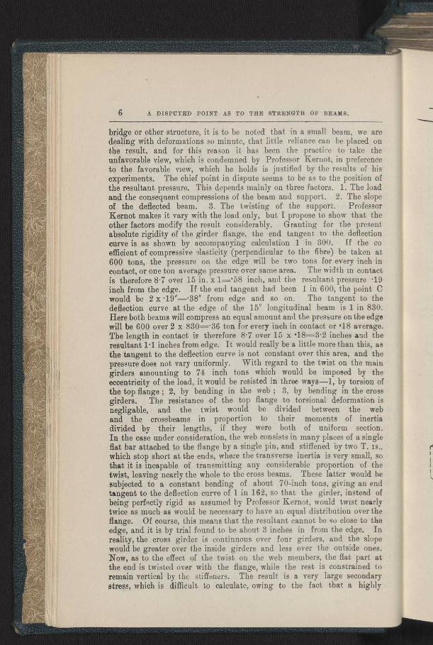
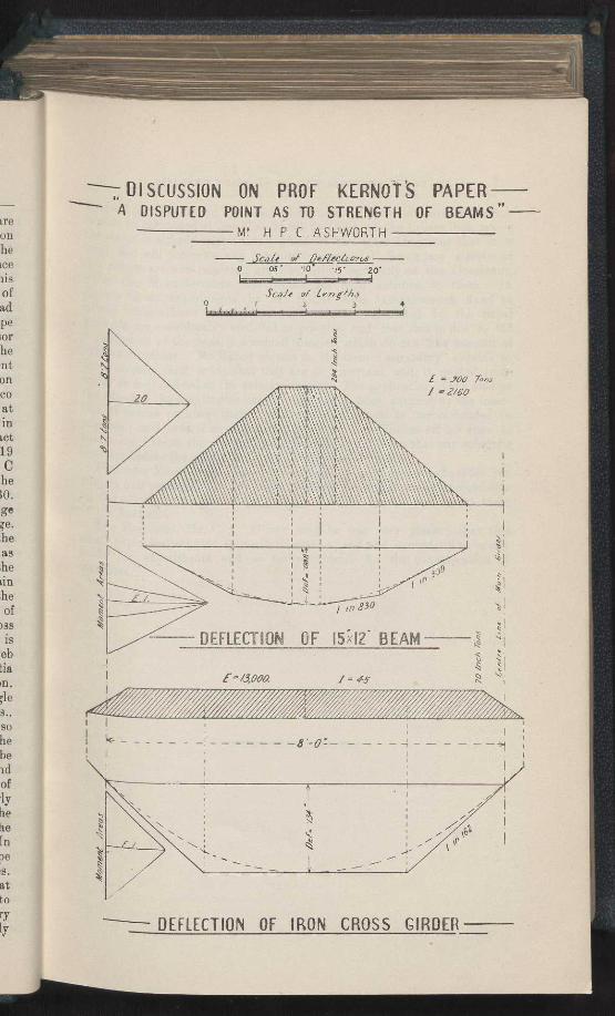
bridge or other structure, it is to be noted that in a small beam, we are dealing with deformations so minute, that little reliance can be placed on the result, and for this reason it has been the practice to take the unfavorable view, which is condemned by Professor Kernot, in preference to the favorable view, which he holds is justified by the results of his experiments. The chief point in dispute seems to be as to the position of the resultant pressure. This depends mainly on three factors. 1. The load and the consequent compressions of the beam and support. 2. The slope of the deflected beam. 3. The twisting of the support. Professor Kernot makes it vary with the load only, but I propose to show that the other factors modify the result considerably. Granting for the present absolute rigidity of the girder flange, the end tangent to the deflection curve is as shown by accompanying calculation 1 in 300. [f the co efficient of compressive 31asticity (perpendicular to the fibre) be taken at 600 tons, the pressure on the edge will be two tons for every inch in contact, or one ton average pressure over same area. The width in contact is therefore 8.7 over 15 in. x 1—.58 inch, and the resultant pressure •19 inch from the edge. If the end tangent had been 1 in 600, the point C would be 2 x .19"—•38" from edge and so on. The tangent to the deflection curve at the edge of the 15" longitudinal beam is 1 in 830. Here both beams will compress an equal amount and the pressure on the edge will be 600 over 2 x 830=•36 ton for every inch in contact or .18 average. The length in contact is therefore 8.7 over 15 x •18=3.2 inches and the resultant 1.1 inches from edge. It would really be a little more than this, as the tangent to the deflection curve is not constant over this area, and the pressure does not vary uniformly. With regard to the twist on the main girders amounting to 74 inch tons which would be imposed by the eccentricity of the load, it would be resisted in three ways-1, by torsion of the top flange ; 2, by bending in the web ; 3, by bending in the cross girders. The resistance of the top flange to torsional deformation is negligable, and the twist would be divided between the web and the crossbeams in proportion to their moments of inertia divided by their lengths, if they were both of uniform section. In the case under consideration, the web consists in many places of a single flat bar attached to the flange by a single pin, and stiffened by two T. as., which stop short at the ends, where the transverse inertia is very small, so that it is incapable of transmitting any considerable proportion of the twist, leaving nearly the whole to the cross beams. These latter would he subjected to a constant bending of about 70-inch tons, giving an end tangent to the deflection curve of 1 in 162, so that the girder, instead of being perfectly rigid as assumed by Professor Kernot, would twist nearly twice as much as would be necessary to have an equal distribution over the flange. Of course, this means that the resultant cannot be so close to the edge, and it is by trial found to be about 3 inches in from the edge. In reality, the cross girder is continuous over four girders, and the slope would be greater over the inside girders and less over the outside ones. Now, as to the effect of the twist on the web members, the flat part at the end is twisted over with the flange, while the rest is constrained to remain vertical by the stiffeners. The result is a very large secondary stress, which is difficult to calculate, owing to the fact that a highly
E _ ioo T,y
%tit ‘\\\
s 2rso
0
DEFLECTION OF I5I2' BEAM
E /3,coo !_ 45
ire
on he ~ce Di S
of ad pe for he nt on co at in ict
19 C he o. ge ;e. he as he Lin ,he of
)SS is
eb tia ~n. ;le S., so he he id of .ly he tie [n oe s. at to ry ly
- DISCUSSION ON PROF KERNOT S PAPER A DISPUTED POINT AS TO STRENGTH OF BEAMS' MP H P C ASHWORTH
Scale of ~/eflerc~cs 0 05 '10 'IS' 20*
Scale of Le7,1ths 0 2 3 4
4ma ~%!lI.IF 9' ~ ï ~iÏ
~ I~ In l~lll/I
~ I ~II II II IJI' I~~~Í ~Ì ~~~i iln.
— —8"-0:—
DEFLECTION OF IRON CROSS GIRDER
S
C
t
tl vy
a n
t t]
w
ti
ti
SI
01
S
fil
A DISPUTED POINT AS TO THE STRENGTH OF BEAMS. 7
stressed part yields and transfers the stress to another part, but which cannot be estimated at less than about five tons to the square inch, where the stress is already highest, and which is the more dangerous that it is local, and will not cause any perceptible movement. Secondary stresses of this nature are now receiving great attention, especially on the Continent, where the Moenchenstein catastrophe has been ascribed to them. In France recant experiments by M. Rabut with extensometers fixed to actual bridges have shown that the stresses calculated by the usual methods are considerably modified in practice, and that this is due to the imperfection of the usually accepted theories, which do not take account of the deformations. M. Rabut objects to the term secondary" applied to these stresses, and holds that they are as important, and, in riveted iron-work, as well defined as the primary stresses. The application of the load at the edges of the longitudinal beam might have been ensured by the inser-tion of narrow packings under them, but this cannot be recommended in practice ; and even if we grant the Professor a few inches off his span at this point, I think the preceding considerations will show that any eccentric load applied to the girder is, to say the least, inadvisable.
Professor Kernot said that he had not by any means exhausted the subject and promised that by next meeting he would make experiments on the actual movements of the ends of straight beams, and report them to the Institute.
The President, Mr. C. C. Oliver, said he was very pleased that this small paper had aroused so much discussion, and had opened up so many fields for experiments and so many subjects for the consideration of members.
i a
I
A DISPUTED POINT AS TO THE STRENGTH OF BEAMS. 9
'Mfr. Timmins wished to withdraw a remark made by him at a previous meeting, viz, "that in all beams be had observed the bottom had moved inwards and not outwards, as it had no practical bearing on the question at issue.
Professor Kernot then replied to the criticisms. He said :—My paper on the above subject read at the June meeting having aroused an unexpectedly vigorous discussion, and the scope of the debate having extended beyond the bounds of the paper, I desire to make abrief statement as to the origin of the question. The point is not primarily one of my own raising—I took no initiative. On the contrary, 1 was approached and specially invited to comment upon a certain proposal shown in Fig. 4. This I objected to as calculated to impose too large a portion of the load upon the two central girders, and so fail to utilize to the full the, in any case, scanty strength of the structure. My view on this point, I may add, is shared by several engineers of repute to whom I have submitted the question, including one very eminent American bridge engineer with whom I periodically correspond. holding this opinion I proposed three alternatives, any of which would have given a more equable distribution of load. They were all how-ever rejected, and one of them, Fig. 5, was alleged to be insufficient in strength. Hence arose the question raised by me at the June meeting. These alternative schemes, I should add, were not fully worâ ed out designs, but merely general sketches not fully detailed, and the sizes of timber were arrived at by approximate computation and comparision with existing structures. The information as to the dimensions and construction of the ironwork was taken from some tracings officially supplied several years before, duly checked . and initialled by the engineers in charge of the structure, but which differ to a rather important extent fr9m the full size section now exhibited by Mr. Timmins. Which of the two is correct I am unable to say without visiting the structure, a course so far precluded by its distance from Melbourne. In any case I cannot he blamed for using the information that had been previously supplied. With the data at my command I arrived at the dimensions of the beams in dispute, and which I ciinsidered to be rather over than under the requirements of the case. I did not for one moment imagine the design would be carried out from my rough sketches ; but anticipated that in the event of either of my schemes being adopted, a careful reconsideration of sizes with fully revised informa-t10n, and possibly an experiment upon a full or half-size beam would precede the letting of the contract. Considering that there are 262 beams concerned, I do not think the cost of the experiment could be reasonably
objected to. A. correspondence ensued which revealed the fact that the greater part of the difference of our views was due to my friends insisting en treating the load as a mathematically central one on a span measured from centre to centre of the main girders, which I made considerable allowances for the effect of breadth of bearings, but no reasons were supplied why that breadth should be ignored. A considerable time then elapsed when there being a call for papers for the Institute, I thought the point one upon which a useful discussion might be obtained, hence my paper. I desire no IV briefly
to reply to the views expressed at the June meeting. 1. The arithmetical slip detected by Mr. Higgins affects the final result to but an un-
important degree. Correcting it, the effective span becomes 5.338, instead of
/74 1l) A DISPUTED POINT AS TO THE STRENGTH OF BEAMS.
5.423 and the bending moment 624,344 ft. lbs , instead of 634,464, and the - beam becomes 12 per cent. stronger than I stated it to be. 2 . The statement
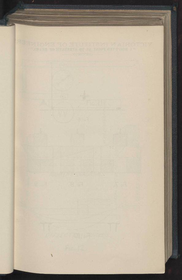
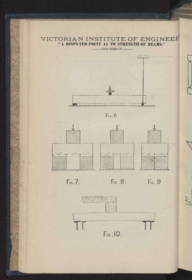
made by Messrs. Timmins and Rennick, that the ends of a beam or girder move inward when the load is imposed is diametrically opposed to all my observations and experiments as far as beams of ordinary proportions under ordinary working loads are concerned. ' But as these gentlemen have in-formed me that on reconsideration they agree with me that the motion is outward, I need say no more about it As, however, prior to hearing from them, I had prepared and brought to the Institute rooms an apparatus for experimentally demonstrating the point, it may be of interest to see the question practically tested (Exp.). With a similar but much larger and more perfect apparatus (See Fig. 6), fitted upon the testing machines at the University and having a half-inch steel roller, with an index 5 feet long, I have succeeded in very accurately measuring the outward movement of the ends of timber beams and iron girders of con-siderab'e size, and have obtained therefrom values of the modulus of elasticity agreeing very well with other determinations by more usual methods. 3. Mr. Timmins speaks of the antient and universal usage of measuring the span of a beam from the centres of the bearings. All I can say is that the practice is certainly not universal, and that I do not think it is reason-able. The Royal Commission on Railway Bridges of New South Wales, 1886, decided at an early meeting, at. which I was not present, that in the case of all non-continuous beams or girders, the clear span was to be taken as the effective span, and this instruction was carried out in almost every case. In one instance, however, through inadvertence, the span was measured to the centres of the bearings, and this instance corresponds with Mr. Timmins's " sketch 3." This particular calculation is not one of those expressly stated to have been "checked by Professor Kernot," and I have no recollection of having seen it prior to the publication of the report. As to Professor Warren's paper before the Royal Society of New South Wales, I am under no responsibility whatever. In all my own: work, as far as I can remember, I have endeavoured to use a reasonable discretion in allowing for breadth of bearing, except in cases in which the breadth of bearing was so small compared with the span as to produce no practically important difference in the result. That this is the rational, way of dealing with the question will, I think, be obvious from a consideration of extreme cases such as those shown in Figs. 7, 8, and 9. Surely no one will main-tain that the beam in Fig. 7 has an effective span of 24 inches, in Fig. 8 of 18 inches, or in Fig. 9 of 12 inches with a mathematically central load. 4. Mr. Timmins next discusses the effect of irregular bearing due to shrinkage or imperfect workmanship. See his figures C, E, and F, and dilates upon the effect of chips, sawdust, irregularity of plates and rivet heads. In reply, I would urge (1) That the comparatively high factors of safety commonly adopted, and as far as I know, justified largely by such contingencies as those mentioned. Given perfect workmanship and per-fectly uniform material, we might stress beams at least twice as much as we commonly do. But to provide for an occasional piece weaker than those we have tested, and for a possible intensification of stress arising from unfavorable conditions of workmanship, we double the sizes adopted. (2) It appears to me that Mr. Timmins' own contention that 300 lbs. per
A DISPUTED PCINT AS TO THE STRENGTH OF BEAMS. 11
id the ?ment girder 11 my under .e in-b the or to ms an terest much .sting ,h an
the con-
3ticity ;hods. uring
3 that ,anon Vales, in the taken every
was i with ne of rnd I eport. South rk. as ion in Ith of ;ically taling treme main rig. 8 load.
Me to and
rivet ors of such
I per-ch as than
rising opted. S. per
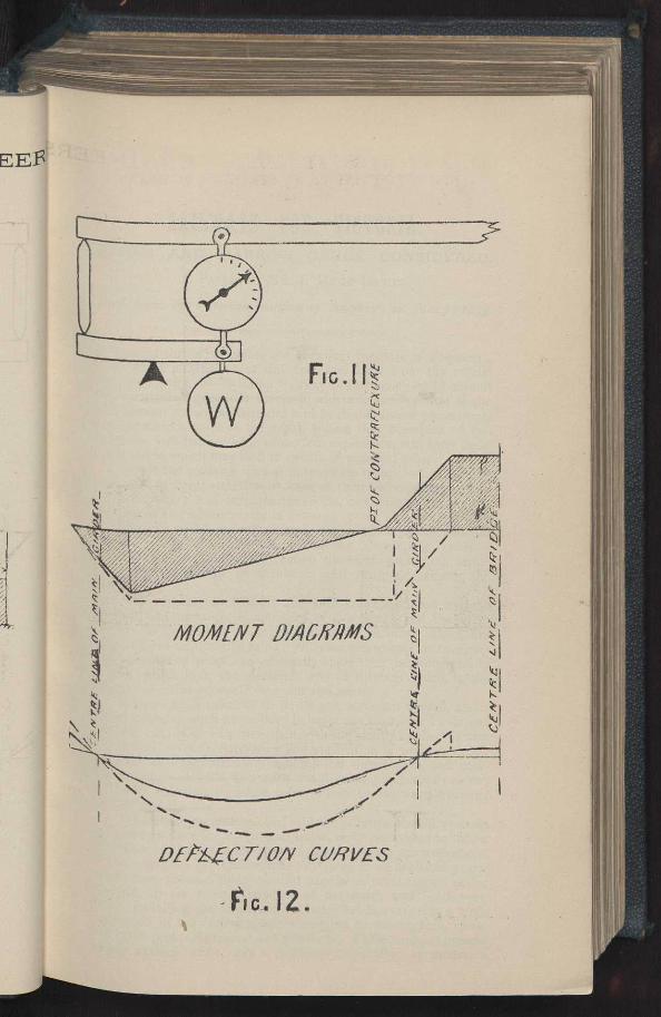
square inch is the utmost compression that hardwood timber can be expected permanently to bear across the grain, is in itself, an answer tO much that be says on this point. The only meaning I can attach to this statement, is that while new and sound timber may endure a greater pressure with increasing age it will yeild and bed itself upon a constantly augmenting area until the maximum pressure is only 300 lbs. per square Inch. Hence, the unfavorable state of things shown in Figs. C, E, and F will exist in its extreme form only while the timber is new, sound, and able to endure a high stress, but as the beam gets old and weak relief of a valuable kind and amount will be experienced. With a material capable of so bedding itself, the effect of chips, sawdust, and even rivet heads on the surfaces in contact, will be but transient. A word may now be said as to the wide discrepancy between Mr. Timmins' allowance of 300 lbs. per square inch, and mine of a ton and a half. My amount was obtained from the careful examination of a number of specimens that had been tested in the University testing-machine, while his, I understand, to have been derived from old and decaying bridges subject to the action of con-stant traffic. I am willing to admit that my figures may be too high for permanent realisation under railway conditions, but I cannot help thinking his must be too low for any material that competent inspection and main-tenance would permit to remain in use. At the same time I do not wish to be dogmatic. It is possible that an intimate acquaintance with old and worn structures may reveal results not to be anticipated from laboratory experiments. In the meantime I would suggest a compromise of half a ton per square inch, this will increase my effective span by about '4 inches making it 5.7 feet, and increasing the bending movement by about 8 per cent. (3.) My last answer to this portion of Mr. Timmins' contention is that it is quite possible, by expedients such as those shown in Fig. 10 to limit the bearings, and ensure that the points of effective support and load should not depart to any important extent from the desired positions. I should not adopt the suggestion to cut off the beams exactly at the end of the bearing (see Fig. D ) I regard the extra length as useful for purposes of attachment and also as a desirable precaution against fracture by long-itudinal or horizontal shear, a contingency involving perceptible loss of strength, which is likely to occur in short deep beams especially if there happen to be a crack or fissure in the vicinity of the neutral surface. In leaving this part of the subject I would say that Fig. 2 does not correspond with what I have observed in large beams. Fig. B is rather what 1 should expect and is much more favorable from the bending movement point of view. 5. The next point is as to the power of the flanges of the iron girders to resist twisting. In assuming that ample power of this kind ex-isted all I had touide me was the before mentioned inch to the foot sec- tion of the girders guide from an official source some years ago. This showed a compara`ively massive construction the vertical plates being 71 inches apart from centre to centre. The exact dimensions and mode of attachment of the rolled joists I had no detailed information about. I made certain reasonable assumptions from my general knowledge of ordinary practice, and amongst these the 5.8 rivets which Mr. Timmins believes to exist did certainly not occur. The usual rivets I have seen in such a situ-ation are represented by the samples submitted cut from a large bridge in
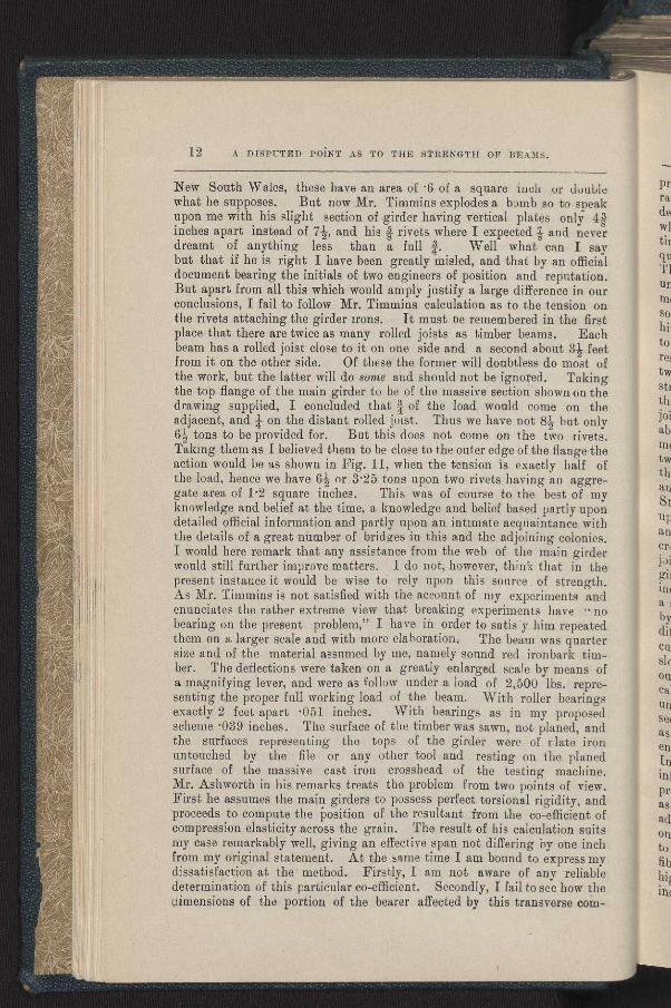
12 A DISPUTED POINT As TO THE STRENGTH OF BEAMS.
New South Wales, these have an area of •6 of a square inch or double what he supposes. But now Mr. Timmins explodes a bomb so to sneak upon me with his slight , section of girder having vertical plates only 4S inches apart instead of 72, and his â rivets where I expected $ and never dreamt of anything less than a full /. Well what can I say but that if he is right I have been greatly misled, and that by an official document bearing the initials of two engineers of position and reputation. But apart from all this which would amply justify a large difference in our conclusions, I fail to follow Mr. Timmins calculation as to the tension on the rivets attaching the girder irons. It must ce remembered in the first place that there are twice as many rolled joists as timber beams. Each beam has a rolled joist close to it on one side and a second about 3i feet from it on the other side. Of these the former will doubtless do most of the work, but the latter will do some and should not be ignored. Taking the top flange of the main girder to be of the massive section shown on the drawing supplied, I concluded that 4 of the load would come on the adjacent, and 4 on the distant rolled joist. Thus we have not 84 but only 64 tons to be provided for. But this does not come on the two rivets. Taking them as I believed them to be close to the outer edge of the flange the action would be as shown in Fig. 11, when the tension is exactly half of the load, hence we have 64 or 3.25 tons upon two rivets having an aggre- gate area of 1.2 square inches. This was of course to the best of my knowledge and belief at the time, a knowledge and belief based partly upon detailed official information and partly upon an intimate acquaintance with the details of a great number of bridges in this and the adjoining colonies. I would here remark that any assistance from the web of the main girder would still further improve matters. I do not, however, think that in the present instance it would be wise to rely upon this source of strength. As Mr. Timmins is not satisfied with the account of my experiments and enunciates the rather extreme view that breaking experiments have " no bearing on the present problem," I have in order to satis'y him repeated them on a larger scale and with more elaboration. The beam was quarter size and of the material assumed by me, namely sound red ironbark tim-ber. The deflections were taken on a greatly enlarged scale by means of a magnifying lever, and were as follow under a load of 2,500 lbs. repre-senting the proper full working load of the beam. With roller bearings exactly 2 feet apart •051 inches. With bearings as in my proposed scheme •039 inches. The surface of the timber was sawn, not planed, and the surfaces representing the tops of the girder were of r-late iron untouched by the file or any other tool and resting on the planed surface of the massive cast iron crosshead of the testing machine. Mr. Ashworth in his remarks treats the problem from two points of view. First he assumes the main girders to possess perfect torsional rigidity, and proceeds to compute the position of the resultant from the co-efficient of compression elasticity across the grain. The result of his calculation suits my case remarkably well, giving an effective span not differing by one inch from my original statement. At the same time I am bound to express my dissatisfaction at the method. Firstly, I am not aware of any reliable determination of this particular co-efficient. Secondly, I fail to see how the pimensions of the portion of the bearer affected by this transverse cow-
A DISPUTED POINT AS TO THE STRENGTH OF BEAMS. 13
ouhle speak y 8 never
say Ilicial rtion. n our n on first
Each â feet st of rking n the
the only
ivets. ;e the If of g Bre-f my upon with
mies. ;irder
the ngth. and
no
eated arter tim-ls of epre-rings Iosed and iron aned bine. view. , and nt of suits inch
1S my fable v the com-
pression are ascertained. The compression would certainly diminish very rapidly in intensity and spread over a constantly increasing area as we depart.from the surface of the beam, but how fast it would diminish and at what point it would become negligeable, I fail clearly to see. At the same time, I am willing to admit that my own treatment of this part of the question is not so scientifically complete and satisfactory as I should like. i1he problem is one to which an exact mathematical solution is perhaps unattainable but which can he solved by an approximate method within moderately narrow limits of accuracy. Next he proceeds to discuss the sources of resistance to twisting of the main girders, and here I differ from hum at almost every point. First, so far from considering the resistance to torsion of the top flange negligeable, I regard it as considerable. the result being that we have two rolled joists instead of one to resist the twisting effect of each beam. Of course the two joists will not be equally stressed but all will be stressed more or less, and my original estimate, that three-fourths only of the twisting effect comes upon the contiguous joist, cannot be far from the truth. Next I must object to his statement about the web. This in no place consists of the single "flat bar" he mentions. There is in each case a second diagonal usually consisting of t eye bars, one on each side of the compression piece. Any twisting of he
top member would modify the distribution of stress between these two arid convey a portion of the torsional moment to other parts of the girder. Still, except in the interests of general accuracy, I do not wish to dwell upon this point, as I do not consider that the web should be relied upon to any important extent for the present purpose. As to the behavior of the cross
Jousts I differ in toto ftom Mr. Ashworth. EIe has treated these Jousts as not continuous whereas they are continuous over the four main girders• Hence his moment diagram and deflection curve are seriously Incorrect. I have, endeavored to determine the true diagrams and curve by bmeth„d partly experimental, and the results are shown to scale in Fig. 12
full lines, Mr. Ashworth's being shown by dotted lines. The radical difference will be apparent at a glance, the average moment and consequent curvation being about half what Mr. Ashworth makes it, and the final slope when everything is taken into account, being about 1 in 300 on the outer, and 1 in 500 on the inner girders. To go in detail through all the calculations and investigations I have made on this point, wou'd be quite unsuitable to a meeting like the present. Suffice it to say that I do not
seeanv probability of secondary stresses being set up any more if as much as in the adopted scheme Fig. 4, in which the immediate effect of an
gine wheel on a girder as shown in Fig. E or F, may be very severe. In conclusion I desire to consider the problem in the likht of the further inform
ation elicited during the discussion. The question is, are the pr
oposed beams safe or not. Mr. Timmins says they are not and calculates follows. He takes the live load plus 40 per cent impact allowance, and
adds it to the dead load ; he considers this as a mathematically central load on the beam. He takes the span as 8 feet and assumes the supports free t'o move apart horizontally. He thus arrives by correct arithmetic at a fibres tress of 2600 lbs. per square inch, which he maintains to be undesirably high Now I diverge from him at almost every stage ; and though the individual divergences are asarule not large the aggregate result is decidedly
A DISPUTED POINT AS TO THE STRENGTH OF BEAMS.
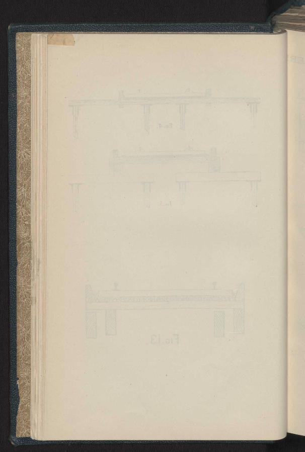
so. First from actual experience in testing bridges and taking into account the fact that the beams in question are not exposed to the direct action of the engine wheels but are sheltered so to speak, by the elasticity of the deck, and of the longitudinals I think 40 per cent rather • too high an allowance for impact. I should propose 30 per cent as quite sufficient. Second, the extra strength due to friction of the lower surface of the beam on its supports reduces the bending movement by at least 3 per cent, according to my calculations and over 5 per cent by an experiment I have made. This is not a large amount but nevertheless should not be ignored. Third, without insisting on the result of my previous calculation, but making considerable allowances for yeilding of surfaces, I still consider that it is only fair to claim a reduction of span by one foot on account of the breadth of bearing of the longitudinal beam 4. While in view of the new information relative to the construction of the top member of the main girder, I am prepared to make considerable concessions, I still must maintain that the span is not and cannot with proper construction be 8 feet. I now propose to bring the points of effective support to within 42 inches of the centre line. The effective span thus becomes 8 feet minus 9 inches minus 1 foot, or 6 feet 3 inches, or nearly a foot more than I previously estimated it. From this data I find the fibre stress to be 1494 lbs. per square inch without, and, and 1851 with the 30 per cent. impact allowance. The next question is what is the modulus of rupture of good Victorian iron bark—a number of experiments with the University testing machine upon specimens varying from 1 inch square up to 6 inches by 4 inches give from 13168 to 0704 as the value of this modulus with an appirent elastic limit of 60 per cent., while professor Warren's experiments (see Engineering construction p. 30) give 18000 for 6 in. x 4 in. beams of New South Wals ironbark,` and Mr. Whitton, late engineer in chief of New South Wales railways, obtained 13953 from a 12-inch square beam and the Royal Commission 12,200 from a beam of similar size. Adopting then Professor Lauza's method of estimating the factor of safety by com-parison with the lowest breaking stress obtained from a large number of experiments, we have a factor of 6.59 with, and 8.17 without impact allowance. Now let us compare this with factors obtained from standard colonial practice. Taking the standard 15 feet openings cf the Victorian Railways, and counting the effective span as only 13 feet, I find the fibre stress to be 1000 lbs. per square inch without impact allowance, or 1350 lbs. with 40 per cent. impact, an amount justified by the fact that the beams are directly exposed to the action of the engine wheels. Considering that many of these bridges are built of red, gum, which has a modulus of rupture of only 6648, according to experiments made in the University testing machine, the factor of safety becomes 6.65 without, or 4 94 with im-pact allowance. Thus it will be seen that these bridges which are highly approved of, and have stood the test of years, are 24 per cent, weaker than my proposed scheme—nay more if we suppose, as we reasonably may, that owing to warping or extra shrinkage either beam evades its duty as in Fig. 13, then already small factors are divided by 2, and then bridges be-come only a little more than one third as strong as my proposed beams.
* Professor Warren in" Australian Timbers" (p. 30) gives 15220 to 23406 for red ironbark, Eft. x 4ft. specimens.
Si to col Sti Cit
soa1 th, mt th, tin ex ex
p. hat ea be
tin the sn wil by bei
bol tat by en
we Of im ha( his Ne Sal tilt bol scr
Wa fil-,' for
rep AI)]
o tbo-Inc
A DISPUTED POINT AS TO THE STRENGTH OF BEAMS. 15
unt of
the an
ent. ton ing ede. ird, ing nly i of ion ain ust 3 42
12218
I
94 act iod ing by an nts ms of
im ng
of act ird an )re 50 he ng of ity
fly an nat in te-is.
ed
Similar comparisons with New South Wales practice when factors of from 5 to 6 are common with 30 to 40 per cent. impact allowance corroborate the contention that my proposed beams are over rather than under the required strength even if the effective span be taken as high as as 7 feet§ In con-clusion I claim to have shown first that in computing the strength of beams some attention should be given to and some reasonable allowance made for the effect of breadth of bearings, and second that the beams proposed by me and shown in Fig. 5, are even when a liberal allowance is made for the facts disclosed in the previous discussion, but unknown to me at the time of making proposal, stronger and not weaker than great numbers of existing bridges in this colony and New South Wales against which the experience of years has led to no complaint.
Mr, Timmin's said that in the paper Professor Kernot had stated on P. 2. that the beams were tested on rollers, and he asked was this the regu-lar mode of making transverse tests at the University and was it the custom to test beams on rollers as specified in the paper or on fixed bearings ?
Professor Kernot : It had been the practice at the University for some time in all regular tests to use rockers (as' shown on a sketch he made on the blackboard) in place of fixed bearings, and when he quoted certain re-salts as obtained by the University experiments, he meant they were taken with this apparatus The practice of using the rockers was first suggested by a number of tests on bricks for the railway department, and had since been generally adopted.
Mr. Timmins did not think that the modulus of rupture in the text books were taken from beams teste I on rollers. In America the tests were taken on fixed bearings, and as the modulus of rupture had been obtained by using these fixed bearings, he did not think that Professor Kernot was entitled to take any advantage due to this. ;Professor Kernot said the modulus of rupture obtained in his calculations
were moduli obtained by himself during tests conducted at the University. Of course, he recognised that the officers of the Railway Department had immensely greater opportunities of forming practical calculations than he had, and he, therefore, did not wish to be considered dogmatic, but -if his beams were weak, what about all those other structures and bridges in New South Wales referred to in his paper, and, moreover, their factor of safety was more precarious than ours. All his experiments led him to the conclusion that two beams were about equal to three beams when the bolts were screwed tightly, while three beams with their bolts not tightly screwed were equal to not more than two teams tightly screwed.
§ Professor Warren (Engineering Construction P. 89,) states that the New South Wales Roads and Bridges Department allow for the best ironbark a maximum fibre stress of 3,142 lbs. per squa e inch. This is 70 per cent, above my calculation for the disputed beams.
Ÿ
NoTE.— Warren Engineering Construction P. 31, proposes 13,50i as modulus of rupture of red ironbark and factor of safety of 4 for dead and 8 for live load. APPlying this ta case in paint we have 4x2.7x8x10.5=94.8 tons as pro;ter breaking
rd of the beams inqu;stion. The corresponding benoing moment betcomes on a 7 inch pounds= 163 foot tons. An almost exact agreement.
16 A DISPUTED POINT AS TO THE STRENGTH OF BEAMS.
Mr. Timmins said the Railway Department no longer used redgum. If they were using ironbark or box there could be no objection to using a higher stress, but a very low fibre stress was used in any other timbers than those he had mentioned.
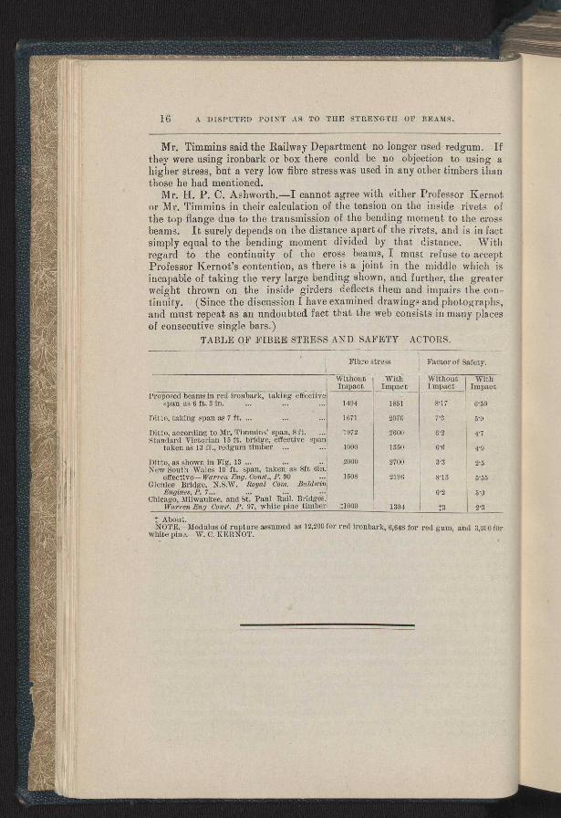
M r. H. P. C. Ashworth.—I cannot agree with either Professor Kernot or Mr. Timmins in their calculation of the tension on the inside rivets of the top flange due to the transmission of the bending moment to the cross beams. It surely depends on the distance apart of the rivets, and is in fact simply equal to the bending moment divided by that distance. With regard to the continuity of the cross beams, I must refuse to accept Professor Kernot's contention, as there is a joint in the middle which is incapable of taking the very large bending shown, and further, the greater weight thrown on the inside girders deflects them and impairs the con-tinuity. (Since the discussion I have examined drawings and photographs, and mast repeat as an undoubted fact that the web consists in many places of consecutive single bars.)
TABLE OF FIBRE STRESS AND SAFETY ACTORS.
Fibre stress Factor of Safety.
Without Impact
With Impact
Without Impact
With Impact
Proposed beams in red ironbark, taking effective span as 6 ft. 3 In.... 1494 1851 817 6.59
Ditto, taking span as 7 ft. ... ... ... 1671 2070 7.3 ,•n
Ditto, according to. Mr. Timmins' span, 8 ft. ... ìtandard Victorian 15 ft. bridge, effective span
taken as 13 ft., redgum timber ... ...
1972
1000
2600
1350
6.2 4.7
6.6 4.9
Ditto, as shown in Fig. 13 ... .. .. 2000 2700 3.3 2.5 New South Wales 10 ft. span, taken as 8ft bin.
effective—Warren Eng. Const., R 90 1508 2196 8.13 5's3 Ilenlee Bridge, N.S.W. Royal Com. Baldwin
Engines, P. 7... .. ••• - 6.2 5.0 ;hicago, Milwaukee, and St. Paul Raft. Bridges,
Warren Eng Cons', P. 97, white pine timber :1000 1304 I3 2.3 About.
NOTE.—Modulus of rupture assumed as 12,200 for red ironbark, 6,648 for red gum, and 3,000fOr white pino.—W. C. KERNOT.
A DISPUTED POINT Ais TO THE STRENGTH OF DEANS. 17
If DECEMBEB 12TH, 1894.
g a Professor Kernot said he would like to make a few remarks with refer-
han ence to the discussion which took place two months ago on Mr. Timmin's remarks on " Strength of Beams." He said that since then they
rnot had had an opportunity of seeing the structure and he would like to say a
of few words in the interests of accuracy. In the first place the section of
ross the top bar of the girder given by Mr. Timmins was correct, and the official
fact information was incorrect, and that had a rather important bearing on the
Title subject. He had relied on the official document which he now found was
sept incorrect. With reference to the transverse girder irons Mr. Timmins had
is mentioned ein. rivets and he had thought tin. ridiculous and that Bin. was
ater the correct size : he now foundthey were hot}, wrong, as they were bolts.
tbe weakness of the bolts, his beams should be increased lin. exactly. With reference to what Mr. Ashworth had spoken about with regard to certain diagonals with a single flat bar. They had found no such case ; a second diagonal went on each side of the compression piece, and examina-ion showed it as he had described, with few exceptions. Mr. Ashworth had also mentioned the joint in the middle of the crossbeams. They had
acs _ examined it and, found it a very good one, mad not weak, and very little i inferior in strength and rigidity to the intact original sectibn of the
girder iron.
But the bolts were so weak and badly spaced, that they were no better phs, than Mr. Timmins rivets, and that affected his calculations. In view of aces