16
Pneumatic Rotary Actuators and Accessories CONTROLS A Division of A-T Controls, Inc.
Pneumatic Rotary Actuatorsand Accessories
CONTROLSA Division of A-T Controls, Inc.

RACK & PINIONFEATURES
Double acting and spring return
Dual travel stops
Torques to 36,000 in.lbs.
DA and SR common end caps
ISO 5211 mounting dimensions
Wide base for direct mount to many butterfly valves
Substantial pinion bearings mean high cycle life
Corrosion resistant hard anodized finish
Each unit serialized and bar coded
Namur accessory mounting configuration
Custom accessory mounting
2
TRIAC pneumatic actuators are designed and manufactured to provide the highest cycle-life on the market. We can accessorize them to accomplish virtually any control requirement. They are available with various mounting dimension configurations and span eleven models for appropriate torque compatibility. Our extensive inventory and engineering capabilities allow us to respond to your needs with flexibility. We pride ourselves on exceeding customer expectations. Contact us for application assistance.
See accessory page for details
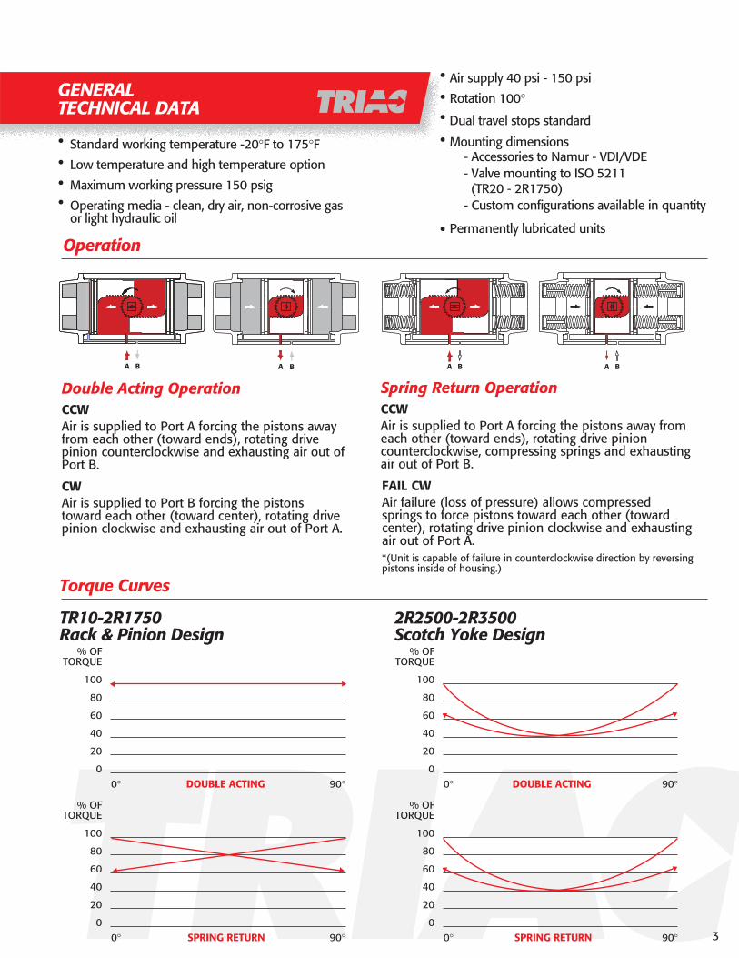
GENERALTECHNICAL DATA
Standard working temperature -20°F to 175°FLow temperature and high temperature option
Maximum working pressure 150 psig
Operating media - clean, dry air, non-corrosive gas or light hydraulic oil
Dual travel stops standard
Mounting dimensions
Permanently lubricated units
- Accessories to Namur - VDI/VDE- Valve mounting to ISO 5211 (TR20 - 2R1750)- Custom configurations available in quantity
Torque Curves
Operation
••
••
••
•
••
Double Acting OperationCCWAir is supplied to Port A forcing the pistons away from each other (toward ends), rotating drive pinion counterclockwise and exhausting air out of Port B.
CWAir is supplied to Port B forcing the pistons toward each other (toward center), rotating drive pinion clockwise and exhausting air out of Port A.
Spring Return OperationCCWAir is supplied to Port A forcing the pistons away from each other (toward ends), rotating drive pinion counterclockwise, compressing springs and exhausting air out of Port B.
FAIL CWAir failure (loss of pressure) allows compressed springs to force pistons toward each other (toward center), rotating drive pinion clockwise and exhausting air out of Port A.*(Unit is capable of failure in counterclockwise direction by reversing pistons inside of housing.)
TR10-2R1750Rack & Pinion Design
% OFTORQUE
100
80
60
40
20
00° DOUBLE ACTING 90°
% OFTORQUE
100
80
60
40
20
00° SPRING RETURN 90°
2R2500-2R3500Scotch Yoke Design
% OFTORQUE
100
80
60
40
20
00° DOUBLE ACTING 90°
% OFTORQUE
100
80
60
40
20
00° SPRING RETURN 90°
Air supply 40 psi - 150 psi
Rotation 100°
BA A B A BA B
3

SPRING RETURN TORQUE (in. lbs.)
Torques shown are for 2R-Series (ISO), 2CI-Series (Centerline Direct Mount), and 2K Series (Keystone Direct Mount)
TR20SR
2R40SR
2R80SR
2R130SR
2R200SR
2R300SR
2R500SR
2R850SR
2R1200SR
2R1750SR
23456234562345623456234562345623456234562345623456
1929394959334965829886128170215260120185250315380168252336420504350525700880106053079510601325159074011001460181521701050157521002625315013902085278034754170
3149678410159871141421701602453304104902263434605736853104606107609106449621280160519309201380184023002760123018352440305036601820273036404550546024303645486060757290
3620
6327
185101
233117
339190
745428
1109650
14991095
20291120
30491835
4840
8954
259218
339275
481398
1039865
14991235
19891830
27992275
40893395
77604225
125987043
358273188109
473356239127
669519369220
14451127809485
212916691209750
2929232417191110
4189327923691460
6124490936942480
89807060
151135119103
432390348304
579514449385
811727643560
1739156413891210
2519225419891725
3419305926992345
4959443439093385
7164646957745080
94786143
15913110375
447362282202
586469357244
849699549399
182715091184859
2679221917591299
3644303924291819
5169425933492439
7664644952344019
1151069685
196180164147
564522477432
744679614549
1057973889805
2264208919091729
3264299927342469
4379401936643309
6324579952744749
9224852978347139
13911310588
194165137
536455375
720607494
1030879729
220018741549
323127692309
432037093099
614051694259
910078846669
160145135121
243226209
696651605
930864799
130412191135
278025992419
401037443479
430049444589
768070946569
11,18010,4849789
AIR SUPPLYSPRING TORQUE 40 psi 60 psi 80 psi 100 psi
MODEL
SPRINGS/SIDE
(5 STD.) END BREAK END BREAK END BREAK END BREAK END BREAK
4
TORQUE OUTPUT & OPERATION INFORMATION

5
MODEL 40 60 80 100 120TR10DA 30 45 60 75 90TR20DA 79 118 158 197 2372R40DA 164 245 327 409 4912R80DA 352 528 703 879 10552R130DA 527 791 1054 1318 15812R200DA 716 1,073 1,431 1789 21472R300DA 1,217 1,825 2,434 3042 36512R500DA 1,749 2,624 3,498 4373 52472R850DA 3282 4923 6565 8206 98472R1200DA 4510 6765 9020 11275 135302R1750DA 5729 8586 11448 14311 17173
AIR SUPPLY (psi)
Spring Return (In-Lbs)Spring Clockwise Direction
2R2500SR Air
Break Run Air End Spring Break Run
Spring End
60 psi 9,854 4,000 5,612 6,000 2,500 3,480 80 psi 12,258 4,750 6,403 9,080 3,950 5,520
2R3500SR Air
Break Run Air End Spring Break Run
Spring End
60 psi 19,700 8,000 11,200 12,000 5,000 6,900 80 psi 24,500 9,500 12,800 18,100 7,900 11,000
Spring Return (In-Lbs)Spring Counter Clockwise Direction
2R2500SR Air
Break Run Air End Spring Break Run
Spring End
60 psi 7,522 4,160 6,000 6,240 2,330 2,760 80 psi 9,500 5,110 6,432 7,800 3,600 4,200
2R3500SR Air
Break Run Air End Spring Break Run
Spring End
60 psi 15,000 8,200 12,000 12,400 4,600 5,410 80 psi 19,000 10,200 12,800 15,600 7,200 8,400
Double Acting Torque(In-Lbs)
2R2500DA0 deg Min 90 deg
60 psi 13,334 6,667 11,61080 psi 17,778 8,890 15,483100 psi 22,223 11,110 19,350
2R3500DA0 deg Min 90 deg
60 psi 26,650 13,330 23,20080 psi 35,550 17,750 30,960100 psi 44,440 22,200 38,700
TR10DA - 2R1750DADOUBLE ACTING TORQUE (In-Lbs)
NOTE:
Torque shown are for 2R Series (ISO), 2CI Series (Centerline Direct Mount, and2K Series (Keystone Direct Mount) Torques are actual. Please be sure to include appropriate safety factors for allservice condition variables when sizing. 3-way (master slave) assemblies should use a 35% safety factor. Call factoryfor assistance.
NOTE:
2R2500 and 2R3500 are scotch yoke design.
Consult factory for 2R2500DAR and 2R3500DAR (reverse acting) torque chart
TORQUE OUTPUT & OPERATION INFORMATION

6
Model TR10 TR20 2R40 2R80 2R130 2R200 2R300 2R500 2R850 2R1200 2R1750
A 4.57 5.98 / 7.60 7.95 9.29 10.87 11.46 13.90 15.16 20.95 22.68 24.37B Dia. 0.79 1.22 1.22 1.22 1.42 1.61 1.89 2.09 2.40 2.68 2.91
C 1.91 2.76 3.43 4.49 4.88 5.28 6.18 6.93 8.31 9.17 10.12D 0.83 1.10 1.42 1.69 2.11 2.30 2.70 2.99 3.74 4.13 4.57E 1.93 2.58 3.29 4.41 4.69 5.06 5.91 6.50 6.89 7.60 8.31F 1.10 1.40 1.79 2.48 2.72 2.89 3.35 3.70 3.90 4.29 4.72
NPT 1/8" 1/8" 1/8" 1/4" 1/4" 1/4" 1/4" 1/4" 1/4" 1/4" 1/4"
G Sq. 0.354 0.630 0.630 0.630 0.630 0.630 0.787 0.787 0.787 1.260 1.260H 0.984 1.181 1.181 1.181 1.181 1.181 1.181 1.181 1.181 1.181 1.181J 1.969 3.150 3.150 3.150 3.150 3.150 3.150 5.118 5.118 5.118 5.118K 0.787 0.787 0.787 0.787 0.787 0.787 0.787 1.181 1.181 1.181 1.181
ISO F03 F04 F05/F07 F05/F07/F10 F07/F10 F07/F10 F07/F10/F12 F10/F12 F10/F12 F14 F14
U Dia. 1.417 1.654 1.969 1.969 N/A N/A 2.756 N/A N/A N/A N/AN Dia. N/A N/A 2.756 2.756 2.756 2.756 4.016 4.016 4.016 N/A N/AR Dia. N/A N/A N/A 4.016 4.016 4.016 4.921 4.921 4.921 5.512 5.512
S 10-24 1/4"-20 1/4"-20 1/4"-20 N/A N/A 5/16"-18 N/A N/A N/A N/AL N/A N/A 5/16"-18 5/16"-18 5/16"-18 5/16"-18 3/8"-16 3/8"-16 3/8"-16 N/A N/AP N/A N/A N/A 3/8"-16 3/8"-16 3/8"-16 1/2"-13 1/2"-13 1/2"-13 5/8"-11 5/8"-11
T 0.24 0.31 0.39 0.39 N/A N/A 0.47 N/A N/A N/A N/AM N/A N/A 0.47 0.47 0.47 0.47 0.63 0.63 0.63 N/A N/AQ N/A N/A N/A 0.63 0.63 0.63 0.79 0.79 0.79 0.87 0.87
V sq. 0.354 0.433 0.551 0.748 0.748 0.748 0.866 1.063 1.063 1.417 1.417W 0.39 0.63 0.67 0.71 0.71 0.71 1.02 1.18 1.18 1.58 1.58X 0.58 0.58 0.75 1.02 1.02 1.02 1.19 1.47 1.47 1.97 1.97
DA 2.2 2.9 4.5 9 12 14.5 23 32 59 78 100SR N/A 3.5 6 11 14 17 26 38 68 91 117
CW 3 8 16.5 34 52 67 116 183 334 505 703CCW 3 6 14 23 36 49 100 137 259 357 439
DA 0.3 0.5 0.6 1 1.2 1.5 2 2.5 3 4 5SR n/a 0.5 0.6 1 1.2 1.5 2 2.5 3 4 5
Cycle Times (Seconds per 90 Deg's)
Accessory Mounting Dimensions
Valve Mounting Dimensions
Weight (Lbs.)
Volume (Cubic Inches per 90 Deg's)
TR10 & TR20 have travel stops located in the End Caps for travel adjustment in one direction.2R40 & 2R80 have travel stops on the opposite side as shown.Direct Acting:
Pressure at port P1 will result in a clockwise rotationPressure at port P2 will result in a counter clockwise rotationReverse Acting:
Pressure at port P1 will result in a counter clockwise rotationPressure at port P2 will result in a clockwise rotation
DIMENSIONSTR20-2R1750
7
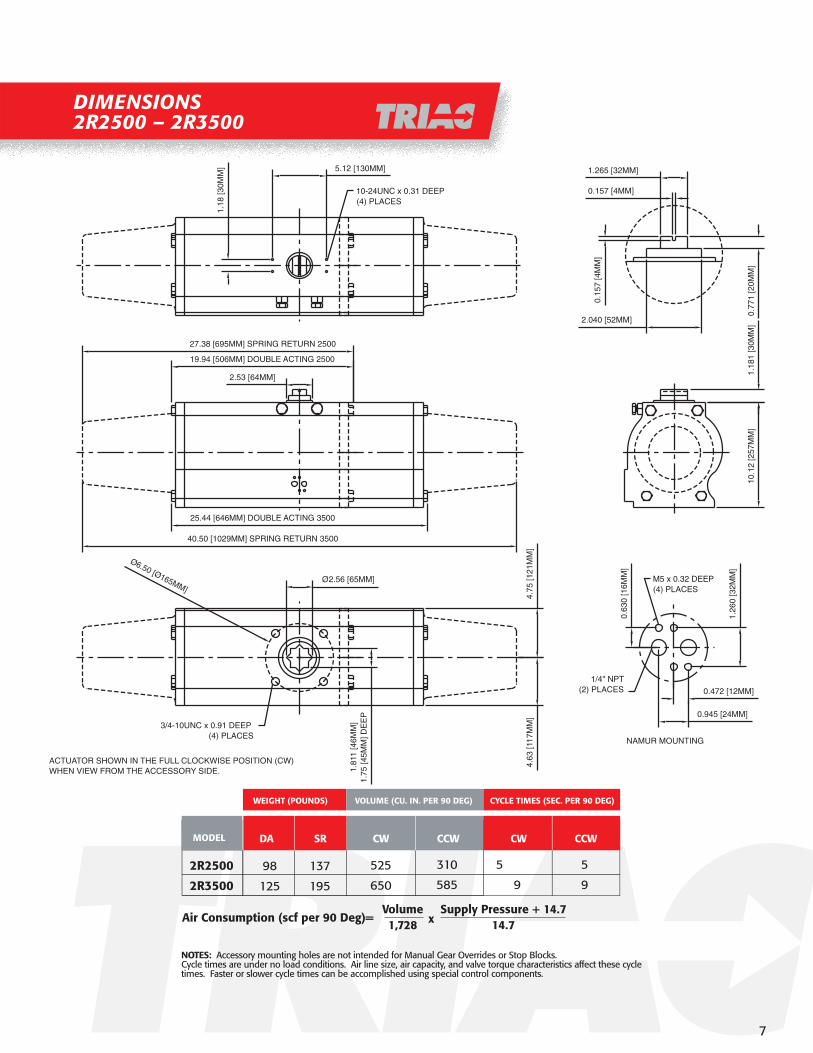
DIMENSIONS2R2500 – 2R3500
NOTES: Accessory mounting holes are not intended for Manual Gear Overrides or Stop Blocks. Cycle times are under no load conditions. Air line size, air capacity, and valve torque characteristics affect these cycle times. Faster or slower cycle times can be accomplished using special control components.
98
125
137
195
525
650
310
585
5
9
5
9
2R2500
2R3500
Air Consumption (scf per 90 Deg)= xVolume1,728
Supply Pressure + 14.714.7
MODEL
WEIGHT (POUNDS) VOLUME (CU. IN. PER 90 DEG)
DA SR CW CCW CW CCW
CYCLE TIMES (SEC. PER 90 DEG)
(4) PLACES3/4-10UNC x 0.91 DEEP
(4) PLACES10-24UNC x 0.31 DEEP
(2) PLACES1/4" NPT
(4) PLACESM5 x 0.32 DEEP
27.38 [695MM] SPRING RETURN 2500
19.94 [506MM] DOUBLE ACTING 2500
1.265 [32MM]
2.53 [64MM]
25.44 [646MM] DOUBLE ACTING 3500
1.18
1 [3
0MM
]10
.12
[257
MM
]
5.12 [130MM]
1.18
[30M
M]
40.50 [1029MM] SPRING RETURN 3500
1.26
0 [3
2MM
]
0.63
0 [1
6MM
]
0.472 [12MM]
0.945 [24MM]
NAMUR MOUNTING
0.157 [4MM]
0.77
1 [2
0MM
]
2.040 [52MM]
0.15
7 [4
MM
]
ACTUATOR SHOWN IN THE FULL CLOCKWISE POSITION (CW)WHEN VIEW FROM THE ACCESSORY SIDE.
Ø6.50 [Ø165MM]2.56 [65MM]Ø
4.63
[117
MM
]4.
75 [1
21M
M]
1.75
[45M
M] D
EE
P1.
811
[46M
M]

Available for many of the most popular resilient seated butterfly valves
Call for details and availability
Usually requires no additional hardware
Lower profile packages
Wide base accommodates pattern without transition plate
TRIAC actuators feature a wide base to enable direct mounting to many butterfly valves without transition plates. Contact factory for compatibility with your particular butterfly.
PART #TKA-010 PART #TKA-020 PART #TKA-030 PART #TKA-040 PART #TKA-050
REQUIREDFOR 2" & 3" FOR 2" & 3"
REQUIRED REQUIREDFOR 4" FOR 5" & 6"
REQUIREDFOR 8"
REQUIRED
Adapter Dimensions for 2K Series
Dimensions – 2K Series
Refer to valve dimensions for actual sizing
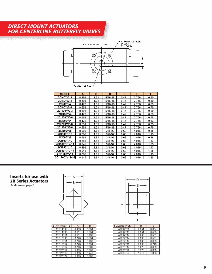
Other inserts are available on request.
0.881
0.628
0.755
0.503
0.250
1.125
1.2261.226
0.250
1.125
0.631
0.441
1.125
0.250
1.2260.568
0.378
1.226
1.125
0.250
0.7500.568
0.500
0.378
Ø
Ø
2K40 2K80 - 2K200 2K300 - 2K1200
0.378 FLATS x 1.31 DEEP
0.568 DIA.
Ø3.250BOLTCIRCLE
3/8-16 UNC THD x 0.56 DEEP(4) HOLES, STRADDLE CL
0.503 FLATS x 1.31 DEEP
0.755 DIA.
3/8-16 UNC THD x 0.56 DEEP(4) HOLES, STRADDLE CL
CIRCLEBOLTØ3.250 0.250 SQ. KEY
Ø1.125 BORE x 2.06 DEEP
5.000
3.250
(4) HOLES, STRADDLE CL3/8-16 UNC THD x 0.56 DEEP
(4) HOLES, STRADDLE CL1/2-13 UNC THD x 0.75 DEEP
Note: 2K850 and 2K1200 have only 5" bolt circle
TR2500-TR3500
DIRECT MOUNTFOR BUTTERFLY VALVES
8
E
DB
A
STAR INSERTS A B
ATD11T09 0.433 0.354ATD14T09 0.551 0.354ATD14T11 0.551 0.433ATD19T09 0.748 0.354ATD19T11 0.748 0.433ATD19T14 0.748 0.551ATD19T17 0.748 0.669ATD27T17 1.063 0.669ATD27T19 1.063 0.748ATD27T22 1.063 0.866
SQUARE INSERT D E
ATE14T09 0.551 0.354ATE14T11 0.551 0.433ATE17T14 0.669 0.551ATE22T14 0.866 0.551ATE22T17 0.866 0.669ATE22T19 0.866 0.748ATE26T17 1.023 0.669ATE35T22 1.378 0.866ATE36T27 1.417 1.063
Inserts for use with 2R Series ActuatorsAs shown on page 6
MODEL A B C D E F
2CI40**/2-3 0.394 1.31 5/16-18 0.47 2.756 0.502CI80**/2-3 0.394 1.31 5/16-18 0.47 2.756 0.502CI80**/4 0.472 1.31 5/16-18 0.47 2.756 0.63
2CI80**/5-6 0.551 1.31 5/16-18 0.47 2.756 0.752CI130**/2-3 0.394 1.31 5/16-18 0.47 2.756 0.502CI130**/4 0.472 1.31 5/16-18 0.47 2.756 0.63
2CI130**/5-6 0.551 1.31 5/16-18 0.47 2.756 0.752CI200**/4 0.472 1.31 5/16-18 0.47 2.756 0.63
2CI200**/5-6 0.551 1.31 5/16-18 0.47 2.756 0.752CI300**/5-6 0.551 1.31 5/16-18 0.47 2.756 0.752CI300**/8 0.669 1.81 3/8-16 0.63 4.016 0.882CI300**/10 0.866 1.81 3/8-16 0.63 4.016 1.132CI500**/8 0.669 1.81 3/8-16 0.63 4.016 0.882CI500**/10 0.866 1.81 3/8-16 0.63 4.016 1.13
2CI500**/12-14 0.945 1.81 3/8-16 0.63 4.016 1.252CI850**/10 0.866 1.81 3/8-16 0.63 4.016 1.13
2CI850**/12-14 0.945 1.81 3/8-16 0.63 4.016 1.252CI1200**/10 0.866 1.81 3/8-16 0.63 4.016 1.13
2CI1200**/12-14 0.945 1.81 3/8-16 0.63 4.016 1.25
DIRECT MOUNT ACTUATORSFOR CENTERLINE BUTTERFLY VALVES
9

APL & EX Series
Direct mount TVC series
Nipple mount available
Weatherproof/explosion proof construction
Intrinsically safe coilavailable
Various voltages - AC or DC
Quick exhaust modification
2 or 3 position control
Exhaust speed controls
Aluminum housing
Weatherproof/explosion proof construction
Dome indicator
Easy-Set cams
Captive bolts
many switch options
AS-I systems
Can be mounted onmanual valves
Solenoid Valves
All Accessory Options Available
TVCS-X411-4NDirect Mount Solenoids
APL-310
Limit Switches
ACCESSORIES
10
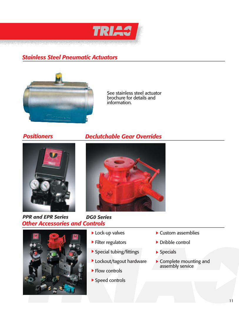
Lock-up valves
Filter regulators
Special tubing/fittings
Lockout/tagout hardware
Flow controls
Speed controls
Custom assemblies
Dribble control
Specials
Complete mounting andassembly service
See stainless steel actuator brochure for details and information.
PPR and EPR Series DG0 Series
Positioners Declutchable Gear Overrides
Stainless Steel Pneumatic Actuators
Other Accessories and Controls
11

SPECIFICATION ANDORDERING INFORMATION
Sample SpecificationActuator shall be TRIAC TR/2R series rack and pinion design. Body to be hard anodized, extruded aluminum for corrosion protection and shall have a base wide enough for stable mounting to valve mounting pads. Internals to feature dual aluminum piston racks and a one-piece electroless nickel plated blow-out proof pinion. Pinion shall also have significant body housing bearings with O ring seals to prevent premature cycle-life failure. Unit to have dual adjustable travel stops and overtravel in both directions. Fasteners and hardware to be stainless steel. Standard bottom mounting dimensions to conform to ISO5211 and accessory mounting to NAMUR-VDI/VDE guildlines.
2 Triac Rack & Pinion Actuator with double travel stopsT Triac Rack & Pinion Actuator with single travel stop (discontinued from 40 ~ 3500)
R ISO / DIN mounting configurationCI Direct mount to Centerline BFVK Direct mount to Keystone / ABZ / Ultraflow BFVN Direct mount to Nibco BFV
Note: Others available, call for details
0000 Actuator size (10, 20, 40, 80, 130, 200, 300, 500, 850, 1200, 1750, 2500, 3500)
DA Double acting configurationDAR Double acting (reverse acting) configurationSR Spring return fail clockwise configurationSO Spring return fail counter-clockwise configuration
Blank Standard Buna seals (-20˚F to 175˚F)V Viton seals (0˚F to 300˚F)LT Low temperature Buna seals (-45˚F to 175˚F)
Blank 5 springs per side (SR & SO only)0 Number of spring per side (1, 2, 3, 4, 6) (SR & SO only)
E Extra long travel stops
Example: 2R80SRE (Model 80 Rack & Pinion Actuator with Travel Stop in both directions, Spring Return fail clockwise, with Extra long travel stops)
TRIAC Model Number Matrix
12

OPERATIONAL DETAILSAND FEATURES
Support
Dual Travel Stop Adjustment
5o 5o
5o
5o
90 o
100 o
80 o
Triac 2R Series features a splined stop collar that provides travel stop adjustments in both the clockwise and counter-clockwise directions. The splined collar ensures minimal hysteresis and repeatable stop positions.
13
Engineering assistance and AUTOCAD drawings available
SP
PR
-SE
RIE
SP
NE
UM
AT
IC P
OS
ITIO
NE
R
THE DESIGN AND DISCLOSURE CONTAINED IN THIS DRAWING WAS ORIGINATED BY, AND IS EXCLUSIVE PROPERTY OF A-T CONTROLS, INC.
REVISION
DATEDATE
APPROVED
TITLE
DATE
DRAWN
CONT ROLS
Division of A-T Controls11363 Deerfield RoadCincinnati, Ohio 45242Phone: (513) 247-5465Fax: (513) 247-5462
ECN# DATE BY
BAG
07/24/02
BM
07/24/02
TRIAC 2R-SERIES ACTUATOR WITH PPR POSITIONER
PNEUMATIC DIAGRAM
OUT 2
OUT 1
P1
P2
POSITIONER3-15 PSI
PPR
SIGNAL
SUPPLY
TRIACPPR SERIESPOSITIONER
TRIAC 2R-SERIESRACK AND PINIONACTUATOR
C
DIRECT ACTINGINCREASE SIGNALRESULTS IN A COUNTERCLOCKWISE ROTATION
OUT 2
1/4" NPTSIGNAL AIRCONNECTION3-15 PSI
1/4" NPTAIR SUPPLYCONNECTION
OUT 1
B
D
E
A
MINIMUM CLEARENCE1.63 INCHES
CLOSED
THE DESIGN AND DISCLOSURE CONTAINED IN THIS DRAWING WAS ORIGINATED BY, AND IS EXCLUSIVE PROPERTY OF A-T CONTROLS, INC.
REVISION
DATEDATE
APPROVED
TITLE
DATE
DRAWN
CONT ROLS
Division of A-T Controls11363 Deerfield RoadCincinnati, Ohio 45242Phone: (513) 247-5465Fax: (513) 247-5462
ECN# DATE BY
BAG
08/09/02
BM
08/09/02
TRIAC 2R 1750DA RACK AND PINION ACTUATORWITH TWIST SET TS-V3-2 LIMIT SWITCH, TRIAC TVC5-X411-4N-A120 SOLENOIDBLOCK AND BLEED, TRIAC DGO-6 WORM GEAR WITH HANDWHEELTRIAC FR-100 FILTER REGULATOR
TRIACTWIST SETTS-V3-2LIMIT SWITCH
TRIAC2R 1750DA
RACK & PINIONACTUATOR
TRIACFR-100FILTER
REGULATOR
TRIACDGO-6WORM GEAR
BLOCK & BLEEDVALVE
TRIAC TVC5-X411-4N-A120
4-WAY SOLENOID
1/4" NPT SUPPLYAIR CONNECTION
1/2" NPT CONDUITCONNECTION
1/2" NPT CONDUITCONNECTION(2 PLACES)
8.27
10.12
23.15
9.38
4.00
NOC NC
WIRING DIAGRAM
TEMPERATURE: -4°F TO 176°F
TS-V3-2MECHANICAL SPDTRATING 250 VOLTS 10 AMPS
14.35
25.57
5.63
8.31
C NCNO
OP
TIO
NA
LS
OLE
NO
ID

EXPLODED VIEW ANDBILL OF MATERIAL
1
2
3
4
5
6
7
8
9
10
11
11
1212
13
13
14
14
15
15 16
16
17
17
18
18
1920
2122
23
23
24
25
No. Description Qty. Material Remarks1 Cylinder Body 1 Aluminum Hard Anodized2 Pinion 1 Steel Electroless Nickel Plated3 Bottom Pinion Bushing 1 Nylon4 Bottom Pinion O-ring 1 Nitrile Buna5 Travel Stop Cam 1 SCM21 Phosphate Coated6 Top Pinion Bushing 1 Nylon7 Top Pinion O-ring 1 Nitrile Buna8 Pinion Teflon Washer 1 RTFE9 Pinion SST Washer 1 304 Stainless Steel10 Snap Ring 1 Steel Electroless Nickel Plated11 Piston 2 Die Cast Aluminum Dichromate Dipped12 Guide Plate 2 Nylon13 Piston O-ring 2 Nitrile Buna14 Piston Guide Band 2 PTFE15 End Cap O-ring 2 Nitrile Buna16 Hole Sealant 2 Nitrile Buna17 End Cap 2 Die Cast Aluminum Epoxy Coated18 End Cap Bolt 2 304 Stainless Steel19 Travel Stop Bolt 2 304 Stainless Steel20 Travel Stop Nut 2 304 Stainless Steel21 Travel Stop Washer 2 304 Stainless Steel22 Travel Stop O-ring 2 Nitrile Buna23 Spring Cartridge 12 Spring Steel Epoxy Coated24 Dust Plug 2 Polyethylene25 Position Indicator 1 Polyethylene
1 2 3
2
3
3
3
1
1
2
2
1
2121
21
21
21
21
2121
Nitrile Buna 2RKB(Actuator Size) -20oF ~ +175oFViton 2RKV(Actuator Size) 0oF ~ +300oFLow Temp Buna 2RKLT(Actuator Size) -45oF ~ +175oF
Example: 2RKB0130 = Nitrile Buna Repair Kit for 2R130
Nitrile Buna 2BOK(Actuator Size) -20oF ~ +175oFViton 2VOK(Actuator Size) 0oF ~ +300oFLow Temp Buna 2LTOK(Actuator Size) -45oF ~ +175oF
Example: 2VOK0080 = Viton Seal Kit for 2R80
Repair Kit
Seal Kit
Recommended spare partsParts included in a repair kitParts included in a seal kit3
21
14
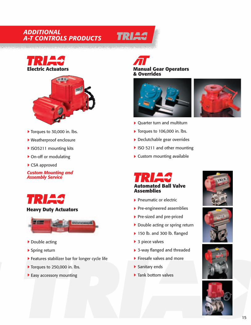
ADDITIONALA-T CONTROLS PRODUCTS
Torques to 30,000 in. lbs.
Weatherproof enclosure
ISO5211 mounting kits
On-off or modulating
CSA approved
Manual Gear Operators& Overrides
Quarter turn and multiturn
Torques to 106,000 in. lbs.
Declutchable gear overrides
ISO 5211 and other mounting
Custom mounting available
Automated Ball ValveAssemblies
Pneumatic or electric
Pre-engineered assemblies
Pre-sized and pre-priced
Double acting or spring return
150 lb. and 300 lb. flanged
3 piece valves
3-way flanged and threaded
Firesafe valves and more
Sanitary ends
Tank bottom valves
Custom Mounting andAssembly Service
Electric Actuators
15
Heavy Duty Actuators
Double acting
Spring return
Features stabilizer bar for longer cycle life
Torques to 250,000 in. lbs.
Easy accessory mounting

11363 Deerfield Rd.Cincinnati, Ohio 45242
(513) 247-5465FAX (513) 247-5462
e-mail: [email protected] site: www.a-tcontrols.com
DIVISION OF
Complete Valve Automation
1106-RP


