UNIVERSITY OF GAZİANTEP FACULTY OF ENGINEERING DEPARTMENT OF MECHANICAL ENGINEERING ME 308 MACHINE ELEMENT II PROJECT SPRING DESIGN PROJECT SUBMITTED TO:NİHAT YILDIRIM SUBMITTED BY: NAME:Mustafa SURNAME:Cigal
Transcript
UNIVERSITY OF GAZİANTEP
FACULTY OF ENGINEERING
DEPARTMENT OF MECHANICAL ENGINEERING
ME 308 MACHINE ELEMENT II PROJECT
SPRING DESIGN PROJECT
SUBMITTED TO:NİHAT YILDIRIM
SUBMITTED BY:
NAME:Mustafa
SURNAME:Cigal
NUMEBER:200961089 DATE:25.03.2013
MY PROJECT DATES……………………………………………………………….…………2
INTRODUCTION…….………………………………………..…………………….………...3 HIATORY OS SPRINGS…………………….………..………………….………..3 SPRINGS……………………………………….……………………………………….3 Design procedure for the helical springs……………………………...4
CALCULATIONS CORNER SPRING CALCULATION…………………………………….…..…5
OUTER SPRING CALCULATION…………….………….15 BUCLING……………………………….................17 FREQUENCY……………………………..…………..17 FATIQUE……………………………………..………..18
ANOTHER DİAMETER ASSUMTION………………………………………….………...20 CONCLUSION …………………………………..………………………………………………..21 REFERANCES……………………………………………………………………………………….22 EXCEL PROGRAM PICTURES……………………………………………………………….23
1
MY PROJECT DATAS
Spring production type = unpeened Mass of bottom die =50 kg Dimension A = 35mm İnitial compression due to bottom die weigth =8mm Spring material =chrome vanadium End condition = plain and ground Reliability =99% Frequency of load = 3Hz Factor of safty =2 Expected life = 5×10⁵
2
INTRODUCTION
In this project, we will design a compression spring according to the given values and the necessary assumptions. There are six spring of 4 columns hydrolic pres machine. These springs are corners and centers springs. Four of springs is in corners and two of springs is in center. First I will design the corner springs. This 4 spring is the same of each other so I will design one of them. Then I will design the center springs. This 2 spring are differs from each other so, I will design two of them. I wrote a Excel program to design all of this spring and I will assume d and D values and ratio of load carried of center springs in the program and I will decide the best design.
Of course, we must check the failure conditions for a proper design. Before starting the design calculations, i want to give some information about springs.
HISTORY OF THE SPRINGS
Like most other fundamental mechanisms, metal springs have existed since the Bronze Age. Even before metals, wood was used as a flexible structural member in archery bows and military catapults. Precision springs first became a necessity during the Renaissance with the advent of accurate timepieces. The fourteenth century saw the development of precise clocks which revolutionized celestial navigation. World exploration and conquest by the European colonial powers continued to provide an impetus to the clockmakers' science and art. Firearms were another area that pushed spring development.
The eighteenth century dawn of the industrial revolution raised the need for large, accurate, and inexpensive springs. Whereas clockmakers' springs were often hand-made, now springs needed to be mass-produced from music wire and the like. Manufacturing methodologies were developed so that today springs are ubiquitous. Computer-controlled wire and sheet metal bending machines now allow custom springs to be tooled within weeks, although the throughput is not as high as that for dedicated machinery.
SPRINGS
When a designer wants rigidity, negligible deflection is an acceptable approximation as long as it does not compromise function. Flexibility is sometimes needed and is often provided by metal bodies with cleverly controlled geometry. These bodies can exhibit flexibility to the degree the designer seeks. Such flexibility can be linear or nonlinear in relating deflection to load. These devices allow controlled application of force or torque; the storing and release of energy can be another purpose. Flexibility allows temporary distortion for access and the immediate restoration of function. Because of machinery‟s value to designers, springs have been intensively studied; moreover, they are mass-
3
produced (and therefore low cost), and ingenious configurations have been found for a variety of desired applications.
Springs are the mechanical elements which transfer a tensile or compressive force with a certain linear deflection or torque with angular deformation.
They also store energy and release it when the load or torque is removed from the system.
They have a characteristic called „‟spring rate‟‟ , „‟spring constant” or „‟scale of spring‟
F= kY
Design procedure for the helical springs
Most of the spring parameters are unknown at the beginning of a design stage. Each design is an iteration procedure of assuming some parameters & values
(material, C, d, or Do, Di etc). Afterwards, you have to check whether other geometric constraints & failure criteria
are satisfied or not. However, reaching a suitable solution may require lots of iteration and calculation steps
To ease the design process, most spring design problems can be put into a tabulation-iteration form similar to (spreadsheets) as seen in following example:
ASSUMEd(mm)
C Ks τ max
MPaSut
MPaSy
MPaSsy
MPaτ max<¿Ssy
9 Failure7 Failure6 satisfactory
4
Y
CALCULATIONS
1.CORNER SPRING CALCULATIONS :
First I will design the corner springs. This 4 spring is the same of each other so, I will design one of them. Proroject say that; half of the total load is caried by the springs at the corners and remaining load is caried by the nested spring(at the center).
Fmintotal ¿FminT=m× g=50× 9,81→ FminT=490.5 N
Fmin ( for corner 4 springs )=Fmin−corn=FminT
2=490,5
2=245,25→ Fmin−corn=245.25 N
Fmin ( for onespring )=Fmin=Fmin−corn
4=245.25
4=61.3125 N → Fmin=61.3125 N
k=∆ F∆ y
→ k=Fmin−0δi−0
=61,31258
=7,664061 Nmm
Fmax=k× (δ i+δ duringoperation )=7.664061 × (8+35 )=329.5547 N
Fmax=329.5547 N
Assume - wire diameter d=5.7 mm
(D¿¿hole−Do)≥ 0.1× d ¿ D0 ≤ 119.43
(D¿¿ i−Drod )≥ 0.1× d ¿ Dİ ≤ 50.57
D=Dİ+d=D0-d
Assume Coil diameter D=65 mm
Sut=Adm = 2000
5,70 ,167=1495.543 MPa
Sy=0.75× Sut=0.75× 1495.543=1121.657 MPa
Ssy=0.577× S y=0.577 × 1121.657=647.1962 M Pa
C= Dd
= 655.7
=11.4035
K s=1+ 0.5C
=1.043846
5
must be 4 ≤ C ≤ 12∧our C=¿11.4035 so satisfy
τ max=K s×8 × Fmax × D
π ×d3 =1.043846× 8× 329.5547 ×65π ×5.73
τ max=307.463 MPa
n=Ssy
τmax=647.1962
307.463=2.104956
İn my Project factor of safety(n) is 2 and I calculate the n (with d=5.7 and D=65) 2.104956 is greater and very close the 2. SO calculated sping is satisfy the static design.
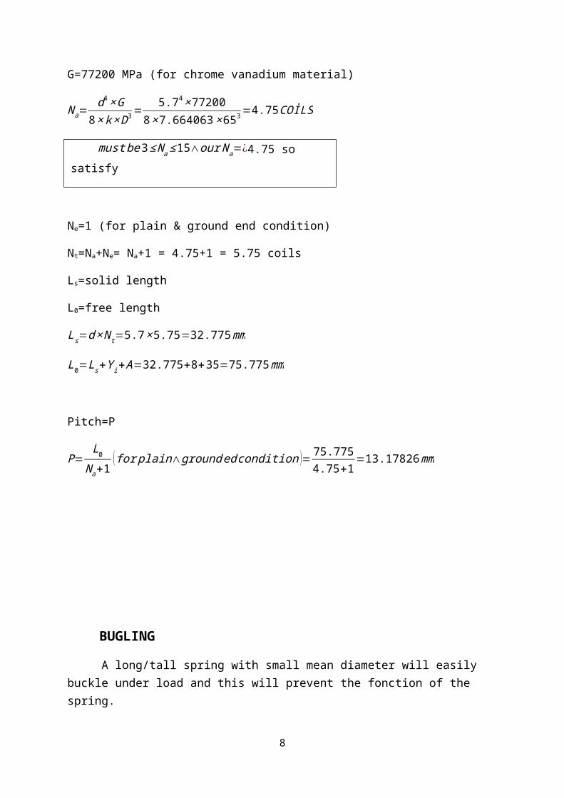
G=77200 MPa (for chrome vanadium material)
Na=d4× G
8 × k × D3 =5.74 ×77200
8× 7.664063× 653 =4.75 COİLS
must be3≤ Na ≤15∧our Na=¿4.75 so satisfy
Ne=1 (for plain & ground end condition)
Nt=Na+Ne= Na+1 = 4.75+1 = 5.75 coils
Ls=solid length
L0=free length
Ls=d × N t=5.7 ×5.75=32.775 mm
L0=Ls+Y i+ A=32.775+8+35=75.775 mm
Pitch=P
P=L0
Na+1( for plain∧ground ed condition )= 75.775
4.75+1=13.17826 mm
6
BUGLING
A long/tall spring with small mean diameter will easily buckle under load and this will prevent the fonction of the spring.
To prevent buckling of springs the geometrical ratios between (look figure 4)
Free length and mean diameter and Lf
D (Lf=L0)(figure 4)
Deflection under maximum load and free length YLf
(figure 4)
Have to be kept in certain limits.
Lf
D=75.775
65=1.165769
YLf
= 35+875.775
=0.567469
İt is in certain limit, so ,there is no buckling failure.
7
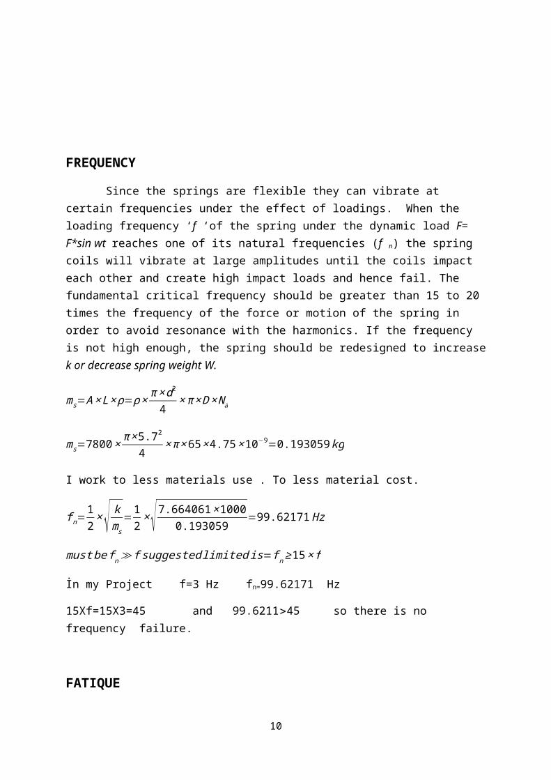
FREQUENCY
Since the springs are flexible they can vibrate at certain frequencies under the effect of loadings. When the loading frequency ‘f ‘of the spring under the dynamic load F= F*sin wt reaches one of its natural frequencies (f n) the spring coils will vibrate at large amplitudes until the coils impact each other and create high impact loads and hence fail. The fundamental critical frequency should be greater than 15 to 20 times the frequency of the force or motion of the spring in order to avoid resonance with the harmonics. If the frequency is not high enough, the spring should be redesigned to increase k or decrease spring weight W.
ms=A × L× ρ=ρ × π ×d2
4× π × D × N a
ms=7800× π ×5.72
4× π × 65× 4.75 ×10−9=0.193059 kg
I work to less materials use . To less material cost.
f n=12
×√ kms
=12
×√ 7.664061 ×10000.193059
=99.62171 Hz
must be f n ≫ f suggested limited is=f n ≥ 15× f
İn my Project f=3 Hz fn=99.62171 Hz
15Xf=15X3=45 and 99.6211>45 so there is no frequency failure.
FATIQUE
In most applications springs are subjected to fatigue loading since they have to deflect between some points.The life of the springs may change from a few thousands cycle to millions of cycle.
In designing springs to resist fatigue failure, we start with calculating alternating and mean components of the force.
Fa=Fmax−Fmin
2=329.5547−61.3125
2=134.12111 N
Fm=Fmax+ Fmin
2=329.5547+61.3125
2=195.4336 N
τ a=K s ×
8 × Fa × Dπ ×d3 =1.04384 × 8 ×134.12111× 65
π× 5.73 =125.1303 MPa
8
τ m=K s×
8× Fm × Dπ ×d3 =1.04384 × 8 ×195.4336 × 65
π × 5.73 =182.3327 MPa
Sse=k c × kd × ke × Sse'
-kc=reliability factor for 99% reliability=0.814
-kd=temperature effect=1
k e=1
K c
K c=KK s
K= 4× C−14×C−4
+ 0.615C
=4× 11.40351−14×11.40351−4
+ 0.61511.40351
=1.126022
K s=1+ 0.5C
=1+ 0.511.40351
=1.043846
K c=KK s
=1.0787241.043846
=1.078724
k e=1
K c= 1
1.078724=0.92702
Sse' =310 MPa for unpeened
Sse=0.814 × 1× 0.92702× 310=233.9245 MPa
Sse=233.9245 MPa
Ssf =10c × Nb
N=5x10⁵ cycle in my project
Ssu=0.6 × Sut=0.6 ×1495.543=897.3258 MPa
c= log( (0.8 × Ssu)2
Sse)=log (0.8× 897.3258 )2
233.9245=3.343
b=−13
× log( 0.8× Ssu
Sse)=−1
3× log 0.8× 897.3258
233.9245=−0.16232
Ssf =10c × Nb=103.343×500000−0.16232=261.782 MPa
n=Ssf
τa= 261.782
125.1303=2.092
9
İn my Project factor of safety(n) is 2 and I calculate the n (with d=5.7 and D=65) 2.092 is greater and very close the 2. SO calculated sping is satisfy the fatige effect. SO there is no fatique failure for 5x10⁵ cycle.
In my design to 1 spring at the corner Fmax=329.5547. The total Fmaxt=4xFmax Fmaxt= 4x329.5547=1318.219 N. And Proroject say that; half of the total load is caried by the springs at the corners and remaining load is caried by the nested spring(at the center). Acording to this; maximum capacity of the hydrolic pres machine =2xFmaxt=2x1318.219
maximum capaciyi of the hydrolic pres =2636.438 N(acording to corner springs).
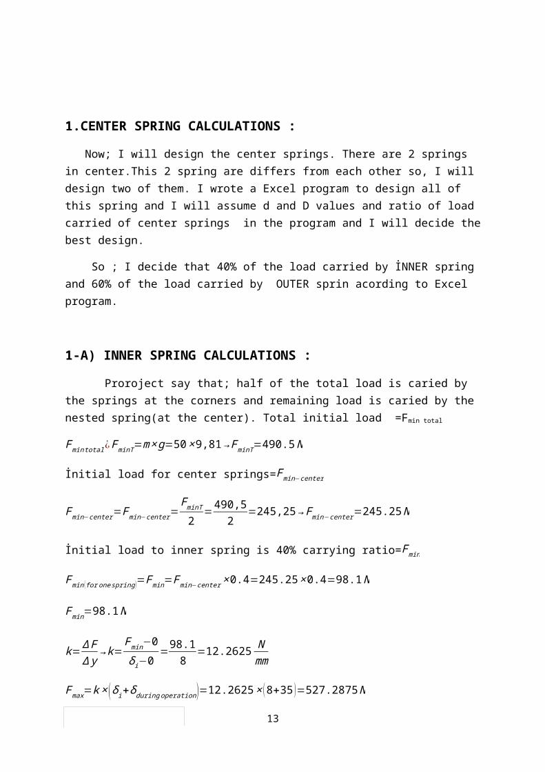
1.CENTER SPRING CALCULATIONS :
Now; I will design the center springs. There are 2 springs in center.This 2 spring are differs from each other so, I will design two of them. I wrote a Excel program to design all of this spring and I will assume d and D values and ratio of load carried of center springs in the program and I will decide the best design.
So ; I decide that 40% of the load carried by İNNER spring and 60% of the load carried by OUTER sprin acording to Excel program.
1-A) INNER SPRING CALCULATIONS :
Proroject say that; half of the total load is caried by the springs at the corners and remaining load is caried by the nested spring(at the center). Total initial load =Fmin total
Fmintotal ¿FminT=m× g=50× 9,81→ FminT=490.5 N
İnitial load for center springs=Fmin−center
Fmin−center=Fmin−center=FminT
2=490,5
2=245,25→ Fmin−center=245.25 N
İnitial load to inner spring is 40% carrying ratio=Fmin
Fmin ( for onespring )=Fmin=Fmin−center × 0.4=245.25× 0.4=98.1 N
Fmin=98.1 N
10
k=∆ F∆ y
→ k=Fmin−0δi−0
=98.18
=12.2625 Nmm
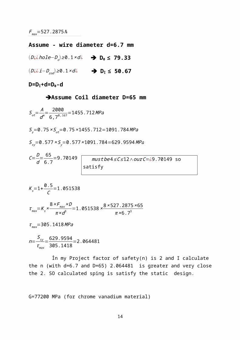
Fmax=k× (δ i+δ duringoperation )=12.2625 × (8+35 )=527.2875 N
Fmax=527.2875 N
Assume - wire diameter d=6.7 mm
(D¿¿hole−Do)≥ 0.1× d ¿ D0 ≤ 79.33
(D¿¿ i−Drod )≥ 0.1× d ¿ Dİ ≤ 50.67
D=Dİ+d=D0-d
Assume Coil diameter D=65 mm
Sut=Adm= 2000
6,70 ,167=1455.712 MPa
Sy=0.75× Sut=0.75× 1455.712=1091.784 MPa
Ssy=0.577× S y=0.577 × 1091.784=629.9594 MPa
C= Dd
= 656.7
=9.70149
K s=1+ 0.5C
=1.051538
τ max=K s×8 × Fmax × D
π ×d3 =1.051538× 8 × 527.2875× 65π × 6.73
τ max=305.1418 MPa
n=Ssy
τmax=629.9594
305.1418=2.064481
İn my Project factor of safety(n) is 2 and I calculate the n (with d=6.7 and D=65) 2.064481 is greater and very close the 2. SO calculated sping is satisfy the static design.
G=77200 MPa (for chrome vanadium material)
Na=d4× G
8 × k × D3 =6.74 ×77200
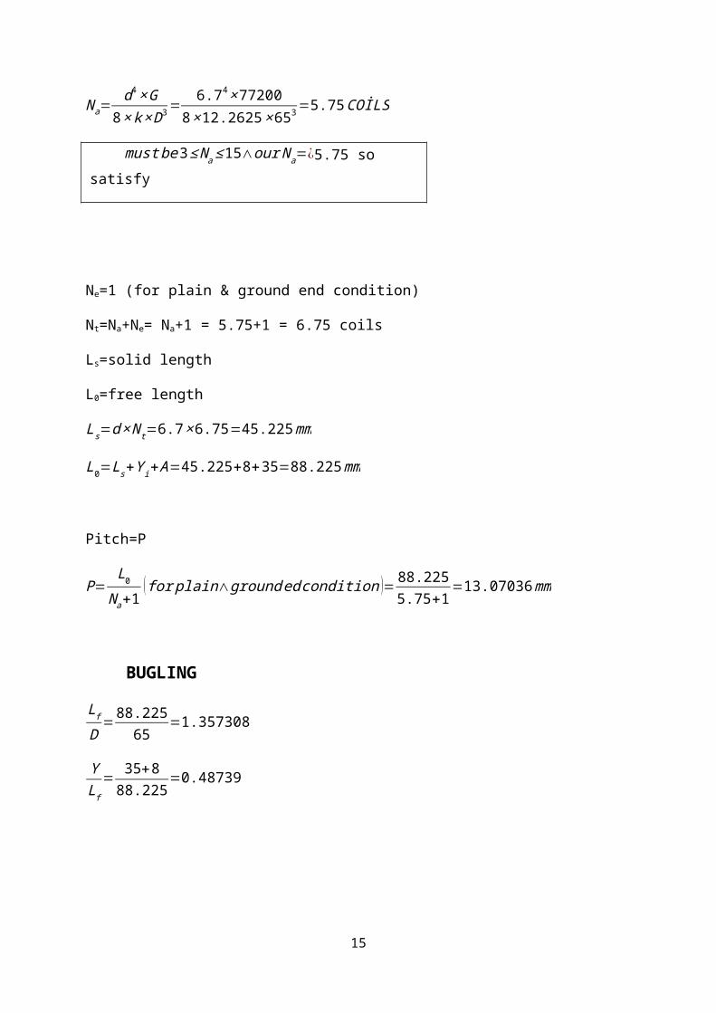
8× 12.2625× 653 =5.75 COİLS
11
must be 4 ≤ C ≤ 12∧our C=¿9.70149 so satisfy
must be3≤ Na ≤15∧our Na=¿5.75 so satisfy
Ne=1 (for plain & ground end condition)
Nt=Na+Ne= Na+1 = 5.75+1 = 6.75 coils
Ls=solid length
L0=free length
Ls=d × N t=6.7 ×6.75=45.225 mm
L0=Ls+Y i+ A=45.225+8+35=88.225 mm
Pitch=P
P=L0
Na+1( for plain∧ground ed condition )= 88.225
5.75+1=13.07036 mm
BUGLING
Lf
D=88.225
65=1.357308
YLf
= 35+888.225
=0.48739
12
İt is in certain limit, so ,there is no buckling failure.
FREQUENCY
ms=A × L× ρ=ρ × π ×d2
4× π × D × N a
ms=7800× π ×6.72
4× π× 65 ×5.75 ×10−9=0.322898 kg
I work to less materials use . To less material cost.
f n=12
×√ kms
=12
×√ 12.2625 ×10000.322898
=97.43768 Hz
must be f n ≫ f suggested limited is=f n ≥ 15× f
İn my Project f=3 Hz fn=97.43768 Hz
15Xf=15X3=45 and 97.43768>45 so there is no frequency failure.
FATIQUE
Fa=Fmax+ Fmin
2=527.2875−98.1
2=214.59375 N
Fm=Fmax+ Fmin
2=527.2875+98.1
2=312.6938 N
τ a=K s ×
8 × Fa × Dπ ×d3 =1.04384 × 8 ×214.59375 ×65
π × 6.73 =124.1856 MPa
13
τ m=K s×
8× Fm × Dπ ×d3 =1.04384 × 8 ×312.638 ×65
π × 6.73 =180.9562 MPa
Sse=k c × kd × ke × Sse'
-kc=reliability factor for 99% reliability=0.814
-kd=temperature effect=1
k e=1
K c
K c=KK s
K= 4× C−14×C−4
+ 0.615C
=4× 9.701493−14×9.701493−4
+ 0.6159.701493
=1.149584
K s=1+ 0.5C
=1+ 0.59.701493
=1.051538
K c=KK s
=1.1495841.051538
=1.09324
k e=1
K c= 1
1.09324=0.914712
Sse' =310 MPa for unpeened
Sse=0.814 × 1× 0.91472× 310=230.8184 MPa
Sse=230.8184 MPa
Ssf =10c × Nb
N=5x10c cycle in my project
Ssu=0.6 × Sut=0.6 ×1455.712=873.4273 MPa
c= log( (0.8 × Ssu)2
Sse)=log (0.8× 873.4273 )2
230.8184=3.325
b=−13
× log( 0.8× Ssu
Sse)=−1
3× log 0.8 × 873.4273
230.8184=−0.16035
Ssf =10c × Nb=103.325×500000−0.16035=257.9528 MPa
n=Ssf
τa=257.9528
124.1856=2.077155
14
İn my Project factor of safety(n) is 2 and I calculate the n (with d=6.7 and D=65) 2.077155 is greater and very close the 2. SO calculated sping is satisfy the fatige effect. SO there is no fatique failure for 5x10⁵ cycle.
In my design to inner spring at the center have Fmax=527.2875 N .The total Fmaxt=Fmax /0.4 Fmaxt= 527.2875/0.4=1318.21875 N. And Proroject say that; half of the total load is caried by the springs at the corners and remaining load is caried by the nested spring(at the center). Acording to this; maximum capacity of the hydrolic pres machine =2xFmaxt=2x1318.21875n
maximum capaciyi of the hydrolic pres =2636.4375 N(acording to iner spring at center).
2-B) OUTER SPRING CALCULATIONS :
Proroject say that; half of the total load is caried by the springs at the corners and remaining load is caried by the nested spring(at the center). Total initial load =Fmin total
Fmintotal ¿FminT=m× g=50× 9,81→ FminT=490.5 N
İnitial load for center springs=Fmin−center
Fmin−center=Fmin−center=FminT
2=490,5
2=245,25→ Fmin−center=245.25 N
İnitial load to OUTER spring to 60% carrying ratio=Fmin
Fmin ( for onespring )=Fmin=Fmin−center × 0.6=245.25 × 0.6=147.15 N
Fmin=147.15 N
k=∆ F∆ y
→ k=Fmin−0δi−0
=147.158
=18.39375 Nmm
Fmax=k× (δ i+δ duringoperation )=18.39375 × ( 8+35 )=790.9313 N
Fmax=790.9313 N
Assume - wire diameter d=8.8 mm
(D¿¿hole−Do)≥ 0.1× d ¿ D0 ≤ 139.12
15
(D¿¿ i−Drod )≥ 0.1× d ¿ Dİ ≤ 80.88
D=Dİ+d=D0-d
Assume Coil diameter D=90 mm
Sut=Adm= 2000
8,80 ,167=1390.918 MPa
Sy=0.75× Sut=0.75× 1390.918=1043.188 MPa
Ssy=0.577× S y=0.577 × 1043.188=601.9196 MPa
C= Dd
= 908.8
=10.2273
K s=1+ 0.5C
=1.048889
τ max=K s×8 × Fmax × D
π ×d3 =1.048889× 8 × 790.9313× 90π ×8.83
τ max=278.9991 MPa
n=S sy
τmax= 601.9196
278.9991=2.157425
İn my Project factor of safety(n) is 2 and I calculated the n (with d=8.8 and D=90) 2.157425 is greater and very close the 2. SO calculated sping is satisfy the static design.
G=77200 MPa (for chrome vanadium material)
Na=d4× G
8 × k × D3 =8.84 ×77200
8× 18.39375× 903 =4.25COİLS
must be3≤ Na ≤15∧our Na=¿4.25 so satisfy
Ne=1 (for plain & ground end condition)
Nt=Na+Ne= Na+1 = 4.25+1 = 5.25 coils
Ls=solid length
16
must be 4 ≤ C ≤ 12∧our C=¿10.2273 so satisfy
L0=free length
Ls=d × N t=8.8 ×5.25=46.2 mm
L0=Ls+Y i+ A=46.2+8+35=89.2mm
Acording to Project L0 for iner spring must be smaller then L0 for outer spring. İn previous calculation I calculate L0 for iner spring =88.225 and I calculate L0 for outer spring = 89.2 becaus of 89.2>88.225 this calculation satisfy.
Pitch=P
P=L0
Na+1( for plain∧ground ed conditi on )= 89.2
4.25+1=16.99048 mm
BUGLING
Lf
D=89.2
90=0.9911
YLf
=35+889.2
=0.482063
İt is in certain limit, so ,there is no buckling failure.
FREQUENCY
17
ms=A × L× ρ=ρ × π ×d2
4× π × D × N a
ms=7800× π ×8.82
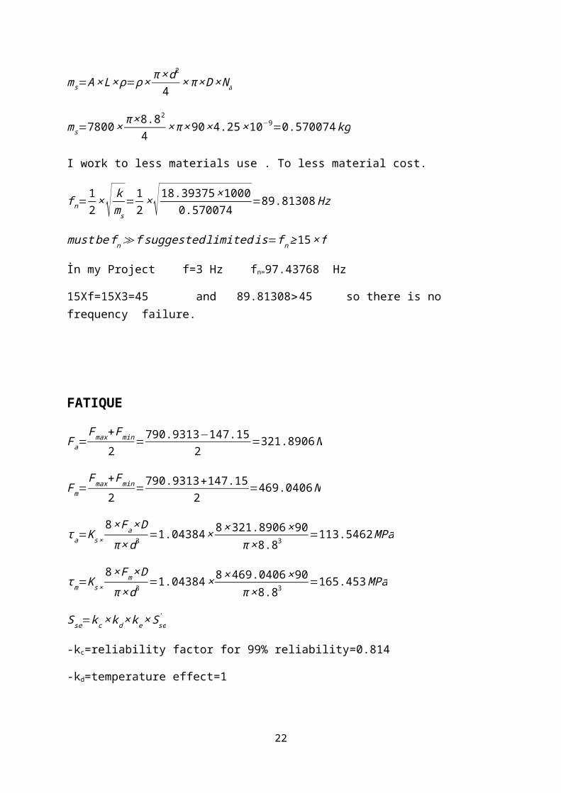
4× π× 90 × 4.25× 10−9=0.570074 kg
I work to less materials use . To less material cost.
f n=12
×√ kms
=12
×√ 18.39375 ×10000.570074
=89.81308 Hz
must be f n ≫ f suggested limited is=f n ≥ 15× f
İn my Project f=3 Hz fn=97.43768 Hz
15Xf=15X3=45 and 89.81308>45 so there is no frequency failure.
FATIQUE
Fa=Fmax+ Fmin
2=790.9313−147.15
2=321.8906 N
Fm=Fmax+ Fmin
2=790.9313+147.15
2=469.0406 N
τ a=K s ×
8 × Fa × Dπ ×d3 =1.04384 × 8 ×321.8906 × 90
π × 8.83 =113.5462 MPa
τ m=K s×
8× Fm × Dπ ×d3 =1.04384 × 8 × 469.0406 ×90
π ×8.83 =165.453 MPa
Sse=k c × kd × ke × Sse'
-kc=reliability factor for 99% reliability=0.814
-kd=temperature effect=1
k e=1
K c
K c=KK s
K= 4× C−14×C−4
+ 0.615C
=4 × 10.22727−14 ×10.22727−4
+ 0.61510.22727
=1.141414
18
K s=1+ 0.5C
=1+ 0.510.22727
=1.048889
K c=KK s
=1.1414141.048889
=1.088213
k e=1
K c= 1
1.048889=0.918938
Sse' =310 MPa for unpeened
Sse=0.814 × 1× 0.918938× 310=231.8848 MPa
Sse=231.8848 MPa
Ssf =10c × Nb
N=5x10c cycle in my project
Ssu=0.6 × Sut=0.6 ×1390.918=834.5505 MPa
c= log( (0.8 × Ssu)2
Sse)=log (0.8× 834.5505 )2
231.8848=3.284
b=−13
× log( 0.8× Ssu
Sse)=−1
3× log 0.8 × 834.5505
231.8848=−0.15309
Ssf =10c × Nb=103.284×500000−0.15309=257.844 MPa
n=Ssf
τa= 257.844
113.5462=2.27083
İn my Project factor of safety(n) is 2 and I calculate the n (with d=8.8 and D=90) 2.27083 is greater and very close the 2. SO calculated sping is satisfy the fatige effect. SO there is no fatique failure for 5x10⁵ cycle.
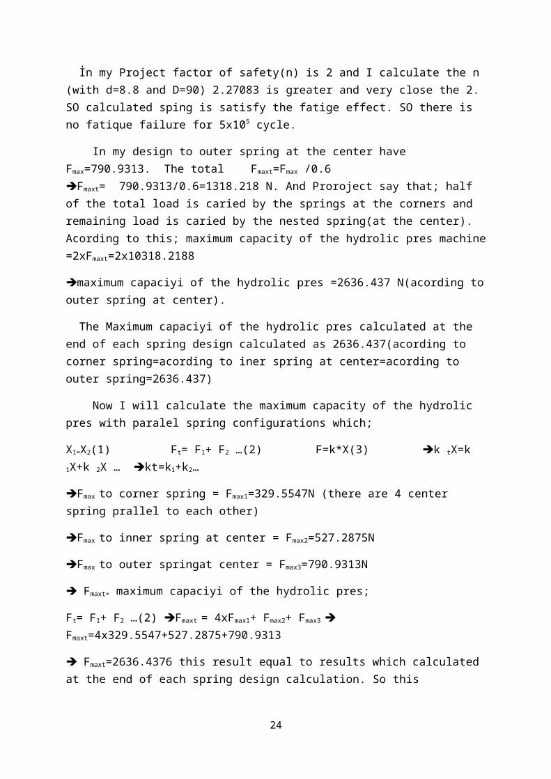
In my design to outer spring at the center have Fmax=790.9313. The total Fmaxt=Fmax /0.6 Fmaxt= 790.9313/0.6=1318.218 N. And Proroject say that; half of the total load is caried by the springs at the corners and remaining load is caried by the nested spring(at the center). Acording to this; maximum capacity of the hydrolic pres machine =2xFmaxt=2x10318.2188
maximum capaciyi of the hydrolic pres =2636.437 N(acording to outer spring at center).
The Maximum capaciyi of the hydrolic pres calculated at the end of each spring design calculated as 2636.437(acording to corner spring=acording to iner spring at center=acording to outer spring=2636.437)
19
Now I will calculate the maximum capacity of the hydrolic pres with paralel spring configurations which;
Fmaxt=2636.4376 this result equal to results which calculated at the end of each spring design calculation. So this calculation is correct and maximum capaciyi of the hydrolic pres(Fmaxt) is =2636.4376.
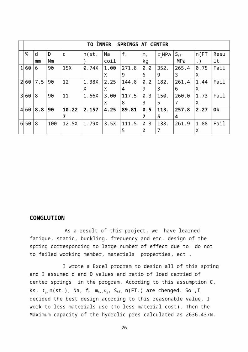
Another diameter is assumed. We used to calculate computer program (excel).These values in table are taken this program
As a result of this project, we have learned fatique, static, buckling, frequency and etc. design of the spring corresponding to large number of effect due to do not to failed working member, materials properties, ect .
I wrote a Excel program to design all of this spring and I assumed d and D values and ratio of load carried of center springs in the program. Acording to this assumption C, Ks, τ a
,n(st.), Na, fn, ms,,τ a, Ssf, n(FT.) are chenged. So ,I decided the best design acording to this reasonable value. I work to less materials use (To less material cost). Then the Maximum capacity of the hydrolic pres calculated as 2636.437N.
REFERENCES
1-Shigley,E,J ”Mechanical engineering design”
2-ME 308 lecture note by NİHAT YILDIRIM
3-INTERNET
21
EXCEL PROGRAM PICTURE WHICH I WRITE FOR THIS PROJECT