* Energy Research Group-UTT, University of Trinidad and Tobago, Trinidad and Tobago, (E-mail: [email protected]) ** Dept. of Electrical Engineering, Faculty of Engineering, Suez Canal University, 41522, Ismailia, Egypt, (E-mail: [email protected]) IJPE, 4:1 (2012): 41-57 Research Science Press, New Delhi, India A FACTS Based Static Switched Filter Compensator for Voltage Control and Power Quality Improvement in Wind Smart Grid ADEL M. SHARAF * AND ABDELAZEEM A. ABDELSALAM ** Abstract: The renewable energy sources, which have been expected to be a promising alternative energy source, can bring new challenges when it is connected to the power grid. This paper presents a novel FACTS based Static Switched Filter Compensation (SSFC) scheme. This FACTS SSFC scheme is an effective power quality mitigation, voltage stabilization, power losses reduction and power factor enhancement tool for wind schemes interfaced with Smart Grid-Distribution Networks. The FACTS SSFC-device is controlled by two regulators based on a tri-loop dynamic error driven inter-coupled input to a weighted modified PID controller. The FACTS filter compensation scheme has been fully validated for effective harmonic mitigation, voltage stabilization, losses reduction and power factor correction using the Matlab Simulink software environment. The proposed FACTS Static Switched Filter Compensator Scheme can be extended to integrate other distributed/dispersed distributed generation schemes for power quality and power factor enhancement and compensation requirements such as voltage stabilization and efficient utilization. Keywords: FACTS, Static Switched Filter Compensator, Dynamic Controllers, Wind Energy Utilization, Voltage Stabilization. 1. INTRODUCTION To have sustainable growth and social progress, it is necessary to meet the energy need by utilizing the renewable energy resources like wind, biomass, hydro, co-generation, etc. In sustainable energy system, energy conservation and the use of renewable source are the key paradigm. The need to integrate the renewable energy like wind energy into power
Transcript
* Energy Research Group-UTT, University of Trinidad and Tobago, Trinidad and Tobago,(E-mail: [email protected])
** Dept. of Electrical Engineering, Faculty of Engineering, Suez Canal University, 41522, Ismailia,Egypt, (E-mail: [email protected])
IJPE, 4:1 (2012): 41-57Research Science Press, New Delhi, India
A FACTS Based Static Switched FilterCompensator for Voltage Control and Power
Quality Improvement in Wind Smart Grid
ADEL M. SHARAF* AND ABDELAZEEM A. ABDELSALAM**
Abstract: The renewable energy sources, which have been expected to be apromising alternative energy source, can bring new challenges when it isconnected to the power grid. This paper presents a novel FACTS based StaticSwitched Filter Compensation (SSFC) scheme. This FACTS SSFC scheme is aneffective power quality mitigation, voltage stabilization, power losses reductionand power factor enhancement tool for wind schemes interfaced with SmartGrid-Distribution Networks. The FACTS SSFC-device is controlled by tworegulators based on a tri-loop dynamic error driven inter-coupled input to aweighted modified PID controller. The FACTS filter compensation scheme hasbeen fully validated for effective harmonic mitigation, voltage stabilization, lossesreduction and power factor correction using the Matlab Simulink softwareenvironment. The proposed FACTS Static Switched Filter Compensator Schemecan be extended to integrate other distributed/dispersed distributed generationschemes for power quality and power factor enhancement and compensationrequirements such as voltage stabilization and efficient utilization.
Keywords: FACTS, Static Switched Filter Compensator, Dynamic Controllers,Wind Energy Utilization, Voltage Stabilization.
1. INTRODUCTION
To have sustainable growth and social progress, it is necessary to meetthe energy need by utilizing the renewable energy resources like wind,biomass, hydro, co-generation, etc. In sustainable energy system, energyconservation and the use of renewable source are the key paradigm.The need to integrate the renewable energy like wind energy into power
system is to make it possible to minimize the environmental impact onconventional plant [1]. The integration of wind energy into existingpower system presents technical challenges and that requiresconsideration of voltage regulation, stability, power quality problems.The power quality is an essential customer-focused measure and isgreatly affected by the operation of a distribution and transmissionnetwork. The issue of power quality is of great importance to the windturbine [2]. There has been an extensive growth and quick developmentin the exploitation of wind energy in recent years.
Wind energy conversion systems (WECS) is a form of viable andeffective renewable green energy sources that convert wind kineticenergy to mechanical energy that can be used to drive different ACand DC type generators [3]. Typically, the WECS comprises a windturbine, gear box, generator, interconnection converter, and therequired control systems. The WECS can be connected as eitherstand-alone for supplying power to local isolated loads in remote areas,or connected to the electric grid system. Owing to very large windfarms emerging, the dispersed renewable wind energy is required tobe fully connected to the electrical distribution networks [4]. However,increased penetration of the dispersed wind energy creates an uncertainand challenging scenario for the electric power grid system. In remoteand isolated sites, the power obtained from wind energy integratedwith the electric grid can reach the same order of magnitude asgrid-power transferred, which means that the mutual impact betweenwind-energy schemes and the electric grid networks must be takeninto account. Dynamic electric load variations and wind velocityexcursions cause excessive changes in the prime mover kinetic energyand the corresponding electrical power injected into the AC grid utilitysystem [5, 6]. In short, it is necessary to provide effective and economicaltechnical solutions for both power quality and security aspects relatedto the electric grid with distributed and dispersed wind energy schemes.Fortunately, the new emerging FACTS technologies can perform newstabilization and fast power control functions by quickly switchingsolid-state devices [7].
In general, FACTS devices are used in transmission control whereascustom power devices are used for distribution control. Since theintroduction of FACTS and custom power devices such as UnifiedPower Flow Controller (UPFC), synchronous static compensator(STATCOM), dynamic voltage restorer (DVR), solid-state transferswitch and solid-state fault current limiter have been developed forimproving power quality and reliability of a system [8-14]. Advanced
A FACTS BASED STATIC SWITCHED FILTER COMPENSATOR FOR VOLTAGE… / 43
control and improved semiconductor switching of these devices havereached a new era for power quality mitigation.
The FACTS and custom power devices have been developed formitigating specific power quality problems. For example, UPFC workswell for power flow control, DVR which acts as a series compensatoris used for voltage sag compensation and STATCOM which is a shuntcompensator is used for reactive power and voltage sag compensation.The STATCOM, DVR, UPS and active power conditioner are only usefulfor compensating a particular type of power quality problems andtherefore, it has become necessary to develop a new kind of UnifiedSeries-Shunt Compensator (USSC) which can mitigate a wider rangeof power quality problems. Many FACTS devices based on Switchedfilter compensator which used the principle of USSC had beenpublished [15- 20].
This paper presents a FACTS based static switched filtercompensator (SSFC) scheme for effective voltage stabilization, powerquality enhancement, losses reduction and power factor improvementin distribution grid networks with the dispersed wind energy interface.The FACTS SSFC is based on controlled complementary switchingprocess between two capacitor banks to be connected with the classicaltuned. The switching process is achieved by novel dynamic controlstrategies and the pulse width modulation-complementary switching(PWM). Two error dynamic regulation schemes are utilized with atri-loop dynamic error inter-coupled control strategy and a weightedmodified PID controller. The SSFC- FACTS device scheme has beenfully validated for effective power quality mitigation, voltagestabilization, losses reduction and power factor correction using MatlabSimulink environment.
2. THE STATIC SWITCHED FILTER COMPENSATOR
The FACTS SSFC scheme, shown in Figure 1, is a combination of twoseries capacitor banks (CS1 and CS2) and two shunt capacitor banks(Cm1 and Cm2) in parallel with the capacitor element (CF) of a tuned armfilter (RF, LF and CF). An intermittent switching process between thetwo shunt capacitor banks is achieved by novel dynamic controlstrategies.
3. CONTROLLER DESIGN
In order to reduce the harmonics, improve the power factor andstabilize the buses voltage using the FACTS static switched filtercompensator, an integrated dynamic control based on two regulators
44 / IJPE, 4(1) 2012
Figure 1: The Novel FACTS Static Switched Filter Compensator Scheme
A and B are proposed. The global error is the sum of the two inter-coupled regulators output. The global error signal is an input to theweighted modified PID controller to regulate the modulating controlsignal to the PWM switching block as shown in Figure 2. The weighted
Figure 2: The Weighted Modified PID Control of the FACTS SSFC Scheme
A FACTS BASED STATIC SWITCHED FILTER COMPENSATOR FOR VOLTAGE… / 45
modified PID (WMPID) includes error sequential activationsupplementary loops to ensure fast dynamic response andaffective damping of large excursion, in addition to conventional PIDstructure.
3.1. Regulator A
In this regulator, shown in Figure 3, the voltage and current waveformare used in a tri loop error to provide a stable voltage at all AC busesand to improve the power factor. This is achieved by modulating theadmittance of the SSFC.
3.2. Regulator B
This regulator, shown in Figure 4, is used to suppress any voltage andcurrent harmonic ripples and consequently mitigate the harmonics.
Figure 3: The Tri-loop Error Driven Regulator A 6
Figure 4: The Tri-loop Error Driven Regulator B
46 / IJPE, 4(1) 2012
Figure 5: Single Line Diagram of the Sample Study Distribution System with theNovel FACTS Switched Filter Compensation Scheme
4. DIGITAL SIMULATION OF THE STUDIED AC SYSTEM
4.1. The AC System Configuration
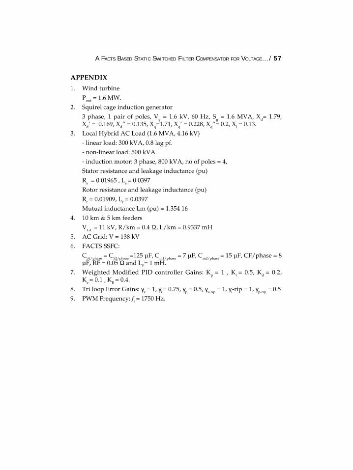
The studied AC system is 11 KV distribution network with a renewablewind energy source and is connected to 138 kV AC grid through11/138kV step up transformer. A hybrid load comprises a linear load,a converter type nonlinear load and an induction motor load isconnected to the distribution network through 11/4.16kV stepdown transformer. Figure 3 depicts a single line diagram of thestudied AC system. The detail parameters of the system are given inAppendix.
4.2. Simulation Results of Digital Simulation
The Matlab/Simulink digital simulation results for the proposed hybridFACTS-Switched Filter Compensation Scheme HFCS is validated fortwo study cases are as follow:
A FACTS BASED STATIC SWITCHED FILTER COMPENSATOR FOR VOLTAGE… / 47
42.1. Case 1: Normal Loading Operation
The two complementry switching pulses (PA, PB) to the hybrid FACTSfilter is shown in Figure 6.
The dynamic response of voltage, current, active power, reactivepower, apparent power and power factor at the source (Bs) and load(BL) buses under normal operation with and without using hybridFACTS filter are shown in Figures 7-12.
Figure 6: PWM Switching Pulses; PA and PB
In the previous figures, with using the FACTS filter compensator,the rms value of the voltage waveform at the source and load busesare increased. In addition, the current flow through the source bus isdecreased and the load current is increased.
At the infinite bus (Bi), the rms value of voltage waveform doesnot change and the rms value of waveform current increases with usingthe FACTS filter compensator.
48 / IJPE, 4(1) 2012
Figure 7: The rms Voltage and Current at the Generator Bus, Bs
Figure 8: The Apparent Power and Power Factor at the Generator Bus, Bs
Figure 9: The rms Voltage and Current at the Load Bus, BL 9
A FACTS BASED STATIC SWITCHED FILTER COMPENSATOR FOR VOLTAGE… / 49
Figure 10: The Apparent Power and Power Factor at the Load Bus, BL
Figure 11: The rms Voltage and Current at the Infinite bus, Bi
Figure 12: The Apparent Power and Power Factor at the Infinite bus, Bi 10
50 / IJPE, 4(1) 2012
The active and reactive power losses are calculated and are shownin Figure 13. As shown in this figure, with using the FACTS staticswitching filter compensator, the active and reactive power losses inthe two feeders (10 & 5 km) are increased.
Figure 13: The Active and Reactive Power Losses Without and with FACTS SSFC
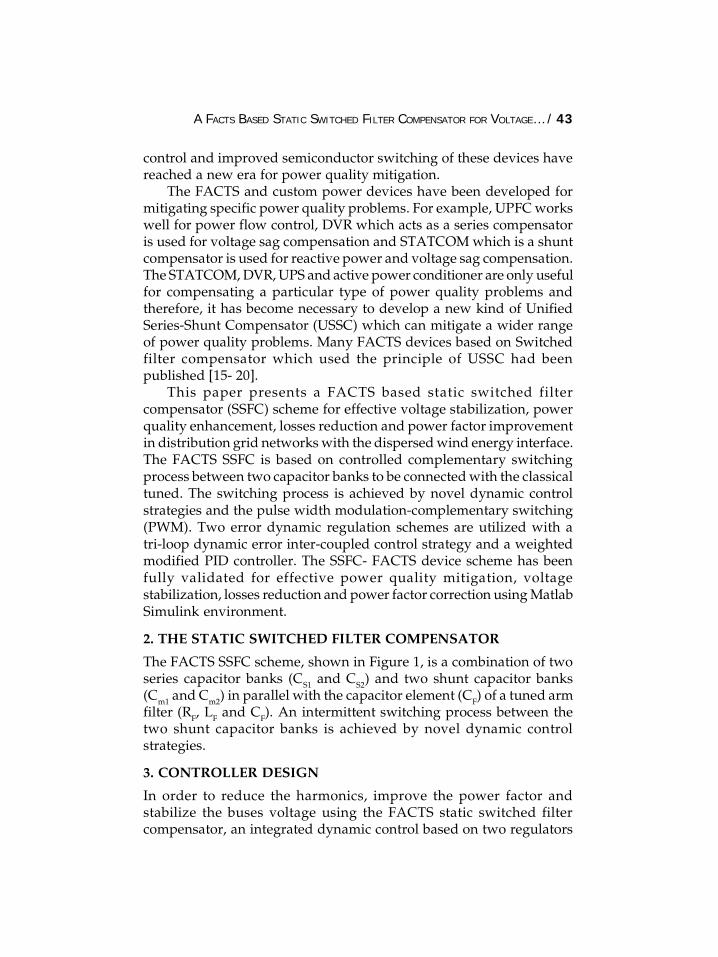
The frequency spectra of the voltage and current waveforms areshown in Figures 14-19. The voltage and current harmonic analysis interm of the total harmonic distortion (THD) is summarized in Table 1.It is obvious that the voltage harmonics are significantly reduced to alevel within the limit set by the IEEE Std. 519-1992 regarding the THDof bus voltage at low voltage system (less than 69 kV) [21]. Also theTHD of current waveform at each bus is decreased.
Figure 14: The Frequency Spectrum of Voltage Waveform at the Generator Bus,Bs, Without and With the FACTS Filter Compensator
A FACTS BASED STATIC SWITCHED FILTER COMPENSATOR FOR VOLTAGE… / 51
Figure 15: The Frequency Spectrum of Current Waveform at the Generator Bus,Bs, Without and With the FACTS Filter Compensator
Figure 16: The Frequency Spectrum of Voltage Waveform at the Load bus, BL,Without and With the FACTS Filter Compensator
Figure 17: The Frequency Spectrum of Current Waveform at the Load Bus, BL,Without and With the FACTS Filter Compensator
52 / IJPE, 4(1) 2012
Table 1THD of the voltage and current waveforms
% THD of Voltage % THD of CurrentWaveform Waveform
Without With SSFC Without With SSFC
Generator bus Bg 8.9 0.44 5.1 1.6Load bus BL 22.7 0.33 18.5 1.3Infinite bus Bi 0.05 0.045 11.3 1.7
4.2.2. Case 2: Sudden Change of The Wind Speed and The Load Excursion
In this case study, the digital simulation is carried out with and withoutthe controlled SFC located at load bus for 1.0 second in order to showits performance under the following disturbance sequence:
Figure 18: The Frequency Spectrum of Voltage Waveform at the Infinite bus, Bi,Without and With the FACTS Filter Compensator
Figure 19: The Frequency Spectrum of Current Waveform at the Infinite Bus, Bi,Without and With the FACTS Filter Compensator
A FACTS BASED STATIC SWITCHED FILTER COMPENSATOR FOR VOLTAGE… / 53
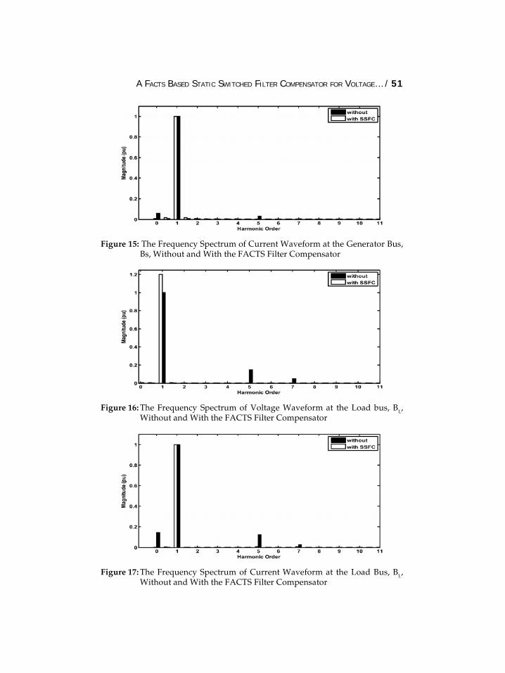
• At t = 0.1 second, the linear load is removed for a duration of0.1 seconds;
• At t = 0.3 second, the nonlinear load is removed for a durationof 0.1 seconds;
• At t = 0.5 second, wind speed suddenly decreased to 9 m/s fora duration of 0.1 seconds;
• At t = 0.7 second, wind speed suddenly increased to 21 m/sfor a duration of 0.1 seconds;
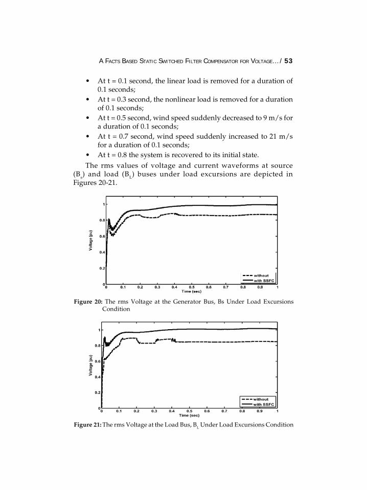
• At t = 0.8 the system is recovered to its initial state.The rms values of voltage and current waveforms at source
(Bs) and load (BL) buses under load excursions are depicted inFigures 20-21.
Figure 20: The rms Voltage at the Generator Bus, Bs Under Load ExcursionsCondition
Figure 21: The rms Voltage at the Load Bus, BL Under Load Excursions Condition
54 / IJPE, 4(1) 2012
Figure 20 shows, without using the FACTS SSFC scheme, thedisconnection of the linear and nonlinear loads have an effect onthe value of voltage at the generator and load buses. It causes avoltage swell. While with using the controlled FACTS SSFC scheme,there is no effect on the voltage waveforms. This means that thecontrolled FACTS SSFC scheme mitigates the swell event of PQdisturbances.
Also, the use of FACTS SSFC scheme mitigates the sag caused inthe current waveforms at infinite bus as shown in Figure 21.
From all the previous figures, it can be observed- The controlled FACTS SSFC scheme mitigates the harmonic
distortion that caused by the nonlinear load where all valuesof THD for voltage and current at all AC buses are decreasedto values within allowable limits of IEEE standard.
- The power losses are decreased using the FACTS SSFC scheme
- The short duration PQ disturbances such as sag and swell aremitigated.
- The gradually change in wind speed does not appear on thevoltage and active power waveform while the sudden changehave a small effect on it.
5. CONCLUSION
This paper presents a FACTS based static switched filtercompensator (SSFC) scheme for effective voltage stabilization,power quality enhancement, losses reduction and power factorimprovement in distribution grid networks with the dispersed windenergy interface. The FACTS SSFC is based on controlledcomplementary switching process between two capacitor banks tobe connected with the classical tuned. The switching process isachieved by novel dynamic control strategies and the pulse widthmodulation-complementary switching (PWM). Two error dynamicregulation schemes are utilized with a tri-loop dynamic error inter-coupled control strategy and a weighted modified PID controller.The SSFC-FACTS device scheme has been fully validated foreffective power quality mitigation, voltage stabilization, lossesreduction and power factor correction using Matlab Simulinkenvironment. FACTS SSFC topology variations and other flexibledynamic control techniques can be utilized in hybrid wind-PV-fuelcell AC-DC renewable energy utilization systems.
A FACTS BASED STATIC SWITCHED FILTER COMPENSATOR FOR VOLTAGE… / 55
References
[1] K. S. Hook, Y. Liu, and S. Atcitty, “Mitigation of the Wind GenerationIntegration Related Power Quality Issues by Energy Storage”, EPQU J, Vol.XII, No. 2, 2006.
[2] R. Billinton and Y. Gao, “Multistate wind Energy Conversion System Modelsfor Adequacy Assessment of Generating Systems Incorporating WindEnergy”, IEEE Trans. on Energy Conversion, Vol. 23, No. 1, pp. 163-169, 2008.
[3] Thomas Ackermann, Wind Power in Power Systems, 2005, John Wiley & SonsLtd.
[4] Jamal A. Baroudi, Venkata Dinavahi, Andrew M. Knight,” A Review of PowerConverter Topologies for Wind Generators”, Renewable Energy, Vol. 32, pp.2369-2385, 2007.
[5] J. M. Carrasco, L. G. Franquelo, J. T. Bialasiewicz, E. Galván, R. Guisado, Ma.Á. Prats, J. I. León, and N. M. Alfonso,” Power-Electronic Systems for theGrid Integration of Renewable Energy Sources: A Survey”, IEEE Transactionson Industrial Electronics, Vol. 53, No. 4, pp. 1002-1016, August 2006.
[6] E. H. Camm, M. R. Behnke, O. Bolado, M. Bollen, M. Bradt, C. Brooks, W.Dilling, M. Edds, W. J. Hejdak, D. Houseman, S. Klein, F. Li, J. Li, P. Maibach,T. Nicolai, J. Patiño, S. V. Pasupulati, N. Samaan, S. Saylors, T. Siebert, T.Smith, M. Starke, R. Walling, “Characteristics of Wind Turbine Generatorsfor Wind Power Plants”, IEEE General Meeting, Calgary, 2009.
[7] Narain G. Hingorani and Laszlo Gyugyi, Understanding FACTS: Conceptsand Technology of Flexible AC Transmission System, Institute of Electricaland Electronics Engineers, Inc. 2000. 17.
[8] A. M. Sharaf, and K. Abo-Al-Ez, “A FACTS Based Dynamic CapacitorScheme for Voltage Compensation and Power Quality Enhancement”.Proceedings of the IEEEISIE 2006 Conference, Montreal, Quebec Canada, July2006.
[9] N. Dizdarevic and M. Majstrovic, “FACTS-based Reactive PowerCompensation of Wind Energy Conversion System”, IEEE Bologna Power TechConference, Vol. 2, pp. 2-8, 2003.
[10] A. Elnady, Magdy M. A. Salama, “ Unified Approach for Mitigating VoltageSag and Voltage Flicker Using The DSTATCOM”, IEEE Transactions on PowerDelivery, Vol. 20, No. 2, pp. 992-1000, April 2005.
[11] E. Babaei, M. F. Kangarlu, M. Sabahi, “Mitigation of Voltage DisturbancesUsing Dynamic Voltage Restorer Based on Direct Converters”, IEEETransactions on Power Delivery, Vol. 25, No. 4, pp. 2676-2683, October 2010.
[12] W. C. Lee, D. M. Lee, T. K. Lee,” New Control Scheme for a Unified Power-Quality Compensator-Q With Minimum Active Power Injection”, IEEETransactions on Power Delivery, Vol. 25, No. 2, pp. 1068-1076, April 2010.
[13] A.M. Sharaf, Weihua Wang, Ismail H. Altas, “ Novel STATCOM Controllerfor Reactive Power Compensation in Distribution Networks with DispersedRenewable Wind Energy”, Canadian Conference on Electrical and ComputerEngineering, 2007, CCECE ’07, pp. 3648-3654.
56 / IJPE, 4(1) 2012
[14] M. Aredes, K. Heumann, and E. H. Watanabe, “An Universal Active PowerLine Conditioner,” IEEE Trans. Power Delivery, Vol. 13, No. 2, pp. 545–557,Apr. 1998.
[15] A. M. Sharaf, K. M. Abo-Al-Ez, “A Novel FACTS Based (DDSC) Compensatorfor Power-Quality Enhancement of L.V. Distribution Feeder with a DispersedWind Generator”, International Journal of Emerging Electric Power Systems, Vol.7, Issue 3, Article 6, Aug. 2007.
[16] A. M. Sharaf, W. Wang, and I.H. Altas, “A Novel Modulated Power FilterCompensator for Distribution Networks with Distributed Wind Energy.”International Journal of Emerging Electric Power Systems, Vol. 8, Issue 3, Article6, Aug. 2007.
[17] A. M. Sharaf, A. A. Abdelsalam, “A Novel FACTS Based Dynamic VoltageCompensation Scheme for Smart Electric Grid Stabilization and EfficientUtilization”, IEEE Canadian Conference on Electrical and Computer Engineering,2011, CCECE, 11, pp. 42-47, 18.
[18] A. M. Sharaf, A. A. Abdelsalam, “A Novel Switched Filter CompensationScheme for Power Quality Enhancement and Loss Reduction” InternationalSymposium on Innovations in Intelligent Systems and Applications, INISTA2011, Turkey, pp. 398-403.
[19] A. M. Sharaf, A. A. Abdelsalam, “Power Quality Enhancement in Wind-gridInterface Based on Switched Filter Compensator” International Symposium onInnovations in Intelligent Systems and Applications, INISTA 2011, Turkey, pp.404- 409.
[20] A. M. Sharaf, A. A. Abdelsalam, A. A. Eldesouky, A.A. Sallam, “A NovelFACTS Based Modulated Power Filter Compensation Scheme for SmartElectric Grid Stabilization and Efficient Utilization”, Accepted for Publicationon International Journal of Distributed Energy Resources.
[21] IEEE Std 519-1992, “IEEE Recommended Practices and Requirements forHarmonic Control in Electrical Power Systems”, 1992.
A FACTS BASED STATIC SWITCHED FILTER COMPENSATOR FOR VOLTAGE… / 57