+ All Categories
Home > Documents > A. Fischer, S. Forget, S. Chénais, M.-C. Castex, Lab. de Physique des Lasers, Univ. Paris Nord,...

A. Fischer, S. Forget, S. Chénais, M.-C. Castex, Lab. de Physique des Lasers, Univ. Paris Nord,...

Date post: 14-Dec-2015
Category:
Upload: dale-hodge
View: 213 times
Download: 0 times
Share this document with a friend
Popular Tags:
21
C 2 H 5 C 2 H 5 N N CH 3 CH 3 CH 3 CH 3 CH 3 N C 2 H 5 C 2 H 5 N N CH 3 CH 3 CH 3 CH 3 CH 3 N C 2 H 5 C 2 H 5 N N CH 3 CH 3 CH 3 CH 3 CH 3 N C 2 H 5 C 2 H 5 N N CH 3 CH 3 CH 3 CH 3 CH 3 N CH 3 CH 3 CH 3 CH 3 CH 3 N A. Fischer, S. Forget, S. Chénais , M.-C. Castex, Lab. de Physique des Lasers, Univ. Paris Nord, France Highly efficient multilayer organic Highly efficient multilayer organic pure-blue-light emitting diodes with pure-blue-light emitting diodes with substituted carbazole compounds in the substituted carbazole compounds in the emitting layer. emitting layer. D. Adès, A. Siove, Lab. Biomateriaux et Polymères de Spécialité, Univ. Paris Nord, France C. Denis, P. Maisse and B. Geffroy Lab. Cellules et Composants, CEA Saclay, France
Transcript

C2H5

C2H5

N

N

CH3 CH3

CH3 CH3

CH3

N

C2H5

C2H5

N

N

CH3 CH3

CH3 CH3

CH3

N

C2H5

C2H5

N

N

CH3 CH3

CH3 CH3

CH3

N C2H5

C2H5

N

N

CH3 CH3

CH3 CH3

CH3

N CH3 CH3

CH3 CH3

CH3

N

A. Fischer, S. Forget, S. Chénais, M.-C. Castex,Lab. de Physique des Lasers, Univ. Paris Nord, France

Highly efficient multilayer organic pure-Highly efficient multilayer organic pure-blue-light emitting diodes with blue-light emitting diodes with

substituted carbazole compounds in the substituted carbazole compounds in the emitting layer.emitting layer.

Highly efficient multilayer organic pure-Highly efficient multilayer organic pure-blue-light emitting diodes with blue-light emitting diodes with

substituted carbazole compounds in the substituted carbazole compounds in the emitting layer.emitting layer.

D. Adès, A. Siove, Lab. Biomateriaux et Polymères de Spécialité, Univ. Paris Nord, France

C. Denis, P. Maisse and B. GeffroyLab. Cellules et Composants, CEA Saclay, France

2CLEO ’06 – Long Beach (USA)

Outline

Introduction : why BLUE oleds ? Two new carbazolic compounds : PMC (Pentamethylcarbazole) and DEC (Dimer of N-ethylcarbazole)

Devices using neat films of PMC and DEC in single layer and multilayer structures Devices using doped films of PMC:DPVBi and DEC:DPVBi Conclusion

3CLEO ’06 – Long Beach (USA)

Introduction

Organic Light Emitting Diodes :

Ultrathin light sources, lightweightHigh brightness and viewing angle > 160°Low drive voltage (3-10 V) and low power consumptionExtremely rich diversity of materials : All visible colors available (≠ inorganic LEDs), including saturated colorsPotentially flexible Long lifetimes (> 20 000 h reported)Low cost potential for mass production

Applications : flat-panel RGB DISPLAYS, solid-state lighting,...

4CLEO ’06 – Long Beach (USA)

needs efficient blue emitters

Why BLUE ?

Why Blue OLEDs with high efficiencies are needed ?

different approaches for multi-color emission :

RGB emitters

+ : power efficient, mature

- : different aging and optimization

needs efficient blue emitters

(efficient R,G already exist)

White emitters + Filters

+ : homogeneous aging

- : not efficient (filters)

needs efficient blue emitters

to achieve bright white

Color changing media

+ : homogeneous aging

- : not efficient (photoconversion)

5CLEO ’06 – Long Beach (USA)

OLEDs materials

Requirements for an efficient blue material :

Chemical stability and Electrochemical stability

High Tg

High quantum yield of photoluminescence in the solid state

Chromaticity coordinates approaching

the spectrum locus (saturated color)

Active research for new blue-emitting organic materials(both fluorescent and phosphorescent)

CIE 1931

6CLEO ’06 – Long Beach (USA)

OLEDs materials

Carbazolic derivatives CH3 CH3

CH3 CH3

CH3

N CH3 CH3

CH3 CH3

CH3

N

PMC

C2H5

C2H5

N

N

DEC

Carbazole unit :

penta-methyl carbazole Dimer of N-Ethyl carbazole

• Chemically and thermally stable (up to 430 °C)

• Tg = 75°C

•Polaronic transport levels measured by cyclic voltammetry (eV) :

- Blue emitters: Carbazole-substituted Distyrylarylenes (DSA)

- Hole Transport materials : PVK

- Host material for triplet emitters: CBP

Vacuum level

Lowest Unoccupied Molecular Orbital

Highest Occupied Molecular Orbital

PMC DEC

5.9

2.82.5

5.6

Already used as…

new

7CLEO ’06 – Long Beach (USA)

OLEDs structures

1st DEC-based diode : single layer

Drawbacks:• Low ext. quantum efficiency ext. = 7.10-2

%• High operating voltage (20 V), crystallization during operation (short-circuit)

DEC

ITO

Al

h

VD. Romero, A. Siove et al., Adv. Mater. 9, 1158

(1997)

This work : Use of DEC (and PMC) in a multilayer OLED structure with both neat films and doped films configurations: efficient deep-blue organic emitter

Bad performance due to recombination and quenching of excitons at Al/DEC interface, poor charge injection

8CLEO ’06 – Long Beach (USA)

Device a : OLED with NEAT film of DEC

Anode

ITO

100-150nm

Cathode

LUMO

HOMO

CuPc

10nm

ET

L

NPB

50 nm

Alq3

10nm

LiF / Al

1.2 / 100nm

HIL

HT

L

HB

L

BCP

10nm

5.7

3.0

2.9

2.4

6.1

4.7

5.3

3.6

2.4

5.4 5.

6DEC

50 nm

N

N

N

N

N

N

NN

Cu

CuPc

N N

NPB C2H5

C2H5

N

N

holes

electrons2.4

N

O

AlO

N

O

N

CH3

N

CH3

N

2.5

9CLEO ’06 – Long Beach (USA)

Device a : OLED with neat film of DEC

Anode

Cathode

LUMO

HOMO

ET

LHIL

HT

L

HB

L

5.7

3.0

2.9

2.4

6.1

4.7

5.3

3.6

2.4

5.4 5.

6

C2H5

C2H5

N

N

holes

electrons2.4

2.5

Main recombination zone

ηext = 1.5 % (optical design not optimized)

ITO

100-150nm

CuPc

10nm

NPB

50 nm

Alq3

10nm

LiF / Al

1.2 / 100nm

BCP

10nm

DEC

50 nm

10CLEO ’06 – Long Beach (USA)

Anode

Cathode

LUMO

HOMO

ET

LHIL

HT

L

HB

L

5.7

3.0

2.9

2.4

6.1

4.7

5.3

3.6

2.4

5.4

N

O

AlO

N

O

N

CH3

N

CH3

N

N N

NPB

5.9

2.8

CH3 CH3

CH3 CH3

CH3

Nholes

electrons

Device a : OLED with neat film of PMC

PMC OLED

ηext = 0.6 % → attributed to bad electron transport properties of PMC / electron barrier of BCP

ITO

100-150nm

CuPc

10nm

NPB

50 nm

Alq3

10nm

LiF / Al

1.2 / 100nm

BCP

10nm

PMC

50 nm

11CLEO ’06 – Long Beach (USA)

Device a : OLED with neat film of PMC

Anode

Cathode

LUMO

HOMO

ET

LHIL

HT

L

HB

L

5.7

3.0

2.9

2.4

6.1

4.7

5.3

3.6

2.4

5.4 5.

9

2.8

CH3 CH3

CH3 CH3

CH3

Nholes

electrons

PMC OLED

ηext = 0.6 % → attributed to bad electron transport properties of PMC / electron barrier of BCP

Main recombination zone

ITO

100-150nm

CuPc

10nm

NPB

50 nm

Alq3

10nm

LiF / Al

1.2 / 100nm

BCP

10nm

PMC

50 nm

12CLEO ’06 – Long Beach (USA)

Device a (neat films) : Experimental results

Electroluminescence spectra

a

Chromaticity coordinates

PMC

DEC

Aggregates, excimers ?

PMC : CIE x = 0.153 ; y = 0.100

DEC : CIE x = 0.192 ; y = 0.209Ext. Quantum efficiency : ηext = 0.6 % (PMC)

ηext = 1.5 % (DEC)Brightness L = 236 cd/m2 @ 60 mA/cm2 (PMC)

Luminous efficiency ηpower = 0.2 lm/W (PMC)

→ Bright saturated blueWith PMC, but modest efficiency

13CLEO ’06 – Long Beach (USA)

Investigating emitting mixtures (« doping »)

The role of emitting mixtures (or « doping » but not in the electrical sense !)

« energy transfer » doping = diluting a low-gap guest material inside a wide-gap host : Förster (and Dexter) energy transfers possible

→ Very efficient mechanism but not useful for blue emitters

guestguesthosthost

other types of doping : the dopant « impurities » can enhance exciton recombination by trapping charge carriers (and diffusing excitons)

guestguesthosthost

Ex : Barrier for electrons + trap for holes = improved recombination rate

14CLEO ’06 – Long Beach (USA)

Device b : OLEDs with DPVBi doped with PMC (DEC)

CuPc 10nm

NPB 50nm

DPVBi (PMC or DEC) 50nm

Alq3 10nm

LiF 1.2nm/Al 100nm

(b)

ITO glass

C2H5

C2H5

N

N

DEC

CH3 CH3

CH3 CH3

CH3

N

PMC

+ or

5% wt.

2% wt.DPVBi4,4’-bis(2,2’-diphenylvinyl)-1,1’-biphenyl

Vacuum level

Lowest Unoccupied Molecular Orbital

Highest Occupied Molecular Orbital

PMC DEC

5.9

2.82.5

5.6

DPVBI

5.9

2.8

Doping by coevaporation from 2 resistively heated cells

15CLEO ’06 – Long Beach (USA)

OLEDs with DPVBi doped with DEC

Anode

ITO

100-150nm

Cathode

LUMO

HOMO

CuPc

10nm

ET

L

NPB

50 nm

Alq3

10nm

LiF / Al

1.2 / 100nm

HIL

HT

L

5.7

3.0

2.9

4.7

5.3

3.6

2.4

5.4

DEC:DPVBi

50 nm

holes

electrons2.5

5.6

5.9

2.8

2% DEC

DPVBi

16CLEO ’06 – Long Beach (USA)

OLEDs with DPVBi doped with DEC

Anode

Cathode

LUMO

HOMO ET

L

HIL

HT

L

5.7

3.0

2.9

4.7

5.3

3.6

2.4

5.4

holes

electrons2.5

5.65.9

2.8

2% DEC

DPVBi

Recombination zone

ηext = 3.3 %

ITO

100-150nm

CuPc

10nm

NPB

50 nm

Alq3

10nm

LiF / Al

1.2 / 100nm

DEC:DPVBi

50 nm

17CLEO ’06 – Long Beach (USA)

Anode

Cathode

LUMO

HOMO ET

L

HIL

HT

L

5.7

3.0

2.9

4.7

5.3

3.6

2.4

5.4

holes

electrons

5.9

2.8

5% PMC

DPVBi

OLEDs with DPVBi doped with PMC

Recombination zone

ηext = 2.8 %

ITO

100-150nm

CuPc

10nm

NPB

50 nm

Alq3

10nm

LiF / Al

1.2 / 100nm

PMC:DPVBi

50 nm

18CLEO ’06 – Long Beach (USA)

Anode

Cathode

LUMO

HOMO ET

L

HIL

HT

L

5.7

3.0

2.9

4.7

5.3

3.6

2.4

5.4

holes

electrons

5.9

2.8

DPVBi

Recombination zone

ηext = 2.7 %

Comparison point : OLEDs with DPVBi ALONE

ITO

100-150nm

CuPc

10nm

NPB

50 nm

Alq3

10nm

LiF / Al

1.2 / 100nm

PMC:DPVBi

50 nm

19CLEO ’06 – Long Beach (USA)

Device b (doping) : SUMMARY

PMC:DPVBiDEC:DPVBi

DPVBi

Device (a)PMC

Device (a)DEC

Device (b)DPVBi PMC- doped (5%)

Device (b)DPVBi DEC- doped (2%)

Device (b)DPVBi

nondoped

ext (%) 0.6 1.5 2.8 3.3 2.7power (lm/W) 0.2 … 1.2 1.3 1.2

L (cd/m2) @ 60 mA/cm2

236 … 2279 2825 …

C.I.E. x 0.153 0.192 0.160 0.158 0.149

C.I.E. y 0.100 0.209 0.176 0.169 0.112

► All spectra similar to DPVBi and NPB : which material is emitting light ?

►no shoulder in DEC spectra : suppression of aggregates by dilution

20CLEO ’06 – Long Beach (USA)

Summary

We demonstrated state-of-the-art external quantum efficiency of 3.3% with a deep-blue OLED (CIE x = 0.15 ; y = 0.17) using a DEC:DPVBi emitting mixture

Close to the max 5% = 25% (singlet/triplet ratio) x 20% (extraction

efficiency)

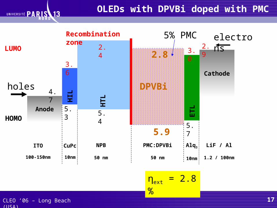
Efficiency of the doping approach : DEC:DPVBi better than DPVBi alone (or DPVBI:PMC) : attributed to enhanced trapping of charged carriers

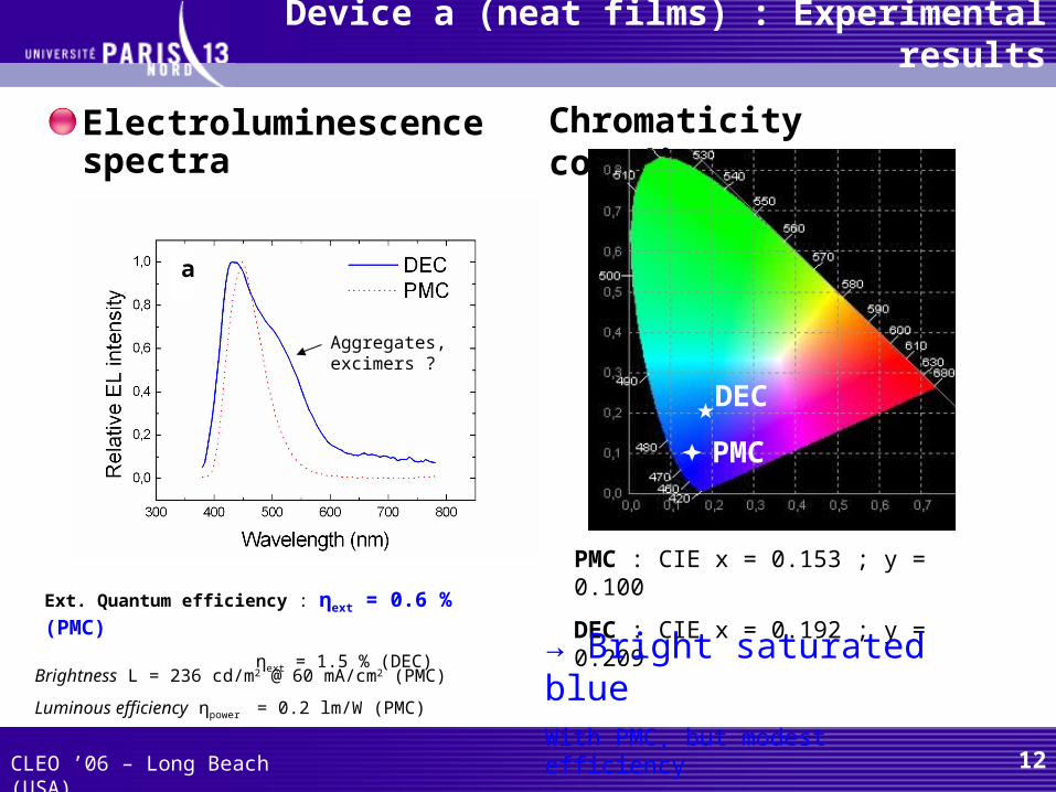
PMC exhibits the most saturated color (x = 0.15 ; y= 0.10) : better efficiency would be achievable with a different design while keeping the CIE coordinates (in progress)


Recommended