Page 1
Center for Energy and innovative Technologies
A flexible low cost PV/EV microgrid controller concept
based on a Raspberry Pi
In collaboration with Bioenergy2020+ GmbH
M. Stadler1,2,3,b 1Center for Energy and innovative Technologies, Hofamt Priel, Austria 2Area Manager Smart and Microgrids Bioenergy2020+ GmbH, Austria 3Chief Technology Officer Xendee Inc., California
[email protected]
Project Report/Working Paper
http://www.cet.or.at/
Version: June 17 2018
CET-number: R-2018-1
Copyright Center for Energy and innovative Technologies
Page 2
2 A flexible low cost PV/EV microgrid controller concept based on a Raspberry PI ©CEiT
A flexible low cost PV/EV microgrid controller concept based on a
Raspberry Pi Michael Stadler Chief Technology Officer Center for Energy and innovative Technologies, Austria Area Manager Smart and Microgrids Bioenergy2020+ GmbH, Austria Chief Technology Officer Xendee Inc., California Version: 06/17/2018
Preface This is a working paper that should create interest in microgrid topics and is deliberately written for
technical audience without deep research background. The main goal is to show that with simple
approaches, renewable based microgrids are possible. The paper should also support interested readers
in building their own simple system. However, the paper follows the basic concept of research work and
includes references and citations that support the assumptions and it documents the success of the
approach by documenting the major steps and results. If you want to cite this paper, please use
following citation:
Michael Stadler: “A flexible low cost PV/EV microgrid controller concept based on a Raspberry Pi.“
Working Paper, Center for Energy and innovative Technologies (CET) and Bioenergy2020+ GmbH, June
2018, CET-number: R-2018-1.
If you want to discuss this paper or reprint it, please contact [email protected] .
Page 3
3 A flexible low cost PV/EV microgrid controller concept based on a Raspberry PI ©CEiT
Abstract Current microgrid controller concepts are based on proprietary communication with high engineering
and implementation costs as well as limited scalability. This work demonstrates a flexible and low cost
energy management platform for a grid-connected microgrid, involving an electric vehicle and
Photovoltaics system. A major focus of this work has been on simplicity, low costs, scalability, and
interoperability with other Distributed Energy Technologies. The whole technical concept is described
from a high level perspective, the developed Python modules of the Raspberry Pi controller are
discussed, and the system has been fully and successfully implemented at an Austria building and this
provides unique insights in practical implementation challenges and costs. The whole Proof-Of-Concept
platform has been designed for €13500 ($16500) and can be replicated and installed at other sites for
only €1700 ($2100). The designed concept can host more sophisticated controller techniques, as
Artificial Intelligence or Model Predictive Control, and serve as testbed for future research. This work
proves that simple communication and control concepts are possible and can directly support the
penetration of PV and EV in microgrids.
Keywords Electric Vehicle, microgrid controller, Photovoltaics, Raspberry Pi
1 Introduction Multiple research and implementation projects in the field of microgrid control systems have shown the
complexity of such projects, especially when it comes to underlying metering hardware, data acquisition
and communication systems. Theoretical research is dedicated to microgrid control strategies, Model
Predictive Control (MPC) e.g. (Michael Zachar, 2016) and stochastic optimization techniques e.g.
(Cardoso G., 2013), even Artificial Intelligence (AI) or Machine Learning topics e.g. (Aymen Chaouachi,
2013). The industry still faces challenges to establish simple, cheap, and reliable IP enabled metering
devices and communication infrastructures to enable those sophisticated research topics and microgrids,
making it difficult to establish scalable controllers (Farid Katiraei, 2017). Thus, over the years the idea
matured to demonstrate a very simple and cheap microgrid control system (and control strategy) at
small commercial and residential buildings for fractions of the costs than available currently. If there is
no standardized, scalable, and cheap underlying hardware and infrastructure, the sophisticated methods
designed for microgrid control cannot be easily harvested and wider renewable energy and microgrid
adoption is at risk.
Thus, in this section the need for a low cost communication infrastructure and controller with basic and
easy expandable functionalities will be derived and the paper is structured as follows:
The rest of the introduction describes the Test Building, Market Conditions, the basic Microgrid
Concept and the relevance of this work.
Section 2 describes the Proposed Solution, including some details on the Raspberry Pi controller,
how the EV price signal for charging is calculated, discusses the implementation, and also the
expected costs for this Proof-of-Concept (POC) work.
Section 3 discusses the performed Test Runs, and finally
Section 4 concludes the performed work, identifies limitations, and points to the next steps.
Page 4
4 A flexible low cost PV/EV microgrid controller concept based on a Raspberry PI ©CEiT
These points will be demonstrated through the example of a residential building in Austria.
1.1 Test Building and Market Conditions
The test building is a residential building located in Austria with roughly 290 m2 (3120 sqft) of heated
living space for two families with 2 adults per family. It is a building from the mid-70s on an elevation of
250 m (820 ft). Winter can be very cold and below -15°C (5°F). There is no cooling system. The building
has been retrofitted around the year 2008 and now it is equipped with very high efficient triple pane
windows, additional 16 cm (6.3 inch) wall insulation, a 4.5 kW PV system, a 12.5 m2 (135 sqft) solar
thermal system coupled with a 1000 Liter (265 US gallons) hot water storage tank that is also served by a
biomass heating and domestic hot water system. The maximum heating demand is less than 5 kW due to
the insulation and window upgrades resulting in an annual wood demand of roughly 15 m3 (530 cft). On
average the PV system generates 4360 kWh electricity per year and the total electricity demand of the
building (without EV) is around 4230 kWh per year. Thus, the building is basically zero net energy when it
comes to the electricity demand. Considering the volatility of the building demand and non-coincidence
of PV supply and building demand at certain hours, roughly 2900kWh of electricity per year are
purchased from and are also sold to the utility. This purchase/sale balance creates a monetary loss due
to lower sales prices than purchase prices. A purchased kilo-watt-hour of electricity costs roughly €0.2
(US$0.24) and the sales price is €0.06 (US$0.073). This monetary imbalance is constituted by the
deregulation of the European electricity sector which differentiates between grid and energy costs.
When selling energy from the PV system, the distribution grid needs to be used, and therefore, the PV
owner gets only reimbursed for the delivered energy and this does not include the grid portion of the
retail electricity tariff. This is fundamentally different to the frequently used Net-Metering system in
which the electric meter just spins backwards when there is excessive electricity generation from the PV
system (GoSolarCalifornia, 2018). Thus, from customers’ perspective this Net-Metering system values
sold and purchased energy equally and this is also a major reason for the success of PV in states like
California (Naïm Darghouth, 2010). However, also states like California are in the process of changing the
Net-Metering system to consider differences in hourly energy and grid costs via Time-of-Use rates and
are also rethinking their market regulation (Net Energy Metering (NEM), 2016), (California Public Utilities
Comission, 2017). Hence, even very progressive states like California are moving slowly towards a system
similar to the one already in place for the residential building in Austria. In Austria there is the possibility
to request a Feed-In tariff for PV systems with capacities greater than 5 kW. PV systems built until the
end of 2016 only receive €0.0791€/kWh (US$ 0.0965) (European Commission, 2017).
Thus, the goal needs to be the usage of electricity from the PV system as much as possible and to serve
loads when the PV system is generating electricity. A good solution would be a stationary electric storage
system, which could be charged with excessive energy and discharged when needed. However, current
Lithium-Ion electric storage prices of at least $200/kWh (€165/kWh) (Björn Nykvist, 2015), (O. Schmidt,
2017) make this additional investment for a stationary battery difficult. Of course, the Lithium-Ion EV
battery might be in the same price range as the stationary storage1, but the EV is primarily purchased for
transportation reasons and can create an additional benefit for the PV system and building by using
1 As pointed out in (O. Schmidt, 2017) there is a lack of open data and the EV battery costs are used as estimates for
stationary battery costs.
Page 5
5 A flexible low cost PV/EV microgrid controller concept based on a Raspberry PI ©CEiT
energy from the PV system. This is exactly the scenario which has been analyzed in this work and the EV
battery capacity at hand is 41kWh.
The basic microgrid controller framework designed in this work can easily be extended and also consider
future electric stationary storage.
1.2 Microgrid Concept
Distributed Energy Resources (DERs) as on-site generation via PV, backup or emergency systems are not
new. However, the coordinated control of multiple on-site units and loads to form a controllable cluster
of distributed resources, storage systems, and loads is fairly new and can create benefits to the owner of
the DER technologies as well as the utility and wider distribution system by reducing energy costs and
problems to the power system (G. Y. Morris, 2012) (Stadler Michael, 2016). Some also define that
microgrids need the ability to disconnect from the utility and reconnect without major interruptions of
on-site generation and services (U.S Department of Energy Berkeley Lab, 2017). Thus, the microgrid
should be operational also during blackouts after a short start-up period and serve the connected loads.
A further extension of the microgrid concept considers the seamless islanding capability, which allows
the microgrid to transition without any interruption from the grid-connected state to the islanded state
and vice versa (R. H. Lasseter, 2011) (Eto, 2015). Currently, most of the commercial controller and energy
management work is around the first definition, which assumes an always grid-connected microgrid to
manage and minimize the energy costs from the owner’s perspective, which is just a subset of the entire
controller features (Dan Ton J. R., 2017). Microgrid implementation work shows that expensive data
communication solutions and commercial Supervisory Control and Data Acquisition (SCADA) systems
have to be used, preventing wide penetration of microgrid controllers. Up to 20% of the entire microgrid
costs can be attributed to the communication and up to 30% to the system integration and engineering
(Dan Ton M. A., 2012). Thus, almost each controller is unique and not scalable.
Thus, the communication technologies and algorithms considered in this Proof-of-Concept work focus on
a cheap solution for communication and cost management in microgrids.
2 Proposed Solution The overall objective of the Proof-of-Concept (POC) controller has been the implementation of a simple
communication network based on off-the-shelf hardware products and the development of flexible
Python software modules to demonstrate low costs, simplicity, and reliability with the potential to host
sophisticated MPC or AI modules in the future. Thus, the innovation lies in the flexible system
integration, scalability, and low costs.
Figure 1 shows the basic structure of the tested concept. The PV system, including the inverter with an
integrated power meter, RJ 45 interface, and on-board web server for data communication as well as the
electric vehicle were already present at the building. One real-time bi-directional power meter as well as
one uni-directional power meter had to be implemented. Both power meters are RJ 45 enabled with
onboard web server (IP enabled) for the communication and allow reactive and active power
measurements in real-time. To link the PV inverter with the power meters and the Raspberry Pi
controller the power meters and PV inverter are connected via encrypted IEEE-1901 standard (Power-
Page 6
6 A flexible low cost PV/EV microgrid controller concept based on a Raspberry PI ©CEiT
LAN) to the internal local network and are behind the firewall for security reasons. Power-LAN or direct-
LAN (d-Lan) is a communication technology which uses existing low voltage power lines for data transfer.
Thus, no additional wires are needed. The IEEE-1901 standard and can achieve data rates up to
2000Mbit/s and transmit and revive in a range up to 300 m (985 ft) wire length.
Figure 1: Schematic of energy and information flows; dark bold arrows: energy/power flows; dotted arrows: information flows.
The Router with integrated firewall interfaces with the Power-LAN and communicates with the
Raspberry Pi via encrypted wireless, which also allows the Raspberry Pi Python controller modules to
communicate with internet resources as wunderground.com (for weather forecasts) and also with the EV
via a user Application Software (App). The Raspberry PI is a single-board computer, originally developed
for teaching of basic computer science in developing countries, but because of its simplicity and the
robust performance it is used for robotics and automation. Most Raspberry Pi systems use Linux
distributions as operating system, making the Python programming language a prime candidate for the
controller design and programming.
The designed communication module on the Raspberry Pi emulates user interaction with the EV app to
start and stop the charging when required by the controller. The EV app then will initiate charging or
stop charging via GSM communication, which is already built into the EV. The Raspberry Pi has been
configured with “iptables” to enable a local firewall for security reasons. To ensure security it is also
Page 7
7 A flexible low cost PV/EV microgrid controller concept based on a Raspberry PI ©CEiT
necessary to change the password on the standard Raspberry Pi user since it could be looked up on the
internet.
2.1 Raspberry Pi Controller2
The POC controller consists of 5 individual programmed Python modules working together:
forecaster module
forecast upload module
real-time data collection and control signal module
EV communication module
real-time figure upload module
Figure 2: Raspberry Pi controller modules and functions.
The forecaster module connects to wunderground.com and collects the expected cloud cover for the
forecast period on an hourly basis. The ideal PV output for the considered location and future hour will
be modified with the cloud cover. A 100% cloud cover equals no PV output. Every 15 mins a new forecast
update will be generated and uploaded to the user information website/app, which has been designed
within this project so that the user can check the actual status of the forecast. The upload will be
initiated by the forecast upload module. This process will inform the car owner about the expected PV
output and if he/she should consider charging the EV within the next couple of days.
2 Interested readers can request the Python source code. However, there is no guarantee that the code will be
provided due to possible legal limitations.
Page 8
8 A flexible low cost PV/EV microgrid controller concept based on a Raspberry PI ©CEiT
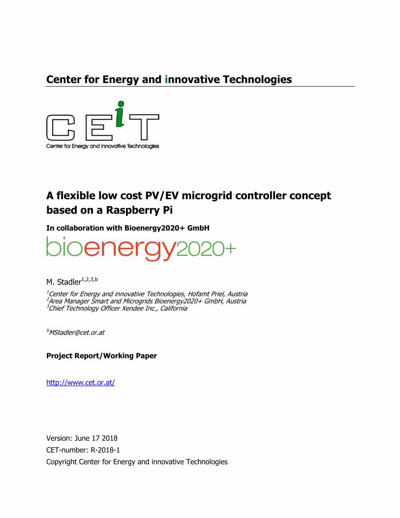
Figure 3: Operational wireless enabled Raspberry Pi controller (small black box on the right) with the controller modules running (small window on the screen).
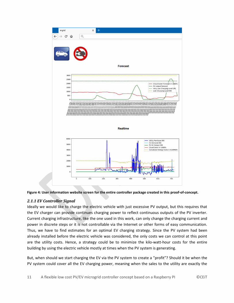
The forecaster module consists of roughly 7000 characters or 180 lines of Python code (including
comments, spaces and empty lines between code) and the major tasks are to a) connect to
wunderground.com and retrieve the json forecast file for the specified location, b) parse through the
returned file and determine the sky cover for the forecasting period, c) calculate the expected PV output
based on the forecasted sky cover and ideal PV output without any clouds for the forecasting period, d)
save the expected PV output for the next days in a csv file so that the forecast upload module can upload
the data to the webserver in the next step. The top of Figure 4 shows an example for February/March
2018 in which the green line represents the forecasted PV output and the red line represents the
forecasted cloud cover. When the “PV output forecast” is near or above the “Very low level charging”
line the EV owner should consider connecting the EV to the socket since this represents our selected
charging level in this proof-of-concept project. Please note that the cloud cover is scaled by a factor 10 to
fit the diagram. The top figure of Figure 4 indicates that charging via the PV system will be attractive on
March 1st.
The forecast upload module consists of roughly 2900 characters or 105 lines of Python code (including
comments, spaces and empty lines between code). The Python code for the forecast upload module
Page 9
9 A flexible low cost PV/EV microgrid controller concept based on a Raspberry PI ©CEiT
basically creates a plot of the forecast, based on the csv file, by using python’s matplotlib and uploading
it to a webserver via the python library ftplib.
The real-time data collection and control signal module is the most sophisticated python module
required for this project. It consists of roughly 12600 characters or 390 lines of Python code (including
comments, spaces and empty lines between code) and the major tasks are to a) collect the current sky
cover for data logging and future self-learning algorithms3, b) collect the actual power demand from the
EV power meter, c) collect the actual building demand from the bi-directional power meter, d) collect
the PV output from the PV inverter, e) calculate the controller signals (see also section 2.1.1 EV
Controller Signal), f) and create and or update the central csv database file for data logging and to allow
the real-time figure upload module to create graphs and also the EV communication module to send
information to the EV. All python modules are programmed in a way to allow simple adjustment and
scalability to other sites. In the case of the real-time data collection and control signal module the
initialization section holds for example following information: 1) http addresses of the power meters or
the weather website, 2) usernames and passwords for the power meter built-in accounts, 3) strings to
identify the relevant information on the power meters and PV inverter since web-scraping techniques
are programmed to find the relevant information, 4) electricity purchase and sales prices and other
building relevant information to calculate the EV controller signals. The real-time data collection and
control signal module does not communicate with the EV directly and the communication has been
implemented via the EV communication module. Thus, all information collected and calculated by the
controller is stored in a central database (in our case a csv file) with 16 entries/columns, holding
important information as for example car connected to the building? Controller Override? First of all, the
controller should only control the EV when it is connected to the building. This can be determined by the
standby current of the EV. If the car is connected to the EV charging cable the EV power meter will detect
a small standby power of roughly 4 W. If the controller does not detect at least an EV power demand of 4
W there is no car connected to the building and the controller will write a “0” into the database, and
thus, the EV communication module will not attempt any communication with the EV. This is important
since we do not want to interfere with any ongoing charging of the EV at other sites or external charging
stations. Another important feature is fast charging, which should be able at the building at any time
without any controller restrictions. Thus, the controller is designed to control only one level of charging.
In our case 2300 W has been selected as the controllable level (“Very Low charging Level” from Figure 4).
If the car owner wants to charge at any time he/she just selects a higher charging level on the charging
cable settings and the controller will initiate a “Controller Override” and the EV communication module
will also not interfere with the charging. The objective of the controller is to minimize the energy costs at
the building (see next section).
The real-time data collection and control signal module runs in a 1 min loop and shorter loops could be
set, which will be important in the future when islanded microgrids should be considered and faster
response is required.
3 To improve the forecasting and build the ideal PV output table for the forecaster module.
Page 10
10 A flexible low cost PV/EV microgrid controller concept based on a Raspberry PI ©CEiT
The EV communication module consists of roughly 5250 characters or 150 lines of Python code (including
comments, spaces and empty lines between code) and the major task is to automatically login to the EV
web application and retrieve a security token to perform the charging and discharging operations in an
automated and encrypted fashion. To achieve this, the Vehicle Identification Number (VIN) is used to
establish a secured communication with the proper car. Whenever there is a change in the central csv
database (see Figure 4) regarding the charging signal, the EV communication module will send the
changes to the EV web application via post requests from the python request library. To minimize the
traffic between the Raspberry Pi EV communication module and the EV web application only changes in
the charging state are sent to the EV website and then to the car, identified by the VIN.
The last module used in the controller is the “real-time figure upload module”, which creates a figure of
the real-time building demand, EV demand, PV output and other parameters. The module consists of
roughly 5800 characters or 190 lines of Python code (including comments, spaces and empty lines
between code).
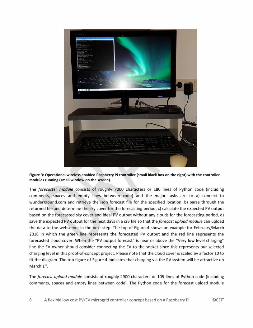
To inform the car owner a user information screen is created by the modules and displaced on a website.
This is the only information and interaction point for the user, and thus, creates a very user-friendly
environment (see Figure 4). At the top are two icons indicating if the car is connected to the microgrid
and if the EV is charged (in our example no charging happens since the battery icon is crossed out). The
top diagram in Figure 4 is the forecast uploaded by the forecast upload module and the diagram at the
bottom is the real-time figure indicating the conditions of the system, created by the real-time figure
upload module. The forecast indicates that connecting the EV on February 28th might be beneficial and
March 1st looks very promising for controlled EV charging. The real-time figure is the most complicated
diagram and the dark blue line is the total demand purchased from the utility. The spikes around time-
step 400 to 500 indicate electric cooking at noon. The green line is the PV output and since the figure
shows a snowy winter day there is only limited PV output, which also is reflected by the dashed yellow
line. The dashed yellow line is the actual kWh cost as described in the next section and it is always
higher than the charging threshold kWh cost 1. The turquoise line is the EV charging and there is no
charging all day long, except a tiny spike at time-step 700. The car was not connected all day long and at
time-step 700 the car was connected and started charging, but since the costs are not favorable the
controller turned off the charging immediately. Finally, the red line is the observed sky cover. To fit the
diagram nicely it is shown in 10 times 100% and 100% sky cover is equal 1000% in Figure 4.
Page 11
11 A flexible low cost PV/EV microgrid controller concept based on a Raspberry PI ©CEiT
Figure 4: User information website screen for the entire controller package created in this proof-of-concept.
2.1.1 EV Controller Signal
Ideally we would like to charge the electric vehicle with just excessive PV output, but this requires that
the EV charger can provide continues charging power to reflect continuous outputs of the PV inverter.
Current charging infrastructure, like the one used in this work, can only change the charging current and
power in discrete steps or it is not controllable via the Internet or other forms of easy communication.
Thus, we have to find estimates for an optimal EV charging strategy. Since the PV system had been
already installed before the electric vehicle was considered, the only costs we can control at this point
are the utility costs. Hence, a strategy could be to minimize the kilo-watt-hour costs for the entire
building by using the electric vehicle mostly at times when the PV system is generating.
But, when should we start charging the EV via the PV system to create a “profit”? Should it be when the
PV system could cover all the EV charging power, meaning when the sales to the utility are exactly the
Page 12
12 A flexible low cost PV/EV microgrid controller concept based on a Raspberry PI ©CEiT
power demand for the EV charger or is it possible that we could start at lower PV output levels when we
still have to purchase some energy from the utility?
We define following objective function for the controller: Charge the EV in a way to reduce the kilo-watt
hour costs for all consumed energy at the building, including the energy for EV charging.
To follow this objective, it is necessary to calculate the kilo-watt hour costs for the building without the
electric vehicle.
kwh cost 1=
utility demand ∙purchase price - sales to the utility ∙sale price
electricity demand building
= €0.096/kWh
Equation 1
with
utility demand = 2900 kWh/year
sales to the utility=2900 kWh/year
electricity demand building= 4230 kWh/year
purchase price= €0.2/kWh
sales price= €0.06/kWh
Now, how would the most optimal charging strategy look like? Since we are not controlling the building
itself, the best the controller could do is to charge the EV with PV energy only. In this case, we could
achieve following kilo-watt hour costs for the building, including the EV demand.
kWh cost 2
=utility demand ∙purchase price - {sales to the utility -EV charging }∙sale price
total electricity demand
= €0.086/kWh
Equation 2
with
utility demand = 2900 kWh/year (utility demand without EV)
sales to the utility=2900 kWh/year (without EV)
EV charging = 1700 kWh/year4
total electricity demand = 5930 kWh/year (including EV)
The worst case would be if all additional electricity for the EV were to be purchased from the utility.
4 This is based on real driving data from the electric vehicle which is used 10,000 km a year and consumes
17kWh/100km on average.
Page 13
13 A flexible low cost PV/EV microgrid controller concept based on a Raspberry PI ©CEiT
kWh cost 3
={utility demand + EV charging}∙purchase price - sales to the utility ∙sale price
total electricity demand
= €0.126/kWh
Equation 3
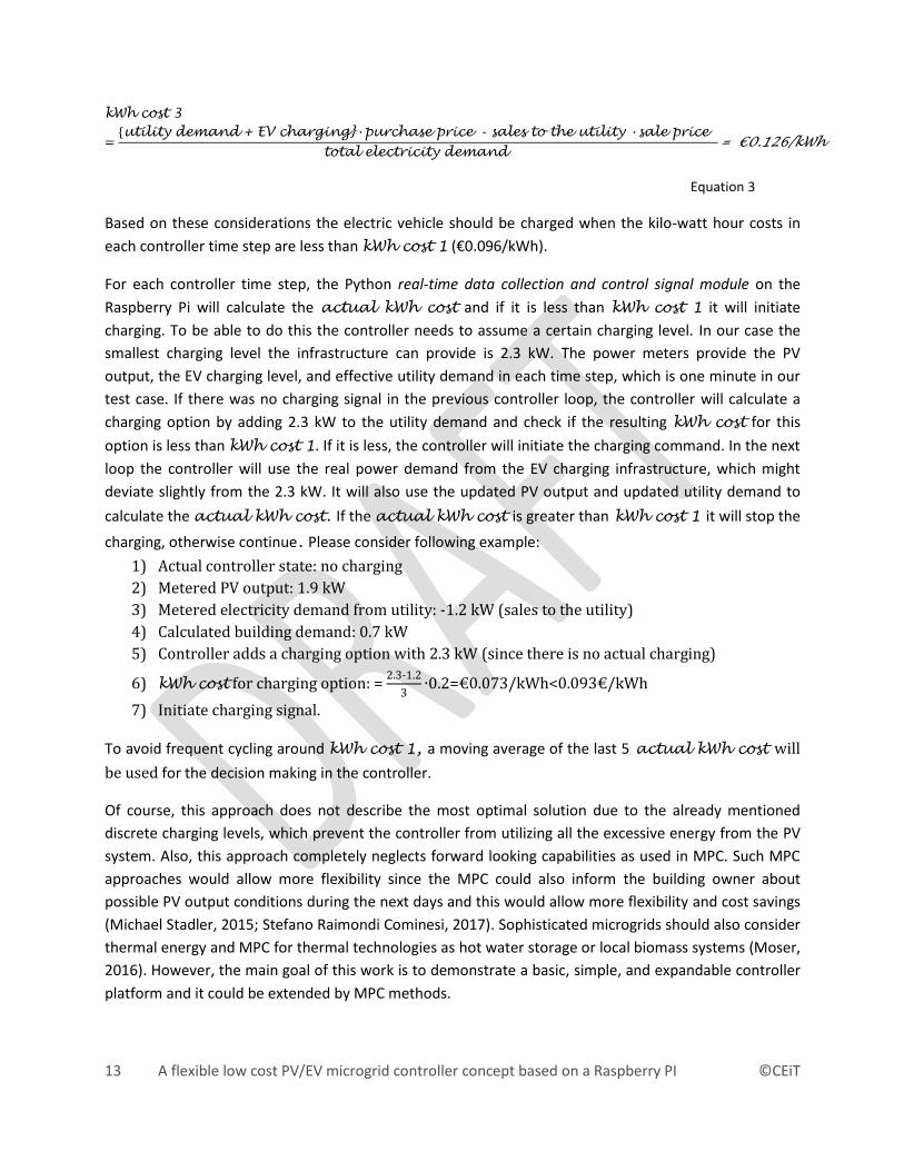
Based on these considerations the electric vehicle should be charged when the kilo-watt hour costs in
each controller time step are less than kWh cost 1 (€0.096/kWh).
For each controller time step, the Python real-time data collection and control signal module on the
Raspberry Pi will calculate the actual kWh cost and if it is less than kWh cost 1 it will initiate
charging. To be able to do this the controller needs to assume a certain charging level. In our case the
smallest charging level the infrastructure can provide is 2.3 kW. The power meters provide the PV
output, the EV charging level, and effective utility demand in each time step, which is one minute in our
test case. If there was no charging signal in the previous controller loop, the controller will calculate a
charging option by adding 2.3 kW to the utility demand and check if the resulting kWh cost for this
option is less than kWh cost 1. If it is less, the controller will initiate the charging command. In the next
loop the controller will use the real power demand from the EV charging infrastructure, which might
deviate slightly from the 2.3 kW. It will also use the updated PV output and updated utility demand to
calculate the actual kWh cost. If the actual kWh cost is greater than kWh cost 1 it will stop the
charging, otherwise continue. Please consider following example:
1) Actual controller state: no charging
2) Metered PV output: 1.9 kW
3) Metered electricity demand from utility: -1.2 kW (sales to the utility)
4) Calculated building demand: 0.7 kW
5) Controller adds a charging option with 2.3 kW (since there is no actual charging)
6) kWh cost for charging option: = 2.3-1.2
3∙0.2=€0.073/kWh<0.093€/kWh
7) Initiate charging signal.
To avoid frequent cycling around kWh cost 1, a moving average of the last 5 actual kWh cost will
be used for the decision making in the controller.
Of course, this approach does not describe the most optimal solution due to the already mentioned
discrete charging levels, which prevent the controller from utilizing all the excessive energy from the PV
system. Also, this approach completely neglects forward looking capabilities as used in MPC. Such MPC
approaches would allow more flexibility since the MPC could also inform the building owner about
possible PV output conditions during the next days and this would allow more flexibility and cost savings
(Michael Stadler, 2015; Stefano Raimondi Cominesi, 2017). Sophisticated microgrids should also consider
thermal energy and MPC for thermal technologies as hot water storage or local biomass systems (Moser,
2016). However, the main goal of this work is to demonstrate a basic, simple, and expandable controller
platform and it could be extended by MPC methods.
Page 14
14 A flexible low cost PV/EV microgrid controller concept based on a Raspberry PI ©CEiT
2.2 Communication Infrastructure and Hardware Implementation
It was a challenge to retrieve real-time load data for the entire building (bi-directional power meter in
Figure 1). The building is equipped with a smart meter owned by the public utility, but the regulation in
Austria is lacking behind other countries and there is no legislation in place which regulates real-time
data exchange between the utility owned smart meter and the building owner. Thus, the decision was to
use a separate metering unit. However, most cheap metering technologies are running on propriety
protocols without any direct IP enabled on-board web-server for direct Internet of Things (IoT)
communication. There are only a limited number of IP enabled metering devices available, and
therefore, most of the hardware costs were spent on the two IP enabled power meters, which results in
45% of the total equipment and engineering costs from Table 2. Since it was necessary to use a separate
power meter for the entire building, it was also necessary to hire a licensed electrical contractor to install
the power meter in the switchbox (see also Figure 5). That electrical engineer had to upgrade cables for
the EV charging to enable fast charging too. Those engineering costs are roughly 38% of the total
contracted engineering and equipment costs from Table 2.
Figure 5: Bi-directional power meter (small black box at the top) and P-Lan (grey box that connects to the bi-directional power meter) in the switchbox.
Figure 6: Main switch (at the top), EV power meter (black box in open casing), P-Lan unit (grey box which connects via network cable to the EV power meter), and charging cable for EV (red socket with blue cable).
Page 15
15 A flexible low cost PV/EV microgrid controller concept based on a Raspberry PI ©CEiT
The integration of the power meters and the PV inverter in the Power-Lan communication infrastructure
does not require a licensed technician. It was also necessary to mount a casing for the EV power meter
and to add a main switch to allow complete disconnection of the EV charging unit. This work does not
require a skilled engineer either (see also Figure 6). Figure 6 also shows the blue charging cable at the
bottom, which needs to be plugged into the car for charging. That blue cable is attached to a “smart”
device which allows selecting the different charging levels. The “smart” device, which is not shown in the
figure to avoid any indirect support for that equipment manufacturer can provide charging levels up to
22 kW by just pressing an associated button. If the car owner wants that the Python controller manages
the charging he/she just selects the selected controllable level (in our case the 2.3 kW, see also the
description of the real-time data collection and control signal module in the previous section).
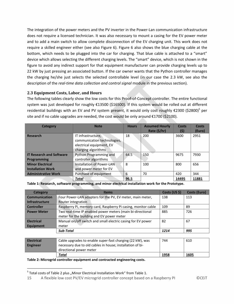
2.3 Equipment Costs, Labor, and Hours
The following tables clearly show the low costs for this Proof-of-Concept controller. The entire functional
system was just developed for roughly €13500 ($16500). If this system would be rolled out at different
residential buildings with an EV and PV system present, it would only cost roughly €2300 ($2800)5 per
site and if no cable upgrades are needed, the cost would be only around €1700 ($2100).
Category Note Hours Assumed Hourly Rate ($/hr)
Costs ($)
Costs (Euro)
Research IT infrastructure, communication technologies, electrical equipment, EV charging algorithms
18 200 3600 2951
IT Research and Software Programming
Python Programming and controller algorithms
64.5 150 9675 7930
Minor Electrical Installation Work
Installation of Power-LAN and power meter for EV
8 100 800 656
Administrative Work Purchase of equipment 6 70 420 344
Total 96.5 14495 11881
Table 1: Research, software programming, and minor electrical installation work for the Prototype.
Category Items Costs (US $) Costs (Euro)
Communication Infrastructure
Four Power-LAN adapters for the PV, EV meter, main meter, Router integration
138 113
Controller Raspberry Pi, memory card, Raspberry Pi casing, monitor cable 109 89
Power Meter Two real-time IP enabled power meters (main bi-directional meter for the building and EV power meter
885 726
Electrical Equipment
Manual on/off switch and small electric casing for EV power meter
82 67
Sub-Total 1214 995
Electrical Engineer
Cable upgrades to enable super-fast charging (22 kW), was necessary due to old cables in house; installation of bi-directional power meter
744 610
Total 1958 1605
Table 2: Microgrid controller equipment and contracted engineering costs.
5 Total costs of Table 2 plus „Minor Electrical Installation Work“ from Table 1.
Page 16
16 A flexible low cost PV/EV microgrid controller concept based on a Raspberry PI ©CEiT
Of course, these costs do not consider any maintenance service, liability costs, or major changes to the
Python code at a major product roll-out. However, since the Python code was programmed in a modular
way, simple adjustments and modifications like IP address changes, energy prices, etc. can be handled in
minutes.
3 Test runs
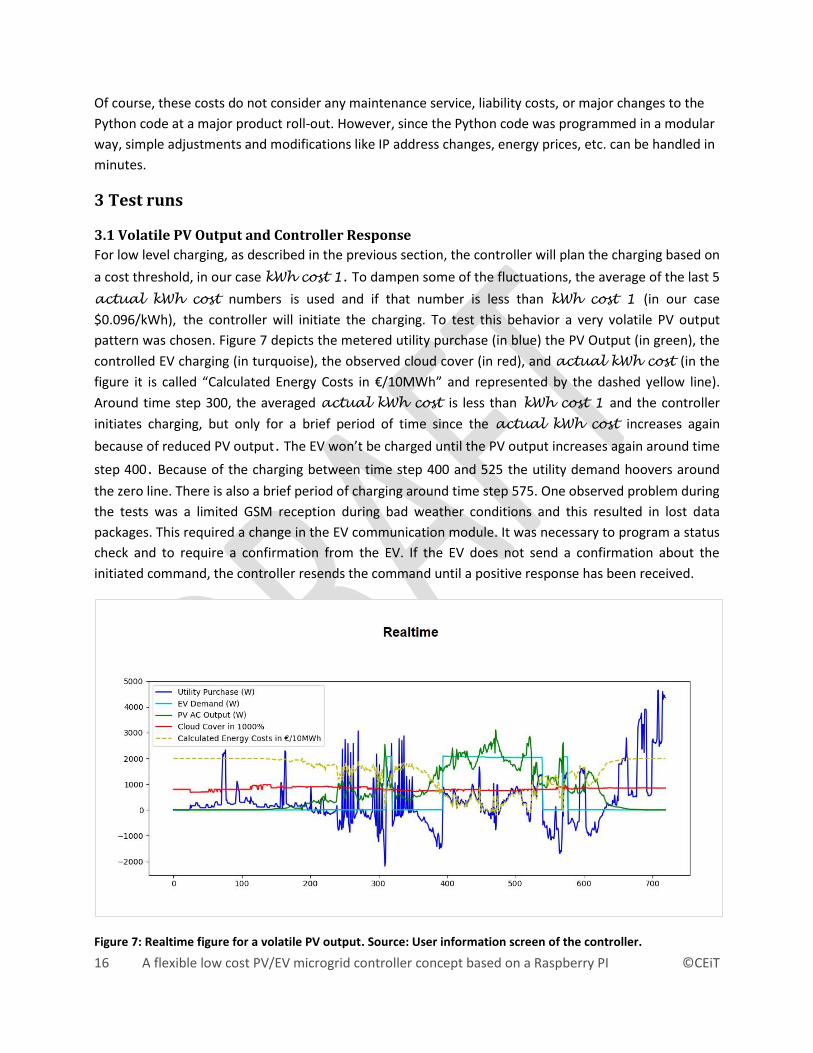
3.1 Volatile PV Output and Controller Response
For low level charging, as described in the previous section, the controller will plan the charging based on
a cost threshold, in our case kWh cost 1. To dampen some of the fluctuations, the average of the last 5
actual kWh cost numbers is used and if that number is less than kWh cost 1 (in our case
$0.096/kWh), the controller will initiate the charging. To test this behavior a very volatile PV output
pattern was chosen. Figure 7 depicts the metered utility purchase (in blue) the PV Output (in green), the
controlled EV charging (in turquoise), the observed cloud cover (in red), and actual kWh cost (in the
figure it is called “Calculated Energy Costs in €/10MWh” and represented by the dashed yellow line).
Around time step 300, the averaged actual kWh cost is less than kWh cost 1 and the controller
initiates charging, but only for a brief period of time since the actual kWh cost increases again
because of reduced PV output. The EV won’t be charged until the PV output increases again around time
step 400. Because of the charging between time step 400 and 525 the utility demand hoovers around
the zero line. There is also a brief period of charging around time step 575. One observed problem during
the tests was a limited GSM reception during bad weather conditions and this resulted in lost data
packages. This required a change in the EV communication module. It was necessary to program a status
check and to require a confirmation from the EV. If the EV does not send a confirmation about the
initiated command, the controller resends the command until a positive response has been received.
Figure 7: Realtime figure for a volatile PV output. Source: User information screen of the controller.
Page 17
17 A flexible low cost PV/EV microgrid controller concept based on a Raspberry PI ©CEiT
3.2 Fast Charging Detection and Controller Override
Figure 8: Realtime figure with fast charging. Source: User information screen of the controller.
An important feature of the POC Python controller is to manage the charging process at a certain
charging level only (in our case 2.3 kW) and not to interfere with the charging at higher charging levels or
when the car is not connected to the building. Figure 8 demonstrates that behavior. The EV was not
connected to the building until around time step 500. Because of favorable conditions the controller
initiated charging as the EV became connected to the building and initiated the stop charging command
around time step 675. Right after that a higher charging level was selected by the car owner at the
“smart” charging cable to completely charge the EV at any charging costs. The real-time data collection
and control signal module detected that higher charging power of 8 kW and did not interfere with the
charging since it sent a controller override to the central database and this means that the EV
communication module will not interfere with the charging. As the EV battery was fully charged, the EV
stop-charging automatically.
4 Conclusions The main objective of this work has been to demonstrate a low costs and basic controller concept based
on standardized hardware communication products and expandable Python software modules which are
running on a cheap Raspberry PI to control the charging process of an EV. That battery charging will be
controlled only when the EV is connected to the building with the objective to minimize charging costs
and support the electricity generation from the onsite PV system. This work is driven by the fact that
expensive communication hardware and proprietary communication protocols and infrastructure limit
the penetration of new and innovative technologies in microgrids. Furthermore, sophisticated controller
algorithms cannot be deployed if it requires customized engineering for each microgrid. Thus, the
demonstrated concept should be understood as a basic test case that will be expended by MPC and AI
algorithms in the future. The designed concept is open enough to consider other technologies as
Page 18
18 A flexible low cost PV/EV microgrid controller concept based on a Raspberry PI ©CEiT
stationary storage without major changes to the code and communication. The Proof-of-Concept
platform will be used as testbed for future research.
The work clearly demonstrates that it is possible to design such a Proof-of-Concept controller for €13500
($16500) and a roll-out of such a controller can be as cheap as €1700 ($2100). Focusing on the hardware
costs of such a controller concept it becomes clear that the hardware can be cheaper than €1000
($1200), creating a reference point for any commercial communication, data infrastructure, and smart
controller hardware in a residential or small commercial microgrid.
It has been proven that the controller works reliable and the next steps are the integration of MPC and
AI methods to create forward looking predictive capabilities. Another focus of research will be the
consideration of islanded conditions, which will create interesting challenges due to active and reactive
power aspects and fast response times.
Acknowledgment This work has been supported by the Center for Energy and innovative Technologies (CEiT) by providing
some of the hardware required for this project. The technology and controller development has been
supported by CEiT too. Literature Research for this paper has been supported by a grant from the Lower
Austrian government and Bioenergy2020+ GmbH.
References Aymen Chaouachi, R. M. (April 2013). Multiobjective Intelligent Energy Management for a Microgrid.
IEEE Transactions on Industrial Electronics, 60, 1688-1699.
Björn Nykvist, M. N. (2015). Rapidly falling costs of battery packs for electric vehicles. Nature Climate
Change, 329–332.
California Public Utilities Comission. (2017, 05). Consumer and Retail Choice, the Role of the Utility and an
Evolving Regulatory Framework. Retrieved 01 21, 2018, from White Paper:
http://www.cpuc.ca.gov/uploadedFiles/CPUC_Public_Website/Content/News_Room/News_and
_Updates/Retail%20Choice%20White%20Paper%205%208%2017.pdf
Cardoso G., M. S.-P. (October 2013). Microgrid Reliability Modeling and Battery Scheduling Using
Stochastic Linear Programming. Journal of Electric Power Systems Research, 103, 61-69.
Dan Ton, J. R. (2017). Microgrid Controller Initiatives: An Overview of R&D by the U.S. Department of
Energy. IEEE Power and Energy Magazine, 15(4), 24-31.
Dan Ton, M. A. (October 2012). The U.S. Department of Energy’s Microgrid Initiative. The Electricity
Journal, 25(8), 84-94.
Eto, J. H. (2015, October 9). The CERTS Microgrid, BNL Smart Grid Workshop. Retrieved 02 12, 2018, from
https://www.bnl.gov/sgw2015/files/talks/Eto.pdf
Page 19
19 A flexible low cost PV/EV microgrid controller concept based on a Raspberry PI ©CEiT
European Commission. (2017, 12 08). Retrieved 01 22, 2018, from Legal sources on renewable energy:
http://www.res-legal.eu/search-by-country/austria/single/s/res-e/t/promotion/aid/feed-in-
tariff-green-electricity-act/lastp/94
Farid Katiraei, A. Z. (2017). Microgrid Control Systems: A Practical Framework [In My View]. IEEE Power
and Energy Magazine, 15(4).
G. Y. Morris, C. A. (12. 11 2012). Evaluation of the costs and benefits of Microgrids with consideration of
services beyond energy supply. Power and Energy Society General Meeting. San Diego: IEEE.
GoSolarCalifornia. (2018). Retrieved 01 21, 2018, from GoSolarCalifornia:
http://www.gosolarcalifornia.ca.gov/solar_basics/net_metering.php
Michael Stadler, S. M. (2015). Supervisory Controller for PV and Storage. Retrieved 01 21, 2018, from
Lawrence Berkeley National Laboratory: http://eta-
publications.lbl.gov/sites/default/files/supervisory_controller_for_pv_and_storage.pdf
Michael Zachar, P. D. (2016). Nonlinear Economic Model Predictive Control for Microgrid Dispatch. IFAC-
PapersOnLine, 49(18), 778-783.
Moser, A. (2016). Model predictive control of a bidirectional, solar and biomass-based district heating
grid. Graz University of Technology,
https://www.researchgate.net/publication/320249847_Model_predictive_control_of_a_bidirect
ional_solar_and_biomass-based_district_heating_grid.
Naïm Darghouth, G. B. (2010). The Economic Value of PV and Net Metering to Residential Customers in
California. SOLAR 2010 Conference Proceedings, National Solar Conference. Phoenix: American
Solar Energy Society (ASES).
Net Energy Metering (NEM). (2016). Retrieved 01 21, 2018, from California Public Utilities Commission:
http://www.cpuc.ca.gov/General.aspx?id=3800
O. Schmidt, A. H. (2017). The future cost of electrical energy storage based on experience rates. Nature
Energy, Article number: 17110.
R. H. Lasseter, J. H. (2011). CERTS Microgrid Laboratory Test Bed. IEEE Transactions on Power Delivery,
26, 325 - 332.
Stadler Michael, G. C. (2016). Value streams in microgrids: A literature review. Applied Energy, 162, 980-
989.
Stefano Raimondi Cominesi, M. F. (2017). A Two-Layer Stochastic Model Predictive Control Scheme for
Microgrids. IEEE Transactions on Control Systems Technology, 26(1), 1-13.
U.S Department of Energy Berkeley Lab. (2017). Retrieved 02 12, 2018, from building-microgrids:
https://building-microgrid.lbl.gov/microgrid-definitions