A Frances: A Tool For Understanding Computer Architecture and Assembly Language TYLER SONDAG, Intel Labs † KIAN L. POKORNY, McKendree University HRIDESH RAJAN, Iowa State University Categories and Subject Descriptors: K.3.0 [Computers and Education]: General; C.0 [Computer Systems Organization]: General—Modeling of computer architecture General Terms: Education, Languages, Compiler, Architecture Additional Key Words and Phrases: Frances, Visualization, Architecture, Code Generation, Compilers ACM Reference Format: Sondag, T., Pokorny, K.L., Rajan, H. 2011. Frances: A Tool For Understanding Computer Architecture and Assembly Lan- guage ACM V, N, Article A (January YYYY), 28 pages. DOI = 10.1145/0000000.0000000 http://doi.acm.org/10.1145/0000000.0000000 1. INTRODUCTION Fundamental to computing are the concepts of software and hardware. Most computer science courses concentrate on a high level of abstraction. Introductory programming courses focus on high-level languages and their abstractions. Likewise, algorithm courses are often implementation independent to focus on core mathematical principles. These abstractions are crucial to reducing The work described in this article is a revised and extended version of our papers presented at SIGCSE 2010 and CCSC 2011. Sondag and Rajan were supported in part by the US National Science Foundation under grants CNS-06-27354, CNS- 07-09217, CCF-08-46059, and CCF-11-17936. † This article describes work that was done while at Iowa State University. Author’s address: T. Sondag, Intel Corporation, 2200 Mission College Blvd, Santa Clara, CA 95054. K.L. Pokorny, Division of Computing, McKendree University, 701 College Road, Lebanon, IL 62254. H. Rajan, Dept. of Computer Science, Iowa State University, 226 Atanasoff Hall, Ames, IA 50014. Permission to make digital or hard copies of part or all of this work for personal or classroom use is granted without fee provided that copies are not made or distributed for profit or commercial advantage and that copies show this notice on the first page or initial screen of a display along with the full citation. Copyrights for components of this work owned by others than ACM must be honored. Abstracting with credit is permitted. To copy otherwise, to republish, to post on servers, to redistribute to lists, or to use any component of this work in other works requires prior specific permission and/or a fee. Permissions may be requested from Publications Dept., ACM, Inc., 2 Penn Plaza, Suite 701, New York, NY 10121-0701 USA, fax +1 (212) 869-0481, or [email protected]. c YYYY ACM 0000-0000/YYYY/01-ARTA $10.00 DOI 10.1145/0000000.0000000 http://doi.acm.org/10.1145/0000000.0000000 ACM Journal Name, Vol. V, No. N, Article A, Publication date: January YYYY.
Transcript
A
Frances: A Tool For Understanding Computer Architecture andAssembly Language
TYLER SONDAG, Intel Labs†
KIAN L. POKORNY, McKendree UniversityHRIDESH RAJAN, Iowa State University
Students in all areas of computing require knowledge of the computing device including software implemen-
tation at the machine level. Several courses in computer science curricula address these low-level details
such as computer architecture and assembly languages. For such courses, there are advantages to studying
real architectures instead of simpli�ed examples. However, real architectures and instruction sets introduce
complexity that makes them di�cult to grasp in a single semester course. Visualization techniques can help
ease this burden, unfortunately existing tools are often di�cult to use and consequently di�cult to adopt
in a course where time is already limited. To solve this problem, we present Frances. Frances graphically
illustrates key di�erences between familiar high-level languages and unfamiliar low-level languages and also
illustrates how familiar high-level programs behave on real architectures. Key to this tool is that we use a
simple web interface that requires no setup, easing course adoption hurdles. We also include several features
that further enhance its usefulness in a classroom setting. These features include graphical relationships
between high-level code and machine code, clearly illustrated step by step machine state transitions, color
coding to make instruction behavior clear, and illustration of pointers. We have used Frances in courses and
performed experimental evaluation. Our experiences with Frances in the classroom demonstrate its usabil-
ity. Most notably, in our experimental setting, students with no computer architecture course experience
were able to complete lessons using Frances with no guidance.
Categories and Subject Descriptors: K.3.0 [Computers and Education]: General; C.0 [Computer Systems Organization]:General—Modeling of computer architecture
General Terms: Education, Languages, Compiler, Architecture
Additional Key Words and Phrases: Frances, Visualization, Architecture, Code Generation, Compilers
ACM Reference Format:Sondag, T., Pokorny, K.L., Rajan, H. 2011. Frances: A Tool For Understanding Computer Architecture and Assembly Lan-guage ACM V, N, Article A (January YYYY), 28 pages.DOI = 10.1145/0000000.0000000 http://doi.acm.org/10.1145/0000000.0000000
1. INTRODUCTIONFundamental to computing are the concepts of software and hardware. Most computer sciencecourses concentrate on a high level of abstraction. Introductory programming courses focus onhigh-level languages and their abstractions. Likewise, algorithm courses are often implementationindependent to focus on core mathematical principles. These abstractions are crucial to reducing
DOI 10.1145/0000000.0000000 http://doi.acm.org/10.1145/0000000.0000000
ACM Journal Name, Vol. V, No. N, Article A, Publication date: January YYYY.
A:2 Sondag, Pokorny, and Rajan
the complexity of the problems at hand and help students understand the material and core conceptsin a semester’s time. However, students in any field of computing must have an understanding, atvarious levels of abstraction, of the computing devices and the software programs that run them.
1.1. BackgroundThere are typically two courses that are critical in helping students understand the connections be-tween software and hardware: computer architecture (organization) and compiler (language) design.
1.1.1. Computer Architecture. The 2008 curriculum revision for computer science states, “A pro-fessional in any field of computing should not regard the computer as just a black box that executesprograms by magic... Students need to understand computer architecture in order to make best useof the software tools and computer languages they use to create programs [CC 2008, pp. 49].” Thestudy of a computer architecture, its behavior, and instruction set are typical components to a com-puter organization and architecture course.
1.1.2. Language Implementation. Compiler and language implementation courses appear in allrevisions of the ACM Computing Curricula. The latest revision of CC ’01 states the importance ofthese topics: “. . . good compiler writers are often seen as desirable; they tend to be good softwareengineers [CC 2008, pp.11].” These compiler design and programming language courses typicallyinvolve language translation from high to low-level languages (typically an assembly language).
Aside from these courses, while most students will never write assembly code directly, under-standing the code generated by compilers is important for both programming and debugging tasks.
1.2. ProblemsIn the past, courses on architecture, compilers, and programming language design were often sup-ported by a prerequisite chain containing courses on assembly and low-level programming lan-guages. However, in recent years these prerequisite courses have slowly been supplanted by othertopics in many undergraduate computing curricula [Loui 1988]. As a result of this typical curriculadesign, students have little exposure to these low-level details when they reach courses like com-puter architecture or compiler design. Thus, not only must students learn these new topics, whichdiffer from anything they have learned before, they must also continue to learn other complex top-ics introduced in these courses (e.g. architecture, language design, etc.). Therefore, there is a realneed to enhance methods and techniques for teaching students assembly language and low-levelprogramming topics.
For learning and teaching these difficult topics, it is desirable to use interactive tools that havebeen shown to be highly effective for education [Naps et al. 2002; Hundhausen 2002]. Many toolsexist for visualizing programs [Aiken 1996; Corliss and Lewis 2008; Resler and Deaver 1998] andsimulating programs on different architectures [Coe et al. 1995; Nikolic et al. 2009; Null and Lobur2003; Graham 1985; Braught and Reed 2001; Borunda et al. 2006]. However, they are typicallytime consuming to learn and difficult to use. As a result, adopting them in a course is challenging.Especially in the presence of all the other new material that must be learned.
1.3. ContributionsTo solve these problems, we present the Frances tool1. A major idea behind our approach is totake advantage of the students’ existing knowledge of high-level language programming. Thus,the Frances tool allows students to enter familiar high-level code that is then shown alongside agraphical representation of the assembly code and machine state. We make use of several novelfeatures to help students make connections between high-level programming languages, assemblylanguage, and the low-level architectural concepts of the computing device. In summary, Frances
1We named the tool Frances in honor of Frances E. Allen . She received the Turning award for pioneering contributionsto the theory and practice of optimizing compiler techniques that laid the foundation for modern optimizing compilers andautomatic parallel execution.
ACM Journal Name, Vol. V, No. N, Article A, Publication date: January YYYY.
Frances: A Tool For Understanding Computer Architecture and Assembly Language A:3
— presents a visualization of the low-level code that maintains actual target code ordering,— differentiates between types of run-time paths in the low-level code,— color codes instruction blocks by their high-level control constructs,— shows how each individual machine instruction impacts the machine state,— displays the components of the system state in a logical organization, illustrating several important
concepts,— allows for both forward and backward stepping through program steps, which allows students to
revisit complicated steps and processes,— color codes individual parts of the machine state making the impact of each instruction clear,— clearly illustrates difficult concepts surrounding addresses (e.g. pointers and stack) using color
coded arrows.
Thus, we have designed Frances to help students understand low-level languages, language transla-tion (code generation), and computer architecture by showing how familiar high-level code maps tolow-level code and how that low-level code behaves on a target architecture.
1.3.1. Ease of Adoption. We have developed Frances in a way such that it is platform independent,requires no setup, and is trivial to begin using. By providing our simple web-based interface thatis easy to learn, we avoid three of the four biggest factors hindering adoption of such visualizationtools in educational settings2 namely time to learn the new tool, time to develop visualizations, andlack of effective development tools (we also eliminate other large problems such as reliability andinstall issues) [Naps et al. 2002]. We believe that all of this together makes Frances easy to adopt,use, and understand.
Fig. 1. Worldwide usage of Frances between April2009 (initial release) and January 2012. USA traffic isexcluded.
Fig. 2. Frances usage within the US since between April2009 (initial release) and January 2012. Traffic from the au-thors and their students is excluded.
To further facilitate adoption, Frances is freely disseminated for educational purposes (http://frances.cs.iastate.edu) and at this time we know of several educators around the worldthat have tried out our tool since its public release showing its potential. Figures 1 and 2 show useof the Frances tool between its public release in April 2009 until January 2012 (excluding use bythe authors and their students). Figure 1 shows a world map where countries highlighted with greenrepresent those trying out our Frances tool (this figure excludes traffic from USA). Figure 2 showsa map of the USA where states highlighted with green represent those trying out our Frances tool(this figure excludes traffic from the authors and their students). These figures help demonstrate thewide dissemination, usefulness, and ease of adoption of Frances.
2We solve the fourth problem by making interesting examples (as lessons) available on Frances’s website.
ACM Journal Name, Vol. V, No. N, Article A, Publication date: January YYYY.
A:4 Sondag, Pokorny, and Rajan
1.3.2. Usefulness. We have used Frances in three undergraduate courses and have performedevaluations of the tool, to determine its ease of use and usefulness, independent of any particularcourse. Overall, we observed encouraging results. Students found the tool useful for learning topicsregarding code generation and often used it as a reference when implementing their own compilers.Based on this experience, Frances has been made a more integral part of these courses. Experimen-tatal evaluation of Frances in terms of ease of use and usefulness has shown promise. Even allowingstudents who have never had a computer architecture course to complete the assignments they weregiven with no guidance.
The rest of this paper is organized as follows. Section 2 presents related ideas. Next, Section 3describes our goals when developing the components of Frances. Section 4 describes design andimplementation of the Frances tool. Section 5 describes our experimental results and course experi-ences. Finally, Section 6 discusses future work and concludes.
2. RELATED WORKRelated work can be classified into three major categories: teaching assembly language and lan-guage translation, simulating architectural details and teaching computer architecture, and visualiz-ing programs. We now compare Frances to related work in each of these categories.
2.1. Teaching Assembly Language and Low-Level Language TranslationSince developing a compiler is difficult, especially within a single semester course, a large body ofwork has been done to improve this process. Related work in this area can be broadly classified intotwo categories. The first category is related work dealing with tools designed to help students buildand learn about compilers / language translation systems [Aiken 1996; Corliss and Lewis 2008;Resler and Deaver 1998; Gondow et al. 2010]. Work in the second category deals with teachingassembly language [Zilles 2005; Bredlau and Deremer 2001].
Gondow et al. developed MieruCompiler [Gondow et al. 2010] that is used for visualizing variouspieces related to the source code such as assembly code, abstract syntax tree, symbol table, stacklayout, etc. Our approach differs in that we provide a more visual representation of the assemblycode.
Aiken presented Cool [Aiken 1996], a language and compiler designed for course projects toreduce the overhead for the instructor and keep assignments modular. Similarly, Corliss and Lewisdeveloped Bantam [Corliss and Lewis 2008], a Java compiler project for courses. Modularity isalso achieved in Bantam since components of the compiler can use the provided modules, or beswapped out with custom versions. Rather than developing a new infrastructure, our technique iscomplementary to these existing techniques in order to help understand specific portions of compilerimplementation.
Resler and Deaver propose a visualization tool, VCOCO [Resler and Deaver 1998], for under-standing compilers. VCOCO provides several view panes that show source code, language grammar,compiler, parser, and scanner. Each pane is updated throughout the compilation process. We alsopropose a visual approach, however, we are interested specifically with code generation and presenta graphical approach.
Zilles developed SPIMbot [Zilles 2005]. SPIMbot provides an environment where learning as-sembly is put to use for programming virtual robots. Our approach takes a more traditional approachthat is likely to have less overhead.
Bredlau and Deremer suggest using the Java Virtual Machine (JVM) for teaching assembly [Bred-lau and Deremer 2001]. The idea is to let the Java compiler create JVM code that is compared tothe source code. We take a similar approach but with assembly language and we provide a graphicalcomparison to aid in this process.
2.2. Architectural SimulatorsA large body of work exists for simulating architectures and teaching computer organization andarchitecture [Schwetman 1986; Pai et al. 1997; Coe et al. 1995; Kise et al. 2004; Zeng et al. 2009;
ACM Journal Name, Vol. V, No. N, Article A, Publication date: January YYYY.
Frances: A Tool For Understanding Computer Architecture and Assembly Language A:5
Binkert et al. 2003; Nikolic et al. 2009; Null and Lobur 2003; Graham 1985; Braught and Reed2001; Borunda et al. 2006]. Many of these simulators are targeted toward advanced users. As aresult they are typically very complex and difficult to learn. We now briefly discuss work in thisarea most similar to our introductory computer architecture pedagogical tool.
Null and Lobur developed MarieSIM [Null and Lobur 2003] for use in teaching computer archi-tecture and assembly language. This approach has several advantages including a simple assemblylanguage and an accompanying text book. Similarly, Patt and Patel developed LC-3 [Patt and Patel2004] which makes use of a simple instruction set that is similar to x86. LC-3 also has an acompa-nying text book. However, some argue that there are advantages to using real assembly languagesrather than custom languages [Gondow et al. 2010]. This is a fundamental difference in our ap-proaches. For those who prefer to use a real assembly language we recommend Frances. Further,our work differs in several ways. First, with MarieSIM and LC-3 there is a disconnect betweenhigh-level languages and the low-level instruction set since users must program simulations in thelow-level language. With Frances, students have the option of entering simulations using a varietyof high-level languages (or assembly). Thus, students can see how the system processes code theynormally write and the learning curve for initial use of the tool is very low. Recall that MarieSIMand LC-3 have accompanying text books. This has benefits; however, instructors that have designedtheir courses around different text books may not want to re-design their course around a new book.To help ease the adoption of Frances into existing courses, we develop our course materials aroundtopics that complement existing courses utilizing a standard textbook. Further, Frances is releasedvia the web rather than requiring installation, which hinders adoption because of compatibility anddependence issues. Finally, MarieSIM and LC-3 do not allow “stepping” backwards through pro-gram execution. Frances has this feature to allow students to revisit previous execution steps withoutre-running the entire simulation.
Graham developed “The Simple Computer” simulator [Graham 1985]. Stone later used this sim-ulator to teach CS1 topics [Stone 2006]. Another simulator developed by Braught and Reed is tar-geted toward introductory students in CS0 [Braught and Reed 2001]. The main differences betweenthese works is that (a) Frances has a graphical interface that we believe has a much lower adoptiontime, and (b) Frances uses real instruction set architectures (ISA) rather than custom machines andlanguages.
Borunda et al. developed GSPIM [Borunda et al. 2006], a MIPS simulator, for use in introductorycomputer architecture courses. This tool shows simultaneous views of the program call graph, intra-procedural control flow graph, MIPS assembly code, and registers. Our work differs in that Francesmore easily integrates with both high-level and low-level languages, giving students the ability tovisualize high-level code at a lower level and ease the learning curve. Finally, our control flow graphrepresentations maintain the instruction ordering and layout of actual assembly programs. Thus, webelieve Frances will be more effective when learning assembly language.
2.3. Program VisualizationA large body of work exists for software visualization [Price et al. 1992; McNally et al. 2007;Urquiza-Fuentes and Velázquez-Iturbide 2009; Rössling and Velázquez-Iturbide 2009; Esponda-Arguero 2008; Hundhausen 2002; Naps et al. 2002; Sundararaman and Back 2008; Pauw et al.2002; Reiss 2003; Conway and Pausch 1997; Sanders and Dorn 2003; Wolz et al. 2008; Powerset al. 2006]. Price et al. developed a taxonomy for software visualization [Price et al. 1992]. In thistaxonomy, they make the distinction between algorithm visualization (illustrating high-level abstractcode) and program visualization (illustrating actual code listings). First, rather than illustrating ab-stract algorithms, we focus on illustrating issues such as program implementation, language con-struct behavior, program state, and machine state. Therefore, we consider algorithm visualization tobe complementary to our work on Frances. In terms of program visualization, a major differencebetween our work and previous work is that our interface is much simpler and more straightforward.Thus, we address the primary factor limiting adoption of previous work [Naps et al. 2002]. We areable to do this because Frances’s backend consists of several powerful program analysis techniques.
ACM Journal Name, Vol. V, No. N, Article A, Publication date: January YYYY.
A:6 Sondag, Pokorny, and Rajan
Rather than requiring installation, Frances is deployed via a web interface thus removing additionalhurdles such as software and OS dependencies. Therefore, we avoid many of the factors that hurtadoption of such tools [Naps et al. 2002]. Finally, we developed Frances around a real machineand instruction set rather than custom models thus avoiding a disconnect between the tool and realarchitectures [Gondow et al. 2010].
An example of a program visualization technique is a debugger such as gdb [Free Software Foun-dation 2010], or a graphical debugger such as kdbg [Sixt 2010], etc. Debuggers are very powerfuland expressive tools and as a result are generally difficult to learn to use. Debuggers have severalproblems making them incompatible with program visualization for pedagogical purposes. Theirinterface is typically highly expressive and thus overwhelms introductory students with details. Fur-thermore their interfaces do not visualize program structure. Finally, several aspects of the processmay be confusing for introductory level students such as breakpoints, different techniques for step-ping through execution, modifying program inputs, etc. Our interface is only as expressive as neces-sary for introductory students, avoiding many complex features of debuggers. Finally our interfacehas fixed abstractions that allow us to eliminate issues like breakpoints and different techniques forstepping through execution.
Most similar to our work is the work by Sundararaman and Back on HDPV [Sundararaman andBack 2008], a runtime state visualization tool for C/C++ and Java programs. This work is comple-mentary to our own in two ways. First, the focus of HDPV is on visualization of data structures,whereas our focus is on control flow, system state, and program behavior. Second, they deal withrepresentation concerns for large programs. Since our visualization is more geared toward introduc-tory courses and not advanced courses or software engineering practice, we leave these large scaleconcerns for future work. HDPV uses a machine model that captures low-level details like memorylayout. Since the focus of HDPV is on data structures, it does not trace register values. Registervalues do not appear until moved to memory. For introductory students this can be quite confusing.For example, loop counters often never go beyond registers. Since we focus on classroom use, weaddress this limitation by modeling registers as well as the stack and heap separately. Rather thanfocusing on specific languages, our work currently supports any language that can be compiled tonative code. To enable several low-level implementations, HDPV makes use of Pin [Luk et al. 2005].Similarly, we make use of cross-compilers and GNU BinUtils [Free Software Foundation 2009] tosupport a variety of targets. Frances allows the user to step backward in the code. HDPV does not.
Also similar is IBM’s Jinsight tool [Pauw et al. 2002]. The most important difference from ourwork is that Jinsight focuses on more advanced users and program behavior in terms of perfor-mance. In terms of implementation, Jinsight uses execution traces to develop its visualizations. Ourtool uses a web-based approach. A tool similar to Jinsight was also developed by Reiss [Reiss 2003].This tool, like Jinsight, is targeted towards more experienced programmers and looks at phase be-havior [Sherwood et al. 2002] and performance issues.
3. DESIGN CRITERIA FOR FRANCESIn this section, we discuss the design criteria for developing the Frances tool as well as how weaccomplish these criteria. Briefly, these criteria include making various low-level aspects of com-puting easy to understand for students such as assembly language, computer architecture, and codegeneration. We do this by clearly and quickly showing how familiar high-level language constructstranslate to low-level language code and how this code behaves on the hardware. Additionally, wewant Frances to be easy to learn, require no setup, and not require thorough knowledge of a machinelanguage or computer architecture to get started. Further, we want it to use real architectures andinstruction sets. Next, the tool needs to be effective. To ensure this, we desire a tool that would allowstudents to clearly visualize the behavior of each machine instruction and how familiar high-levelcode maps to this machine code.
ACM Journal Name, Vol. V, No. N, Article A, Publication date: January YYYY.
Frances: A Tool For Understanding Computer Architecture and Assembly Language A:7
3.1. Ease of UseWe felt it was important for Frances to be as easy to use as possible. If not, the cost of learning howto use Frances could easily overshadow the benefits it provides.
We took several steps to make Frances easy to use:
— require no building, setup, or installation,— provide a simple graphical interface with little learning curve,— support a variety of high-level languages, and— support a variety of low-level languages.
This is all necessary to ensure that Frances is feasible for adoption in a single semester withoutdistracting students or drastically changing existing courses.
Because we do not require users to build or set up Frances on their systems, it is faster to beginusing; issues such as software, hardware, or OS dependencies are avoided; and reliability is im-proved. All that is required is a web browser. Users may even access the system on simple devicessuch as cell phones or tablets, which are rapidly gaining popularity.
Many related tools operate from the command line and require the users to learn complicatedsyntax. While powerful and flexible, learning how to use such a tool if it is only planned on beingused for a short period of time is undesirable. We believe our interface is simple enough for users toimmediately begin using it and understanding the output. To facilitate this simple interface, we makeuse of several more complicated analysis techniques on the backend. Further, we rely on graphicalfeatures to show complex properties such as control flow, pointers, changes in state, accesses tomemory locations, etc. This includes a simple logical layout of the system state.
An assumption of our system is that students are familiar with a high-level language. Thus, wehave designed our system to be as easy as possible to integrate a variety of high-level languages.
Another highly important goal was that we did not want to require students to have a thoroughknowledge of machine language to use the tool. Since architecture courses are often the first expo-sure a student has to machine language, we wanted to ease this process as much as possible.
3.2. UsefulnessOne of the main goals of our system to set it apart from others is ease of use, however, usefulnessis still critical. Without it, ease of use is pointless. It has been shown that the way students interactwith visualization tools is more important than the visualization itself [Hundhausen 2002]. Thus,we want a hands-on tool to aid in the learning process. To make this hands-on tool, Frances, useful,we had several goals.
(1) Allow students to step both forward and backward during program visualization. This is a fea-ture that is rare amongst such visualization tools. We believe this feature is crucial to allowstudents to revisit complex instructions and sequences of instructions without re-running theentire simulation, which can cause the student to lose context.
(2) Illustrate key differences between high and low-level languages. We have observed that for manystudents, learning low-level languages is difficult and code generation can be the most difficultchallenge when writing a compiler for the first time. This is largely because of the differencesin already familiar high-level languages and unfamiliar low-level languages. This includes dif-ferences in syntax as well as the ordering of statements related to the various programmingconstructs. For example, Figure 5 shows how the order of the loop condition and loop body areopposite in the two representations.
(3) Allow students to enter simulation code in a familiar high-level language. This would helpstudents quickly visualize how the machine will handle familiar source code. This also allowsstudents to more rapidly perform their experimentation instead of coding visualization code inan unfamiliar machine language, further decreasing learning curve.
ACM Journal Name, Vol. V, No. N, Article A, Publication date: January YYYY.
A:8 Sondag, Pokorny, and Rajan
(4) Provide a graphical and logically organized layout. We desired a graphical layout that was notonly logically organized but color coded to show accesses and modifications to the machinestate as well as concepts such as pointers and stacks.
(5) Support visualization on a real architecture and instruction set. This would make the knowledgegained by using Frances applicable to standard learning materials and in the real world (e.g. reallanguages and real architectures).
4. FRANCESWe now describe the use and major features of Frances. This includes the simple interface to thetool and the two major components of the tool. To start using the tool readers may point their WWWbrowser to the URL http://frances.cs.iastate.edu.
We now describe the main components of Frances in detail. This includes the code entry andcontrol of the system, representation of the low-level language, and representation of the machinestate.
4.1. Code Entry and ControlKey to Frances is an easy to use web-interface that requires no setup. An example of this interfaceis shown in Figure 3.
Fig. 3. Frances starting state. The left side shows the box for code entry and the compile button that, when clicked, willgenerate the graphical representation of the assembly code. The middle shows the graphical representation of an emptyprogram and the right side shows the machine state prior to executing the code.
First, on the far left, there is a high-level code input box. Currently, code may be written in C,C++, and FORTRAN. Support may easily be added for any language that can compile down tonative machine code. Initially, this box is editable so that users may enter their simulation code.After editing code, the user clicks the “Compile” button. At this point, the code entry box becomes
ACM Journal Name, Vol. V, No. N, Article A, Publication date: January YYYY.
Frances: A Tool For Understanding Computer Architecture and Assembly Language A:9
read-only and the “Compile” button is replaced with buttons for stepping backwards and forwardsin the assembly code.
Fig. 4. Shows a simple while loop running through Frances. The high-level code has been entered on the left side and beencompiled. The middle shows the graphical representation of the assembly code for this loop. The right side shows the stateafter the fifth machine instruction.
In Figure 4, code has been entered, the “Compile” button has been pressed and several steps havebeen executed. At this point the simple while loop code is no longer modifiable unless the “Reset”button is pushed.
Since the “Compile” button has been pressed, we can see the buttons for “Last instruction” and“Execute next instruction”. As the labels suggest, these buttons control the simulation of the pro-gram and update the machine state accordingly. The behavior of buttons and how they impact themachine state is detailed in Section 4.3.
4.2. Relation Between High-level to Machine LanguageIn the middle of the interface is the graphical representation of the machine code. This part of theinterface allows students to easily see how their high-level code maps to machine code by usinggraphical features such as color coding and different edge drawing techniques. Key to our approachis illustrating the differences between already familiar high-level languages and unfamiliar low-levellanguages. This includes differences in syntax as well as the ordering of statements related to thevarious programming constructs.
The purpose of this portion of the interface is to ease the burden of learning an assembly languageand/or language translation. Students may enter visualization code in a familiar high-level language,then see how their code is represented in assembly instructions and how these instructions modify
ACM Journal Name, Vol. V, No. N, Article A, Publication date: January YYYY.
A:10 Sondag, Pokorny, and Rajan
the system state. This means that students do not have to write simulation code in an assemblylanguage which speeds up the overall educational process and helps ensure that users understandthe meaning of the assembly code. Finally, it also helps the user visualize how different high-levelprogram structures behave at the machine level.
We observe that there are differences between code ordering in high-level and low-level lan-guages. For example, in Figure 5 the order of the loop condition and loop body are opposite in the
Fig. 5. A simple C while loop
two representations. With this part of the tool, we aim to ease this challenge by clearly showing howfamiliar high-level language code and constructs map to target, low-level assembly code. The ideais that students already understand at least one high level language. By understanding how the high-level and low-level languages relate to each other, students can quickly understand how to translatefrom one language to the other. In a language design or compiler design course, students can usethis portion of the tool as a guide for dealing with various high-level constructs including memorymanagement and code order.
A simple way to compare the two languages is to have students compare source code with equiv-alent assembly code (for example, gcc can generate assembly from source). The benefit of this isthat it allows students to see what types of instructions their code is mapped to as well as the or-dering of instructions. This process is helpful, however, we felt that more could be done to improveit. To improve this process, we show the source to target language mapping and improve upon thismapping in two ways. First, we represent target code as a graph that shows execution paths thatmay be taken at run-time. This helps students understand how different types of jumps work andthe control flow of the machine code is implemented. Second, we color code this graph to relatehow control structures represented in the source language are mapped to the target language. Moststudents are familiar with high level languages constructs. Thus, being able to quickly identify how
ACM Journal Name, Vol. V, No. N, Article A, Publication date: January YYYY.
Frances: A Tool For Understanding Computer Architecture and Assembly Language A:11
language constructs in familiar high-level languages map to assembly code significantly eases thiscomparison process. The details of these features and how they work are described in the rest of thissection.
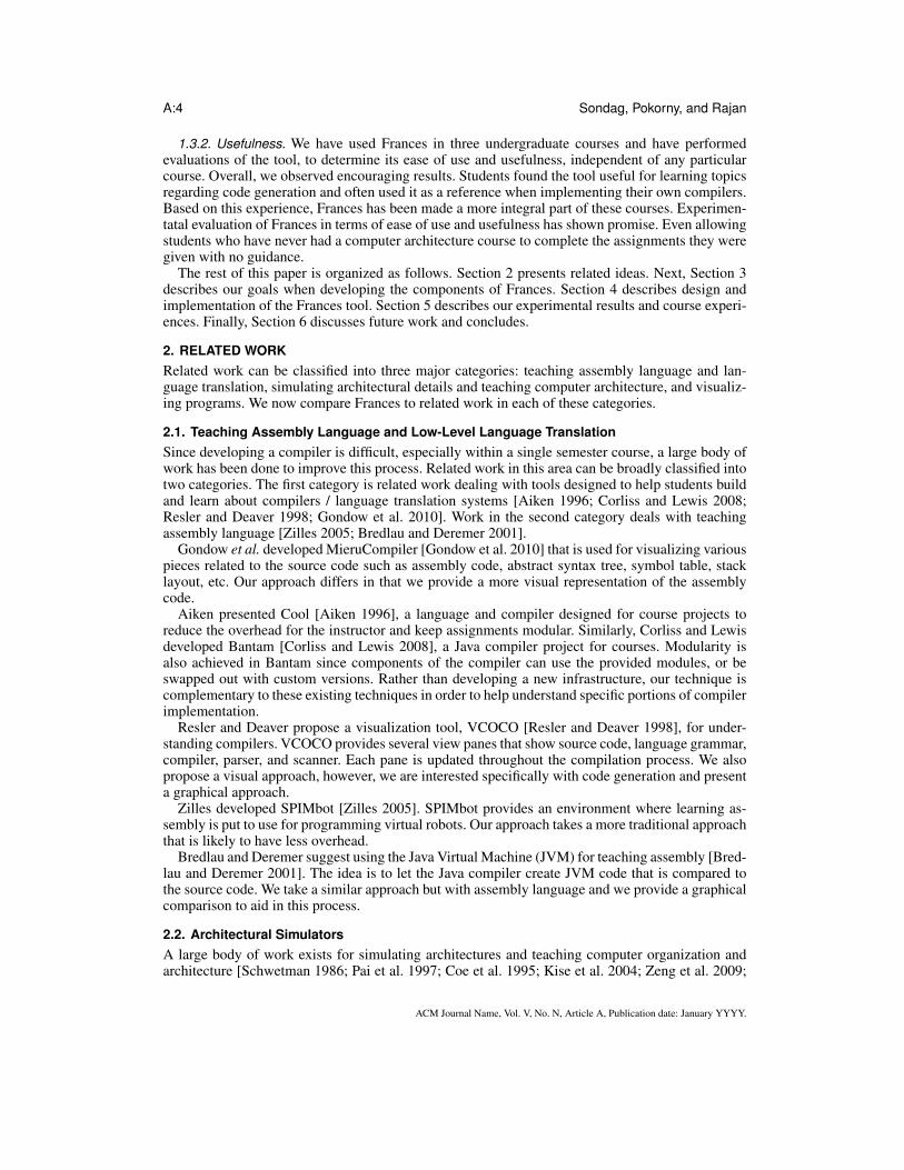
4.2.1. Backend. Key to implementing this part of the tool is a binary analysis and instrumenta-tion framework built for the SAPHA project [Sondag and Rajan 2011; 2010]. A diagram of thisframework is shown in Figure 6.
Fig. 6. Low-Level Component Architecture
Currently, this part of the tool allows users to input their own high-level language code in avariety of languages. This code is then translated by a compiler (e.g. gcc) to an object file as shownin Figure 6. Thus we are not tied to any language or compiler. Other high-level languages are alsoimmediately supported by simply installing a compiler on the server. For example, FORTRANsupport was added by simply sending the user’s source code through a FORTRAN compiler insteadof a C/C++ compiler.
Next, we make use of the GNU BinUtils [Free Software Foundation 2009] libraries to help con-vert these object files back into assembly code. The BinUtils library supports a variety of targetarchitectures and thus makes our tool very general in terms of target architecture and high-levellanguages. For example, we designed the system for the AT&T x86 syntax but have added supportfor Intel x86 syntax by simply changing minor settings and have added MIPS support by simplybuilding a cross-compiler on our server.
Our analysis tool then converts the assembly code into a format more suitable for analysis (C++objects). Since the binary contains virtual addresses for calls and jump targets, we convert these intolabels, which are easier to read. After address translation, we can construct the control flow graph(CFG) of the program.
The next step is done using our analysis and instrumentation framework, which consists of avariety of static analysis techniques. For this step, we use our implementations of standard controlflow analysis algorithms [Allen 1970; Muchnick 1997]. Through this process, the CFG is convertedto a graphical format where blocks of code are nodes in a graph. These nodes are arranged in thesame order as the assembly code to demonstrate how instruction ordering of low-level code worksand how it differs from high-level code. To further illustrate this topic, graph nodes (blocks ofinstructions) are colored to illustrate the purpose of the code (loop condition vs loop body, etc).This approach also handles nesting of control structures. Additionally, edges are drawn to illustratepotential program paths. These edges are drawn differently to illustrate the type of path (conditionaljump, unconditional jump, or no jump / fall-through). The results of this step are output as a “dot”file that is sent to the GraphViz dot [Ellson et al. 2001] program, which generates the graphicalrepresentation for the interface.
ACM Journal Name, Vol. V, No. N, Article A, Publication date: January YYYY.
A:12 Sondag, Pokorny, and Rajan
The source code of this framework is not yet publicly available, but will be released as an opensource project in the future. Until then, the tool is made available as a web service.
4.2.2. Graphical Representation and Interface. This component of the tool generates a simplegraphical representation of the target code corresponding to the source code. For example, in Fig-ure 5, this simple while loop is shown graphically as four blocks of code. Furthermore, the edges orpaths between these blocks that can be taken at run-time are shown. To generate the graphical pro-gram representation, we make use of dot, which is part of the GraphViz [Ellson et al. 2001] graphvisualization software. We now describe the major components of the representation including howblocks and edges are drawn as well as a brief discussion about the interface.
4.2.3. Blocks. Basic blocks of instructions are generated. A basic block is a sequence of instruc-tions with a single entry point and single exit point with no jumps between [Allen 1970]. For simplecontrol structures (non-nested structures) basic blocks capture the main components of the struc-tures. For example, in Figure 5, the sample while loop can be divided into two parts each witha different purpose: the loop body, and the loop condition. Therefore, the graphical version of thetarget code illustrates these two components of the loop in two separate blocks. Additionally, theblocks before and after the loop are also shown separately.
A major difference between previous tools and our tool is the way we lay out blocks. Similartools [The Informatik Centrum Dortmund (ICD) ; Titzer et al. 2005; AbsInt ] represent blocks asa flow chart. Since our major goal was to help students understand code generation, we make thisgraphical representation as close as possible to real generated code. We do this by maintaining theinstruction ordering of the actual target code. This includes the ordering of the blocks. To make thisordering clear, we represent blocks in a linear fashion in the same way that programs are representedin target code.
For example, in Figure 5, the layout of blocks is not done in a way that is immediately obviousfrom the source code. Consider the loop condition. In the source code, this is before the loop bodywhereas in the target code, it is after the loop body. This is not immediately clear to introductorystudents; however, for very good reasons this is how target code is generated by the compiler. Thus,understanding this ordering is necessary for understanding code generation. Therefore, our toolexposes students to such orderings. Given that this ordering is confusing, we take steps to helpclarify this ordering.
4.2.4. Color Coding. Since students are already familiar with a high-level language, we aim toquickly and clearly illustrate how control structures in a high-level language are represented in thetarget language. We show this by coloring the graph to highlight the different parts of the variouscontrol structures. Our tool performs simple control flow analyses [Muchnick 1997] on the code todetermine the different parts of the control structures. Then, the tool colors blocks based on the partof the control structure they make up (loop condition, loop body, etc). For example, in Figure 5 awhile loop is shown in both forms. Both the loop condition and the loop body are colored differentlyto make it easy to distinguish between the two. As mentioned previously, the ordering of these twoblocks is confusing at first since it differs from the source code ordering. This coloring, as delineatedin the Legend, quickly points out this ordering by showing that for this high-level language whileloop, the loop condition goes after the loop body.
For simple control structures, that is, non-nested control structures, we shade the background ofthe blocks to corresponding colors for each part of control structures. This includes structures suchas loops (loop body and loop condition are colored differently), if/else blocks, etc. As discussedpreviously, Figure 5 shows this for a simple while loop.
For nested control structures, the coloring must be done differently. We start by shading the blocksin the innermost structures as described previously. Then, all other structures are surrounded withboxes. These boxes are then shaded to show what kind of structure the member blocks are a part.Furthermore, this helps to show how the different structures interact. For example, consider thenested loop in Figure 7. The inner loop is composed of two blocks, the loop condition and the loop
ACM Journal Name, Vol. V, No. N, Article A, Publication date: January YYYY.
Frances: A Tool For Understanding Computer Architecture and Assembly Language A:13
body. These two blocks are shaded in the figure. We can see that both of these blocks (the entireinner loop) are contained within another structure since they are contained in a larger shaded box.This structure is the loop body of the outer loop, which is shown clearly by the shading.
Fig. 7. A simple nested while loop
This drawing of blocks shows how target code is laid out. Then the coloring helps to quicklyshow how components in familiar high-level code are represented in the target code. Furthermore,by breaking this representation down, we can focus on a smaller subset of the code.
4.2.5. Paths. The edges between blocks represent the paths that can be taken at run-time. A jumpin the target code can have up to two possible next instructions. The paths show these possible nextinstructions. For example, in Figure 5, we see that the loop condition (shown in green) has twooutgoing paths: one edge leading to the loop body (if the condition is true – conditional jump) andone edge leading to the next block after the loop that exits the loop (if the condition is false – nojump / fall-through).
In combination with blocks, edges help the user see how different structures are represented. Forexample, consider the first block in Figure 5. This figure illustrates how, in the target code, executionfirst jumps past the loop body to the loop condition (using an unconditional jump) for this type ofloop. This illustrates a key difference between while and do-while loops since do-while loops arenot organized this way.
As mentioned previously, the instruction (and block) ordering in the target code can be confusingto students because it is frequently different from the source code ordering. Our graphical represen-tation of blocks helps by highlighting the components of the different control structures. Illustratingthe ordering of control structures is helpful; however, we still need to show execution flows between
ACM Journal Name, Vol. V, No. N, Article A, Publication date: January YYYY.
A:14 Sondag, Pokorny, and Rajan
these structures. Figure 7 shows an example of a nested loop where paths help to illustrate the ini-tially confusing code layout. In this figure, we see that the edge corresponding to entering the innerloop actually goes to the second block in the inner loop. This is slightly confusing at first since thepath does not go to the beginning of the inner loop code. This example shows that it is important tounderstand how execution enters and exits loops. Furthermore, understanding how execution flowsthrough others structures such as if /else blocks is also important. Thus, we take steps to helpcontrast the differences between edges.
4.2.6. Edge Types. There are multiple types of edges. We illustrate the different types by usingdifferent styles of lines and arrowheads for drawing the edges. For example, in Figure 5, we see allthree different types of edges. We now give a brief description of each edge type.
— First, we have “unconditional jumps”. In the figure, this jump is illustrated with a dashedline and an empty triangular arrowhead. In Figure 5, the first block ends with the instructionjmp newLabel3. With this type of jump, the path is taken whenever the instruction is exe-cuted.
— Next, we have “no jump" (or “fall through” / “branch not taken”) edges. This edge type isillustrated with a thin edge and a “wedge shaped” arrowhead. This edge type goes to the nextsequential instruction when either the current instruction is not a jump or a condition is false. Forexample, the edge going from the loop body to the loop condition in the figure. In this case, sincethe block does not end with a jump, the next instruction is just the next sequential block. Anotherexample of this type of edge is the edge from the loop condition to the last block in Figure 5. Thisedge is taken when the condition on the jump, in this case $0x9 >= -0x8(%ebp), is false.This may seem trivial since the “no jump” edge is always the edge to the next sequential block,however, for students, this concept may not be immediately obvious.
— Finally, we have “conditional jump” (or “branch taken”) edges. These edges are drawn witha thick solid line and a solid triangular arrowhead. These edges are those that are taken whena jump condition is true. For example, in Figure 5, we have an edge from the loop conditionblock to the loop body block. This edge is taken whenever the loop condition on the loop is true.Another example is shown in Figure 8. In this example we can see a branch taken edge fromthe if condition block to the else body block. This edge is taken whenever the condition is true,however, in the source version, we have that this edge is taken whenever the if condition is false.This is another interesting difference between source and target code, which is nicely illustratedby this part of the tool.
This edge drawing helps illustrate the finer details of the target code. This includes how individualinstructions such as jumps are created and how complex control structure components such as nestedloops, interact . Together with our block drawing and coloring, this component of the tool generatesinformative and easy to understand figures, which illustrate how code generation is performed.
4.2.7. Benefits of Relating High-level to Machine Language in Frances. The block layout andcoloring in combination with the edge drawing greatly helps to teach the instruction layout of low-level language code. Furthermore, when viewed alongside familiar source code, this representationmakes the process of understanding translating between the two languages significantly easier. Withits simple and easy to use interface, Frances is easy to use in a course, will help students understandthese difficult concepts, and save valuable course time for other topics.
4.3. Graphical Layout of Machine StateWe now discuss in detail each aspect of the graphical representation of the machine state.
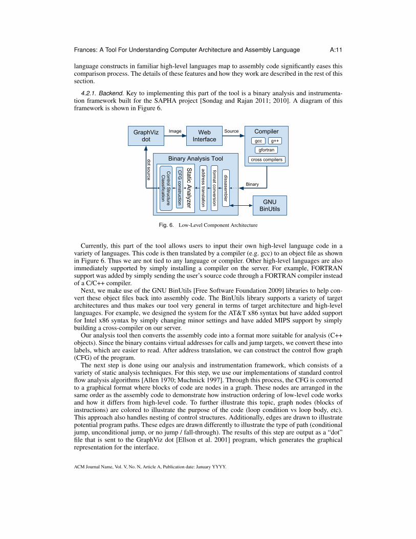
4.3.1. Previous / next instruction. The first part of the interface consists of the blocks marked“Last Instruction” and “Next Instruction”. As the labels suggest, these denote the previously exe-cuted instruction that gave the current state and the next instruction to be executed. For example, inFigure 9, a mov instruction was just executed and push %ecx is next.
ACM Journal Name, Vol. V, No. N, Article A, Publication date: January YYYY.
Frances: A Tool For Understanding Computer Architecture and Assembly Language A:15
Fig. 8. if-else block
This allows the user to find the current location in program execution. Then, they can considerthe changes caused by the last instruction. For example, in Figure 9 the user can see that in thelast instruction the value in %esp should have been placed into %ebp. By inspecting the currentstate, the user can see that these two registers currently contain the same value. Next, they can try todetermine the effects of the next instruction before it executes. For example, the user could predictthat the stack will grow by a location that will contain the value in %ecx.
It is interesting to note that the “Next Instruction” box contains the actual next instruction, notjust the next sequential instruction. That is, if the “Last Instruction” was a conditional jump and thebranch is set to be taken, the “Next Instruction” is the target of the branch not the fall-through case.
4.3.2. Registers. Next, the system’s registers are separated from the rest of the state. Within thisgroup of registers there are logical separations. In Figure 10, notice that the first row of registers arethe general purpose registers %eax, %ebx, %ecx, and %edx (even though all of the registers aregeneral purpose, many are typically used for specific purposes). In the next row, the two registers%esi and %edi are placed together since these are typically used for storing addresses for memoryreads and writes (again, the programmer need not follow this). Also in this row is the eflagsregister, which contains the results of compare instructions as well as other secondary results ofoperations. In this figure, we can see that the PF, SF, and IF flags are set (all others are unset).The interested user is presented the actual hex value of this register. In the final row, there arethree pointer registers. The first two are stack pointers, %esp and %ebp. By looking at the valuescontained in the figure, one can determine that these addresses are located on the stack. The finalregister in this row is %eip, the instruction pointer.
4.3.3. Stack. Next, consider the representation of the stack. Figure 10 shows a stack containing 8elements. Each element has its own row with columns specifying the address of the stack location
ACM Journal Name, Vol. V, No. N, Article A, Publication date: January YYYY.
A:16 Sondag, Pokorny, and Rajan
Fig. 9. Architecture state portion from Figure 4.
and the contents at that location. The stack locations are important since they contain most localvariables (some never leave the registers) as well as other temporary values. For example, in Fig-ure 10, the last instruction moved the value 0 to the third stack location. This corresponds to theassignment of int x = 0; from the code in Figure 4. The addresses are included in the represen-tation so that users can see how contents of registers correspond to locations on the stack (e.g. stackpointers %esp and %ebp). In the figures, it is easy to inspect the contents of these stack pointerregisters and find the corresponding locations on the stack.
4.3.4. Edges. Now, let us consider the edges in the figures. First, in Figure 10 notice that thereare two edges, one for both of the pointers into the stack. It is easy to see where these two registerspoint to on the stack. If the user is stepping through the simulation step by step, it is easy to see thatthe %ebp register points to the location on the stack before the 4 locations are added by the sub$0x10,%esp instruction. From the figure it is clear that the %esp register points to the top of thestack. This helps illustrate the purposes of the %esp and %ebp registers.
Also interesting to note are the edges in Figure 11. In this figure, the last instruction executedmoved the value in %eax (address of x, &x) to the fourth location on the stack. As a result, thereis now an edge from the stack location containing this value to the stack location corresponding to
ACM Journal Name, Vol. V, No. N, Article A, Publication date: January YYYY.
Frances: A Tool For Understanding Computer Architecture and Assembly Language A:17
Fig. 10. Frances state running the same code example as Figure 4 after the seventh instruction (int x = 0;).
variable x (third location on the stack). This illustrates the behavior of pointers in the machine. Thisis an important yet difficult concept for introductory students.
4.3.5. Color coding. Until this point, we have ignored the color coding of the machine state repre-sentation in these figures. We now describe this aspect of Frances, which helps illustrate the purposesof the instructions and their impact on the machine state.
First, the green boxes are used to denote portions of the state that always change and are notreferenced directly (previous and next instructions as well as instruction pointers). The purpose ofseparating out these components is to make it clear for users not to spend too much time tryingto understand how these components are directly impacted by the instructions since they are onlyimplicitly impacted. Note that the flags are not included in this scheme since they are not updatedat each step.
ACM Journal Name, Vol. V, No. N, Article A, Publication date: January YYYY.
A:18 Sondag, Pokorny, and Rajan
Fig. 11. Frances state running the same code example as Figure 4 after the tenth instruction (int *y = &x;).
Next, the color coding of the boxes for registers are considered. Yellow boxes around the registercontents signify that the last instruction accessed these registers (either read or write). For example,in Figure 11, we can see that the %eax register has been read (also note that it was the first operandin the last instruction). Additionally, the %ebp register has been accessed when calculating the stacklocation for the target of the operation.
Red highlighting of the register contents means that the contents were changed by the last in-struction. Consider Figure 4 where the %ebp register has been modified to contain the value from%esp.
Similarly, we use red highlighting to show which stack contents have been modified. For example,in Figure 10, the value of 0 was assigned to the stack location corresponding to variable x. Thus, thecorresponding stack location is red. This avoids the need for the user to try to determine the offsetof the stack location manually.
ACM Journal Name, Vol. V, No. N, Article A, Publication date: January YYYY.
Frances: A Tool For Understanding Computer Architecture and Assembly Language A:19
Finally, consider the edge color coding. In Figure 11, notice that the two stack pointers are drawnin black whereas the pointer in the stack corresponding to variable y is drawn in red. Like the registerand stack coloring, edges in red indicate change. In this example, since there is a modification to thepointer, the edge is red.
4.4. Reverse steppingAnother important feature of Frances, which is rare among similar tools, is the ability to step back-wards through execution. We consider this a necessary feature that allows students to revisit com-plicated steps and groups of steps in the simulation. Note that reversing can also be simulated in atool by rerunning the simulation, however, students may lose the context of simulation if too manysteps are required for revisiting the previous instruction. With Frances a student can step back andforth to ascertain every detail of an instruction’s impact on the machine state.
We color code changes to the state in red, however, this may not be enough. Thus, we allowstudents to go back so that they can revisit the state before it was modified. For example, whenmoving stack pointers, in order to understand behavior and purpose of the different pointers, it maybe important to go back to see the previous target of the pointer register. Need for such a featuremay be seen from Figure 4. We can see that the %ebp register changed to point to the top of thestack. However, we know nothing about where it pointed to previously. By simply clicking the “LastInstruction” button, we can clearly see the previous target of the register.
4.5. BackendOn the backend, we make use of the GDB debugger [Free Software Foundation 2010] to stepthrough instructions individually and obtain the values in each register and stack location betweeneach instruction. Aside from this, we use several scripts and programs to visually present the stateas well as determine changes. After this, we use the GraphViz DOT program [Ellson et al. 2001]to draw the visualization of the machine code and machine state. Each visualization state’s imageis stored on the server until the user is done with the visualization (“reset” is clicked or a timeoutoccurs). Thus, to implement backwards stepping, we simply load the image associated with theprevious state. Similarly, when forward stepping to a state already generated, the server can simplyload the images for these states.
5. EVALUATIONIn this section we discuss the evaluation of the Frances tool. First, Frances is compared with othersimilar tools. Second, we provide a discussion of classroom experiences. Third we provide resultsfrom a small experimental study introducing Frances to groups of randomly selected students withvarious levels of computer architecture experience.
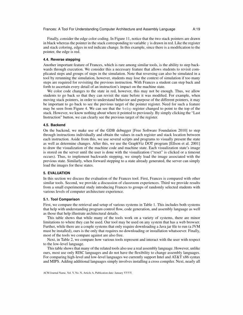
5.1. Tool ComparisonFirst, we compare the retrieval and setup of various systems in Table 1. This includes both systemsthat help with understanding program control flow, code generation, and assembly language as wellas those that help illustrate architectural details.
This table shows that while many of the tools work on a variety of systems, there are minorlimitations to where they can be used. Our tool may be used on any system that has a web browser.Further, while there are a couple systems that only require downloading a Java jar file to run (a JVMmust be installed), ours is the only that requires no downloading or installation whatsoever. Finally,most of the tools we compare against are also free.
Next, in Table 2, we compare how various tools represent and interact with the user with respectto the low-level language.
This table shows that many of the related tools also use a real assembly language. However, unlikeours, most use only RISC languages and do not have the flexibility to change assembly languages.For comparing high-level and low-level languages we currently support Intel and AT&T x86 syntaxand MIPS. Adding additional languages simply involves installing a cross compiler. Next, nearly all
ACM Journal Name, Vol. V, No. N, Article A, Publication date: January YYYY.
A:20 Sondag, Pokorny, and Rajan
Table 1. Comparison of Tool Setup
Tool OS Platform Req. Install FreeFrances Any No YesMarieSIM JVM Download Jar YesMieru Compiler Unix variants,Windows Build YesGSPIM Unknown Unknown UnknownSimpleScalar (ss-vis) Unix variants Yes AcademicSimple Computer Source Build YesGDB Unix variants,Windows Yes YesKDBG Linux Yes YesICD-C Linux,Solaris,Windows Yes NoAvora JVM Download Jar YesaiCall Linux,Mac,Windows Yes Academic3
Table 2. Comparison of Tool Assembly Representation. Irrelevant tools from Table 1 removed.
Tool Asm. Lang HLL ↔ASM
InstructionOrdering
CFGraph
Path Types Coloring
Frances Real Yes Actual Yes Intra-procedural YesMieru Compiler Real Text Actual (text) No N/A Current codeGSPIM Real (MIPS) No Not-actual Yes Calls vs. Jumps Current nodeICD-C N/A N/A Not-actual Yes Unknown YesAvora Real (AVR) N/A Not-actual Yes Calls vs. Jumps Entry pointsaiCall N/A N/A Not-actual Yes Yes Decision nodes,
Entry points,Edge types
the tools do not show how user entered high-level code corresponds to low-level code. Debuggersand debugger front-ends frequently show the version of the program side-by-side (users may alsodo this manually), but this is no more than a simple text comparison. Ours is the only tool we knowof that automatically shows how the two versions compare and breaks the complex assembly codeinto its control structures graphically. Similar to text-based representations, which are difficult tounderstand for beginners, our tool maintains actual instruction ordering in our graphical representa-tion of the machine code. While nearly all the tools in the table display a control flow graph, noneof these graph based tools maintain actual instruction order. Next, most of the tools also distinguishbetween path types, however, most only distinguish between inter- vs intra-procedural edges (some-times as separate graphs). Finally, most of the tools also use some sort of coloring to make readingthe control flow graphs easier. However, most are quite limited in what they differentiate between.For tools that illustrate execution, they often just highlight the current node. Others often just showprocedure entry points or decision nodes.
Now, in Table 3, we compare how various tools represent and interact with the user with respectto simulation and illustrating execution at the architecture level. Note that this is just a small subsetof the tools that are more suitable in undergraduate level education. We leave out many research andadvanced tools from this table (most of these are text/command line based).
Table 3. Comparison of Tool Machine Visualization. Irrelevant tools from Table 1 removed.
Tool SimulationLanguage
StepBack
GraphicalMachine
ColorMachine
EdgesMachine
EdgesColor
Frances HLLs, ASM Yes Yes Yes Yes YesMarieSIM ASM (Custom) No Yes No No NoGSPIM ASM (MIPS) No No N/A N/A N/ASimpleScalar (ss-vis) Pisa Binary No Yes Yes No N/ASimple Computer ASM (Custom) No No N/A N/A N/AGDB HLLs,ASM No No N/A N/A N/AKDBG HLLs,ASM No Yes Yes No N/A
ACM Journal Name, Vol. V, No. N, Article A, Publication date: January YYYY.
Frances: A Tool For Understanding Computer Architecture and Assembly Language A:21
First, among the tools, there is quite a mix of assembly languages including real languages (bothRISC and CISC) and custom languages. However, aside from the debuggers, ours is the only toolthat also shows a high-level language version of the program being run and allows users to entersimulation code in a high-level language. Additionally, our tool is the only tool we found that allowsusers to step backwards through execution. We believe this to be an important feature for revisitingcomplicated steps or sets of steps. Finally, several of the tools create graphical version of the ma-chine state like our tool. Some also even color code parts of the machine state (e.g. recently reador written values). However, ours is the only tool we found that illustrates pointers in the machinestate and colors the edges of these pointers to show recent changes.
Summary In summary, this comparison illustrates the key feature differences between Francesand related tools. We show that Frances is easier to start using than related tools (platform inde-pendent, doesn’t require install, and is free). Further, among related tools, Frances is the only toolthat graphically shows relationships between high-level and low-level languages while maintaininginstruction order. Finally, Frances is the only tool that allows students to step backwards to revisitcomplex steps/procedures and illustrates edges (pointers) in the machine state.
5.2. Classroom ExperiencesEducational materials have been developed for use in several courses. The materials associated withthe Frances tool have been successfully used in multiple sections of an upper level compiler con-struction course with a total of 20 students. The students enrolled in this course have had courses indata structures, computer architecture and operating systems. In the computer architecture coursetextbook [Stallings 2010], students were provided an introduction to instruction sets. However, thestudents have had no experience with assembly language programming. Frances was used in severalclass sessions to introduce assembly language. Then as various language constructs arose, Franceswas used to investigate the low-level implementation of these constructs. Students reported thatthey found the tool easy to use and scored an average of 93.8% on the seven lab assignments usingFrances to understand AT&T x86 assembly language. Furthermore, the students used the tool forreference in the development of a compiler created as part of the course. Students reported using thetool in an exploratory manner to gain insight into generating assembly code for the compiler con-structed as a course project. Subsequently the Frances tool and course materials have been integratedinto the compiler course curriculum at McKendree University.
Additionally, Frances and associated course materials have been introduced into a computer ar-chitecture course. The course materials, developed for integration into the course, allow the in-structor to continue using a standard textbook in the subject and interject the Frances materials forvarious topics. Initially it was used to introduce the concept of translating from a high-level to a low-level language. Then it was used as an example of a real system for topics such as variable types,operands, addressing modes, and registers. The Frances tool has also been introduced as an explana-tory tool in CS1 course offerings with promising results. During introductory discussions about thecompilation process students were able to get a sense of the translation process from high-level tolow-level language. Students gave positive comments in regards to understanding how instructionsare processed in the computer. As part of our future work we plan to incorporate high-level languageaspects into the Frances system in an effort to help facilitate further integration into CS1/CS2.
5.3. Empirical StudyOur classroom experiences with Frances indicated that the tool is useful for its intended purpose inproviding students with a connection between low-level and high-level language translation, allow-ing students to gain experience with assembly languages and an insight into computer architecturein an easy to understand integrated environment. In an effort to collect more data regarding the effec-tive usage of the Frances tool, an experimental design was developed. The goal of this initial studywas to collect data for ease of use; usefulness in regards to making a connection between high-Levellanguages and low-Level languages; in understanding machine states; and in introducing assemblylanguage. Twenty-nine students were randomly selected from undergraduates majoring in computer
ACM Journal Name, Vol. V, No. N, Article A, Publication date: January YYYY.
A:22 Sondag, Pokorny, and Rajan
science, computational science, and information systems. All of the students had completed a twocourse sequence in computer programming and some were currently enrolled in a data structurescourse. Since Frances focuses on making a connection between high-level and low-level languages,and computer architecture we stratified the group on computer architecture course experience. Somestudents had completed a course in computer architecture (DONE, N=4), some were currently en-rolled (IP, N=12) and some had no experience with the subject (NONE, N=13). This course is astandard course in computer architecture using the textbook by Stallings [Stallings 2010].
5.3.1. Experimental Setup. The goals of this study are to investigate if students can easily be-gin using the Frances tool and how effective the tool is in conveying its intended information. Asindicated from the classroom experience section of this paper, in the context of a course, studentseasily understood how to use the system and found it to be very useful component of the the course.Students using the system without the context of a course or instructor help provide a strongerindication of the tool’s effectiveness and ease of use.
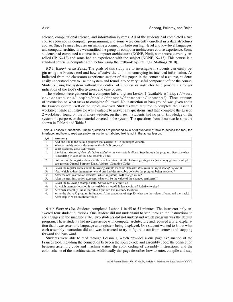
The students were gathered in a computer lab and given Lesson 1 (available at http://www.cs.iastate.edu/~sapha/tools/frances/frances-a/lessons/). Three minutesof instruction on what tasks to complete followed. No instruction or background was given aboutthe Frances system itself or the topics involved. Students were required to complete the Lesson 1worksheet while an instructor was available to answer any questions, and then complete the Lesson2 worksheet, found on the Frances website, on their own. Students had no prior knowledge of thesystem, its purpose, or the material covered in the system. The questions from these two lessons areshown in Table 4 and Table 5.
Table 4. Lesson 1 questions. These questions are preceded by a brief overview of how to access the tool, theinterface, and how to read assembly instructions. Italicized text is not in the actual lesson.
Q# Summary1 Add one line to the default program that assigns “5” to an integer variable.1a What assembly code is the same as the default program?1b What assembly code is different?1c A brief description of the code before and after the new code is elided. Step through the program. Describe what
is occurring in each of the new assembly lines.2 Put each of the register shown in the machine state into the following categories (some may go into multiple
categories): General Purpose, Data, Address, Condition Codes.3 Given the register values in the following sample machine state (the state from the right side of Figure 3).3a Near which address in memory would one find the assembly code for the program being executed?3b After the next instruction executes, which register(s) will change value?3c After the next instruction executes, what will be the value of the changed register(s)?4 Given the following example state. Shown here as Figure 12.4a At which memory location is the variable x stored? In hexadecimal? Relative to ebp?4b At which assembly line is the value 2 put into this memory location?4c Write the above C program in Frances. After execution of step 13, what are the values of eax and the stack?
After step 14 what are these values?
5.3.2. Ease of Use. Students completed Lesson 1 in 45 to 53 minutes. The instructor only an-swered four student questions. One student did not understand to step through the instructions tosee changes in the machine state. Two students did not understand which program was the defaultprogram. These students had no experience with computer architecture and required a brief explana-tion that it was assembly language and registers being displayed. One student wanted to know whateach assembly instruction did and was instructed to try to figure it out from context and steppingforward and backward.
Students were able to read through Lesson 1, which provides a one page explanation of theFrances tool, including the connection between the source code and assembly code; the connectionbetween assembly code and machine states; the color coding of assembly instructions; and thecolor scheme of the machine states. Additionally this page describes how to enter, compile and step
ACM Journal Name, Vol. V, No. N, Article A, Publication date: January YYYY.
Frances: A Tool For Understanding Computer Architecture and Assembly Language A:23
Fig. 12. Lesson 1 question 4 example.
Table 5. Lesson 2 questions. Italicized text is not in the actual lesson.
Q# Summary1 Go to the Frances-A site and type the following code into Frances-A. Sample program shown with main only
containing the statements: int n=5; char c=’5’; float y=5;1a Write the assembly code that stores 5 into n.1b Write the assembly code that stores ’5’ into c.1c Write the assembly code that stores 5 into y.1c.i Why do you think the float is stored differently than the int and char?1c.ii This is stored in the IEEE 754 standard. Convert it from this representation to its decimal value. Show all work.2 Step through the program.2a How many bytes does the integer occupy?2a.i What is the address of and value stored in the memory location.2b How many bytes does the char occupy?2b.i What is the address of and value stored in the memory location.2b.ii What was stored in this address prior to execution of the instruction storing the char?2c How many bytes does the float occupy?2c.i What is the address of and value stored in the memory location.3 What are the mov, movb, and movl instructions? Why are they different?4 What is the purpose of the sub and add instructions that occur before and after these mov instructions?5 Replace the line char c; with the line char c[5] = {’1’, ’2’, ’3’, ’4’, ’5’};5a Step through the program.5b How is this array stored? Write the addresses and value in the memory locations prior to moving any data and
then after each mov associated with the array
ACM Journal Name, Vol. V, No. N, Article A, Publication date: January YYYY.
A:24 Sondag, Pokorny, and Rajan
through programs; a description of the assembly language format; and a description of registers,addresses, and value prefixes in the assembly instructions. These explanations are very brief, fittingon a single page.
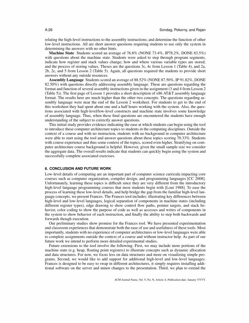
Students then went on to use the Frances system completing the lessons and answering 25 ques-tions pertaining to assembly language, computer architecture concepts, and machine states with anoverall mean score of 91.25 out of 125. This equates to 75.70%. Thus, in general, students wereeasily able to use the system with little instruction or context and successfully demonstrate an un-derstanding of the material. Stratifying these results across prior computer architecture course ex-perience reveals more information. Students with no current or previous enrollment in a computerarchitecture course (NONE) had a mean score 70.30%, students currently enrolled in a computerarchitecture course (IP) had a mean score of 79.64%, and students who have completed a com-puter architecture course (DONE) had a mean score of 81.00%. Boxplots of this data are shown inFigure 13.
NONEIPDONE
100
80
60
40
20
0
Comp. Arch. Course
Sco
re
Fig. 13. Overall scores for lessons. DONE: Completed computer architecture course. IP: Currently enrolled in a computerarchitecture course. NONE: Not completed or enrolled in a computer architecture course.
When surveyed on a scale of 1-5 (1 being very difficult, 3 neutral and 5 very easy) students ratedease of use with a mean of 3.59 overall. Again, stratifying on computer architecture course expe-rience NONE rated ease of use at 3.62, IP at 3.33 and DONE at 4.25. Box plots of this data arepresented in Figure 14. This may indicate that the opinion of the ease of use is tied to an under-standing of the material covered. Students with less context of the experience felt that the systemwas not as easy to use as those that had a completed a course covering the topics. However, moredata would need to be gathered from students that have completed a computer architecture course(i.e., DONE).
In summary, students with no experience in the topics covered in these lessons were able to learnthe tool on their own, with little to no instructor help, and complete the lessons which demonstratesthat the tool is easy to learn to use.
5.3.3. Usefulness. In this subsection, we consider the usefulness of the tool. Table 6 providesthe mean and standard deviation of the student responses to the lesson questions. The first threecolumns show the results for the respective computer architecture experience and the last column
ACM Journal Name, Vol. V, No. N, Article A, Publication date: January YYYY.
Frances: A Tool For Understanding Computer Architecture and Assembly Language A:25
NONEIPDONE
5
4
3
2
1
Comp. Arch. Course
Ho
w e
asy w
as i
t to
sta
rt u
sin
g?
Fig. 14. Survey results on the opinion of ease of use.
provides the aggregate results for all students. The first row gives the results for all questions andthe last three rows give the results for high-level/low-level, machine state, and assembly languageconcepts, respectively. Overall students were very successful with the system. As shown in the
Table 6. Scores for lessons 1 and 2 (%)
NONE IP DONE ALLMean St.Dev. Mean St.Dev. Mean St.Dev. Mean St.Dev.
first row of Table 6, the average score is 75.70%. Separating students by experience reveals more.Students with no background in computer architecture scored, on average, 70.33%. This indicatesthat in less than two hours, students without experience in the subject or proper context of the systemwere able to learn the system, use it and answer the questions with a 70.33% score. Students withexperience in computer architecture scored 79.64% and 81.00% for IP and DONE, respectively.These students have experience with a traditional course in computer architecture, but no exposureto a real assembly language or architecture. Again they were able to successfully understand thesystem and material outside the context of a course, in less than two hours.
Next we break the data down into components to investigate the effectiveness of the system foraiding in the understanding of the connection between high-level and low-level Language, machinestate constructs, and Assembly Language.
High-level and Low-level Language Relationships Students scored an average of 76.00%(NONE 74.20%, IP 69.50%, DONE 84.00%) with questions regarding the connection between high-level and low-level languages. The questions used for this assessment are 1c and 4a from Lesson 1(Table 4), as well as 1a–c from Lesson 2 (Table 5). None of the students had previous experiencewith a real assembly language. The questions asked students to write a high-level language program,step through the resulting assembly language program segment and describe the result of each as-sembly instruction, relating it to the high-level code; identify the storage location of a variable by
ACM Journal Name, Vol. V, No. N, Article A, Publication date: January YYYY.
A:26 Sondag, Pokorny, and Rajan
relating the high-level instructions to the assembly instructions; and determine the function of otherlow-level instructions. All are short answer questions requiring students to use only the system indetermining the answers with no other hints.
Machine State Students scored an average of 76.8% (NONE 73.4%, IP78.2%, DONE 83.5%)with questions about the machine state. Students were asked to step through program segments,indicate how register and stack values change; how and where various variable types are stored;and the process of storing values. Theses are the questions 3c, 4c from Lesson 1 (Table 4), and 2a,2b, 2c, and 5 from Lesson 2 (Table 5). Again, all questions required the students to provide shortanswers without any outside resources.
Assembly Language Students scored an average of 88.52% (NONE 87.50%, IP 91.82%, DONE82.50%) with questions directly addressing assembly language. These are questions regarding theformat and function of several assembly instructions given in the assignment (3 and 4 from Lesson 2(Table 5)). The first page of Lesson 1 provides a short description of x86 AT&T assembly languageformat. The results here are much higher than the other two concepts. The questions regarding as-sembly language were near the end of the Lesson 2 worksheet. For students to get to the end ofthis worksheet they had spent about one and a half hours working with the system. Also, the ques-tions associated with high-level/low-level constructs and machine state involves some knowledgeof assembly language. Thus, when these final questions are encountered the students have enoughunderstanding of the subject to correctly answer questions.
This initial study provides evidence indicating the ease at which students can begin using the toolto introduce these computer architecture topics to students in the computing disciplines. Outside thecontext of a course and with no instruction, students with no background in computer architecturewere able to start using the tool and answer questions about these topics scoring 70.33%. Studentswith course experience and thus some context of the topics, scored even higher. Stratifying on com-puter architecture course background is helpful. However, given the small sample size we considerthe aggregate data. The overall results indicate that students can quickly begin using the system andsuccessfully complete associated exercises.
6. CONCLUSION AND FUTURE WORKLow-level details of computing are an important part of computer science curricula impacting corecourses such as computer organization, compiler design, and programming languages [CC 2008].Unfortunately, learning these topics is difficult since they are very different from the introductoryhigh-level language programming courses that most students begin with [Loui 1988]. To ease theprocess of learning these low-level details, and help bridge the gap from the familiar high-level lan-guage concepts, we present Frances. The Frances tool includes: illustrating key differences betweenhigh-level and low-level languages, logical separation of components in machine states (includingdifferent register types), edge drawing to show control flow paths, pointer targets, and stack be-havior, color coding to show the purpose of code as well as accesses and writes of components inthe system to show behavior of each instruction, and finally the ability to step both backwards andforwards though execution.
Our preliminary studies show promise for the Frances tool. We have presented experimentationand classroom experiences that demonstrate both the ease of use and usefulness of these tools. Mostimportantly, students with no experience of computer architectures or low-level languages were ableto complete assignments outside the context of a course and without instructor help. As part of ourfuture work we intend to perform more detailed experimental studies.
Future extensions to the tool involve the following. First, we may include more portions of themachine state (e.g. heap, floating point registers) to illustrate concepts such as dynamic allocationand data structures. For now, we focus less on data structures and more on visualizing simple pro-grams. Second, we would like to add support for additional high-level and low-level languages.Frances is designed to be easy to swap in different architectures, it simply requires installing addi-tional software on the server and minor changes to the presentation. Third, we plan to extend the
ACM Journal Name, Vol. V, No. N, Article A, Publication date: January YYYY.
Frances: A Tool For Understanding Computer Architecture and Assembly Language A:27
tool to handle tracking values of high-level variables. Finally, we plan to continue evaluating andimproving the tool based on both student and expert evaluations.
ACKNOWLEDGMENTS
The authors would like to thank the students who tested the tool as well as the anonymous reviewers for their commentsand suggestions. Sondag and Rajan were supported in part by US NSF under grants 06-27354, 07-09217, 08-46059, and11-17936.
REFERENCESABSINT. aiSee - Graph Visualization. http://www.absint.com/aisee/.AIKEN, A. 1996. Cool: a portable project for teaching compiler construction. SIGPLAN Not. 31, 7, 19–24.ALLEN, F. E. 1970. Control flow analysis. In Symposium on Compiler optimization. 1–19.BINKERT, N. L., HALLNOR, E. G., AND REINHARDT, S. K. 2003. Network-oriented full-system simulation using M5. In
Workshop on Computer Architecture Evaluation using Commercial Workloads.BORUNDA, P., BREWER, C., AND ERTEN, C. 2006. GSPIM: graphical visualization tool for MIPS assembly programming
and simulation. SIGCSE Bull. 38, 1, 244–248.BRAUGHT, G. AND REED, D. 2001. The knob & switch computer: A computer architecture simulator for introductory
computer science. J. Educ. Resour. Comput. 1, 4, 31–45.BREDLAU, C. AND DEREMER, D. 2001. Assembly language through the Java virtual machine. In SIGCSE ’01: Proceedings
of the 32nd ACM technical symposium on Computer science education.CC. 2008. Computing curricula 2008: An interim revision of cs 2001. CC. http://www.acm.org/education/curricula/ Com-
puterScience2008.pdf.COE, P. S., HOWELL, F. W., IBBETT, R. N., MCNAB, R., AND WILLIAMS, L. M. 1995. An integrated learning support
environment for computer architecture. In WCAE-3 ’97: Proceedings of the 1997 workshop on Computer architectureeducation. ACM, New York, NY, USA, 8.
CONWAY, M. J. AND PAUSCH, R. 1997. Alice: easy to learn interactive 3d graphics. SIGGRAPH Comput. Graph. 31, 3,58–59.
CORLISS, M. L. AND LEWIS, E. C. 2008. Bantam: a customizable, Java-based, classroom compiler. In SIGCSE ’08: Pro-ceedings of the 39th ACM technical symposium on Computer science education.
ELLSON, J., GANSNER, E. R., KOUTSOFIOS, E., NORTH, S. C., AND WOODHULL, G. 2001. Graphviz - open sourcegraph drawing tools. Graph Drawing, 483–484.
ESPONDA-ARGUERO, M. 2008. Algorithmic animation in education—review of academic experience. Journal of Educa-tional Computing Research 39, 1–15.
FREE SOFTWARE FOUNDATION. 2009. GNU BinUtils: a collection of binary tools. http://www.gnu.org/software/binutils/.FREE SOFTWARE FOUNDATION. 2010. GDB: The GNU Project Debugger. http://www.gnu.org/software/gdb/.GONDOW, K., FUKUYASU, N., AND ARAHORI, Y. 2010. Mierucompiler: integrated visualization tool with "horizontal
slicing" for educational compilers. In SIGCSE ’10: Proceedings of the 41st ACM technical symposium on Computerscience education. ACM, New York, NY, USA, 7–11.
GRAHAM, N. 1985. Introduction to computer science (3rd ed.). West Publishing Co., St. Paul, MN, USA.HUNDHAUSEN, C. D. 2002. Integrating algorithm visualization technology into an undergraduate algorithms course: ethno-
graphic studies of a social constructivist approach. Comput. Educ. 39, 3, 237–260.KISE, K., KATAGIRI, T., HONDA, H., AND YUBA, T. 2004. The simcore/alpha functional simulator. In WCAE ’04: Pro-
ceedings of the 2004 workshop on Computer architecture education. ACM, New York, NY, USA, 24.LOUI, M. C. 1988. The case for assembly language programming. IEEE Transactions on Education E-31, 3, 160–164.LUK, C.-K., COHN, R., MUTH, R., PATIL, H., KLAUSER, A., LOWNEY, G., WALLACE, S., REDDI, V. J., AND HAZEL-
WOOD, K. 2005. Pin: building customized program analysis tools with dynamic instrumentation. In PLDI ’05: Pro-ceedings of the conference on Programming language design and implementation. 190–200.
MCNALLY, M., NAPS, T. L., FURCY, D., GRISSOM, S., AND TREFFTZ, C. 2007. Supporting the rapid development ofpedagogically effective algorithm visualizations. Journal of Computing Sciences in Colleges 23, 1 (10/2007), 80–90.
MUCHNICK, S. S. 1997. Advanced compiler design and implementation. Morgan Kaufmann Publishers Inc., San Francisco,CA, USA.
NAPS, T. L., RÖSSLING, G., ALMSTRUM, V., DANN, W., FLEISCHER, R., HUNDHAUSEN, C., KORHONEN, A., MALMI,L., MCNALLY, M., RODGER, S., AND VELÁZQUEZ-ITURBIDE, J. A. 2002. Exploring the role of visualization andengagement in computer science education. In ITiCSE-WGR ’02: Working group reports from ITiCSE on Innovationand technology in computer science education. ACM, New York, NY, USA, 131–152.
ACM Journal Name, Vol. V, No. N, Article A, Publication date: January YYYY.
A:28 Sondag, Pokorny, and Rajan
NIKOLIC, B., RADIVOJEVIC, Z., DJORDJEVIC, J., AND MILUTINOVIC, V. 2009. A survey and evaluation of simulatorssuitable for teaching courses in computer architecture and organization. IEEE Transactions on Education 52, 449 – 458.
NULL, L. AND LOBUR, J. 2003. MarieSim: The MARIE computer simulator. J. Educ. Resour. Comput. 3, 2, 1.PAI, V. S., RANGANATHAN, P., AND ADVE, S. V. 1997. RSIM: Rice simulator for ILP multiprocessors. SIGARCH Comput.
Archit. News 25, 5, 1.PATT, Y. N. AND PATEL, S. J. 2004. Introduction to Computing Systems: From Bits & Gates to C & Beyond, 2 ed. McGraw-
Hill, Inc., New York, NY, USA.PAUW, W. D., JENSEN, E., MITCHELL, N., SEVITSKY, G., VLISSIDES, J. M., AND YANG, J. 2002. Visualizing the
execution of Java programs. In Revised Lectures on Software Visualization, International Seminar. Springer-Verlag,London, UK, 151–162.
POWERS, K., GROSS, P., COOPER, S., MCNALLY, M., GOLDMAN, K. J., PROULX, V., AND CARLISLE, M. 2006. Toolsfor teaching introductory programming: what works? SIGCSE Bull. 38, 1, 560–561.
PRICE, B. A., SMALL, I. S., AND BAECKER, R. M. 1992. A taxonomy of software visualization. Journal of Visual Lan-guages and Computing 4, 211–266.
REISS, S. P. 2003. Visualizing Java in action. In SoftVis ’03: Proceedings of the 2003 ACM symposium on Software visual-ization. ACM, New York, NY, USA, 57–ff.
RESLER, R. D. AND DEAVER, D. M. 1998. Vcoco: a visualisation tool for teaching compilers. SIGCSE Bull. 30, 3, 199–202.
RÖSSLING, G. AND VELÁZQUEZ-ITURBIDE, J. Á. 2009. Editorial: Program and algorithm visualization in education.Trans. Comput. Educ. 9, 2, 1–6.
SANDERS, D. AND DORN, B. 2003. Jeroo: a tool for introducing object-oriented programming. In SIGCSE ’03: Proceedingsof the 34th SIGCSE technical symposium on Computer science education. ACM, New York, NY, USA, 201–204.
SCHWETMAN, H. 1986. Csim: a c-based process-oriented simulation language. In Conference on Winter simulation. ACM,New York, NY, USA, 387–396.
SHERWOOD, T., PERELMAN, E., HAMERLY, G., AND CALDER, B. 2002. Automatically characterizing large scale programbehavior. In ASPLOS-X: Proceedings of the 10th international conference on Architectural support for programminglanguages and operating systems. ACM, New York, NY, USA, 45–57.
SIXT, J. 2010. A graphical debugger interface. http://www.kdbg.org/.SONDAG, T. AND RAJAN, H. 2010. A more precise abstract domain for multi-level caches for tighter wcet analysis. In
Proceedings of the 2010 31st IEEE Real-Time Systems Symposium.SONDAG, T. AND RAJAN, H. 2011. Phase-based tuning for better utilization of performance-asymmetric multicore proces-
sors. In CGO: Proceedings of the 9th annual IEEE/ACM International Symposium on Code Generation and Optimiza-tion.
STALLINGS, W. 2010. Computer Organization and Architecture: Designing fro Performance (8th ed.). Pearson EducationInc., Upper Saddle River, New Jersy, USA.
STONE, J. A. 2006. Using a machine language simulator to teach CS1 concepts. SIGCSE Bull. 38, 4, 43–45.SUNDARARAMAN, J. AND BACK, G. 2008. HDPV: interactive, faithful, in-vivo runtime state visualization for C/C++ and
Java. In SoftVis ’08: Proceedings of the 4th ACM symposium on Software visualization. ACM, New York, NY, USA,47–56.
THE INFORMATIK CENTRUM DORTMUND (ICD). ICD-C Compiler Framework. http://www.icd.de/es/icd-c/.TITZER, B., LEE, D., AND PALSBERG, J. 2005. Avrora: Scalable sensor network simulation with precise timing. In Infor-
mation Processing in Sensor Networks (IPSN).URQUIZA-FUENTES, J. AND VELÁZQUEZ-ITURBIDE, J. Á. 2009. A survey of successful evaluations of program visual-
ization and algorithm animation systems. Trans. Comput. Educ. 9, 2 (06/2009), 1–21.WOLZ, U., MALONEY, J., AND PULIMOOD, S. M. 2008. ’scratch’ your way to introductory cs. In SIGCSE ’08: Proceedings
of the 39th SIGCSE technical symposium on Computer science education. ACM, New York, NY, USA, 298–299.ZENG, H., YOURST, M., GHOSE, K., AND PONOMAREV, D. 2009. MPTLsim: a cycle-accurate, full-system simulator for
x86-64 multicore architectures with coherent caches. SIGARCH Comput. Archit. News 37, 2, 2–9.ZILLES, C. 2005. Spimbot: an engaging, problem-based approach to teaching assembly language programming. SIGCSE
Bull. 37, 106–110.
Received R; revised e; accepted ceived Month Year; Month Year; accepted Month Year
ACM Journal Name, Vol. V, No. N, Article A, Publication date: January YYYY.