+ All Categories
Home > Documents > A fully coupled thermomechanical 3D model for all phases ...

A fully coupled thermomechanical 3D model for all phases ...

Date post: 23-Dec-2021
Category:
Upload: others
View: 4 times
Download: 0 times
Share this document with a friend
11
A fully coupled thermomechanical 3D model for all phases of friction stir welding M. Hossfeld Rapid Technic AG, Killwangen, Switzerland E-mail: [email protected] April 2016 Abstract. Although friction stir welding (FSW) has made its way to industrial application particularly in the last years, the FSW process, its influences and their strong interactions among themselves are still not thoroughly understood. The lack of understanding mainly arises from the adverse observability of the actual process with phenomena like material flow and deposition, large material deformations plus their complex thermo-mechanical interactions determining the weld formation and its mechanical properties. A validated numerical process model may be helpful for closing this gap as well as for an isolated assessment of individual influences and phenomena. Hereby such a model will be a valuable assistance for process and especially tool development. In this study a Coupled Eulerian-Lagrangian (CEL) approach with Abaqus V6.14 is used for modeling the whole FSW process within one continuous model. The resolution reached allows not only simulating the joining of two sheets into one and real tooling geometries but also burr and internal void formation. Results for temperature fields, surface and weld formation as well as process forces are shown and validated. 1. Introduction Object of the present work is to simulate all stages of the FSW process within one continuous FE model. Therefore a fully coupled thermomechanical 3D model has been developed using the CEL-algorithm of Noh and Abaqus V6.14 [1, 2]. In previous work [3, 4] we found out that this combination was able to deal with the big challenges of modeling FSW that derive from the working principle with non-linear phenomena like material flow, friction and other complex interactions. Furthermore, the simulation of joining two separate sheets into one was possible as well as a detailed prediction of resulting surface geometry and joining zone. This research paper expands named simulation method towards real tool geometries and an extended experimental validation. Furthermore, compared to earlier work most predefined boundary conditions and assumptions could be eliminated or replaced by experimental results.
Transcript

A fully coupled thermomechanical 3D model for all

phases of friction stir welding

M. Hossfeld

Rapid Technic AG, Killwangen, Switzerland

E-mail: [email protected]

April 2016

Abstract. Although friction stir welding (FSW) has made its way to industrial

application particularly in the last years, the FSW process, its influences and their

strong interactions among themselves are still not thoroughly understood. The lack

of understanding mainly arises from the adverse observability of the actual process

with phenomena like material flow and deposition, large material deformations plus

their complex thermo-mechanical interactions determining the weld formation and its

mechanical properties. A validated numerical process model may be helpful for closing

this gap as well as for an isolated assessment of individual influences and phenomena.

Hereby such a model will be a valuable assistance for process and especially tool

development.

In this study a Coupled Eulerian-Lagrangian (CEL) approach with Abaqus V6.14 is

used for modeling the whole FSW process within one continuous model. The resolution

reached allows not only simulating the joining of two sheets into one and real tooling

geometries but also burr and internal void formation. Results for temperature fields,

surface and weld formation as well as process forces are shown and validated.

1. Introduction

Object of the present work is to simulate all stages of the FSW process within

one continuous FE model. Therefore a fully coupled thermomechanical 3D model

has been developed using the CEL-algorithm of Noh and Abaqus V6.14 [1, 2]. In

previous work [3, 4] we found out that this combination was able to deal with the big

challenges of modeling FSW that derive from the working principle with non-linear

phenomena like material flow, friction and other complex interactions. Furthermore,

the simulation of joining two separate sheets into one was possible as well as a detailed

prediction of resulting surface geometry and joining zone. This research paper expands

named simulation method towards real tool geometries and an extended experimental

validation. Furthermore, compared to earlier work most predefined boundary conditions

and assumptions could be eliminated or replaced by experimental results.

A fully coupled thermomechanical 3D model for all phases of friction stir welding 2

0 . 0 0 . 1 0 . 2 0 . 3 0 . 4 0 . 5 0 . 6 0 . 70

2 0

4 0

6 0

8 0

1 0 0

1 2 0

1 4 0 4 0 0 ° C , 5 s - 1 4 5 0 ° C , 5 s - 1 5 0 0 ° C , 5 s - 1 5 5 0 ° C , 0 . 5 s - 1 5 5 0 ° C , 5 s - 1 5 5 0 ° C , 5 0 s - 1

tru

e stre

ss [M

Pa]

t r u e s t r a i n [ 1 ]0 . 0 0 . 1 0 . 2 0 . 3 0 . 4 0 . 5 0 . 6 0 . 7

0

5 0

1 0 0

1 5 0

2 0 0

2 5 0

3 0 0 2 0 ° C D I N 5 0 1 2 5 2 0 0 ° C , 0 . 5 s - 1 2 5 0 ° C , 0 . 5 s - 1 3 0 0 ° C , 0 . 5 s - 1 3 5 0 ° C , 0 . 5 s - 1 4 0 0 ° C , 0 . 5 s - 1 4 5 0 ° C , 0 . 5 s - 1 5 0 0 ° C , 0 . 5 s - 1 5 5 0 ° C , 0 . 5 s - 1

true s

tress

[MPa

]

t r u e s t r a i n [ 1 ]

Figure 1: excerpt from mechanical testing done at process-oriented conditions for AA

5182-0. left: strain rate level of 0.5 s−1 for different temperatures. right: material

behavior at elevated temperatures and strain rates

2. Modeling material and frictional behavior

Unlike other welding processes, all process phenomena of the working principle during

FSW like friction, resulting heat input or material flow are caused and established by

mechanical (inter-) actions only. Those actions in turn are the response of the material

to the carried out welding process and result in many well-known FSW features, e. g.

self-stabilization. Because of that a deep understanding of the material and its behavior

is a key element for understanding the FSW process itself.

For describing the material and frictional behavior in the simulation extensive

characterizations were done. Because this work focusses on the simulation method

for the process, only a rough overview of those experimental procedures is given in

the following. However a detailed documentation is provided in German in [5]. With

AA 5182-0 and AA 6061-T6 two basically different types of aluminum alloys were

investigated. Their mechanical properties were gathered by performing tensile tests

at process-oriented temperatures and strain rates using Gleeble systems. Figure 1 gives

an insight to those results for AA 5182-0. To provide a good comparability to usual FE

modeling the popular semi-empiric visco-plastic Johnson-Cook material model [6] was

used to describe the material behavior for this work. It is given by

σy,J-C(εv,pl , εv,pl , T ) = [A+B(εv,pl)n][1 + C ln(ε∗v,pl)

][1− (T ∗)m] (1)

with ε∗v,pl :=εv,pl

εv,pl,0and T ∗ :=

T − T0TS − T0

(2)

The material law describes the yield stress σy,J-C as a function of effective plastic strain

εv,pl and strain rate εv,pl as well as temperature T . A, B, C, n, m, εv,pl,0, TS and T0 are

test or material constants.

A fully coupled thermomechanical 3D model for all phases of friction stir welding 3

0 5 0 1 0 0 1 5 0 2 0 0 2 5 0 3 0 0 3 5 0 4 0 0 4 5 0 5 0 0 5 5 0 6 0 00

3 06 0

9 0

1 2 01 5 0

1 8 0

2 1 0

2 4 02 7 0

3 0 0

t e m p e r a t u r e [ ° C ]

t h e r m a l c o n d u c t i v i t y t h e r m a l c a p a c i t y d e n s i t y Y o u n g ' s m o d u l u s Y i e l d s t r e s s t h e r m a l e x p a n s i o n c o e f f i c i e n t

therm

al co

nduc

tivity

[W/m

K]

0

1 5 0

3 0 0

4 5 0

6 0 0

7 5 0

9 0 0

1 0 5 0

1 2 0 0

1 3 5 0

therm

al ca

pacity

[J/kg

K]

0

5 0 0

1 0 0 0

1 5 0 0

2 0 0 0

2 5 0 0

3 0 0 0

dens

ity [kg

/m3 ]

0

1 0

2 0

3 0

4 0

5 0

6 0

7 0

8 0

Youn

g's m

odulu

s [GP

a]

0

5 0

1 0 0

1 5 0

2 0 0

2 5 0

3 0 0

Yield

stres

s [MP

a]

0

5

1 0

1 5

2 0

2 5

3 0

3 5

4 0

therm

al ex

pans

ion co

efficie

nt [10

-6 /K]

Figure 2: trends of thermic and mechanical properties for AA 5182-0 as a function of

temperature, partially with data from [7, 8, 9, 10, 11]

The thermal properties of the alloys with respect to temperature were derived by

experiments, taken from literature or calculated by means of physical correlations, e. g.

Wiedemann-Franz law. For AA 5182-0 the thermo-physical properties with respect to

the temperature are shown in Figure 2.

For assessing the contact behavior between tool and workpiece during FSW isolated

frictional experiments were carried out. Therefore tool alike hollow cylinders with

different shapes were brought into contact with aluminum sheets that were equipped

with thermocouples from underneath. The measurement of the forces was done

locally by a telemetric tool holder with 1700 Hz to gather machine unaffected data,

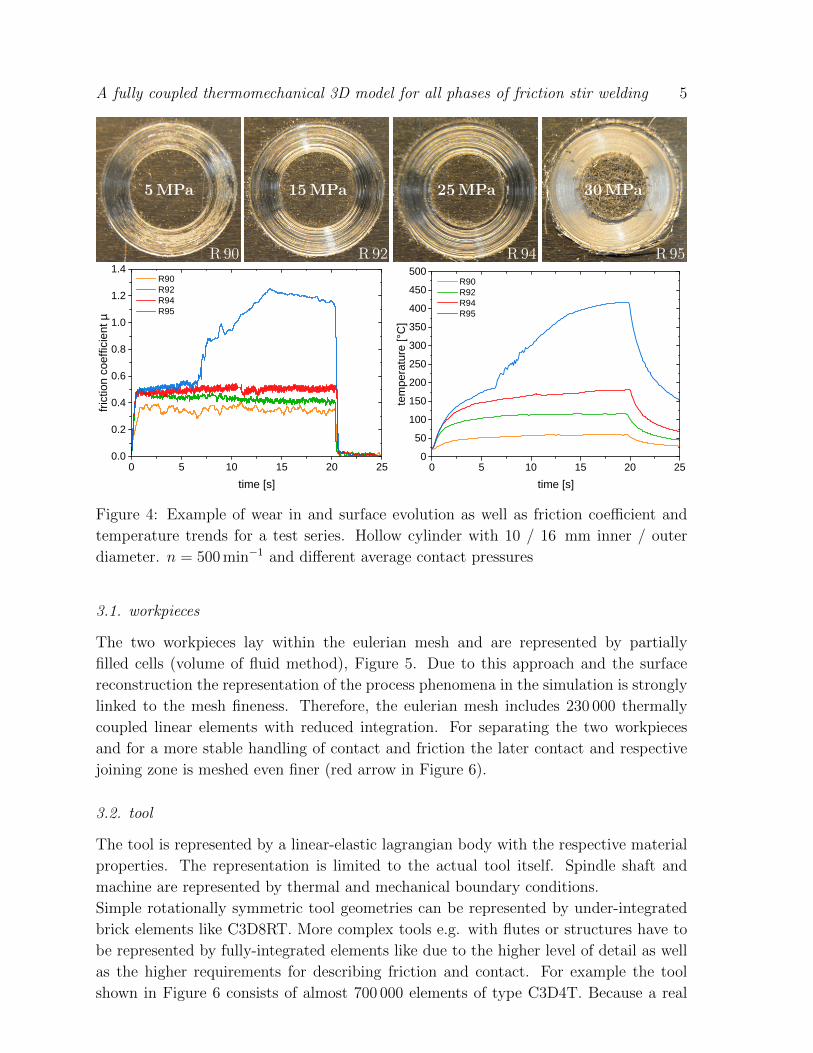
Figure 3. Overall 130 friction experiments with different normal pressures, spindle

speeds, geometries and contact areas were executed. A more detailed describtion can

be found in [5] as well. In general, the experiments showed an self-similar frictional

behavior. Figure 4 shows an example with stepwise increasing normal pressure. Initially

the system is dominated inherently by friction on oxide or absorption layers. Because

of the hard and durable aluminum oxides low or medium pressures and/or velocities

result in a only moderate wear of those layers. Therefore no metallic contact between

tool and base aluminum occurs, while to some extent the behavior is related to the well-

known Coulomb’s law, experiments R 90 to R 94 in Figure 4. With increasing pressure

or velocity the wear of the outer layers increases up to a point where those are distrubted

and a break-in of the tool takes place (R 95). By this a metallic contact between

aluminum and tool is established what causes an abrupt rise of forces respectively friction

coefficient, heat input and temperatures. In the shown example the heat flow density

increases from 5 W/mm2 to almost 15 W/mm2 by what the temperature rises from 175 C

A fully coupled thermomechanical 3D model for all phases of friction stir welding 4

Figure 3: frictional experimental: application of workpiece with thermocouples and

experimental setup with telemetric system, infrared camera and machine

to 425 C. Hereby the aluminum softens significantly and finally sticks to the tool causing

a self-enhancing effect on wear-in, heat input and also adhesion. Corresponding to the

real FSW process temperature and forces stabilize quickly.

After the transition the frictional interface ist strongly dominated by the material

behavior showing a manifest multi layer shearing (MLS) of the aluminum [5]. Because

of that the friction during FSW is not directly coupled to influences like normal force

and has to be expressed in dependence of temperature, interface velocity and stress

state. To provide this as well as a numerical stable implemention for this work an visco-

plastic friction law based on the Johnson-Cook material model was used to describe the

equilibrium of shearing stresses at the contact interface

τfriction =1√3σy,J−C (3)

=1√3σy(εv,pl , εv,pl , T ) (4)

3. Model

The basic model is composed of two eulerian workpieces and a lagrangian tool, adjacent

parts like anvil and fixture are modeled as lagrangian bodies as well. A schematic

model is shown in Figure 5, the setup in Abaqus/CAE including mesh and a example

tool geometry is Figure 6.

To enable the interaction between all parts independent and overlapping meshes

of eulerian and lagrangian formulation were used. The eulerian mesh is carried out in

a way so that it is well exceeding all designated contact areas with lagrangian bodies.

This allows a free material flow within the eulerian mesh after deformation and prevents

numerical diffusion efficiently.

A fully coupled thermomechanical 3D model for all phases of friction stir welding 5

R 90

5MPa

R 92

15MPa

R 94

25MPa

R 95

30MPa

0 5 1 0 1 5 2 0 2 50 . 00 . 20 . 40 . 60 . 81 . 01 . 21 . 4

R 9 0 R 9 2 R 9 4 R 9 5

frictio

n coe

fficien

t µ

t i m e [ s ]0 5 1 0 1 5 2 0 2 5

05 0

1 0 01 5 02 0 02 5 03 0 03 5 04 0 04 5 05 0 0

R 9 0 R 9 2 R 9 4 R 9 5

tempe

rature

[°C]

t i m e [ s ]

Figure 4: Example of wear in and surface evolution as well as friction coefficient and

temperature trends for a test series. Hollow cylinder with 10 / 16 mm inner / outer

diameter. n = 500 min−1 and different average contact pressures

3.1. workpieces

The two workpieces lay within the eulerian mesh and are represented by partially

filled cells (volume of fluid method), Figure 5. Due to this approach and the surface

reconstruction the representation of the process phenomena in the simulation is strongly

linked to the mesh fineness. Therefore, the eulerian mesh includes 230 000 thermally

coupled linear elements with reduced integration. For separating the two workpieces

and for a more stable handling of contact and friction the later contact and respective

joining zone is meshed even finer (red arrow in Figure 6).

3.2. tool

The tool is represented by a linear-elastic lagrangian body with the respective material

properties. The representation is limited to the actual tool itself. Spindle shaft and

machine are represented by thermal and mechanical boundary conditions.

Simple rotationally symmetric tool geometries can be represented by under-integrated

brick elements like C3D8RT. More complex tools e.g. with flutes or structures have to

be represented by fully-integrated elements like due to the higher level of detail as well

as the higher requirements for describing friction and contact. For example the tool

shown in Figure 6 consists of almost 700 000 elements of type C3D4T. Because a real

A fully coupled thermomechanical 3D model for all phases of friction stir welding 6

xy

ztool, lagrangian

eulerian volume

workpieces,eulerian, filled

vxvx

Figure 5: Schematic model assembly. isometrical, front and side view. Illustrated

without fixture, anvil and tool shank

tool geometry with flutes can be used for the simulation an active material transport

within the volume of revolution is possible, e. g. the pin shown in Figure 6 has a ratio

Vrotation / Vpin of 1.15.

3.3. simulation and implemention of process parameters

Process parameters are implemented on the one hand with the help of a reference point

on the tool’s center axis (movement or forge force in z, spindle speed etc). Through

this point properties like machine stiffness in x, y, z can be realized e.g. by spring

constraints. On the other hand the traverse speed vx is realized by velocity constraints

on the eulerian volume (in and out flow), see Figure 5.

For simulating the process the rotating tool plunges in a first step along the z axis

until the desired depth is reached. This position is held until the end of the dwelling

step. Then the traverse speed is applied on the eulerian volume (ramp) and and if

applicable the mode is switched to the virtually force control. After the desired length

of the weld is reached the traverse movement is stopped by decreasing in and out flow

speed to zero, then the tool is extracted from the joining zone again.

4. Results (excerpt)

4.1. weld geometry and process range

A feasible way to evaluate the quality of the simulation is to compare the surface

formation during the pluging step to experiments. This is because the plunging step

represents the highest gradient in FSW with a lot of transitions initiated or taking place

like contact and friction or material softening and flow which are strongly interacting

and linked to many (later) central process phenomena.

Figure 7 shows a comparison during the pluging step in experiment and simulation.

As shown all named phenomena evolve in the simulation according to reality and are

A fully coupled thermomechanical 3D model for all phases of friction stir welding 7

xy

z

Figure 6: Model assembly in simulation with mesh. isometrical and back view. partially

transparent eulerian volume

represented well. Even some more detailed events like the joint line dissolution (Fig. 7a)

or the formation of little “flakes” and the lip (Fig. 7c) can be predicted by the simulation.

An extended view of the fully plunged tool and a comparison with the process range

predicted in the simulation is given in Figure 8.

4.2. microstructure

Directly linked with the effective process range is the evolution of the microstructure.

Like shown in earlier work a quick and good estimate of size, shape and zones can be

made based on the accumulated strain [12, 3, 4]. This is primarily because the continuous

dynamic recrystallization (CDRX) can only occur where the material is deformed

to a quite high extend while it is simultaneously exposed to elevated temperatures.

Because of the self-stabilizing features of the process those two phenomena are mutually

dependent and result in the typical locally very limited process with high strain gradients

between Nugget, TMZ and base material. It should be mentioned that by this the

microstructure evolution is of course a function of the welded material. An example for

a microstructure prediction and named circumstance is given in Figure 9.

4.3. forces and temperature fields

Process forces can be directly read out on the reference point after the simulation. An

overview of detail and quality is given in Table 1. While the mean values match quite

well, minimum and maximum values differ. This can be lead back to the very different

sampling rate between simulation and experiment. Nevertheless, all simulation results

lay within the spread of the raw data of the telemetric system what is plausible.

A comparison of temperature fields and heat propagation of the related weld provides

Figure 10. In this context the asymmetric propagation along the joint line and the

warmer advancing side should be mentioned what correlates well with experiments.

A fully coupled thermomechanical 3D model for all phases of friction stir welding 8

(a) 0.5 mm plunging depth: distortion of joint line

(b) 3 mm plunging depth: formation of a “cup” with lip

(c) 4.8 mm plunging depth: everting material as the shoulder touches

Figure 7: evolution of the weld geometrie during plunging in experiment (left) and

simulation (right) in 5 mm EN AW-6061–T6 and the tool shown in Figure 6.

A fully coupled thermomechanical 3D model for all phases of friction stir welding 9

0 50 100 150 200 250 300 350 400 450 500 550 600 650 °C

Figure 8: material flow and process range 3©, pressure distribution below the tool on

anvil 4©: plunged tool with active structures and traverse cut of experiment

Nugget

TMZ 1 mm

Nugget

TMZ 1 mm

0 0,1 0,2 0,3 0,4 0,7 1,2 2,0 3,3 5,4 8,9 14,7 24,3 40,0 42,7

Figure 9: representation of weld geometry and microstructure. macro section

and simulation result (plastic equivalent strain). White accentuation for better

perceptibility.

A fully coupled thermomechanical 3D model for all phases of friction stir welding 10

ω vx ω vx

120 320 °C140 160 180 200 220 240 260 280 3000

Figure 10: comparison of temperature field in experiment (left) and simulation (right).

Asymetrical heat propagation on advancing and retreating side.

Table 1: comparison of process forces of the stationary state. Simulation average of 60

values / 1.5 sec, experiment of 2040 values / 1.2 sec. Min/Max experiment: raw data

of telemetric system (1700 Hz)

experiment simulationdifference

absolute relative

Fz

max 9920 N 8723 N −1197 N −12.0 %

8240N 8023N −217N −2.6%

min 7062 N 7278 N +216 N +3.0 %

Fx

max 1439 N 1317 N −122 N −8.4 %

1000N 998N −2N −0.2%

min 727 N 801 N +74 N +10.2 %

M

max 19.8 Nm 18.1 Nm −1.7 Nm −8.6 %

14.0Nm 16.5Nm +2.5Nm +17.8%

min 6.0 Nm 15.1 Nm +9.1 Nm +151.7 %

5. Summary

During this work the FSW process could be brought back to its underlying physics while

most assumptions and simplifications could be avoided. Based on the quantification of

the central process phenomena a 3D FE simulation method was developed that is able

to simulate real joint and detailed tool geometries and can predict material flow, void

and burr formation as well as process forces.

Acknowledgement

The author acknowledges support given by Deutsche Forschungsgemeinschaft (DFG) in

Project DFG RO 651/16-1 that was carried out at the Material Testing Institute (MPA)

at the University of Stuttgart.

A fully coupled thermomechanical 3D model for all phases of friction stir welding 11

Figure 11: left: level of tool detail reached in this study, right: welding of two sheets

into one and burr formation due to excessive plunging (tool not shown).

Literature

[1] W. F. Noh. Cel: A time-dependent, two-space-dimensional, coupled eulerian-lagrangian code.

Methods in Computational Physics, 3:117–179, 1964.

[2] Dassault Systemes. Modeling Extreme Deformation and Fluid Flow with Abaqus: V6 R6.12.

Velizy-Villacoublay, Frankreich, 2012.

[3] M. Hossfeld and E. Roos. A new approach to modelling friction stir welding using the cel method.

Advanced Manufacturing Engineering and Technologies NEWTECH 2013 Stockholm, Schweden,

pages 179–190, 2013.

[4] M. Hossfeld. Modelling friction stir welding: evolution of microstructure and weld geometry of

aluminium alloy en aw 6061. Proceedings of the 39th MPA-Seminar, Stuttgart, 2013.

[5] M. Hossfeld. Experimentelle, analytische und numerische Untersuchungen des Ruhrreib-

schweißprozesses. Dissertation, 2016.

[6] G. R. Johnson and W. H. Cook. A constitutive model and data for metals subjected to large strains,

high strain rates and high temperatures. Proceedings of the 7th International Symposium on

Ballistics, 21, 1983.

[7] M. Spittel and T. Spittel. Thermal expansion of light metal alloys. In H. Warlimont, editor, Part

2: Non-ferrous Alloys - Light Metals, volume 2C2 of Landolt-Bornstein - Group VIII Advanced

Materials and Technologies, pages 92–95. Springer, 2011.

[8] D. C. Prasso, J. W. Evans, and I. J. Wilson. Heat transport and solidification in the

electromagnetic casting of aluminum alloys: Part i. experimental measurements on a pilot-scale

caster. Metallurgical and Materials Transactions B, 26(1):1243–1251, 1995.

[9] D. C. Prasso, J. W. Evans, and I. J. Wilson. Heat transport and solidification in the

electromagnetic casting of aluminum alloys: Part ii. development of a mathematical model and

comparison with experimental results. Metallurgical and Materials Transactions B, 26(1):1281–

1288, 1995.

[10] K. C. Mills. Recommended values of thermophysical properties for selected commercial alloys.

Woodhead, Cambridge, 2002.

[11] R. C. Picu, G. Vincze, F. Ozturk, J. J. Gracio, F. Barlat, and A. M. Maniatty. Strain rate

sensitivity of the commercial aluminum alloy aa5182-o. Materials Science and Engineering: A,

390(1-2):334–343, 2005.

[12] S. Guerdoux and L. Fourment. A 3d numerical simulation of different phases of friction stir

welding. Modelling and Simulation in Materials Science and Engineering, 17(7):075001, 2009.


Recommended