Page 1
Middle East Technical University
Department of Computer Engineering
Arınç Elhan – 1819291
Halim Görkem Gülmez – 1819382
Muhammet Furkan Yılmaz – 1881630
Yiğit Kardelen – 1819424
January 4, 2014
Adamadama Development
A Game of Multitasking
Software Design Description Document
Page 2
2
Preface
This is the official document of Software Design Description (SDD) of “ A Game of
Multitasking”. This document is prepared according to the “IEEE Standard for Information
Technology – Systems Design - Software Design Descriptions. IEEE Std 1016 – 2009”. Main
purpose of this document is to give detailed information about the design description of the
project such as design elements, development and design process of the software product.
Page 3
3
Publishing Dates of Original and Changed
Subjects
Revision Date Changes
0 03.01.2015 Original Copy
1 01.03.2015 Viewpoint diagrams are updated, grammar corrections are made and the plan is added to conclusion part.
Page 4
4
Table Of Contents
1. Overview .............................................................................................................................................. 6
1.1. Scope ............................................................................................................................................ 6
1.2. Purpose ......................................................................................................................................... 6
1.3. Intended Audience ....................................................................................................................... 6
1.4. References .................................................................................................................................... 6
2. Definitions ........................................................................................................................................... 7
3. Conceptual Model for Software Design Descriptions ......................................................................... 8
3.1. Software Design in Context .......................................................................................................... 8
3.2. Software Design Descriptions within Life Cycle ........................................................................... 8
3.2.1. Influences on SDD Preparation ............................................................................................. 8
3.2.2. Influences on Software Life Cycle Products .......................................................................... 8
3.2.3. Design Verification and Design Role in Validation ................................................................ 9
4. Design .................................................................................................................................................. 9
4.1. Introduction .................................................................................................................................. 9
4.2. SDD Identification ......................................................................................................................... 9
4.3. Design Stakeholders and Their Concerns ................................................................................... 10
4.4. Design Views ............................................................................................................................... 10
4.5. Design Viewpoints ...................................................................................................................... 10
4.6. Design Elements ......................................................................................................................... 10
4.7. Design Overlays .......................................................................................................................... 10
4.8. Design Rationale ......................................................................................................................... 11
4.9. Design Languages ....................................................................................................................... 11
5. Design Viewpoints ............................................................................................................................. 12
5.1. Introduction ................................................................................................................................ 12
5.2. Context Viewpoints .................................................................................................................... 12
5.2.1. Design Concerns .................................................................................................................. 12
5.2.2. Design Elements .................................................................................................................. 14
5.3. Composition Viewpoint .............................................................................................................. 14
5.3.1. Design Concerns .................................................................................................................. 14
5.3.2. Design Elements .................................................................................................................. 15
5.4. Logical Viewpoint ....................................................................................................................... 16
5.4.1. Design Concerns .................................................................................................................. 16
Page 5
5
5.4.2. Design Elements .................................................................................................................. 17
5.5. Information Viewpoint ............................................................................................................... 19
5.5.1. Design Concerns .................................................................................................................. 19
5.5.2. Design Elements .................................................................................................................. 19
5.6. Interaction Viewpoint ................................................................................................................. 20
5.6.1. Design Concerns .................................................................................................................. 20
5.7. Pattern Viewpoint ...................................................................................................................... 23
5.8. Interface Viewpoint .................................................................................................................... 23
5.9. State Dynamics Viewpoint .......................................................................................................... 27
5.9.1. Design Concerns .................................................................................................................. 27
5.9.2. Design Elements .................................................................................................................. 28
6. Conclusion ......................................................................................................................................... 29
Page 6
6
1. Overview
1.1. Scope
This document elaborately gives the design description for the project. To specify and
explain in detail, the development and design process of the software product, design elements
and the viewpoints will be given in this document. Each design concern is expressed in the
context of one design view and each design view is given with the corresponding design
elements. To sum up, the document provides a clear understanding of the basic structure of the
project and how the implementation process will be carried out.
1.2. Purpose
The software design document provides the system modeling and architectural design
for the project. The main and most important purpose of this document is to provide an overall
description of design elements, how they are interacting with each other, the content of
system’s components and behavior prior to the code development phase. It can also be said that
software design description is very important and credentials for people who will be involved in
code development. In other words, this document verifies whether the design issues conform to
the requirements of the project’s SRS Document. SDD serves as the primary reference for the
code development.
1.3. Intended Audience
As stated in section “1.2. Purpose” of the project SRS document, the intended audience are
developers, testers and end users. The design document gives detailed explanation of data,
architecture (design viewpoints) and procedural design for the developers and testers. The end users
can also be guided by system components, boundaries, restrictions and services description in this
document.
1.4. References
The resources listed below are the references that has been used during the preparation of
this document; IEEE Standard Documents:
[1] IEEE (2009). IEEE Standard for Information Technology – Systems Design - Software Design
Descriptions. IEEE Computer Society.
[2] Unity UI. (n.d.). Retrieved December 30, 2014, from http://unity3d.com/
[3] Parse. (n.d.). Retrieved December 28, 2014, from http://www.parse.com/
[4] 2D Game Development Walkthrough. (n.d.). Retrieved December 31, 2014, from
http://unity3d.com/learn/tutorials/modules/beginner/2d/2d-overview
Page 7
7
[5] How to create an online multiplayer game with Unity. (n.d.). Retrieved January 2, 2015,
from http://www.paladinstudios.com/2013/07/10/how-to-create-an-online-multiplayer-game-with-
unity/
[6] “A Game of Multitasking” Software Specification Requirements (SRS) Document.
Retrieved December 31, 2014.
[7] StarUML 5.0 User Guide. (2005). Retrieved December 30, 2014, from
http://staruml.sourceforge.net/docs/user-guide (en)/toc.html
2. Definitions
Database: A collection of related data about user scores.
DBMS: A software package/system to facilitate the creation and maintenance of a
computerized database.
User: Person who can play single/multiplayer mode of the game.
SRS: Software Requirements Specifications.
SDD: Software Design Descriptions.
Class Diagram: A type of static structure diagram in UML that describes the structure of a
system by showing the system’s classes, their attributes, operations (or methods), and
the relationship among the classes.
Use Case Diagram: A type of diagram in UML that represents the user’s interaction with
the system.
Sequence Diagram: An interaction diagram that shows how processes operate with one
another and in which order.
State Diagram: A type of diagram used for describing the behavior of systems.
System Context Diagram: A type of diagram that defines the boundary between the
system, or part of a system, and its environment, showing the entities that interact with
it.
System Component Diagram: A type of diagram that are used to illustrate the structure
of complex systems.
System Deployment Diagram: A type of diagram that are used to describe the static
deployment view of a system.
Composite Structure Diagram: A type of diagram that shows the internal structure of a
class and the collaborations that this structure makes possible.
ER Diagram: A data model, which defines the information and data aspects of the
database.
Unity 3D: A cross-platform game creation system developed by Unity Technologies,
including a game engine and integrated development environment.
Game Engine: Software framework designed for the creation and development of video
games.
Page 8
8
IDE: Software application that provides some good and useful facilities to programmers
for software development.
IEEE: The Institute of Electrical and Electronics Engineers.
FPS: Frame per second.
Scene: In unity, every different screen is represented as scene.
Interface: The part that can be shown by users of the game.
UML: Unified Modeling Language.
Parse: A hosted service, providing backend services to end-user.
GCE API: Google Compute Engine Application Interface
3. Conceptual Model for Software Design
Descriptions
This section includes basic project terms, concepts and context of SDD in which the
documentation is prepared. The conceptual model aims to give a better understanding of the
project terminology, software life cycle and modules that the project resides on.
3.1. Software Design in Context
The software product will be designed in an object-oriented and modular fashion. This
project will be implemented with C# using Unity and Monodevelop as IDE. The software product
is planned to be a game where unity is the game engine. The product will be designed for mobile
devices such as smart phones and tablets. Different operating systems such as Android and IOS
will be an issue. Supporting different screen resolutions and screen aspects will also be an issue.
For multiplayer mode Parse will be used as server side for communicating devices. Security is
handled by Parse. Cloud code will be written in Javascript and frontend communicating functions
will be written in C#. Once the devices learn which device to connect, pear to pear (P2P)
connection will be established. This connection will be wrote with C# using Unity server aspects.
3.2. Software Design Descriptions within Life Cycle
3.2.1. Influences on SDD Preparation
As it can be guessed, the main influence on software design description preparation is
the A Game of Multitasking software requirements specification document. The product
perspective, functional and nonfunctional requirements determine the outline of the
architectural design. The additional specifications of the stakeholders related to the frameworks
or data affect the SDD preparation.
3.2.2. Influences on Software Life Cycle Products
The agile method is adopted for the software process model and the software product
will reach to a final stage after a series of iterations. The first part of the software cycle is to
Page 9
9
construct multiple mini games which are controlled by different controllers. The next part is to
merge mini games. After the first iteration a prototype will be presented to the stakeholders.
The iterations and additional/changing requirements of the stakeholders have influence on
software life cycle products. After the first demo, single player mode will be finished. The next
part will be constructing the server and handling the multiplayer mode which is the main
concern of the project.
3.2.3. Design Verification and Design Role in Validation
The main credentials for verification and validation of whether design of software obeys
the requirement that are specified in A Game of Multitasking SRS Document. The requirements
for each specific intended use of the software product are modeled in the design view parts of
the document. The verification and validation of the design view models are carried out based
on this document. SDD influences test plans and test cases in further stages. The testing process
will be handled after the code development.
4. Design
4.1. Introduction
The Software Design Description of this project is prepared for giving an overall
architectural design of “A Game of Multitasking” mobile game. In the following sections,
information about Identification of the SDD, identified design stakeholders, identified design
concerns, selected design viewpoints, each with type definitions of its allowed design elements,
design views, design overlays, design rationale and design languages can be found in this order.
4.2. SDD Identification
The system model that is specified in this SDD will be used for each production step
during the development and implementation periods. After the initial iterations, the prototype
will be demonstrated on January 19, 2015. The software product will be released by the end of
May 2015. Tentative date for the
Releasing project will be May 22, 2015. Adamadama development team will be responsible for
issuing “A Game of Multitasking” project. All rights of the end product are reserved. Due to the
exclusive right property, only Adamadama development will be free to modify and distribute the
product. Again, due to the privacy and copyright of the user data, user profiles cannot be
distributed. Apart from these and in order to avoid repetition, Glossary and necessary
terminology is available in section “2. Definitions” and also scope, references, context and
summary can be found in section “1. Overview”.
Page 10
10
4.3. Design Stakeholders and Their Concerns
Stakeholders include Adamadama Developers team, testers and end users. Stakeholder’s
main concerns are performance, reliability and real time interaction without any delay or lag.
The final software product is planned and expected to be smooth, fast and reliable which will
overcome these concerns. “A Game of Multitasking” is a unique mobile game that aims to fuse
multitasking and mobile gaming. Two main modes will be available when the game is released.
Any further requirements are pointed in the Software Requirements Specification document of
the “A Game of Multitasking” project.
4.4. Design Views
This project will be implemented as mobile game application with different control
mechanisms as two different modes namely single player mode and multiplayer mode.
Therefore, stakeholders can download and play the game in a single player mode as long as they
have mobile phone that supports android or iOS. For the multiplayer mode, they need also good
and smooth Internet connection.
In this document; contextual, composition, interface, logical, interaction and state
dynamics view will be explained in next sections. Detailed description and diagrams about these
views will clarify them. Each view is given with its corresponding viewpoint.
4.5. Design Viewpoints
Software design description identifies context, composition, interface, logical, interaction
and state dynamics viewpoints. Context viewpoint specifies the system boundaries and actors
interacting with the system. Composition viewpoint identifies the system modules, components,
frameworks and system repositories. Interface viewpoint explains the interaction between
different software interfaces. Logical viewpoint includes the detailed description of data design
and class diagrams. Interaction viewpoint gives the sequence of events in the system and the
state dynamics viewpoint models the system as a state machine and shows the state transitions
and conditions on these transitions.
4.6. Design Elements
As a general description, a design element is any item that occurs in a design view. All of
the design elements of this SDD are described and explained in the following sections. Design
elements, their main properties, interactions and restrictions on elements are given together
with the viewpoints that are related to. These main design elements are defined inside the
related viewpoints in detail in section “5. Design Viewpoints”.
4.7. Design Overlays
A design overlay is used to indicate extra information with respect to an already defined
design view. The UI Component in this project refers to the interface of the mobile application
Page 11
11
interface that is shown by user. Its main purpose is to show the current games, main menu or
score to the user. In addition, receiving inputs and displaying results is another main purpose of
this component.
4.8. Design Rationale
Software design pattern is a common reusable solution to a commonly occurring
problem within the context in software design. A design pattern is not a completed design that
can be converted directly into source or machine code. It is a definition or template for how to
solve a problem that can be used in many different situations.
This project is aimed and planned to be a mobile platform game. There are some games
on mobile markets that have the theme of multitasking but they are boring, simple and
unsatisfying from the point of view of users. So, in order to create much more entertaining and
unique game, this project has been chosen.
The project is based on creating an entertaining and a unique game with a multitasking
theme, which runs on the mobile platforms. There are several mini games in the project and
each one will be played with a different mechanism of the device such as virtual joystick with
one game or accelerometer with another game. In the single player mode, there are several
different mini games (three or four) that will be played when the game starts. Player will play
those mini games by using different control mechanisms of the device such as accelerometer or
virtual joysticks. In the multiplayer mode, players will connect to the same mini games and play
at the same time in order to compete each other. One of the mini games is about disrupting
other player’s mini game.
Designing four different mini games is a big issue. So, in order to handle it easily and in a
quick manner, Unity3D game engine has been chosen, in other words games will be developed
using Unity3D. Showing and playing four different mini games at the same time with one screen
is another big issue. So, using a game engine for handling this situation is much more easier than
native approach. Finally, adding an online multiplayer mode to game is another hard task to
achieve. Users will see both the opponent’s game and theirs game real-time. The game can be
won if the opponent loses the game. The connection between two devices will be established by
peer-to-peer architecture. There will be an external server, which stores current active
connections. Clients (devices) will be in interaction with the server only for playing multiplayer
mode. So, in order to handle connection issues, unity’s multiplayer API will be used.
4.9. Design Languages
In this document Unified Modeling Language (UML) is used as the modeling language for
the diagrams that is related with the system and architecture of the project. To emphasize the
static structure and dynamic behavior of the system, UML is used. In addition, ER diagram is
used for the design viewpoint specification (Like showing database structure).
Page 12
12
5. Design Viewpoints
5.1. Introduction
With the help of the architectural models, notations, and languages, design viewpoints
are used to specify the methods for a system. The design descriptions and constraints of “A
Game of Multitasking” are being realized by using these design viewpoints. Different design
viewpoints are given in the following subsections. The design language is UML.
5.2. Context Viewpoints
Actor interactions of “A Game of Multitasking” and boundaries of the system are
represented in this section. The relationship between “A Game of Multitasking” and external
systems is shown within the system environment. UML Use Case diagram is used in order to
provide the roles of actors.
5.2.1. Design Concerns
“A Game of Multitasking” offers only one service to the one actor, which is player.
Players are able to register and then login to the game. The player can play the single player
mode without this login operation. Also while playing this mode, the game does not require any
internet connection: this mode can be played offline. In this mode, the player can pause and
continue the game via graphical user interface of the game. The player can also see about
section, change his/her preferences in offline mode. In online mode, the player can change
his/her nickname, search a multiplayer match, play a multiplayer match, remove advertisements
by paying an amount, share scores, and see leaderboards. These actions require internet
connection to be able to communicate with related systems.
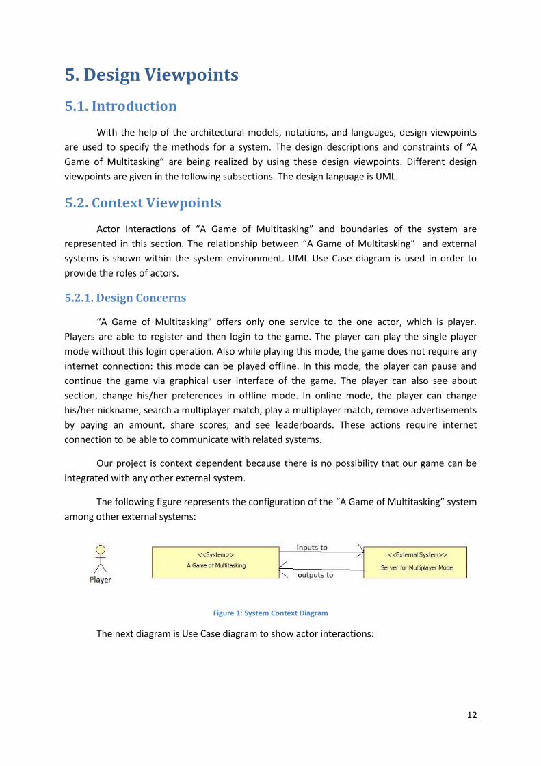
Our project is context dependent because there is no possibility that our game can be
integrated with any other external system.
The following figure represents the configuration of the “A Game of Multitasking” system
among other external systems:
Figure 1: System Context Diagram
The next diagram is Use Case diagram to show actor interactions:
Page 13
13
Figure 2: Use Case Diagram
System
Player
Play Multiplayer
Play SinglePlayer
About
Pause
Continue
Share
Leader Boards
Login
Change User Name
Cancel Searching
Register
Steer
Tap
Swipe
Remove Ads
Preferences
See Tutorial
Page 14
14
5.2.2. Design Elements
The group of stakeholders is one of the important design entities. For our project, as the
game is developed by us and any income will be shared between us, only stakeholder is our
team. This may change after the release of the game, if the game is bought by some company.
The other group of design entities is player actors. The player actor is who interacts with the
game. All those interactions are represented in the Use Case diagram. While the player actor
plays the online mode the game will send input to server, and then take the output. In the single
player mode, there will be no communication between the game and the server.
5.3. Composition Viewpoint
In this section, project components and connections between these components are
explained in detail. Explanations are enriched with diagrams and figures.
5.3.1. Design Concerns
This viewpoint aims to inform both programmers and stakeholders. Moreover, thanks to
the representation of the system, connecting components and scheduling the progress are much
easier.
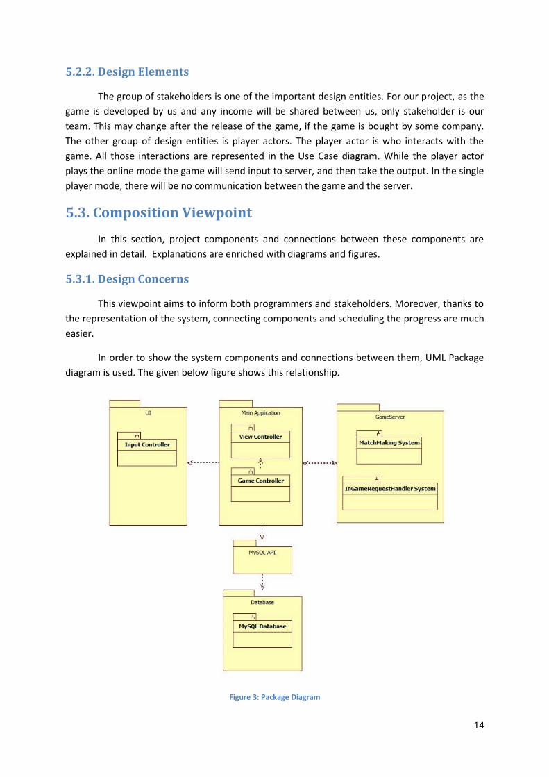
In order to show the system components and connections between them, UML Package
diagram is used. The given below figure shows this relationship.
Figure 3: Package Diagram
Page 15
15
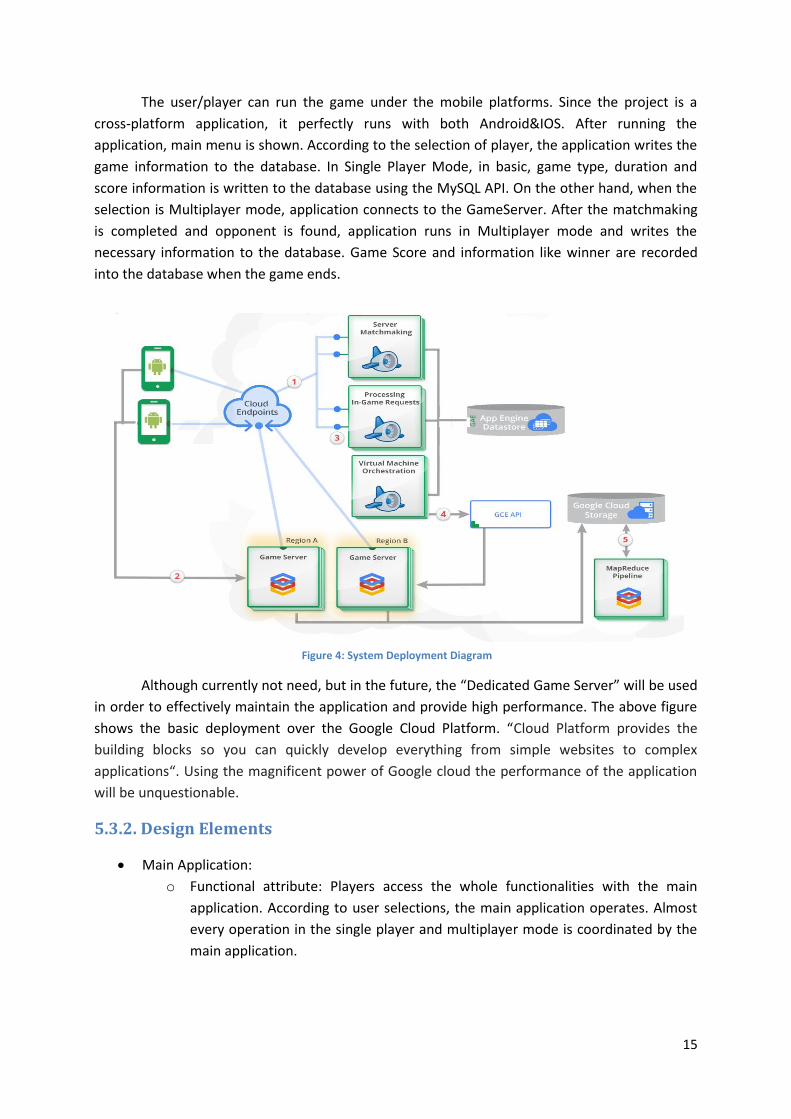
The user/player can run the game under the mobile platforms. Since the project is a
cross-platform application, it perfectly runs with both Android&IOS. After running the
application, main menu is shown. According to the selection of player, the application writes the
game information to the database. In Single Player Mode, in basic, game type, duration and
score information is written to the database using the MySQL API. On the other hand, when the
selection is Multiplayer mode, application connects to the GameServer. After the matchmaking
is completed and opponent is found, application runs in Multiplayer mode and writes the
necessary information to the database. Game Score and information like winner are recorded
into the database when the game ends.
Although currently not need, but in the future, the “Dedicated Game Server” will be used
in order to effectively maintain the application and provide high performance. The above figure
shows the basic deployment over the Google Cloud Platform. “Cloud Platform provides the
building blocks so you can quickly develop everything from simple websites to complex
applications“. Using the magnificent power of Google cloud the performance of the application
will be unquestionable.
5.3.2. Design Elements
Main Application:
o Functional attribute: Players access the whole functionalities with the main
application. According to user selections, the main application operates. Almost
every operation in the single player and multiplayer mode is coordinated by the
main application.
Figure 4: System Deployment Diagram
Page 16
16
o Subordinates attribute: There is only one main application and it is stand-alone.
Due to this, it does not contain any other application. However, it interacts and
communicates with both database and GameServer.
Database:
o Functional attribute: MySQL database stores data about players, history and
played games.
o Subordinates attribute: MySQL API connect database to the main application.
UI:
o Functional attribute: User interface of the main application displays main menu,
selection scenes, multiplayer mode scenes and control operations/inputs done
by users.
o Subordinates attribute: UI contains view and controller components. View
component displays menus and buttons. Controller checks the selected buttons
or the other actions.
GameServer:
o Functional attribute: According to subscribed players, the appropriate
matchmaking is done. Additionally, the In-Game requests are handled.
o Subordinates attribute: GameServer is a stand-alone component. It does not
contain any other component.
5.4. Logical Viewpoint
In this section, briefly detailed designed types and the practical implementation in a
logical standard are examined. The illustration will be based on classes and diagram will be used.
5.4.1. Design Concerns
This section gives detailed information about the organization of the classes. Classes of
the system are designed in the object oriented manner. In addition to that, during the
development, class designs may be changed in order to provide some functionality. However,
the general structure will remain same. Details about the classes will be given 5.4.2.
Page 17
17
Figure 5: Class Diagram
5.4.2. Design Elements
There are 16 classes in the class diagram. Each class will be detailed below.
GameType: An enumeration which indicates the type of the game. The options
are ‘SinglePlayerMode’ and ‘MultiPlayerMode’.
GameStats: This class represents the overall statistics about the games that have
been played by the user. Each Player must hold a reference to that class.
GameController: This class represents and holds the general functionalities in the
game. GameController is run whenever a game is started. According to the user
activities, it has capability to pause/continue the game. Additionally, the distance
server connection and database connection is mainly controlled under this class.
The key and vital class in the application is the GameController class.
DBConnector: This class has capability to manage all database operation. It uses
the MySQL API and makes appropriate operations. In addition to this, it has
throwing special the exceptions and logging mechanism. The only class that can
control and reference to this class is GameController. This structure is built in
order to make the system single-control.
Page 18
18
UI: UI class is responsible for user-interaction. Every command or input received
from the player is handled in this class. Each Player must hold a reference to this
class. Although currently stated as eight functional capabilities, in the next phases
of the project, more functionality will be brought to this class.
Player: The Player class represents and holds the generic information about the
player/user. Moreover, it holds references to the many other classes and this
class is used as an instance.
GameServer: This class represents the game server. In addition to indicated
capabilities, this class internally handles the in-game requests in a tremendously
fast manner. The only external package is the Server package and this is the only
class in it. Only communication with GameServer class is done by
GameController.
Game: This class represents the game and its content. Mainly the scene of the
game is held here.
Scene: Scene class holds the entire information about the game scene. In other
words, every details and knowledge is restored here in order to be controlled by
the game controller.
GameObject: Everything in the Unity environment is the game object. Every
component created on the scene will be the GameObject instance. In addition,
this class hold every information about the component on the scene.
Component: Each GameObject will have their own components with carries
physical properties about the GameObject.
AbstractGameScript: This abstract class is generated for the mini games scripts. In
order to achieve a good object oriented design, a generic script class is designed.
This class is the parent class of the mini game script classes.
FirstGameScript: This class is designed and created for the first game. It extends
the “AbstractGameScript” classes. Moreover, additional functionalities that are
specific for this mini game will be added in the following phases of the project.
SecondGameScript: This class is designed and created for the second game. It
extends the “AbstractGameScript” classes. Moreover, additional functionalities
that are specific for this mini game will be added in the following phases of the
project.
ThirdGameScript: This class is designed and created for the third game. It extends
the “AbstractGameScript” classes. Moreover, additional functionalities that are
specific for this mini game will be added in the following phases of the project.
FourthGameScript: This class is designed and created for the fourth game. It
extends the “AbstractGameScript” classes. Moreover, additional functionalities
that are specific for this mini game will be added in the following phases of the
project.
Page 19
19
5.5. Information Viewpoint
This section provides detail for designed types and their implementations in a
informative way by using entity relationship structures.
5.5.1. Design Concerns
Although data are not the most important part of this project, there are some tables to
keep necessary information about the player. Especially for online functionalities, these data
must be kept.
Related entity relationship diagram is given below:
Figure 6: ER Diagram
There are two tables in database, namely Player, and GameStats. “Player” is keeping
information about players. “GameStats” is keeping statistics of the players. Details will be given
in Section 5.5.2.
5.5.2. Design Elements
ER diagram, which is given in 5.5.1., contains two entities:
“Player” entity contains fields about the player who can play the game. Fields of this
entity are given below:
userID: This attribute is primary key of this entity. This id is unique and used to
retrieve necessary statistics about the player.
userName: This attribute contains the user name of the player.
email: This attribute contains the email of the player.
paidAccount: This attribute is a Boolean attribute which is used while deciding
whether to show advertisements to player or not. If an account is a paid account,
then the player will not see any advertisements.
“GameStats” entity contains fields about the statistics of the players. These statistics will
also be used for matchmaking:
userID: This attribute is a foreign key in this entity. This id is unique and used to
retrieve each player’s own statistics.
Page 20
20
numberOfPlayedGame: This attribute keeps the number of the games that the
player has played so far.
numberOfWins: This attribute keeps the number of the games that the player has
won so far.
numberOfLoses: This attribute keeps the number of the games that the player
has lost so far.
totalPoints: This attribute keeps the total point that the player has gained so far.
highScore: This attribute keeps the high score of the player.
5.6. Interaction Viewpoint
To describe main functionalities (what use cases do, how user interacts with the system),
some example UML Sequence Diagrams are given in this section.
5.6.1. Design Concerns
Purpose of this view is giving details about the process of the application. As there are
lots of sequences in our project, emphasis will be put on the most important ones. Given UML
Sequence Diagrams below will represent the behavior of the system and classes for the
important use cases. These diagrams will be interpreted in detail, too.
First sequence diagram is given below and it will describe the login operation for “Player”
class:
Figure 7: Sequence Diagram for Login Operation
When a player wants to login, he/she gives his/her login information to the game’s initial
screen. Then, the game calls login method. This method sends a query to the database. Database
returns whether this information is true or not. If it is true, the main menu comes up. Otherwise,
Page 21
21
user will see an error saying that the login information is not correct. Still, the player can pass
this login operation but in this case, he/she cannot use online interactions.
Next sequence diagram will show what happens when the player wants to play
multiplayer mode:
Figure 8: Sequence Diagram for Multiplayer Mode
When the player wants to play the multiplayer mode (assuming he/she is logged on),
there will be a matchmaking process to find an opponent and a room. If both of them are found,
then the match can begin, otherwise there will be an error message.
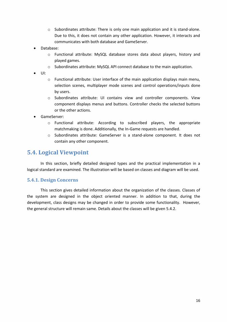
Following sequence diagram give details about updating an account’s payment detail:
Page 22
22
Figure 9: Sequence Diagram for advertisement removing
When the player wants to remove, he/she has to make a payment. After this payment is
done, changeAccountDetails method will be called and this method will send a query to
database. In the database, related field will be updated. From then, that user will not see
advertisements any more.
A final example sequence diagram will describe what happens when a player tries to
pause the game:
Figure 10: Sequence Diagram for Puase Game Operation
Page 23
23
The player has an option to pause the game while playing the single player mode. This
can be done by tapping to the pause button on the screen. Then this button (UI element) call its
pauseGame method. This method will call the game’s pause method. Finally, the game will be
paused.
5.7. Pattern Viewpoint
Pattern viewpoint mainly concerns reuse of patterns and available Framework template.
Composite structure diagram is a type of static structure diagram which indicates the internal
structure of a class and the collaborations that this structure makes possible.
In order to provide a deeper understanding of this viewpoint, a composite structure
diagram is provided below.
Figure 11: Composite Structure Diagram
5.8. Interface Viewpoint
As it can be inferred from the name, Interface view specifies a determined contract
among the designers, customers, programmers, and testers. In this section, the user interfaces
that will be developed will be detailed with screens to indicate how the interface will be like. The
images used in this section are retrieved from the initially developed application. No wonder
that view of scenes and menus might change a little during the development and
implementation phases. Nevertheless, screen will have structure similar to these ones.
The initial screen of the application can be seen below. The player selects one of the
game types using the buttons. According to the selection of the player, application directs player
to another screen. The logo and background is currently chosen as this. More eye-opening and
fascinating logo and background images will be designed in the following phases of the project.
Page 24
24
After user/player selects the game type, assuming player in single player mode, the game
selection screen will be shown to the user. The player will choose which game(s) he/she wants to
play. Each game is represented with their distinctive object that is used in that game. There is
also a button on the top-right of screen. Using this button, player can go back to the main menu.
The below screens are retrieved from each mini game in order to show the interfaces.
The first mini game screenshot is given below. It is a balancing game and player tries to
hold the ball in balance. According to the accelerometer of the mobile device, the bar moves.
Figure 12: Screenshot of the initial menu
Figure 13: Screenshot of the game selection menu
Page 25
25
The second mini game screenshot is given below. It is a reflex game in which the player's
purpose is to get away from incoming projectiles. The current images of spaceship and
projectiles are have chance to change according to coming feedbacks from the test players.
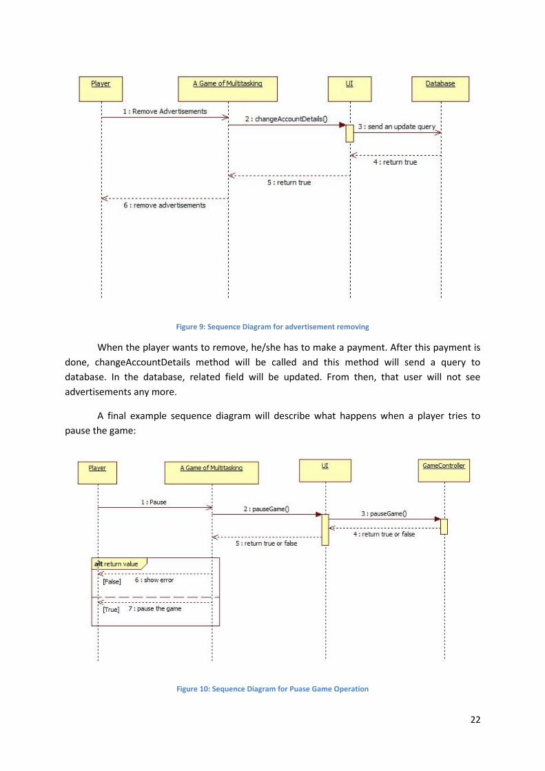
The third mini game screenshot is given below. It is a catching game, where the player
controls a bucket to catch the balls falling from the top of that part of the screen. The score is
shown at the middle top of the screen, which is actually a timer.
Figure 14: Screenshot of the first game
Figure 15: Screenshot of the second game
Page 26
26
And finally the fourth game screenshot is given below. It is a run-and-jump game, in
which the player controls a runner who has to jump over the obstacles that are coming on the
right side of the screen. As in all other mini games, the score is shown at the middle top of the
screen, which is actually a timer.
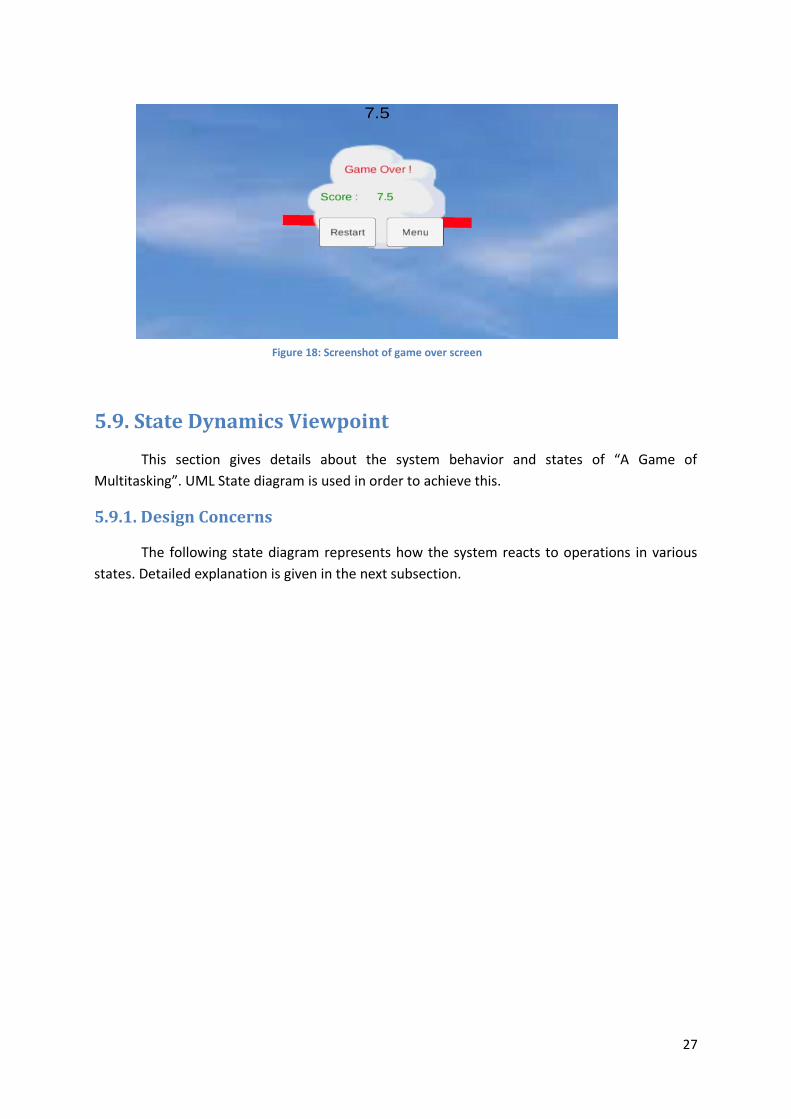
Whenever the players fails, the game over screen will be shown to the player. The
sample game over screen can be seen below. It shows the score and has two buttons. Using this
buttons, the player can restart the game or go back to the menu.
Figure 16: Screenshot of the third game
Figure 17: Screenshot of the fourth game
Page 27
27
5.9. State Dynamics Viewpoint
This section gives details about the system behavior and states of “A Game of
Multitasking”. UML State diagram is used in order to achieve this.
5.9.1. Design Concerns
The following state diagram represents how the system reacts to operations in various
states. Detailed explanation is given in the next subsection.
Figure 18: Screenshot of game over screen
Page 28
28
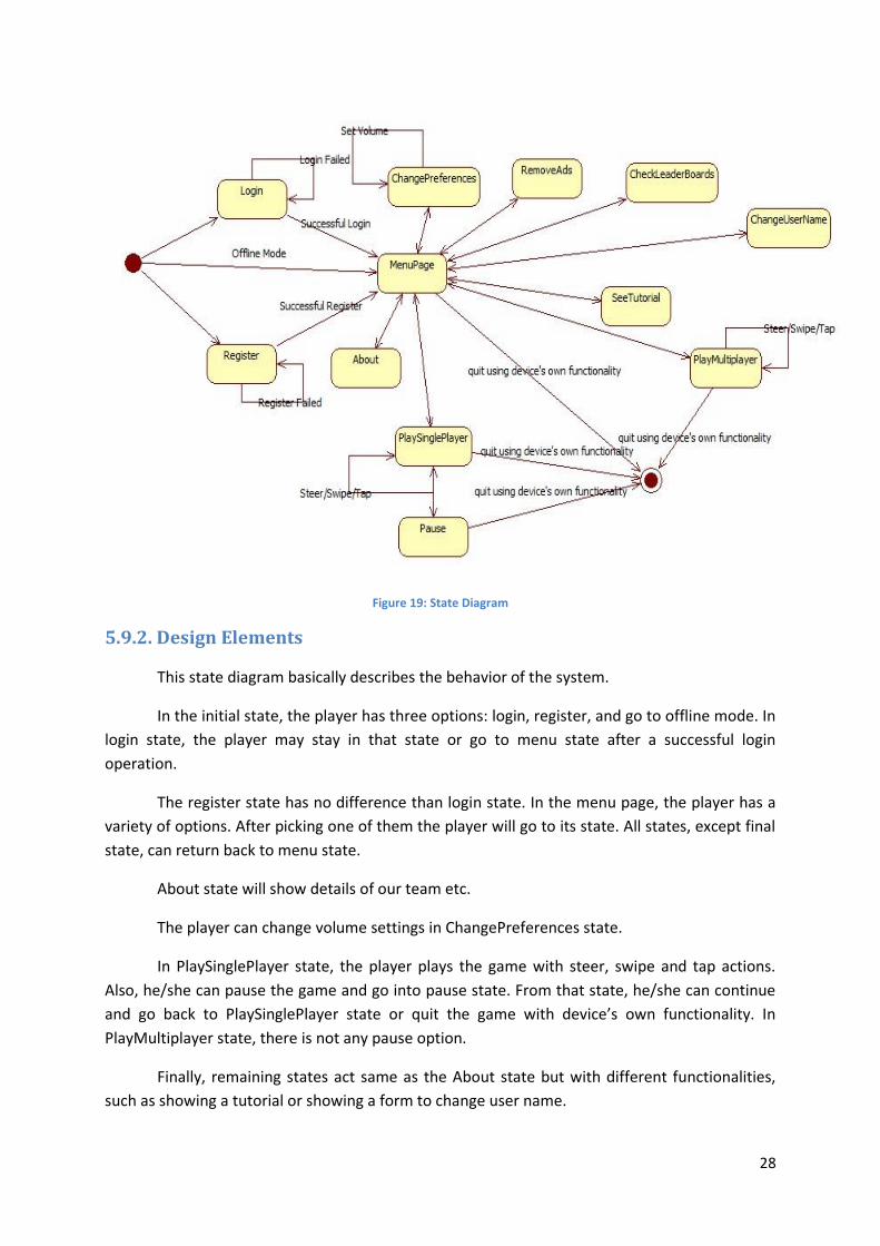
Figure 19: State Diagram
5.9.2. Design Elements
This state diagram basically describes the behavior of the system.
In the initial state, the player has three options: login, register, and go to offline mode. In
login state, the player may stay in that state or go to menu state after a successful login
operation.
The register state has no difference than login state. In the menu page, the player has a
variety of options. After picking one of them the player will go to its state. All states, except final
state, can return back to menu state.
About state will show details of our team etc.
The player can change volume settings in ChangePreferences state.
In PlaySinglePlayer state, the player plays the game with steer, swipe and tap actions.
Also, he/she can pause the game and go into pause state. From that state, he/she can continue
and go back to PlaySinglePlayer state or quit the game with device’s own functionality. In
PlayMultiplayer state, there is not any pause option.
Finally, remaining states act same as the About state but with different functionalities,
such as showing a tutorial or showing a form to change user name.
Page 29
29
6. Conclusion
A Game of Multitasking Project’s implementation details, system architecture, and
design patterns are represented and explained in this Software Design Description document.
Fundamentals of data design, modules, and viewpoints are also included in this document. UML
diagrams are frequently used in the preparation of this document. Finally, with the help of the
design viewpoints, design issues are described in a detailed manner. Our plan is to complete a
playable version of the single player mode first, by complying with this document. After then, a
multiplayer mode will be developed. When that mode becomes playable, too, we are going to
publish our game in mobile markets. There will be regular updates in order to fix bugs (if any)
and add new modes/minigames.


![Cognitive Predictors of a Common Multitasking Ability ...mjkane/pubs/Redick et al 2016, JEPG [multitasking].pdfCognitive Predictors of a Common Multitasking Ability: Contributions](https://static.documents.pub/doc/80x56/5af43c547f8b9a74448c98a4/cognitive-predictors-of-a-common-multitasking-ability-mjkanepubsredick-et.jpg)


