83
A Guide to Dynamic Weighing for Industry The Institute of Measurement and Control 87 Gower Street London WC1E 6AF October 2010
A Guide to
Dynamic Weighing for Industry
The Institute of Measurement and Control87 Gower Street London WC1E 6AF
October 2010

A Guide to Dynamic Weighing for Industry
Page 2 of 83
PANEL RESPONSIBLE FOR THIS GUIDE
The Weighing & Force Measurement Panel reporting to the Learned Society Board of the Institute of Measurement and Control has prepared this Guide. The persons listed below served as members of the Weighing & Force Measurement Panel in preparing this Guide:
Dr T Allgeier Flintec UK Ltd Mr J Anthony UK Weighing Federation Mr M Baker Sherborne Sensors Ltd Mr A Bowen AB Measurement and Control Solutions Mr P Dixon National Measurement Office Professor U Erdem Consultant, UE Consulting Mr P Harrison United Kingdom Accreditation Service Mr M Hopkins Procon Engineering Ltd Mr A Knott National Physical Laboratory Mr S Maclean Sherborne Sensors Ltd Professor J Pugh Glasgow Caledonian University Mr D Smith Avery Weigh-Tronix Mr A Urwin The Quality Scheme for Ready Mixed Concrete Mr C Whittingham M & C Engineers Mr B Yarwood Consultant, Dynamic Weighing Mr P Zecchin Nova Weigh Ltd
The Weighing & Force Measurement Panel would like to express its thanks to the specialists who contributed to the preparation of the following sections:
Section 3.2.1.3 Mr N Clark of Ishida Europe Ltd
Section 5.2.1 Mr R W Stokes of Central Weighing Ltd
Section 5.2.2 Mr D McLennan of Railweight Ltd
Section 5.2.3 Mr D Pewter and Mr G Dorney of Herbert Industrial Ltd The Institute is grateful to members, specialists, and their organisations for providing relevant illustrations, and also to other providers of figures and photographs, including Eastern Instruments Inc and Gericke GmbH. This Guide is subject to review at any time by the responsible technical group of the Institute. The Institute welcomes all comments on this Guide and requests that these should be addressed to the Institute.
DISCLAIMER This Guide represents the professional judgement of the members of the Weighing & Force Measurement Panel and the external contributors listed above. The Institute shall not be responsible to anyone for the use of or reliance upon this Guide by anyone. The Institute shall not incur any obligation or liability for damages, including consequential damages, arising out of or in connection with the use of, interpretation of, or reliance upon this Guide.
Publication reference number WFMP1010
A Guide to Dynamic Weighing for Industry
TABLE OF CONTENTS Page
1. FOREWORD .......................................................................................................................................6 2. SCOPE OF DOCUMENT ....................................................................................................................7 3. DISCRETE MASS DELIVERY SYSTEMS........................................................................................10 3.1 PROCESS BATCH WEIGHERS .............................................................................................10
3.1.1 Application .......................................................................................................................11 3.1.2 Construction.....................................................................................................................14 3.1.3 Typical Performance........................................................................................................14 3.1.4 Factors Affecting Accuracy ..............................................................................................16 3.1.5 Calibration/Verification.....................................................................................................17
3.2 GRAVIMETRIC FILLING MACHINES ......................................................................................17 3.2.1 Net Weighers ..............................................................................................................................17 3.2.1.1 Conventional Net Weighers...............................................................................................18
3.2.1.1.1 Application.........................................................................................................18 3.2.1.1.2 Construction ......................................................................................................19 3.2.1.1.3 Typical Performance .........................................................................................20 3.2.1.1.4 Factors Affecting Accuracy ...............................................................................20 3.2.1.1.5 Calibration/Verification ......................................................................................21
3.2.1.2 Weigh-Out Weighers.........................................................................................................21 3.2.1.2.1 Application.........................................................................................................21 3.2.1.2.2 Construction ......................................................................................................21 3.2.1.2.3 Performance......................................................................................................21 3.2.1.2.4 Factors Affecting Accuracy ...............................................................................21 3.2.1.2.5 Calibration/Verification ......................................................................................21
3.2.1.3 Selective Combinational Weighers..................................................................................22 3.2.1.3.1 Application.........................................................................................................22 3.2.1.3.2 Construction ......................................................................................................22 3.2.1.3.3 Typical Performance. ........................................................................................25 3.2.1.3.4 Factors affecting Performance ..........................................................................26 3.2.1.3.5 Calibration/Verification. .....................................................................................27
3.2.2 Gross Weighers..........................................................................................................................28 3.2.2.1 Application.........................................................................................................28 3.2.2.2 Construction ......................................................................................................28 3.2.2.3 Typical Performance .........................................................................................29 3.2.2.4 Factors Affecting Accuracy ...............................................................................29 3.2.2.5 Calibration/Verification ......................................................................................30
4. DISCONTINUOUS TOTALISING WEIGHERS .................................................................................31 4.1 SHIPPING AND RECEIVING WEIGHERS ................................................................................31
4.1.1 Application .......................................................................................................................31 4.1.2 Construction.....................................................................................................................31 4.1.3 Typical Performance........................................................................................................32 4.1.4 Factors Affecting Accuracy ..............................................................................................32 4.1.5 Calibration/Verification.....................................................................................................33
4.2 IN-PROCESS WEIGHERS ....................................................................................................34 4.2.1 Application .......................................................................................................................34 4.2.2 Construction.....................................................................................................................34 4.2.3 Typical Performance........................................................................................................34 4.2.4 Factors Affecting Accuracy. .............................................................................................34 4.2.5 Calibration/Verification.....................................................................................................35
Page 3 of 83
A Guide to Dynamic Weighing for Industry
5. IN-MOTION WEIGHING SYSTEMS..................................................................................................36 5.1 CONTINUOUS WEIGHING SYSTEMS.....................................................................................36 5.1.1 Belt Weighers .............................................................................................................................36
5.1.1.1 Application.........................................................................................................36 5.1.1.2 Construction ......................................................................................................37 5.1.1.3 Typical Performance .........................................................................................38 5.1.1.4 Factors Affecting Accuracy ...............................................................................39 5.1.1.5 Calibration/Verification ......................................................................................39
5.1.2 Momentum Change Mass Flow Meters ....................................................................................39 5.1.2.1 Application.........................................................................................................41 5.1.2.2 Construction ......................................................................................................41 5.1.2.3 Typical performance..........................................................................................42 5.1.2.4 Factors Affecting Accuracy ...............................................................................42 5.1.2.5 Calibration/Verification ......................................................................................43
5.1.3 Weighed Feeders (Loss of Weight Feeders)............................................................................43 5.1.3.1 Application.........................................................................................................44 5.1.3.2 Construction ......................................................................................................46 5.1.3.3 Typical Performance .........................................................................................48 5.1.3.4 Factors affecting Performance ..........................................................................48 5.1.3.5 Calibration/Verification ......................................................................................49
5.2 DISCRETE MASS WEIGHING SYSTEMS................................................................................50 5.2.1 Road Vehicle Weighing..............................................................................................................50 5.2.1.1 Conventional Load Cell Weighbridges ..................................................................................51
5.2.1.1.1 Application.........................................................................................................51 5.2.1.1.2 Construction ......................................................................................................52 5.2.1.1.3 Typical Performance .........................................................................................52 5.2.1.1.4 Factors Affecting Accuracy ...............................................................................54 5.2.1.1.5 Calibration/Verification ......................................................................................55
5.2.1.2 Foundation-Less Weighbridges.......................................................................................56 5.2.1.2.1 Application.........................................................................................................56 5.2.1.2.2 Construction ......................................................................................................56 5.2.1.2.3 Typical Performance .........................................................................................57 5.2.1.2.4 Factors Affecting Accuracy ...............................................................................57 5.2.1.2.5 Calibration/Verification ......................................................................................57
5.2.2 Rail weighbridges.......................................................................................................................58 5.2.2.1 Conventional Load Cell Weighbridges ..................................................................................59
5.2.2.1.1 Application.........................................................................................................59 5.2.2.1.2 Construction ......................................................................................................60 5.2.2.1.3 Typical Performance .........................................................................................62 5.2.2.1.4 Factors Affecting Accuracy ...............................................................................62 5.2.2.1.5 Calibration/Verification ......................................................................................63
5.2.2.2 Foundation-Less Weighbridges.......................................................................................65 5.2.2.2.1 In-Track Weighbridges ......................................................................................................65
5.2.2.2.1.1 Application.........................................................................................................66 5.2.2.2.1.2 Construction ......................................................................................................66 5.2.2.2.1.3 Typical Performance .........................................................................................68 5.2.2.2.1.4 Factors Affecting Accuracy ...............................................................................68 5.2.2.2.1.5 Calibration/Verification ......................................................................................68
5.2.2.2.2 Active Sleeper Weighbridge..............................................................................................69 5.2.2.2.2.1 Application.........................................................................................................69 5.2.2.2.2.2 Construction ......................................................................................................69 5.2.2.2.2.3 Typical Performance .........................................................................................70 5.2.2.2.2.4 Factors Affecting Accuracy ...............................................................................70 5.2.2.2.2.5 Calibration/Verification ......................................................................................70
Page 4 of 83
A Guide to Dynamic Weighing for Industry
5.2.2.2.3 Surface Mount Weighbridges............................................................................................70 5.2.2.2.3.1 Application.........................................................................................................70 5.2.2.2.3.2 Construction ......................................................................................................71 5.2.2.2.3.3 Typical Performance .........................................................................................71 5.2.2.2.3.4 Factors Affecting Accuracy ...............................................................................71 5.2.2.2.3.5 Calibration/Verification ......................................................................................71
5.2.2.3 Portable Weighbridges ......................................................................................................72 5.2.2.3.1 Application.........................................................................................................72 5.2.2.3.2 Construction ......................................................................................................72 5.2.2.3.3 Typical Performance .........................................................................................73 5.2.2.3.4 Factors Affecting Accuracy ...............................................................................73 5.2.2.3.5 Calibration/Verification ......................................................................................73
5.2.3 Catch Weighing ..........................................................................................................................73 5.2.3.1 Application.........................................................................................................74 5.2.3.2 Construction ......................................................................................................75 5.2.3.3 Typical Performance .........................................................................................77 5.2.3.4 Factors Affecting Accuracy (Categories X & Y).................................................80 5.2.3.5 Calibration/Verification. .....................................................................................80
6. BIBLIOGRAPHY...............................................................................................................................82 6.1 Useful Reading Material. ...................................................................................................82 6.2 Recommendations by the International Organisation of Legal Metrology (OIML) and
Legislative Documents......................................................................................................82 7. USEFUL ADDRESSES.....................................................................................................................83
Page 5 of 83
A Guide to Dynamic Weighing for Industry
1. FOREWORD This document has been compiled in recognition of the need to provide a comprehensive and authoritative description of every type of weighing machine or process involving a dynamic element. For the purposes of this document, these cases are defined as those where the product or object being weighed is in net motion relative to the weighing machine either while it is being weighed or directly before or afterwards, such that its motion impacts on the method and/or the accuracy of the weight measurement. The document is intended to inform the potential users and suppliers of such equipment about the salient issues that might be considered when evaluating a particular solution to suit a given weight measurement requirement. Many of the weighing machines described in the text are commonly used for the purposes of trade transactions and, as such, are almost always subject to Weights and Measures Legislation. It is not intended that this Guide should, in any way, conflict or substitute for relevant authorised regulations. Where appropriate, reference is made to the appropriate statutory and regulatory documents. The users and suppliers of such equipment need to familiarise themselves with the content of the correct statutory and regulatory documents and these take precedence in all cases where the use of equipment is governed by legislation.
Page 6 of 83
A Guide to Dynamic Weighing for Industry
2.
•
•
•
• • • • •
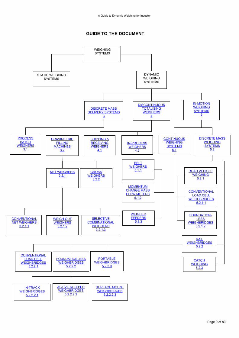
SCOPE OF DOCUMENT This Guide covers almost all types of weighing systems where it is considered that material being weighed is, or may be, in net motion relative to the weighing machine, and these are classified as dynamic weighing systems. Industry utilises a variety of dynamic weighing systems to suit the specific measurement requirement. One area which is not covered, but which is planned to be tackled in a future revision, is the specific case of catchweighers attached to moving parts of vehicles such as fork-lift trucks or refuse collection lorries. From a material handling viewpoint, most industrial processes involving weighing are designed to handle their raw material feedstock (such as powders, pellets, particulates, lumps, and liquids) in discrete quantities or batches, rather than being fed with a continuous stream. For example, a bakery process requires its flour to arrive in convenient quantities to handle. This may be in the form of bags or a road tanker, both arriving as a batch quantity. The outputs of most industrial manufacturing processes that involve weighing utilise the concept of process batch weighing, whereby the final product is produced in discrete, individually-prepared batches, and where at any given time the process is either preparing batches or delivering recently completed batches. Alternatively, some manufacturing processes are continuous, with weighed feeders continuously delivering materials into continuous production processes (including continuous mixers). It is often chosen to manufacture by a continuous process to increase efficiency, in other instances by a necessity of the manufacturing method (such as extruding). Dynamic weighing systems covered by this Guide are broadly divided into three categories according to the way they operate. These categories are shown in the block diagram entitled "Guide to the Document" given at the end of this section.
Discrete mass delivery weighing systems weigh defined masses of material into batches where each batch may be put into a container or may be combined with other weighed masses to make up a mixture against a formula. These weighing systems represent a large majority of the dynamic weighing applications and use diverse range of weighing machines. Examples of these are process batch weighers and gravimetric filling machines.
Discontinuous totalising weighing systems are those which totalise discrete batch weights for the purpose of recording the accumulated total weight of a larger bulk mass of material, and sometimes also the throughput. These are always single feeder weighers. Examples are shipping and receiving weighers and in-process weighers.
In-motion weighing systems are those, which determine the mass of moving objects or material passing over or through a device. The flow of measured mass may be continuous, as in the case of a stream of particulate material passing over a belt weigher, or it may comprise discrete weighing events as in the form of road vehicle or rolling stock axles or packages on a conveyor belt. Examples are belt weighers and catch weighers.
These categories are further sub-divided to cover applications where it is considered the weighing falls within the dynamic weighing category. There are, however, a number of applications where it may appear the weighing function is dynamic, such as weighing on board of aircraft or on board of road vehicles, or weighing of animals. These are considered to be fundamentally static weighing as there is no net motion relative to the weighing machine and they are therefore not included in this Guide. Each application is presented in a uniform way to cover the following subject areas:
Application Construction Typical performance Factors affecting accuracy Calibration/Verification
Page 7 of 83

A Guide to Dynamic Weighing for Industry
In the “Typical performance” sections, the weight range and accuracy figures stated are simply given as a guide to standard equipment regularly used in such applications – this is not to say that equipment is unavailable outside these weight ranges or that its performance may not be significantly better or worse than the values quoted. Calibration is simply the act of determining the accuracy of the indications of the instrument throughout its measuring range. It does not involve the adjustment of the instrument to improve the accuracy of the indications, although such adjustment may take place at the same time. The term Verification is used mainly in legal metrology - that is the use of weighing or measuring instruments for purposes which fall under the control of either national or European legislation relating to weighing or measuring for purposes of trade, law enforcement, and consumer protection. “Verification”, in legal metrology terms, is a specific act, carried out to determine that an instrument performs within the permitted error allowances throughout its measuring range and that it also conforms to all relevant Weights and Measures legislation. Verification can be carried out by: A Weights and Measures Inspector; an Authorised Person; an Accredited Person, Manufacturer or Installer. Once the instrument has been tested, examined, and found to meet all the legislative requirements it is usually marked in some way, either with a stamp or irremovable sticker, identifying the organisation or person that has verified the instrument. Verification is necessary before an instrument can be taken into use for a legally controlled purpose. “Authorised Person” is a term used specifically in the Non-automatic Weighing Instruments Regulations 2000 (SI 2000 No 3236). It means an inspector (of Weights and Measures) or some other person employed by a local weights and measures authority, who is authorised by the Chief Inspector of Weights and Measures of that authority to exercise functions under the regulations within the area of the local authority. Before these regulations were introduced, the enforcement and verification activities under previous regulations could only be exercised by an Inspector of Weights and Measures; these regulations allow for other persons, suitably trained, to carry out those functions. A selection of useful reading material is given in Section 6 Bibliography. Some of these may be given as a specific reference; in this case the reference number is given in the text in bold and in bold square brackets. Some of the dynamic weighing systems may be subject to legal metrological control. Where it is relevant, each section lists the appropriate informative references in the form of the European Measuring Instruments Directive (MID), International Organisation of Legal Metrology (OIML) Recommendations, and legal documentation. This Guide, however, should not be considered a complete source of regulations and further information should be sought from authoritative bodies such as National Metrological Institutes or Local Enforcement Offices.
Page 8 of 83
A Guide to Dynamic Weighing for Industry
GUIDE TO THE DOCUMENT
FOUNDATION-LESS
WEIGHBRIDGES5.2.1.2
CONVENTIONAL LOAD CELL
WEIGHBRIDGES5.2.1.1
SURFACE MOUNT WEIGHBRIDGES
5.2.2.2.3
ACTIVE SLEEPER WEIGHBRIDGES
5.2.2.2.2
IN-TRACK WEIGHBRIDGES
5.2.2.2.1
PORTABLE
WEIGHBRIDGES5.2.2.3
FOUNDATIONLESS
WEIGHBRIDGES 5.2.2.2
CONVENTIONAL LOAD CELL
WEIGHBRIDGES 5.2.2.1
CATCH WEIGHING
5.2.3
RAIL WEIGHBRIDGES
5.2.2
ROAD VEHICLE WEIGHING
5.2.1
WEIGHED FEEDERS
5.1.3
MOMENTUM CHANGE MASS FLOW METERS
5.1.2
BELT WEIGHERS
5.1.1
SELECTIVE COMBINATIONAL
WEIGHERS 3.2.1.3
WEIGH OUT WEIGHERS
3.2.1.2
CONVENTIONAL NET WEIGHERS
3.2.1.1
GROSS WEIGHERS
3.2.2
NET WEIGHERS 3.2.1
PROCESS BATCH
WEIGHERS 3.1
GRAVIMETRIC FILLING
MACHINES 3.2
DISCRETE MASS WEIGHING SYSTEMS
5.2
CONTINUOUS WEIGHING SYSTEMS
5.1
IN-PROCESS WEIGHERS
4.2
SHIPPING & RECEIVING WEIGHERS
4.1
IN-MOTION WEIGHING SYSTEMS
5
DISCONTINUOUS TOTALISING WEIGHERS
4
DISCRETE MASS
DELIVERY SYSTEMS3
DYNAMIC WEIGHING SYSTEMS
STATIC WEIGHING SYSTEMS
WEIGHING SYSTEMS
Page 9 of 83
A Guide to Dynamic Weighing for Industry
3.
• • • • • • • •
DISCRETE MASS DELIVERY SYSTEMS Discrete mass delivery systems cover a diverse range of weighing machines. What makes them unique is that they weigh defined masses of material into individual batches. Each batch may be either put into individual containers or combined with other weighed masses to make up a prepared formulation or batch mixture. Many dynamic weighing systems fall into this category from machines that prepare pre-packaged goods to pre-mixed materials for industrial batch processes. The weighed ingredients may be powders, granules, lumps, or liquids that are proportional by weight rather than volume. 3.1 Process Batch Weighers Many industrial processes are easier to operate if the materials are separated into discrete batches where the weights and mixing quality can be tightly controlled. The industries where batch weighing is most prevalent are as follows:
Animal Feed Food Chemical Mineral Fertilizer Rubber & Plastics Pharmaceutical Glass
They range from single weigh vessel systems often referred to as Cumulative Batching Systems where each ingredient is weighed sequentially and layered into the weigh hopper, to complex multiple weigh vessel systems also known as Simultaneous Batching Systems where ingredients are weighed simultaneously by separate vessels. This latter group encompasses a wide range of hybrids that weigh both simultaneously and sequentially. The vessels to be weighed are supported by load cells that are connected to a Batch Controller, which usually serves both to energise and condition the load cell signals as well as to perform the logic operations based on those signals and to provide outputs to other peripheral equipment and the operator. Systems often involve other process steps (such as heating or analytical control) interwoven into the overall control sequences, but for the purposes of this document the sequence actions considered are fundamentally related to weight measurement only and utilise dedicated batch weighing control instrumentation. The weighed vessels are basically static weighing devices that share the influences and considerations considered elsewhere (see section 6, WGC1099). The dynamic element in the measurement comes from the fact that the product being weighed is in motion before, possibly during, and after the measurement has taken place, and the effect of this motion is the focus of what follows in this section. The dynamic nature of the process leads to two main measurement and control issues that require consideration. When a material is being added to or removed from a vessel there is a delay in response between the observation that the required target weight has been reached and the termination of the addition. This delay or ‘in-flight’ time is a function of the overall measurement and control loop delays as well as the physical arrangement of the system. There will be additional material added (or removed) during this delay, and this will introduce an error that all batch weighing systems attempt to regulate and minimise. There is an additional measurement error caused by the change in momentum of the flowing material as it enters or leaves the weighed vessel and again batching systems need to account for this effect (see section 6, WGC1099).
Page 10 of 83
A Guide to Dynamic Weighing for Industry
3.1.1 Application Dedicated process batch weighing systems are beneficially used in applications where the manufacturing process is fundamentally centred on weight measurement coupled with the control of the plant sequences up and down stream of the weighing measurement, but with limited other process measurement or control requirements. In these applications the speed and expert knowledge facilities built into a dedicated system can bring technical advantages at a lower cost than that offered by more general process control solutions. Process batch weighing systems can have almost infinite configuration possibilities but, for the purposes of illustration in this document, fall into two broad categories of cumulative batching and simultaneous batching which may be combined and usefully referred to as combination batching.
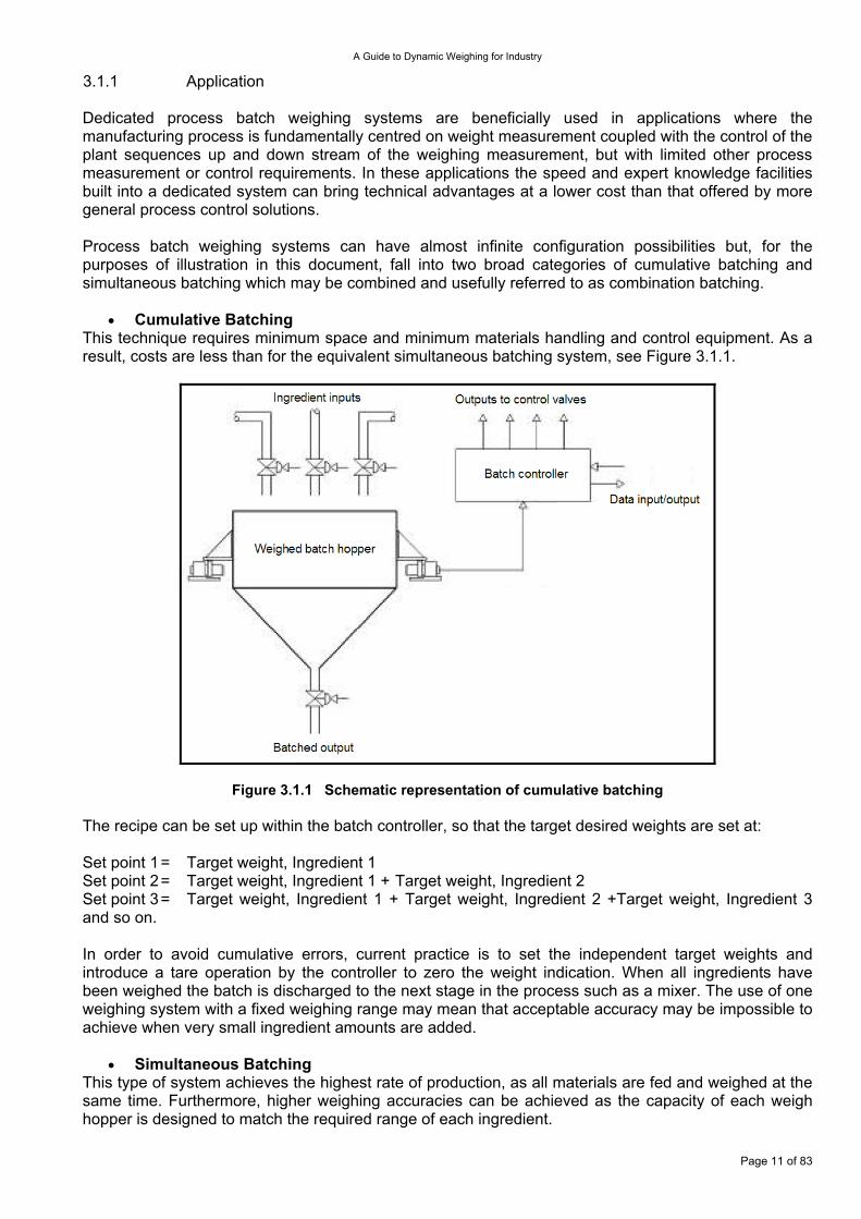
Cumulative Batching • This technique requires minimum space and minimum materials handling and control equipment. As a result, costs are less than for the equivalent simultaneous batching system, see Figure 3.1.1.
Figure 3.1.1 Schematic representation of cumulative batching
The recipe can be set up within the batch controller, so that the target desired weights are set at: Set point 1 = Target weight, Ingredient 1 Set point 2 = Target weight, Ingredient 1 + Target weight, Ingredient 2 Set point 3 = Target weight, Ingredient 1 + Target weight, Ingredient 2 +Target weight, Ingredient 3 and so on. In order to avoid cumulative errors, current practice is to set the independent target weights and introduce a tare operation by the controller to zero the weight indication. When all ingredients have been weighed the batch is discharged to the next stage in the process such as a mixer. The use of one weighing system with a fixed weighing range may mean that acceptable accuracy may be impossible to achieve when very small ingredient amounts are added.
Simultaneous Batching • This type of system achieves the highest rate of production, as all materials are fed and weighed at the same time. Furthermore, higher weighing accuracies can be achieved as the capacity of each weigh hopper is designed to match the required range of each ingredient.
Page 11 of 83
A Guide to Dynamic Weighing for Industry
In operation, the control set points are set up for each ingredient. After the material has settled, the tolerances are checked automatically and materials are discharged in a predetermined sequence. The Simultaneous Batching technique also facilitates pre-blending of materials during the discharge phase, if required. For example, solid materials may be discharged onto a moving conveyor. The material from one weigher is discharged to the conveyor. When this material reaches the second weigher the material weighed on this scale commences discharge, layering the second material on the top of the first material and so on until the total batch is complete. When the ingredients in all the weigh hoppers have been discharged, the control system initiates a zero tolerance check on all weighers; if this is satisfactory the batch is discharged to the next stage in the process and the system is ready to produce another batch.
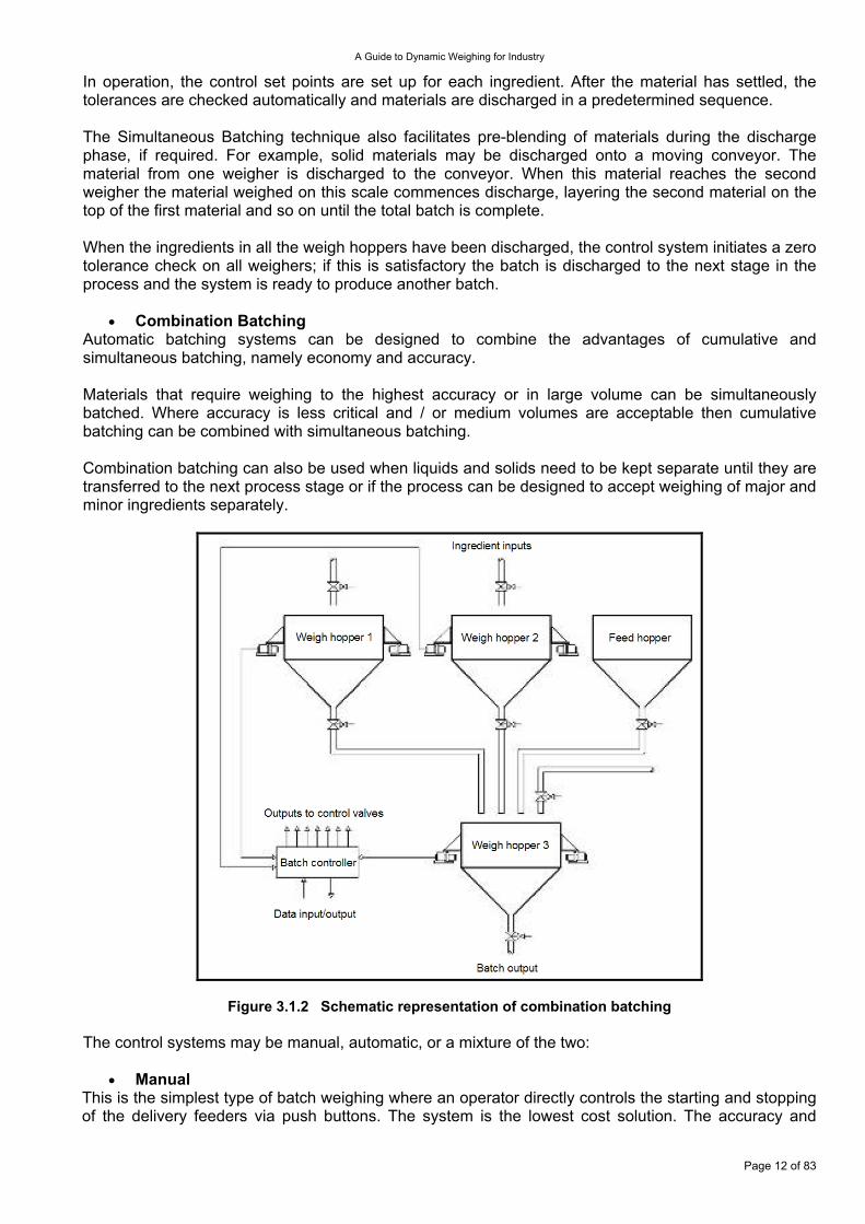
Combination Batching • Automatic batching systems can be designed to combine the advantages of cumulative and simultaneous batching, namely economy and accuracy. Materials that require weighing to the highest accuracy or in large volume can be simultaneously batched. Where accuracy is less critical and / or medium volumes are acceptable then cumulative batching can be combined with simultaneous batching. Combination batching can also be used when liquids and solids need to be kept separate until they are transferred to the next process stage or if the process can be designed to accept weighing of major and minor ingredients separately.
Figure 3.1.2 Schematic representation of combination batching The control systems may be manual, automatic, or a mixture of the two:
Manual • This is the simplest type of batch weighing where an operator directly controls the starting and stopping of the delivery feeders via push buttons. The system is the lowest cost solution. The accuracy and
Page 12 of 83
A Guide to Dynamic Weighing for Industry
sequence of batching is totally in the hands of the operator and the process complexity and speed will need to take account of human factors. The operation is often monitored by logging the batch data.
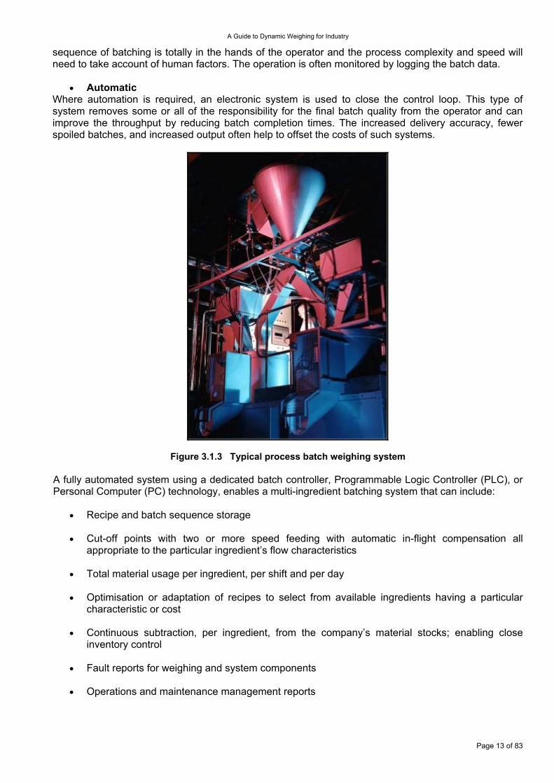
Automatic • Where automation is required, an electronic system is used to close the control loop. This type of system removes some or all of the responsibility for the final batch quality from the operator and can improve the throughput by reducing batch completion times. The increased delivery accuracy, fewer spoiled batches, and increased output often help to offset the costs of such systems.
Figure 3.1.3 Typical process batch weighing system A fully automated system using a dedicated batch controller, Programmable Logic Controller (PLC), or Personal Computer (PC) technology, enables a multi-ingredient batching system that can include:
Recipe and batch sequence storage •
•
•
•
•
•
•
Cut-off points with two or more speed feeding with automatic in-flight compensation all appropriate to the particular ingredient’s flow characteristics
Total material usage per ingredient, per shift and per day
Optimisation or adaptation of recipes to select from available ingredients having a particular characteristic or cost
Continuous subtraction, per ingredient, from the company’s material stocks; enabling close inventory control
Fault reports for weighing and system components
Operations and maintenance management reports
Page 13 of 83
A Guide to Dynamic Weighing for Industry
3.1.2 Construction The construction of the weighing equipment should meet all the criteria necessary for a static weigh hopper installation (see section 6, WGC1099). Additionally the best practice for the design, manufacture, and installation of the materials handling equipment should be implemented; material handling errors can be significantly greater than static weighing errors. From the weighing measurement and control viewpoint, the layout and construction should be such as to reduce the magnitude and variability of the two dynamic errors; in-flight material and momentum change. The range of possible actions to achieve this will clearly be dependant on the physical layout of the plant and the nature of the process. For example, liquid control valves should be located at the end of feed pipes, solids feeders may require special designs involving special delivery mechanisms, outlets, or closure gates to increase the repeatability of the final cut off, and the effect of product impact may be reduced by deflecting the material flow on entry away from the weighing axis. The variability of in-flight material and momentum change can clearly be reduced by lowering the feed rate at the expense of batch cycle time. A compromise that is often used is to introduce more than one feed rate and to use the reduced rate or rates only at the final stages of the feed. 3.1.3 Typical Performance A static weighing system may have its accuracy performance expressed in terms of simple numerical errors, the error being the difference between the weight value as output by the weighing system and the conventional true value of that weight. A full presentation of static system error parameters is given elsewhere (see section 6, WGC1099). Defining accuracy parameters for a batch weighing system is made more complicated because of the dynamic nature of the weighing process. For example; if a machine is set to discharge a large number of batches of a fixed weight (say 20 kg), the values of the resulting batch weights will not all be the same. None of them will be exactly 20 kg (although the difference from 20 kg may not be measurable). Instead, the weight values will fall within a certain range, from the minimum value up to the maximum value.
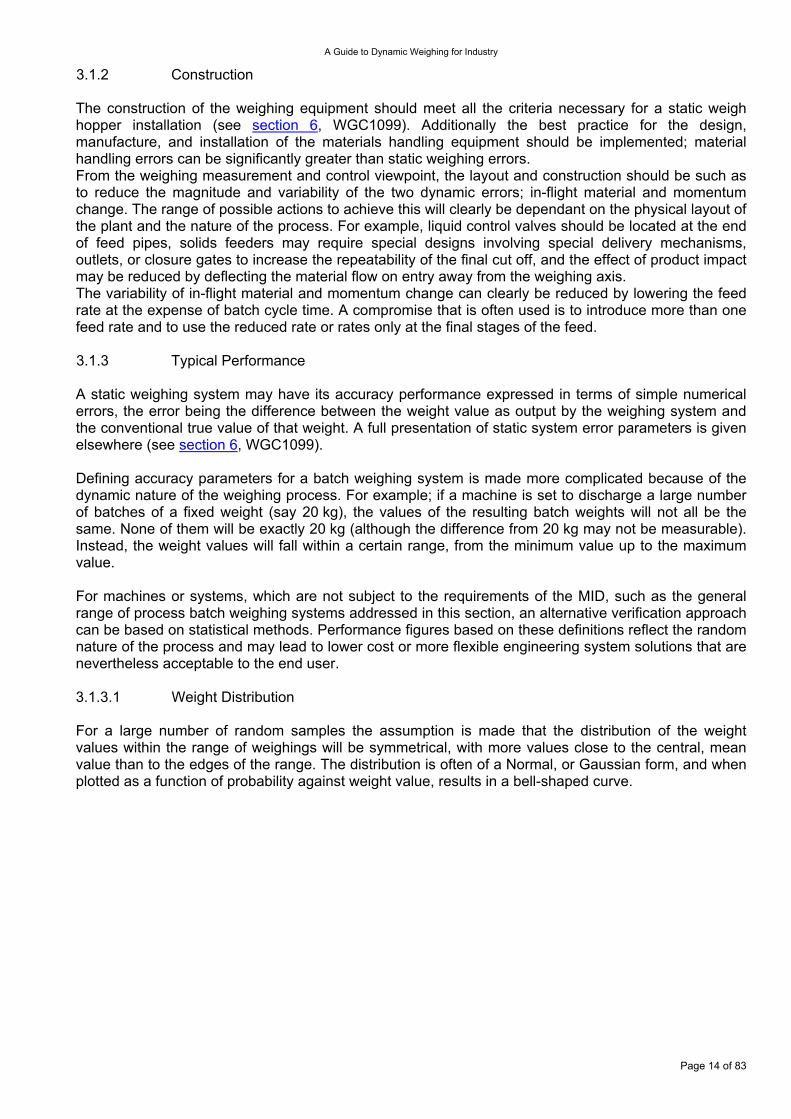
For machines or systems, which are not subject to the requirements of the MID, such as the general range of process batch weighing systems addressed in this section, an alternative verification approach can be based on statistical methods. Performance figures based on these definitions reflect the random nature of the process and may lead to lower cost or more flexible engineering system solutions that are nevertheless acceptable to the end user. 3.1.3.1 Weight Distribution For a large number of random samples the assumption is made that the distribution of the weight values within the range of weighings will be symmetrical, with more values close to the central, mean value than to the edges of the range. The distribution is often of a Normal, or Gaussian form, and when plotted as a function of probability against weight value, results in a bell-shaped curve.
Page 14 of 83
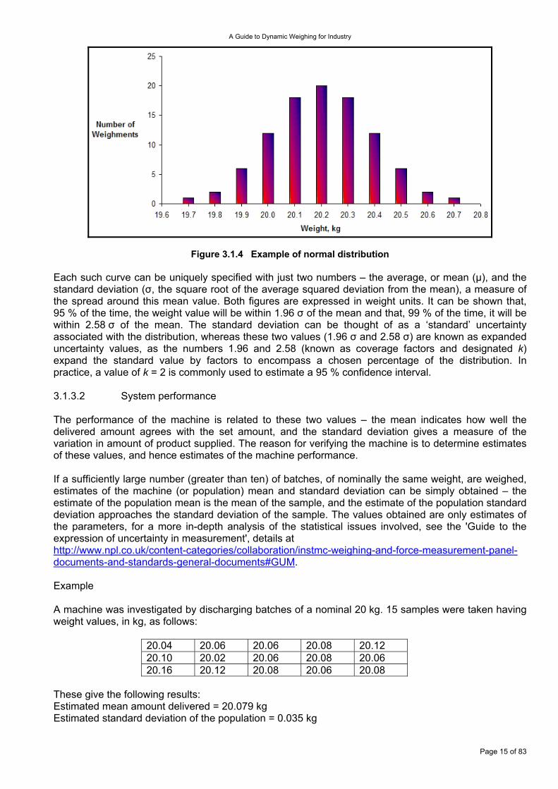
A Guide to Dynamic Weighing for Industry
Figure 3.1.4 Example of normal distribution Each such curve can be uniquely specified with just two numbers – the average, or mean (µ), and the standard deviation (σ, the square root of the average squared deviation from the mean), a measure of the spread around this mean value. Both figures are expressed in weight units. It can be shown that, 95 % of the time, the weight value will be within 1.96 σ of the mean and that, 99 % of the time, it will be within 2.58 σ of the mean. The standard deviation can be thought of as a ‘standard’ uncertainty associated with the distribution, whereas these two values (1.96 σ and 2.58 σ) are known as expanded uncertainty values, as the numbers 1.96 and 2.58 (known as coverage factors and designated k) expand the standard value by factors to encompass a chosen percentage of the distribution. In practice, a value of k = 2 is commonly used to estimate a 95 % confidence interval. 3.1.3.2 System performance The performance of the machine is related to these two values – the mean indicates how well the delivered amount agrees with the set amount, and the standard deviation gives a measure of the variation in amount of product supplied. The reason for verifying the machine is to determine estimates of these values, and hence estimates of the machine performance. If a sufficiently large number (greater than ten) of batches, of nominally the same weight, are weighed, estimates of the machine (or population) mean and standard deviation can be simply obtained – the estimate of the population mean is the mean of the sample, and the estimate of the population standard deviation approaches the standard deviation of the sample. The values obtained are only estimates of the parameters, for a more in-depth analysis of the statistical issues involved, see the 'Guide to the expression of uncertainty in measurement', details at http://www.npl.co.uk/content-categories/collaboration/instmc-weighing-and-force-measurement-panel-documents-and-standards-general-documents#GUM. Example A machine was investigated by discharging batches of a nominal 20 kg. 15 samples were taken having weight values, in kg, as follows:
20.04 20.06 20.06 20.08 20.12 20.10 20.02 20.06 20.08 20.06 20.16 20.12 20.08 20.06 20.08
These give the following results: Estimated mean amount delivered = 20.079 kg Estimated standard deviation of the population = 0.035 kg
Page 15 of 83
A Guide to Dynamic Weighing for Industry
Note that this standard deviation relates solely to the repeatability of the batch weights, and does not take into account the uncertainty of the apparatus used to measure the resulting weights, including its resolution. In practice, this contribution would need to be combined with the repeatability component, to give an overall system uncertainty. When combining uncertainty contributions from different (or independent, or uncorrelated) sources, they should be added in quadrature (rather than linearly). This means that the resulting uncertainty is the square root of the sum of the squares of the individual uncertainty contributions. For example, four uncorrelated contributions, each of 0.1 kg, would give a combined uncertainty of 0.2 kg (rather than the 0.4 kg value given by a linear combination). This follows from the fact that it is unlikely that all four uncertainty components will affect the final result in the same direction (i.e. all increase it or all reduce it). If the apparatus calibration certificate quoted an uncertainty of ± 0.040 kg, at a 95 % confidence level (i.e. k = 2), its standard uncertainty of 0.020 kg (0.040 / k) should be combined in quadrature with the repeatability component (0.035 kg) to give a combined standard uncertainty of 0.040 kg and an expanded uncertainty of 0.081 kg. The results of the investigation could then be stated as follows: “When set to deliver a nominal 20 kg, the actual amount delivered by the machine was 20.08 kg ± 0.08 kg, at a 95 % level of confidence.” This is another way of saying that, 95 % of the time; the amount delivered would lie in the range from 20.00 kg to 20.16 kg. The maximum deviation from the set amount is 0.16 kg so, for customers who require an accuracy figure relating to the nominal amount, it would also be true to state that: “When set to deliver a nominal 20 kg, the actual amount delivered by the machine was correct to within 0.16 kg, or 0.80 %, at a 95 % level of confidence.” The required accuracy of a batch weighing system requires both technical and realistic consideration. Bearing in mind the foregoing it would be possible to exercise such a level of control on a weight addition that the batch weighing error approaches the best achievable incremental static weighing error. For a strain gauge load cell based industrial system this could be ±0.01 % of full weigh scale range. The demands that this target places on the installation mechanics and the restrictions incurred to the batch cycle times will mean that the typical performance will be worse than this. A guide to what might realistically be expected can be inferred from OIML R 61 in which the tightest regulation requires batch-filling errors to be of the order of ±0.1 % to ±0.2 % of the added weight. Where a batch comprises ingredients added cumulatively to just one vessel the conventional combined error of the weighments becomes secondary to the repeatability and linearity of the weight measurement system, since it is the ratio of the various ingredients to the total batch size that is likely to be critical rather than the absolute weight of any of the ingredients. In these cases the demanded weighing performance criteria could be more exacting than the ±0.1 % to ±0.2 % of the added weight suggested above. 3.1.4 Factors Affecting Accuracy The principal dynamic influence factors are listed below (where particular applications have specific factors these will be listed in the appropriate sub-section):
High Feed Rate •
The force set up by momentum changes due to the impact of the material flow can cause the trip point to be triggered prematurely. The errors can be reduced by reducing the feed rate, often achieved by retaining high feed rate coarse segments of the weighing cycle to minimise the cycle time, but introducing one or more fine feed segments with lower feed rates. Additionally the physical
Page 16 of 83
A Guide to Dynamic Weighing for Industry
layout of the inlet ducts may be engineered to minimise the effect impact forces on the weight measurement. In some applications the presence of a high initial impact force may be overcome by incorporating a time delay into the control cycle to allow the system to ignore it until it dies away.
Delayed Cut-Off Response •
•
•
This effect is characterised by a compensation weight that decreases the feeder cut-off point to allow for the material that is still falling.
Inconsistent Material Flow
This occurs when the material stream flow rate varies such as when the rate pulses because of the design of the screw feeder, if there is partial starvation due to material bridging in the hopper or other material handling issues. Compensation will not easily correct this problem although there is the possibility to add instantaneous feed rate corrections into the in-flight compensation. The solution usually lies in properly designing the hoppers, ensuring a constant minimum head of material and if necessary material flow enhancers.
Miscellaneous Factors
There are a number of variables in an automatic weighing operation, which can vary from one weighing cycle to the next - these include: variation in the speed of operation of the cut off mechanisms; material density variation; and vibrations transmitted through the support structure or originating from the vibro-feeders or other motorised equipment mounted on the weighed structure itself.
3.1.5 Calibration/Verification The first stage in calibration is similar to that used for static weigh hopper systems. The static calibration does not address the dynamic variables such as material characteristics, cut-off response, and the characteristics of the materials handling equipment. In practice a series of consecutive test weighings are recorded after all initial adjustments, including the appropriate feed rates and in-flight compensation, have been correctly applied to the system. From these results, the degree of compliance with the design specification may be determined. 3.2 Gravimetric Filling Machines These machines are designed to fill one or more types of the containers such as bags, drums, and Semi Bulk Containers (SBC). They are always single feeder, single material weighing systems. They automatically fill containers with a predetermined and virtually constant weight of product from bulk using a controller which is usually based on a computer. The machines are generally required to comply with the MID. 3.2.1 Net Weighers These machines fill containers with a predetermined weight of product. They weigh powder, particulates, or lumps of material into or out of a weigh vessel to a pre-set value, prior to filling transport containers such as bags, drums, SBCs. They are termed net weighers because only the material is weighed in a weigh vessel (or multiple weigh vessels), before being discharged into a container. The equipment comprises a material feeding mechanism and a weigh vessel.
Page 17 of 83
A Guide to Dynamic Weighing for Industry
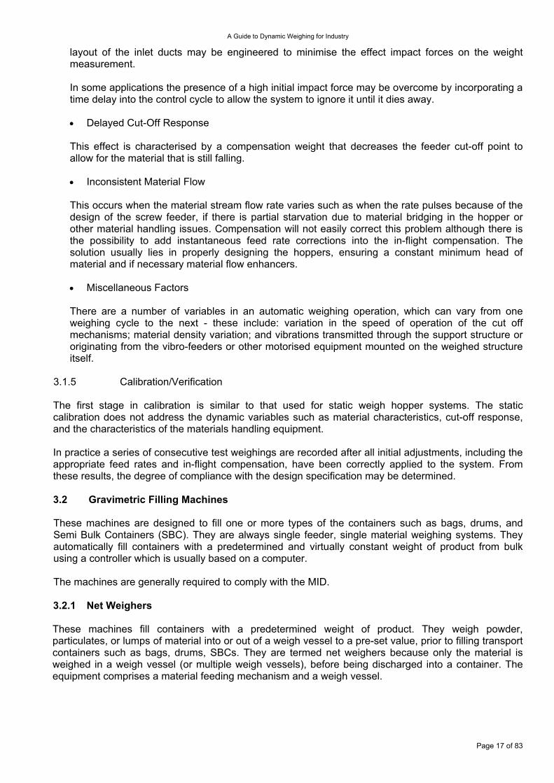
Figure 3.2.1.1 50 kg net weigher with integral feed gate, pneumatics, and electrics The up-stream plant is a silo, day bin, or receiving hopper and the down-stream equipment is a container filling mechanism, which in the majority of cases will be a discharge chute and bag spout, with a bag clamp. In some applications the container may take more than one discharge to be filled. These machines are known as cumulative weighers. Net weighers have an advantage of increased speed of operation over gross weighers, because they do not have to wait for a container to be in position before starting the weigh cycle. 3.2.1.1 Conventional Net Weighers These machines comprise a material feeding mechanism that feeds material into a weigh vessel to a pre-set weight. They are by far the most common application of net weighers. 3.2.1.1.1 Application The weigher is used in a wide range of applications - however, the selection feeder type depends upon the material being delivered.
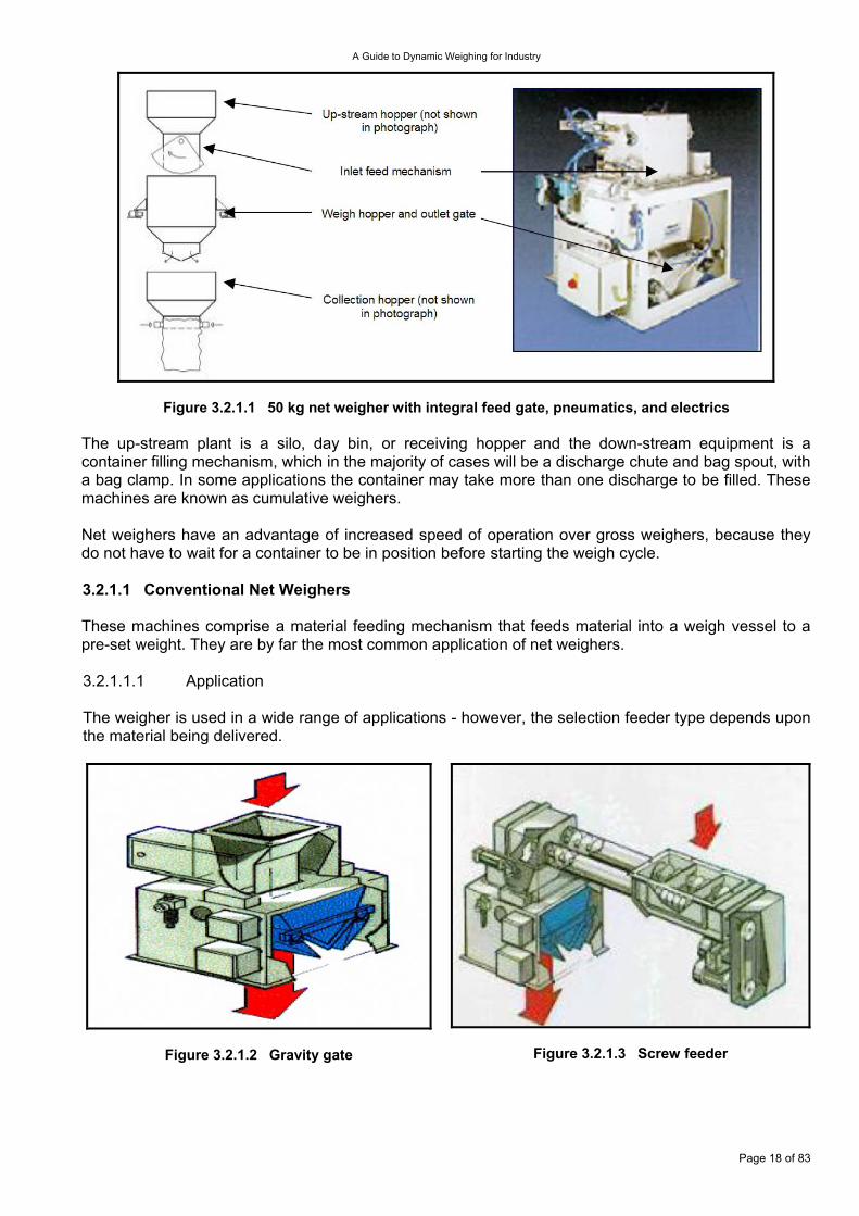
Figure 3.2.1.2 Gravity gate
Figure 3.2.1.3 Screw feeder
Page 18 of 83
A Guide to Dynamic Weighing for Industry
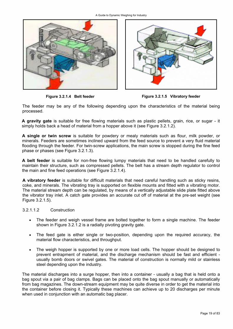
Figure 3.2.1.4 Belt feeder
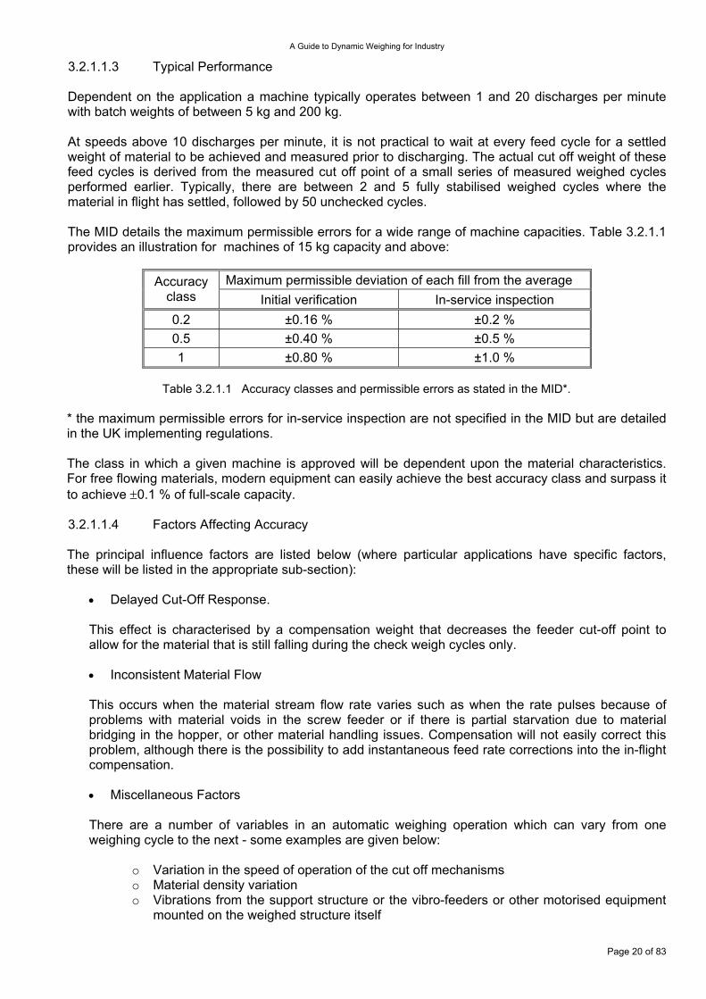
Figure 3.2.1.5 Vibratory feeder
The feeder may be any of the following depending upon the characteristics of the material being processed.
A gravity gate is suitable for free flowing materials such as plastic pellets, grain, rice, or sugar - it simply holds back a head of material from a hopper above it (see Figure 3.2.1.2).
A single or twin screw is suitable for powdery or mealy materials such as flour, milk powder, or minerals. Feeders are sometimes inclined upward from the feed source to prevent a very fluid material flooding through the feeder. For twin-screw applications, the main screw is stopped during the fine feed phase or phases (see Figure 3.2.1.3). A belt feeder is suitable for non-free flowing lumpy materials that need to be handled carefully to maintain their structure, such as compressed pellets. The belt has a stream depth regulator to control the main and fine feed operations (see Figure 3.2.1.4). A vibratory feeder is suitable for difficult materials that need careful handling such as sticky resins, coke, and minerals. The vibrating tray is supported on flexible mounts and fitted with a vibrating motor. The material stream depth can be regulated, by means of a vertically adjustable slide plate fitted above the vibrator tray inlet. A catch gate provides an accurate cut off of material at the pre-set weight (see Figure 3.2.1.5). 3.2.1.1.2 Construction
The feeder and weigh vessel frame are bolted together to form a single machine. The feeder shown in Figure 3.2.1.2 is a radially pivoting gravity gate.
•
•
•
The feed gate is either single or two-position, depending upon the required accuracy, the material flow characteristics, and throughput.
The weigh hopper is supported by one or more load cells. The hopper should be designed to prevent entrapment of material, and the discharge mechanism should be fast and efficient - usually bomb doors or swivel gates. The material of construction is normally mild or stainless steel depending upon the industry.
The material discharges into a surge hopper, then into a container - usually a bag that is held onto a bag spout via a pair of bag clamps. Bags can be placed onto the bag spout manually or automatically from bag magazines. The down-stream equipment may be quite diverse in order to get the material into the container before closing it. Typically these machines can achieve up to 20 discharges per minute when used in conjunction with an automatic bag placer.
Page 19 of 83
A Guide to Dynamic Weighing for Industry
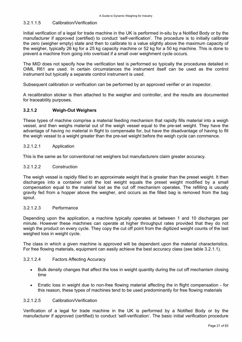
3.2.1.1.3 Typical Performance Dependent on the application a machine typically operates between 1 and 20 discharges per minute with batch weights of between 5 kg and 200 kg. At speeds above 10 discharges per minute, it is not practical to wait at every feed cycle for a settled weight of material to be achieved and measured prior to discharging. The actual cut off weight of these feed cycles is derived from the measured cut off point of a small series of measured weighed cycles performed earlier. Typically, there are between 2 and 5 fully stabilised weighed cycles where the material in flight has settled, followed by 50 unchecked cycles. The MID details the maximum permissible errors for a wide range of machine capacities. Table 3.2.1.1 provides an illustration for machines of 15 kg capacity and above:
Maximum permissible deviation of each fill from the average Accuracy
class Initial verification In-service inspection 0.2 ±0.16 % ±0.2 % 0.5 ±0.40 % ±0.5 % 1 ±0.80 % ±1.0 %
Table 3.2.1.1 Accuracy classes and permissible errors as stated in the MID*.
* the maximum permissible errors for in-service inspection are not specified in the MID but are detailed in the UK implementing regulations. The class in which a given machine is approved will be dependent upon the material characteristics. For free flowing materials, modern equipment can easily achieve the best accuracy class and surpass it to achieve ±0.1 % of full-scale capacity. 3.2.1.1.4 Factors Affecting Accuracy The principal influence factors are listed below (where particular applications have specific factors, these will be listed in the appropriate sub-section):
Delayed Cut-Off Response. •
•
•
This effect is characterised by a compensation weight that decreases the feeder cut-off point to allow for the material that is still falling during the check weigh cycles only.
Inconsistent Material Flow
This occurs when the material stream flow rate varies such as when the rate pulses because of problems with material voids in the screw feeder or if there is partial starvation due to material bridging in the hopper, or other material handling issues. Compensation will not easily correct this problem, although there is the possibility to add instantaneous feed rate corrections into the in-flight compensation.
Miscellaneous Factors
There are a number of variables in an automatic weighing operation which can vary from one weighing cycle to the next - some examples are given below:
o Variation in the speed of operation of the cut off mechanisms o Material density variation o Vibrations from the support structure or the vibro-feeders or other motorised equipment
mounted on the weighed structure itself
Page 20 of 83
A Guide to Dynamic Weighing for Industry
3.2.1.1.5 Calibration/Verification Initial verification of a legal for trade machine in the UK is performed in-situ by a Notified Body or by the manufacturer if approved (certified) to conduct ‘self-verification’. The procedure is to initially calibrate the zero (weigher empty) state and then to calibrate to a value slightly above the maximum capacity of the weigher, typically 26 kg for a 25 kg capacity machine or 52 kg for a 50 kg machine. This is done to prevent a machine from going into overload if a small over weighment cycle occurs. The MID does not specify how the verification test is performed so typically the procedures detailed in OIML R61 are used. In certain circumstances the instrument itself can be used as the control instrument but typically a separate control instrument is used. Subsequent calibration or verification can be performed by an approved verifier or an inspector. A recalibration sticker is then attached to the weigher and controller, and the results are documented for traceability purposes. 3.2.1.2 Weigh-Out Weighers These types of machine comprise a material feeding mechanism that rapidly fills material into a weigh vessel, and then weighs material out of the weigh vessel equal to the pre-set weight. They have the advantage of having no material in flight to compensate for, but have the disadvantage of having to fill the weigh vessel to a weight greater than the pre-set weight before the weigh cycle can commence. 3.2.1.2.1 Application This is the same as for conventional net weighers but manufacturers claim greater accuracy. 3.2.1.2.2 Construction The weigh vessel is rapidly filled to an approximate weight that is greater than the preset weight. It then discharges into a container until the lost weight equals the preset weight modified by a small compensation equal to the material lost as the cut off mechanism operates. The refilling is usually gravity fed from a hopper above the weigher, and occurs as the filled bag is removed from the bag spout. 3.2.1.2.3 Performance Depending upon the application, a machine typically operates at between 1 and 10 discharges per minute. However these machines can operate at higher throughput rates provided that they do not weigh the product on every cycle. They copy the cut off point from the digitized weight counts of the last weighed loss in weight cycle. The class in which a given machine is approved will be dependent upon the material characteristics. For free flowing materials, equipment can easily achieve the best accuracy class (see table 3.2.1.1). 3.2.1.2.4 Factors Affecting Accuracy
Bulk density changes that affect the loss in weight quantity during the cut off mechanism closing time
•
•
Erratic loss in weight due to non-free flowing material affecting the in flight compensation - for this reason, these types of machines tend to be used predominantly for free flowing materials
3.2.1.2.5 Calibration/Verification Verification of a legal for trade machine in the UK is performed by a Notified Body or by the manufacturer if approved (certified) to conduct ‘self-verification’. The basic initial verification procedure
Page 21 of 83
A Guide to Dynamic Weighing for Industry
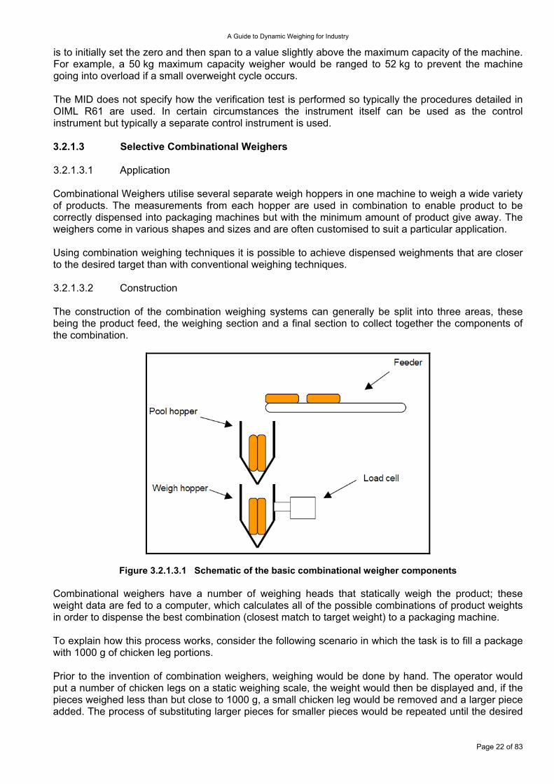
is to initially set the zero and then span to a value slightly above the maximum capacity of the machine. For example, a 50 kg maximum capacity weigher would be ranged to 52 kg to prevent the machine going into overload if a small overweight cycle occurs. The MID does not specify how the verification test is performed so typically the procedures detailed in OIML R61 are used. In certain circumstances the instrument itself can be used as the control instrument but typically a separate control instrument is used. 3.2.1.3 Selective Combinational Weighers 3.2.1.3.1 Application Combinational Weighers utilise several separate weigh hoppers in one machine to weigh a wide variety of products. The measurements from each hopper are used in combination to enable product to be correctly dispensed into packaging machines but with the minimum amount of product give away. The weighers come in various shapes and sizes and are often customised to suit a particular application. Using combination weighing techniques it is possible to achieve dispensed weighments that are closer to the desired target than with conventional weighing techniques. 3.2.1.3.2 Construction The construction of the combination weighing systems can generally be split into three areas, these being the product feed, the weighing section and a final section to collect together the components of the combination.
Figure 3.2.1.3.1 Schematic of the basic combinational weigher components Combinational weighers have a number of weighing heads that statically weigh the product; these weight data are fed to a computer, which calculates all of the possible combinations of product weights in order to dispense the best combination (closest match to target weight) to a packaging machine. To explain how this process works, consider the following scenario in which the task is to fill a package with 1000 g of chicken leg portions. Prior to the invention of combination weighers, weighing would be done by hand. The operator would put a number of chicken legs on a static weighing scale, the weight would then be displayed and, if the pieces weighed less than but close to 1000 g, a small chicken leg would be removed and a larger piece added. The process of substituting larger pieces for smaller pieces would be repeated until the desired
Page 22 of 83
A Guide to Dynamic Weighing for Industry
weight was achieved, and this product would then be placed in the final pack. This is clearly a labour intensive and slow procedure. The simplest form of combinational weigher that could be used to improve the efficiency of this task utilises a number of weighing heads. The operator places one piece of product on to each static scale, the data from these scales is then fed into a computer where the best combination of weights is found. A display would indicate which product / scales made up the weight - this product would be removed and placed in the final package and fresh product placed on the empty scales. Combinational weighers using static scales are available, but they are very labour intensive.
Figure 3.2.1.3.2 Illustration of a radial multi-head weigher
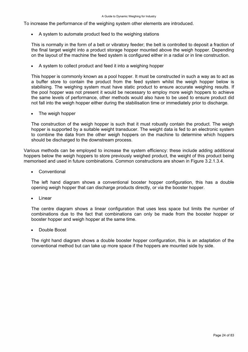
Figure 3.2.1.3.3 Illustration of a linear multi-head weigher with hand feed
Page 23 of 83
A Guide to Dynamic Weighing for Industry
To increase the performance of the weighing system other elements are introduced.
A system to automate product feed to the weighing stations •
•
•
•
•
•
This is normally in the form of a belt or vibratory feeder; the belt is controlled to deposit a fraction of the final target weight into a product storage hopper mounted above the weigh hopper. Depending on the layout of the machine the feed system is configured either in a radial or in line construction.
A system to collect product and feed it into a weighing hopper
This hopper is commonly known as a pool hopper. It must be constructed in such a way as to act as a buffer store to contain the product from the feed system whilst the weigh hopper below is stabilising. The weighing system must have static product to ensure accurate weighing results. If the pool hopper was not present it would be necessary to employ more weigh hoppers to achieve the same levels of performance, other methods would also have to be used to ensure product did not fall into the weigh hopper either during the stabilisation time or immediately prior to discharge.
The weigh hopper
The construction of the weigh hopper is such that it must robustly contain the product. The weigh hopper is supported by a suitable weight transducer. The weight data is fed to an electronic system to combine the data from the other weigh hoppers on the machine to determine which hoppers should be discharged to the downstream process.
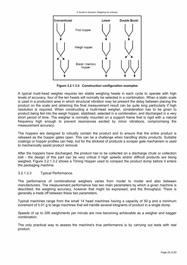
Various methods can be employed to increase the system efficiency: these include adding additional hoppers below the weigh hoppers to store previously weighed product, the weight of this product being memorised and used in future combinations. Common constructions are shown in Figure 3.2.1.3.4.
Conventional
The left hand diagram shows a conventional booster hopper configuration, this has a double opening weigh hopper that can discharge products directly, or via the booster hopper.
Linear
The centre diagram shows a linear configuration that uses less space but limits the number of combinations due to the fact that combinations can only be made from the booster hopper or booster hopper and weigh hopper at the same time.
Double Boost
The right hand diagram shows a double booster hopper configuration, this is an adaptation of the conventional method but can take up more space if the hoppers are mounted side by side.
Page 24 of 83
A Guide to Dynamic Weighing for Industry
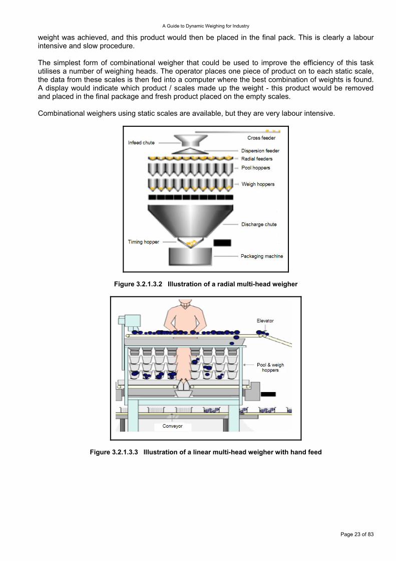
Figure 3.2.1.3.4 Construction configuration examples A typical multi-head weigher requires ten stable weighing heads in each cycle to operate with high levels of accuracy, four of the ten heads will normally be selected in a combination. When a static scale is used in a production area in which structural vibration may be present the delay between placing the product on the scale and obtaining the final measurement result can be quite long particularly if high resolution is required. When constructing a multi-head weigher, consideration has to be given to product being fed into the weigh hopper, stabilised, selected in a combination, and discharged in a very short period of time. The weigher is normally mounted on a support frame that is rigid with a natural frequency high enough to prevent resonances excited by minor vibrations, compromising the measurement accuracy. The hoppers are designed to robustly contain the product and to ensure that the entire product is released as the hopper gates open. This can be a challenge when handling sticky products. Suitable coatings or hopper profiles can help, but for the stickiest of products a scraper gate mechanism is used to mechanically assist product removal. After the hoppers have discharged, the product has to be collected on a discharge chute or collection belt - the design of this part can be very critical if high speeds and/or difficult products are being weighed. Figure 3.2.1.3.2 shows a Timing Hopper used to compact the product dump before it enters the packaging machine. 3.2.1.3.3 Typical Performance. The performance of combinational weighers varies from model to model and also between manufacturers. The measurement performance has two main parameters by which a given machine is described; the weighing accuracy, however that might be expressed, and the throughput. There is generally a trade off between these two parameters. Typical machines range from the small 14 head machines having a capacity of 50 g and a minimum increment of 0.01 g to large machines that will handle several kilograms of product in a single dump. Speeds of up to 200 weighments per minute are now becoming achievable as a weigher and bagger combination. The only practical way to assess the machine's true performance is by carrying out tests with real product.
Page 25 of 83
A Guide to Dynamic Weighing for Industry
3.2.1.3.4 Factors affecting Performance
Vibration •
•
•
Vibration, particularly at relatively low frequencies, transmitted through the support structure will affect the weighing speed and/or accuracy. The electronic filters required to reduce the effects of vibration will result in extended product settling times and fewer heads in the combination, resulting in reduced accuracy. Early designs of anti floor vibration systems increased the speed that a single medium size hopper could stabilize from 60 to 80 weighments per minute. However, it is possible to use methods to reduce settling times when moderate levels of vibration are present. One manufacturer, for example, uses a system to monitor floor vibration and make adjustments to the load cell outputs; this enables faster filtering and results in higher weighing speeds with more heads in the combination. This system uses four additional load cells mounted at the corners of the machine acting as vibration sensors. Data from these load cells is electronically processed and a signal is generated that is unique to each weighing head. This signal is mixed in anti phase to the measuring load cell output thus virtually eliminating the effects of the vibration.
Double phasing
Double phasing is a technique used to improve throughput. To illustrate this, consider a 14 head machine operating at 120 weighments per minute (WPM). The physical limit on each head is 60 WPM; the method used eliminates the four heads that have just discharged from the next weighing cycle. A combination is then made from four of the 10 stable heads; this leaves six unused weights for the next combination. The hoppers that discharged two cycles before are then used with the six heads from the previous cycle, thus the machine will have 10 stable heads available for a combination weighment. If a single head is capable of weighing at 100 WPM the maximum speed with double phasing will be 200 WPM. Care has to be taken when choosing a multihead weigher for high speed applications; most weighers indicate the stable heads and selected heads on the operator display from which careful observation will show if the weigher is double or even triple phasing. If a 14 head machine is triple phasing there could be 8 of the 14 heads that are not stable, this results in reduced number of combinations, which will ultimately affect accuracy.
Count priority software
Although a combinational weighing machine is used predominantly for producing a defined combination weight, the measurement calculations can be made and displayed in numbers of pieces. However the total pack weight is also checked before it discharges and could be rejected if it falls outside the set weight limits. The combination weigher can improve the weight count relationship and give better results than weighing the whole batch in one go. The improvements are made because the total discharge is split into approximately four parts.
For example: the objective is to weigh and dispatch 10 biscuits where the piece weight is 10 g ± 1 g. The weight for 10 biscuits in the worst cases can be 10 x 11g =110 g or 10 x 9 g = 90 g. This gives an error range of 20 g or two biscuits.
The combination weigher is set up to feed each weigh head with say 25 % of the target weight, in the worse practical case with poor adjustment this might be 30 % of the target weight.
This means that a maximum of 3 biscuits are being weighed rather than 10.
Page 26 of 83
A Guide to Dynamic Weighing for Industry
The errors in this measurement could be between 3 x 11 g = 33 g and 3 x 9 g = 27 g which is less than one piece of product, this facilitates an accurate determination of the number of biscuits in each hopper and results in the correct combination of hopper discharges to achieve the final target of 10.
Parent and Child •
•
Parent and Child software specifies that one hopper is dedicated to a single product such as a sauce sachet or a toy (parent head) and a combination is made from the other heads on the machine (child head(s)). Software is written in such a way as to ensure that a product from the parent head must be discharged with the combination weight. Normally the software has a setting to allow the parent product to either be included in the combination weight or added to the combination weight.
Multiple Dump
Multiple Dump allows a dump count to be selected to permit a larger weight or volume to be handled than would be possible with a single discharge. This is different to discharging separate weights and adding them together. For example: Consider a machine has to discharge 1000 g but the machine capacity is 250 g per single dump.
A discharge made up from four separate dumps each with a target of 250 g might typically incorporate systematic errors such as: Discharge 1 = 250.6 g Discharge 2 = 250.7 g Discharge 3 = 250.5 g Discharge 4 = 250.6 g the total for the four dumps being 1002.4 g A discharge made with multiple dumps corrects the target weight using the actual measurement of the previous discharge: Target discharge 1 = 250 g Achieved 250.6 g weighing error +0.6 g Target discharge 2 = 250 g - 0.6g error corrected achieved 500.7 g weight of first and second dump added together. Target discharge 3 = 250 g – 0.7 g error corrected achieved 750.5 g weight of first, second and third dump added together. Target discharge 4 = 250 g – 0.5 g error corrected achieved 1000.6 g weight of all dumps added together. The total for the four dumps being 1000.6 g.
3.2.1.3.5 Calibration/Verification. The calibration of a multihead weigher is quite straightforward, being based on standard or reference weights that are supplied with the machine being placed manually or automatically onto each weigh hopper in the weighing system. Typically a machine will be verified every month even though, with advances in load cell and electronic technology, changes in the measurement system are seen only occasionally. Before the systems are used it is a requirement that the load cell outputs read zero before production commences - this is normally a manual process. However, when the machine is running, small particles of product may build up on the hoppers. An auto tare system is employed to automatically zero adjust
Page 27 of 83
A Guide to Dynamic Weighing for Industry
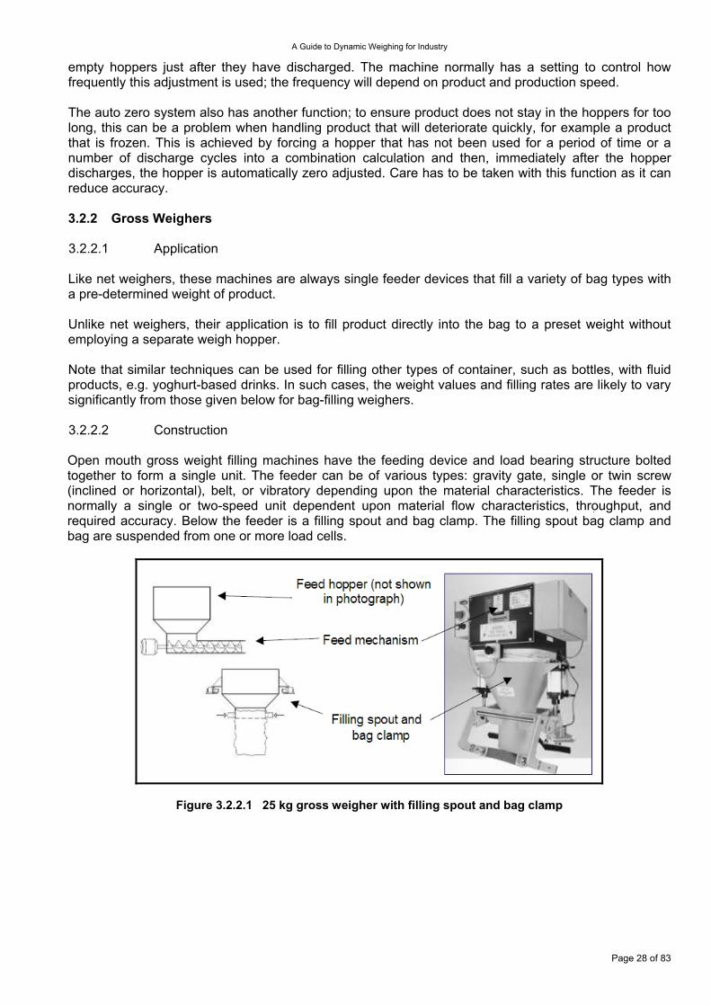
empty hoppers just after they have discharged. The machine normally has a setting to control how frequently this adjustment is used; the frequency will depend on product and production speed. The auto zero system also has another function; to ensure product does not stay in the hoppers for too long, this can be a problem when handling product that will deteriorate quickly, for example a product that is frozen. This is achieved by forcing a hopper that has not been used for a period of time or a number of discharge cycles into a combination calculation and then, immediately after the hopper discharges, the hopper is automatically zero adjusted. Care has to be taken with this function as it can reduce accuracy. 3.2.2 Gross Weighers 3.2.2.1 Application Like net weighers, these machines are always single feeder devices that fill a variety of bag types with a pre-determined weight of product. Unlike net weighers, their application is to fill product directly into the bag to a preset weight without employing a separate weigh hopper. Note that similar techniques can be used for filling other types of container, such as bottles, with fluid products, e.g. yoghurt-based drinks. In such cases, the weight values and filling rates are likely to vary significantly from those given below for bag-filling weighers. 3.2.2.2 Construction Open mouth gross weight filling machines have the feeding device and load bearing structure bolted together to form a single unit. The feeder can be of various types: gravity gate, single or twin screw (inclined or horizontal), belt, or vibratory depending upon the material characteristics. The feeder is normally a single or two-speed unit dependent upon material flow characteristics, throughput, and required accuracy. Below the feeder is a filling spout and bag clamp. The filling spout bag clamp and bag are suspended from one or more load cells.
Figure 3.2.2.1 25 kg gross weigher with filling spout and bag clamp
Page 28 of 83
A Guide to Dynamic Weighing for Industry
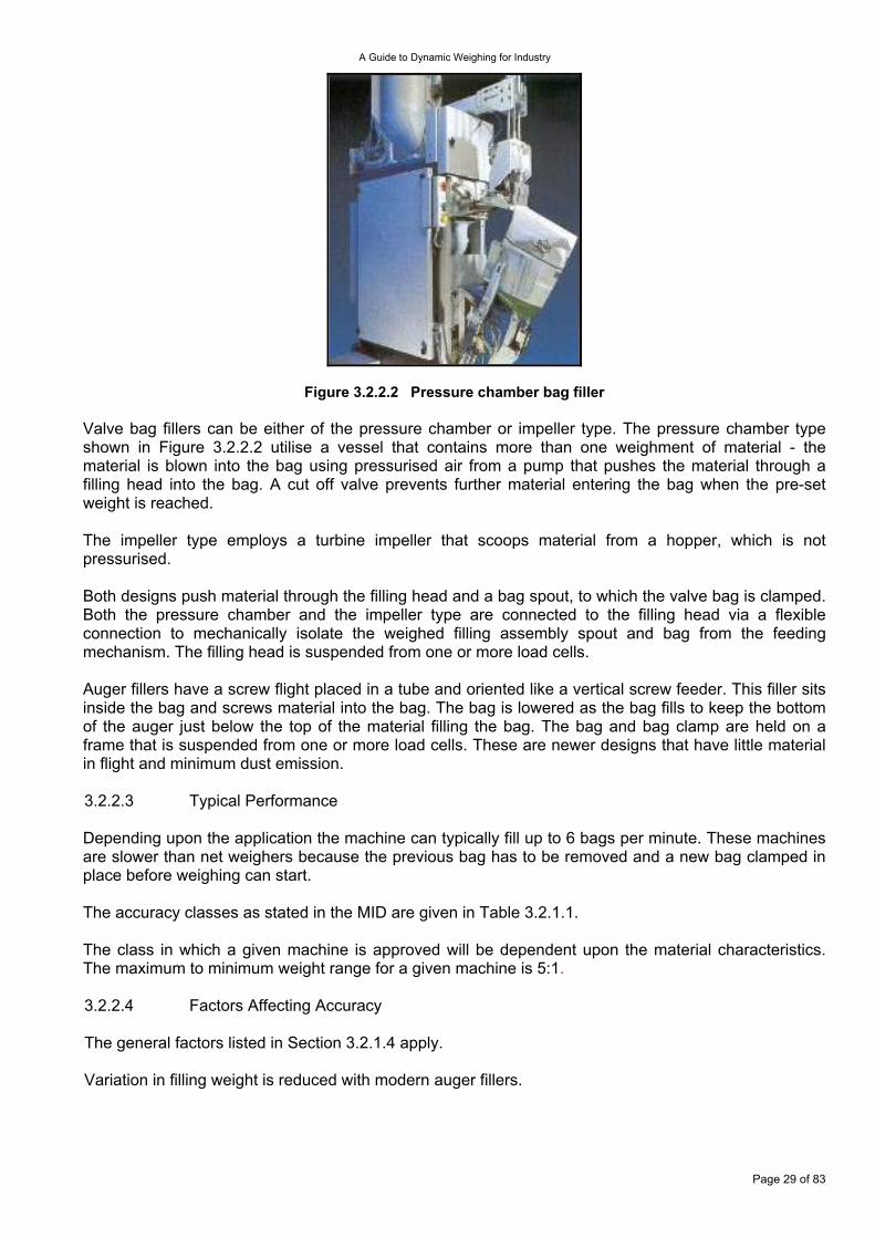
Figure 3.2.2.2 Pressure chamber bag filler Valve bag fillers can be either of the pressure chamber or impeller type. The pressure chamber type shown in Figure 3.2.2.2 utilise a vessel that contains more than one weighment of material - the material is blown into the bag using pressurised air from a pump that pushes the material through a filling head into the bag. A cut off valve prevents further material entering the bag when the pre-set weight is reached. The impeller type employs a turbine impeller that scoops material from a hopper, which is not pressurised. Both designs push material through the filling head and a bag spout, to which the valve bag is clamped. Both the pressure chamber and the impeller type are connected to the filling head via a flexible connection to mechanically isolate the weighed filling assembly spout and bag from the feeding mechanism. The filling head is suspended from one or more load cells. Auger fillers have a screw flight placed in a tube and oriented like a vertical screw feeder. This filler sits inside the bag and screws material into the bag. The bag is lowered as the bag fills to keep the bottom of the auger just below the top of the material filling the bag. The bag and bag clamp are held on a frame that is suspended from one or more load cells. These are newer designs that have little material in flight and minimum dust emission. 3.2.2.3 Typical Performance Depending upon the application the machine can typically fill up to 6 bags per minute. These machines are slower than net weighers because the previous bag has to be removed and a new bag clamped in place before weighing can start. The accuracy classes as stated in the MID are given in Table 3.2.1.1. The class in which a given machine is approved will be dependent upon the material characteristics. The maximum to minimum weight range for a given machine is 5:1. 3.2.2.4 Factors Affecting Accuracy The general factors listed in Section 3.2.1.4 apply. Variation in filling weight is reduced with modern auger fillers.
Page 29 of 83

A Guide to Dynamic Weighing for Industry
3.2.2.5 Calibration/Verification Initial verification of a legal for trade machine in the UK is performed in-situ by a Notified Body or by the manufacturer if approved (certified) to conduct ‘self-verification’. The procedure is to initially calibrate the zero (weigher empty) state and then to calibrate to a value slightly above the maximum capacity of the weigher, typically 26 kg for a 25 kg capacity machine or 52 kg for a 50 kg machine. This is done to prevent a machine from going into overload if a small over weighment cycle occurs. The MID does not specify how the verification test are performed so typically the procedures detailed in OIML R61 are used. In certain circumstances the instrument itself can be used as the control instrument but typically a separate control instrument is used. Subsequent calibration or verification can be performed by an approved verifier or an inspector. A recalibration sticker is then attached to the weigher and controller, and the results are documented for traceability purposes.
Page 30 of 83
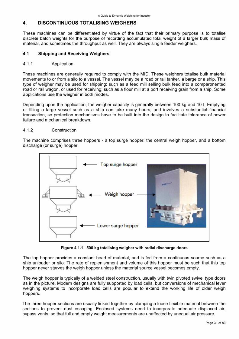
A Guide to Dynamic Weighing for Industry
4. DISCONTINUOUS TOTALISING WEIGHERS These machines can be differentiated by virtue of the fact that their primary purpose is to totalise discrete batch weights for the purpose of recording accumulated total weight of a larger bulk mass of material, and sometimes the throughput as well. They are always single feeder weighers. 4.1 Shipping and Receiving Weighers 4.1.1 Application These machines are generally required to comply with the MID. These weighers totalise bulk material movements to or from a silo to a vessel. The vessel may be a road or rail tanker, a barge or a ship. This type of weigher may be used for shipping; such as a feed mill selling bulk feed into a compartmented road or rail wagon, or used for receiving; such as a flour mill at a port receiving grain from a ship. Some applications use the weigher in both modes. Depending upon the application, the weigher capacity is generally between 100 kg and 10 t. Emptying or filling a large vessel such as a ship can take many hours, and involves a substantial financial transaction, so protection mechanisms have to be built into the design to facilitate tolerance of power failure and mechanical breakdown. 4.1.2 Construction The machine comprises three hoppers - a top surge hopper, the central weigh hopper, and a bottom discharge (or surge) hopper.
Figure 4.1.1 500 kg totalising weigher with radial discharge doors The top hopper provides a constant head of material, and is fed from a continuous source such as a ship unloader or silo. The rate of replenishment and volume of this hopper must be such that this top hopper never starves the weigh hopper unless the material source vessel becomes empty. The weigh hopper is typically of a welded steel construction, usually with twin pivoted swivel type doors as in the picture. Modern designs are fully supported by load cells, but conversions of mechanical lever weighing systems to incorporate load cells are popular to extend the working life of older weigh hoppers. The three hopper sections are usually linked together by clamping a loose flexible material between the sections to prevent dust escaping. Enclosed systems need to incorporate adequate displaced air, bypass vents, so that full and empty weight measurements are unaffected by unequal air pressure.
Page 31 of 83
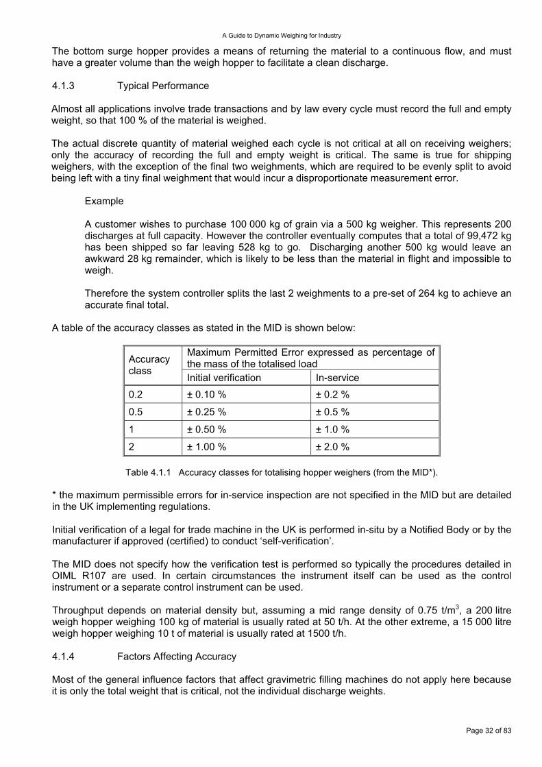
A Guide to Dynamic Weighing for Industry
The bottom surge hopper provides a means of returning the material to a continuous flow, and must have a greater volume than the weigh hopper to facilitate a clean discharge. 4.1.3 Typical Performance Almost all applications involve trade transactions and by law every cycle must record the full and empty weight, so that 100 % of the material is weighed. The actual discrete quantity of material weighed each cycle is not critical at all on receiving weighers; only the accuracy of recording the full and empty weight is critical. The same is true for shipping weighers, with the exception of the final two weighments, which are required to be evenly split to avoid being left with a tiny final weighment that would incur a disproportionate measurement error.
Example
A customer wishes to purchase 100 000 kg of grain via a 500 kg weigher. This represents 200 discharges at full capacity. However the controller eventually computes that a total of 99,472 kg has been shipped so far leaving 528 kg to go. Discharging another 500 kg would leave an awkward 28 kg remainder, which is likely to be less than the material in flight and impossible to weigh. Therefore the system controller splits the last 2 weighments to a pre-set of 264 kg to achieve an accurate final total.
A table of the accuracy classes as stated in the MID is shown below:
Maximum Permitted Error expressed as percentage of the mass of the totalised load Accuracy
class Initial verification In-service
0.2 ± 0.10 % ± 0.2 %
0.5 ± 0.25 % ± 0.5 %
1 ± 0.50 % ± 1.0 %
2 ± 1.00 % ± 2.0 %
Table 4.1.1 Accuracy classes for totalising hopper weighers (from the MID*).
* the maximum permissible errors for in-service inspection are not specified in the MID but are detailed in the UK implementing regulations. Initial verification of a legal for trade machine in the UK is performed in-situ by a Notified Body or by the manufacturer if approved (certified) to conduct ‘self-verification’. The MID does not specify how the verification test is performed so typically the procedures detailed in OIML R107 are used. In certain circumstances the instrument itself can be used as the control instrument or a separate control instrument can be used. Throughput depends on material density but, assuming a mid range density of 0.75 t/m3, a 200 litre weigh hopper weighing 100 kg of material is usually rated at 50 t/h. At the other extreme, a 15 000 litre weigh hopper weighing 10 t of material is usually rated at 1500 t/h. 4.1.4 Factors Affecting Accuracy Most of the general influence factors that affect gravimetric filling machines do not apply here because it is only the total weight that is critical, not the individual discharge weights.
Page 32 of 83
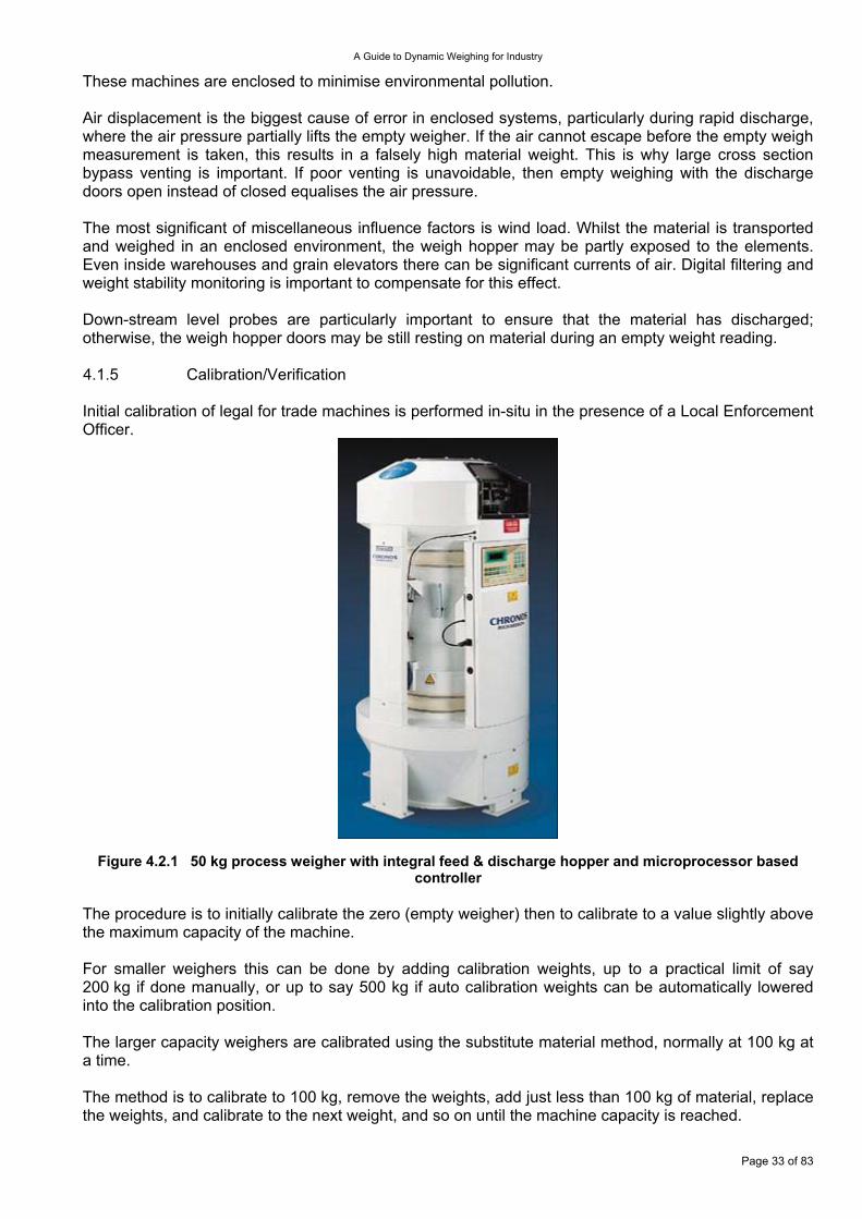
A Guide to Dynamic Weighing for Industry
These machines are enclosed to minimise environmental pollution. Air displacement is the biggest cause of error in enclosed systems, particularly during rapid discharge, where the air pressure partially lifts the empty weigher. If the air cannot escape before the empty weigh measurement is taken, this results in a falsely high material weight. This is why large cross section bypass venting is important. If poor venting is unavoidable, then empty weighing with the discharge doors open instead of closed equalises the air pressure. The most significant of miscellaneous influence factors is wind load. Whilst the material is transported and weighed in an enclosed environment, the weigh hopper may be partly exposed to the elements. Even inside warehouses and grain elevators there can be significant currents of air. Digital filtering and weight stability monitoring is important to compensate for this effect. Down-stream level probes are particularly important to ensure that the material has discharged; otherwise, the weigh hopper doors may be still resting on material during an empty weight reading. 4.1.5 Calibration/Verification Initial calibration of legal for trade machines is performed in-situ in the presence of a Local Enforcement Officer.
Figure 4.2.1 50 kg process weigher with integral feed & discharge hopper and microprocessor based controller
The procedure is to initially calibrate the zero (empty weigher) then to calibrate to a value slightly above the maximum capacity of the machine. For smaller weighers this can be done by adding calibration weights, up to a practical limit of say 200 kg if done manually, or up to say 500 kg if auto calibration weights can be automatically lowered into the calibration position. The larger capacity weighers are calibrated using the substitute material method, normally at 100 kg at a time. The method is to calibrate to 100 kg, remove the weights, add just less than 100 kg of material, replace the weights, and calibrate to the next weight, and so on until the machine capacity is reached.
Page 33 of 83
A Guide to Dynamic Weighing for Industry
Recalibration can be then done by an approved engineer in a similar manner and the machine given a new certificate. 4.2 In-Process Weighers These are used within a manufacturing process such as grain or rice milling. The weigher capacity is generally less than shipping and receiving weighers being typically only 50 kg or less. 4.2.1 Application Their primary use is to determine both the short and long-term cumulative process weights of a product stream within a milling process. They inform the miller of milling efficiency as the product streams are weighed after being sieved, as well as signalling potential problems. The weighers in a mill comprise a single up-stream weigher that dictates the throughput of the mill and a number of down-stream weighers that record the weight of material passing through each process stream 4.2.2 Construction Like the shipping and receiving weighers, they comprise a three-section hopper system, but in a more compact integral form measuring typically 25 kg – 100 kg per discharge. Millers want to minimise disruption to process flow, so the top hopper facilitates a constant infeed of product to accumulate. The weigh hopper is suspended from one or more load cells. The weigh hopper may be either square in cross section with radiused corners or circular as shown here between the flexible connections. Hygiene is crucial in these applications. The hopper volume is usually between 40 litres and 200 litres. The bottom surge hopper smoothes the product flow back into a continuous stream and therefore has a larger capacity than the weigh hopper. Adequate dust free air vents or air bypass displacement ducts are essential to accommodate air movements within the enclosed weighing system to maintain accuracy. A typical weigher is shown in Figure 4.2.1 with integral feed and discharge hoppers, and an integral microprocessor based controller with operator interface. 4.2.3 Typical Performance This very much depends upon whether it is operating as a sample weigher or 100 % product weigher. A weigher operating in a sampling mode leaves the feed and discharge gate open for most of the time, only closing the discharge gate for a sample period to record the weight per unit time hence approximate the throughput periodically. Accuracy is not considered critical here. The purpose of only sample weighing is to comply with the wishes of some millers, who prefer to keep any disturbance of the flow of the milled products to an absolute minimum, even at the expense of potentially reduced throughput accuracy. 100 % product weighers usually have a static accuracy specified as ±0.1 % of capacity. Dynamic accuracy is almost impossible to verify but probably approaches the static accuracy figure. Throughput is typically specified as between 5 t/hr and 50 t/hr depending upon hopper volume. These machines are not normally required to comply with Weights and Measures regulations in the EU, so empty weight recording can be omitted for increased throughput if the weigh hopper is of good design so that material build up is avoided. 4.2.4 Factors Affecting Accuracy. Air displacement in enclosed weighing systems is a major cause of error, particularly during empty weight recording. Air pressure built up during discharge as the material falls can partially lift the weigh hopper, if inadequate bypass venting is not incorporated within the design. The cross-sectional area of bypass venting pipes must be sufficiently large to rapidly equalise the air pressure changes caused by the discharge.
Page 34 of 83
A Guide to Dynamic Weighing for Industry
The positioning of the vent pipes must be such that material is not re-circulated with the moving air. It is common practice to ignore the empty weigh hopper weight recording on fast cycling machines to avoid this problem. The closing of the weigher discharge doors may also be interlocked with a downstream surge hopper level probe to prevent the doors being closed before the material has gone, ensuring that no material is trapped inside the closing doors that could be weighed twice Inadequate bypass venting is the biggest cause of error in enclosed systems. 4.2.5 Calibration/Verification Calibration of the weigher at zero and rated capacity is fairly easy because the rated capacity is relatively small. Some weighers have automatic calibration weights as a built in option.
Page 35 of 83

A Guide to Dynamic Weighing for Industry
5. IN-MOTION WEIGHING SYSTEMS These systems determine the mass of moving objects or material passing over or through the device. The measurand may be truly continuous, as in the case of a stream of particulate material passing over a belt weigher, or it may appear as discrete weighing events as in the form of vehicle axles or packages on a conveyor belt. 5.1 Continuous Weighing Systems In the case where the material to be weighed is in the form of a continuous stream, the mass flow rate is determined and this quantity may be used for control or to give a determination of the total mass transferred or delivered. The scope of this section is limited to methods that depend on the determination of mass flow rate by the use of gravity (with the exception of momentum change mass flow meters – see below). Indirect determination of mass flow rate by, for example, thermal or radiometric techniques is not included. 5.1.1 Belt Weighers 5.1.1.1 Application Conveyor belt systems are used for the continuous transport of a wide range of powders and granular materials (bulk solids) within a wide range of industries, such as: agricultural, pharmaceutical, mining and quarrying, power generation, and food processing. A belt weigher may be incorporated into the conveying line and the instantaneous mass flow rate of the material moving along the belt may be established. This determination may then be used to obtain a mass feed rate in a continuous process or totalised over time to measure the total amount of material delivered. The performance of belt-weighers is such that, if so designated, they may be used to determine the amount of material in ‘legal for trade’ applications. The definition of a belt weigher used in this section is - an automatic weighing instrument for continuously weighing a bulk product on a conveyor belt by the action of gravity without systematic subdivision of the mass and without interrupting the movement of the conveyor belt. Belt weighers deduce the mass flow rate of material from two distinct measurements, namely: the weight of a section of the belt transporting material and the speed of the belt. The total mass of material transported in a particular time can then be calculated by integrating (totalising) the mass flow rate over that time. The general form of a belt weigher is presented in Figure 5.1.1.1.
Figure 5.1.1.1 Schematic representation of a belt weigher The following analysis makes the simplifying assumption that any section of belt and the bulk material it carries is fully supported by the two closest rollers. This being the case, the full weight of product distributed on the belt (and indeed the weight of the belt) in the region LB of Figure 5.1.1.1 will
Page 36 of 83
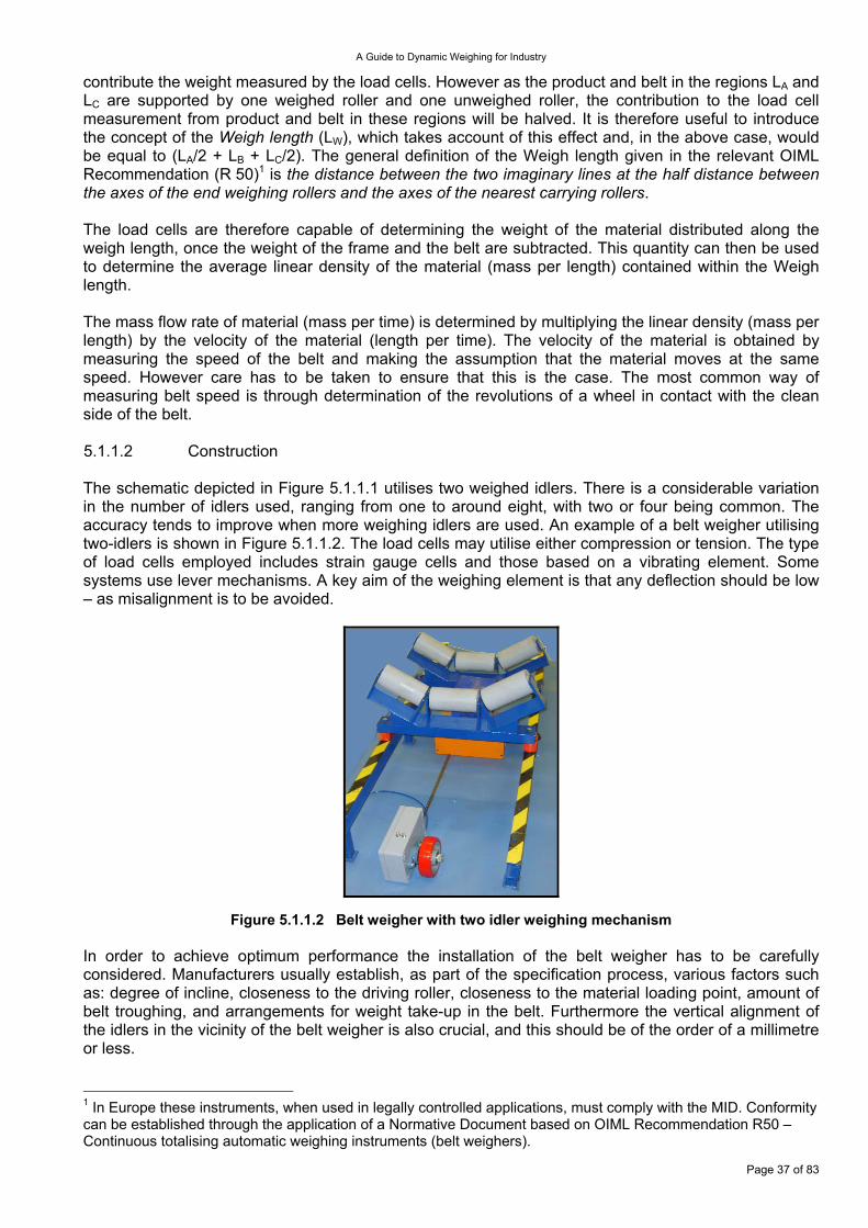
A Guide to Dynamic Weighing for Industry
contribute the weight measured by the load cells. However as the product and belt in the regions LA and LC are supported by one weighed roller and one unweighed roller, the contribution to the load cell measurement from product and belt in these regions will be halved. It is therefore useful to introduce the concept of the Weigh length (LW), which takes account of this effect and, in the above case, would be equal to (LA/2 + LB + LC/2). The general definition of the Weigh length given in the relevant OIML Recommendation (R 50)1 is the distance between the two imaginary lines at the half distance between the axes of the end weighing rollers and the axes of the nearest carrying rollers. The load cells are therefore capable of determining the weight of the material distributed along the weigh length, once the weight of the frame and the belt are subtracted. This quantity can then be used to determine the average linear density of the material (mass per length) contained within the Weigh length. The mass flow rate of material (mass per time) is determined by multiplying the linear density (mass per length) by the velocity of the material (length per time). The velocity of the material is obtained by measuring the speed of the belt and making the assumption that the material moves at the same speed. However care has to be taken to ensure that this is the case. The most common way of measuring belt speed is through determination of the revolutions of a wheel in contact with the clean side of the belt. 5.1.1.2 Construction The schematic depicted in Figure 5.1.1.1 utilises two weighed idlers. There is a considerable variation in the number of idlers used, ranging from one to around eight, with two or four being common. The accuracy tends to improve when more weighing idlers are used. An example of a belt weigher utilising two-idlers is shown in Figure 5.1.1.2. The load cells may utilise either compression or tension. The type of load cells employed includes strain gauge cells and those based on a vibrating element. Some systems use lever mechanisms. A key aim of the weighing element is that any deflection should be low – as misalignment is to be avoided.
Figure 5.1.1.2 Belt weigher with two idler weighing mechanism In order to achieve optimum performance the installation of the belt weigher has to be carefully considered. Manufacturers usually establish, as part of the specification process, various factors such as: degree of incline, closeness to the driving roller, closeness to the material loading point, amount of belt troughing, and arrangements for weight take-up in the belt. Furthermore the vertical alignment of the idlers in the vicinity of the belt weigher is also crucial, and this should be of the order of a millimetre or less.
Page 37 of 83
1 In Europe these instruments, when used in legally controlled applications, must comply with the MID. Conformity can be established through the application of a Normative Document based on OIML Recommendation R50 – Continuous totalising automatic weighing instruments (belt weighers).
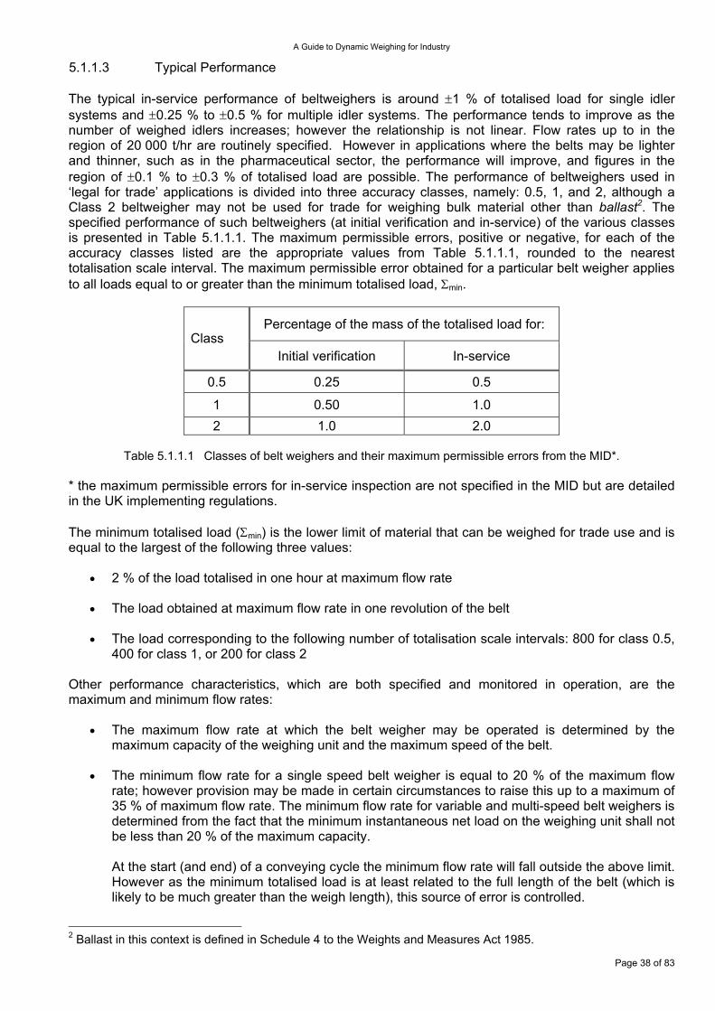
A Guide to Dynamic Weighing for Industry
5.1.1.3 Typical Performance The typical in-service performance of beltweighers is around ±1 % of totalised load for single idler systems and ±0.25 % to ±0.5 % for multiple idler systems. The performance tends to improve as the number of weighed idlers increases; however the relationship is not linear. Flow rates up to in the region of 20 000 t/hr are routinely specified. However in applications where the belts may be lighter and thinner, such as in the pharmaceutical sector, the performance will improve, and figures in the region of ±0.1 % to ±0.3 % of totalised load are possible. The performance of beltweighers used in ‘legal for trade’ applications is divided into three accuracy classes, namely: 0.5, 1, and 2, although a Class 2 beltweigher may not be used for trade for weighing bulk material other than ballast2. The specified performance of such beltweighers (at initial verification and in-service) of the various classes is presented in Table 5.1.1.1. The maximum permissible errors, positive or negative, for each of the accuracy classes listed are the appropriate values from Table 5.1.1.1, rounded to the nearest totalisation scale interval. The maximum permissible error obtained for a particular belt weigher applies to all loads equal to or greater than the minimum totalised load, Σmin.
Percentage of the mass of the totalised load for: Class
Initial verification In-service
0.5 0.25 0.5
1 0.50 1.0 2 1.0 2.0
Table 5.1.1.1 Classes of belt weighers and their maximum permissible errors from the MID*.
* the maximum permissible errors for in-service inspection are not specified in the MID but are detailed in the UK implementing regulations. The minimum totalised load (Σmin) is the lower limit of material that can be weighed for trade use and is equal to the largest of the following three values:
•
•
•
•
•
2 % of the load totalised in one hour at maximum flow rate
The load obtained at maximum flow rate in one revolution of the belt
The load corresponding to the following number of totalisation scale intervals: 800 for class 0.5, 400 for class 1, or 200 for class 2
Other performance characteristics, which are both specified and monitored in operation, are the maximum and minimum flow rates:
The maximum flow rate at which the belt weigher may be operated is determined by the maximum capacity of the weighing unit and the maximum speed of the belt.
The minimum flow rate for a single speed belt weigher is equal to 20 % of the maximum flow rate; however provision may be made in certain circumstances to raise this up to a maximum of 35 % of maximum flow rate. The minimum flow rate for variable and multi-speed belt weighers is determined from the fact that the minimum instantaneous net load on the weighing unit shall not be less than 20 % of the maximum capacity.
At the start (and end) of a conveying cycle the minimum flow rate will fall outside the above limit. However as the minimum totalised load is at least related to the full length of the belt (which is likely to be much greater than the weigh length), this source of error is controlled.
2 Ballast in this context is defined in Schedule 4 to the Weights and Measures Act 1985.
Page 38 of 83
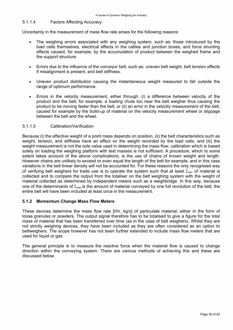
A Guide to Dynamic Weighing for Industry
5.1.1.4 Factors Affecting Accuracy Uncertainty in the measurement of mass flow rate arises for the following reasons:
The weighing errors associated with any weighing system, such as: those introduced by the load cells themselves, electrical effects in the cables and junction boxes, and force shunting effects caused, for example, by the accumulation of product between the weighed frame and the support structure.
•
•
•
•
Errors due to the influence of the conveyor belt, such as: uneven belt weight, belt tension effects if misalignment is present, and belt stiffness.
Uneven product distribution causing the instantaneous weight measured to fall outside the range of optimum performance.
Errors in the velocity measurement, either through: (i) a difference between velocity of the product and the belt, for example, a loading chute too near the belt weigher thus causing the product to be moving faster than the belt, or (ii) an error in the velocity measurement of the belt, caused for example by the build-up of material on the velocity measurement wheel or slippage between the belt and the wheel.
5.1.1.5 Calibration/Verification Because (i) the effective weight of a point mass depends on position, (ii) the belt characteristics such as weight, tension, and stiffness have an effect on the weight recorded by the load cells, and (iii) the weight measurement is not the sole value used in determining the mass flow, calibration which is based solely on loading the weighing platform with test masses is not sufficient. A procedure, which to some extent takes account of the above complications, is the use of chains of known weight and length. However chains are unlikely to exceed or even equal the length of the belt for example, and in this case variations in the belt linear density will not be accounted for. For these reasons the only recognised way of verifying belt weighers for trade use is to operate the system such that at least Σmin of material is collected and to compare the output from the totaliser on the belt weighing system with the weight of material collected as determined by independent means such as a weighbridge. In this way, because one of the determinants of Σmin is the amount of material conveyed by one full revolution of the belt, the entire belt will have been included at least once in the measurement. 5.1.2 Momentum Change Mass Flow Meters These devices determine the mass flow rate [t/hr, kg/s] of particulate material, either in the form of loose granules or powders. The output signal therefore has to be totalised to give a figure for the total mass of material that has been transferred over time (as in the case of belt weighers). Whilst they are not strictly weighing devices, they have been included as they are often considered as an option to beltweighers. The scope however has not been further extended to include mass flow meters that are used for liquid or gas. The general principle is to measure the reactive force when the material flow is caused to change direction within the conveying system. There are various methods of achieving this and these are discussed below.
Page 39 of 83
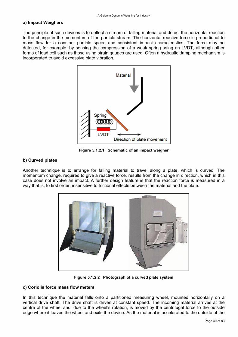
A Guide to Dynamic Weighing for Industry
a) Impact Weighers The principle of such devices is to deflect a stream of falling material and detect the horizontal reaction to the change in the momentum of the particle stream. The horizontal reactive force is proportional to mass flow for a constant particle speed and consistent impact characteristics. The force may be detected, for example, by sensing the compression of a weak spring using an LVDT, although other forms of load cell such as those using strain gauges are used. Often a hydraulic damping mechanism is incorporated to avoid excessive plate vibration.
Figure 5.1.2.1 Schematic of an impact weigher b) Curved plates Another technique is to arrange for falling material to travel along a plate, which is curved. The momentum change, required to give a reactive force, results from the change in direction, which in this case does not involve an impact. A further design feature is that the reaction force is measured in a way that is, to first order, insensitive to frictional effects between the material and the plate.
Figure 5.1.2.2 Photograph of a curved plate system c) Coriolis force mass flow meters
Page 40 of 83
In this technique the material falls onto a partitioned measuring wheel, mounted horizontally on a vertical drive shaft. The drive shaft is driven at constant speed. The incoming material arrives at the centre of the wheel and, due to the wheel’s rotation, is moved by the centrifugal force to the outside edge where it leaves the wheel and exits the device. As the material is accelerated to the outside of the
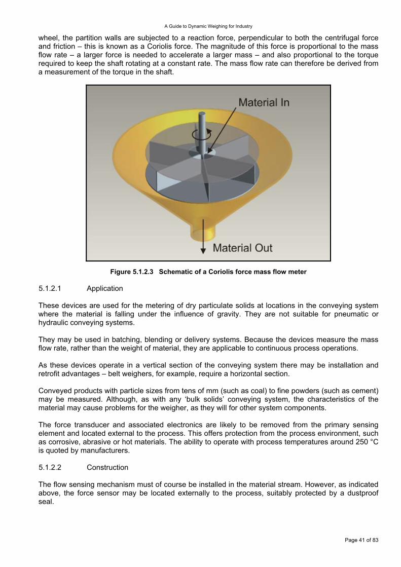
A Guide to Dynamic Weighing for Industry
wheel, the partition walls are subjected to a reaction force, perpendicular to both the centrifugal force and friction – this is known as a Coriolis force. The magnitude of this force is proportional to the mass flow rate – a larger force is needed to accelerate a larger mass – and also proportional to the torque required to keep the shaft rotating at a constant rate. The mass flow rate can therefore be derived from a measurement of the torque in the shaft.
Figure 5.1.2.3 Schematic of a Coriolis force mass flow meter 5.1.2.1 Application These devices are used for the metering of dry particulate solids at locations in the conveying system where the material is falling under the influence of gravity. They are not suitable for pneumatic or hydraulic conveying systems. They may be used in batching, blending or delivery systems. Because the devices measure the mass flow rate, rather than the weight of material, they are applicable to continuous process operations. As these devices operate in a vertical section of the conveying system there may be installation and retrofit advantages – belt weighers, for example, require a horizontal section. Conveyed products with particle sizes from tens of mm (such as coal) to fine powders (such as cement) may be measured. Although, as with any ‘bulk solids’ conveying system, the characteristics of the material may cause problems for the weigher, as they will for other system components. The force transducer and associated electronics are likely to be removed from the primary sensing element and located external to the process. This offers protection from the process environment, such as corrosive, abrasive or hot materials. The ability to operate with process temperatures around 250 °C is quoted by manufacturers. 5.1.2.2 Construction The flow sensing mechanism must of course be installed in the material stream. However, as indicated above, the force sensor may be located externally to the process, suitably protected by a dustproof seal.
Page 41 of 83
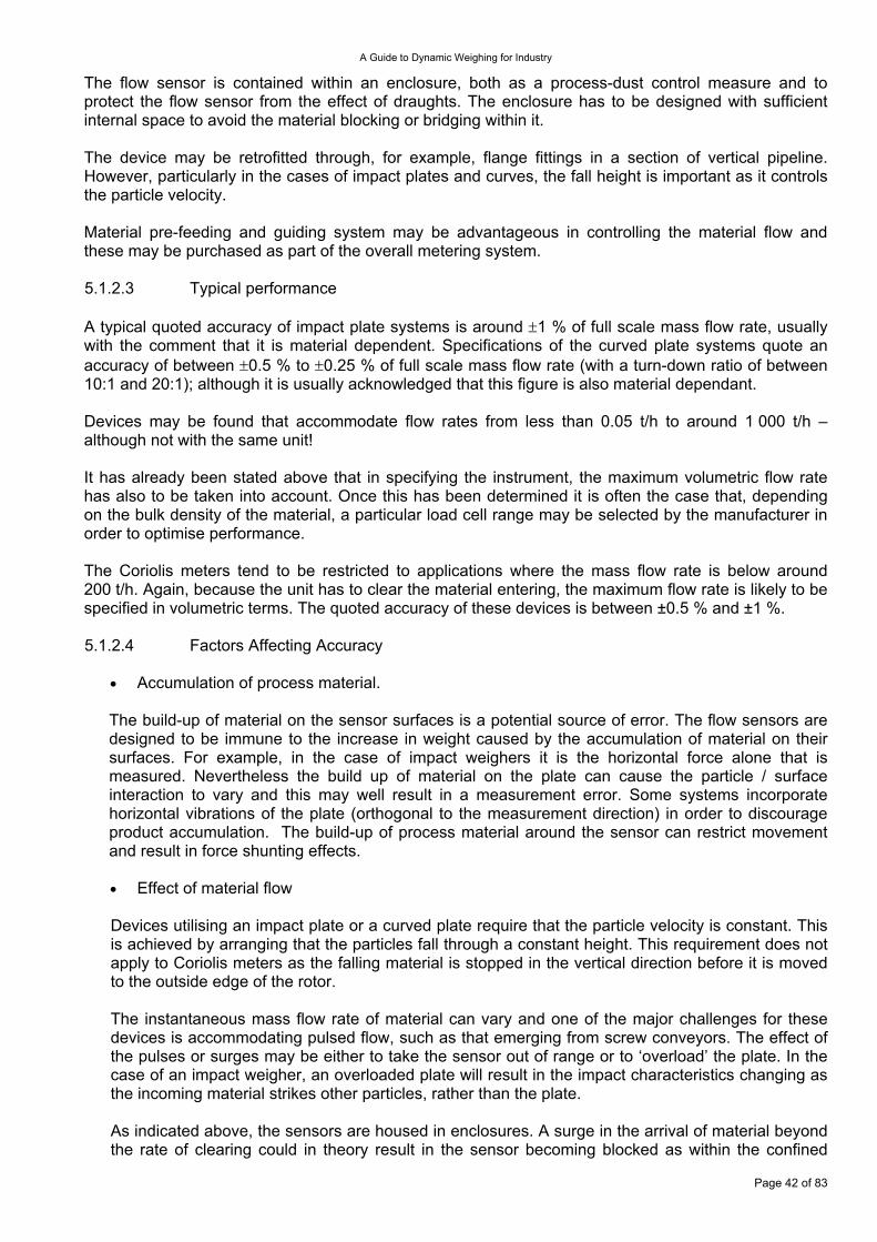
A Guide to Dynamic Weighing for Industry
The flow sensor is contained within an enclosure, both as a process-dust control measure and to protect the flow sensor from the effect of draughts. The enclosure has to be designed with sufficient internal space to avoid the material blocking or bridging within it. The device may be retrofitted through, for example, flange fittings in a section of vertical pipeline. However, particularly in the cases of impact plates and curves, the fall height is important as it controls the particle velocity. Material pre-feeding and guiding system may be advantageous in controlling the material flow and these may be purchased as part of the overall metering system. 5.1.2.3 Typical performance A typical quoted accuracy of impact plate systems is around ±1 % of full scale mass flow rate, usually with the comment that it is material dependent. Specifications of the curved plate systems quote an accuracy of between ±0.5 % to ±0.25 % of full scale mass flow rate (with a turn-down ratio of between 10:1 and 20:1); although it is usually acknowledged that this figure is also material dependant. Devices may be found that accommodate flow rates from less than 0.05 t/h to around 1 000 t/h – although not with the same unit! It has already been stated above that in specifying the instrument, the maximum volumetric flow rate has also to be taken into account. Once this has been determined it is often the case that, depending on the bulk density of the material, a particular load cell range may be selected by the manufacturer in order to optimise performance. The Coriolis meters tend to be restricted to applications where the mass flow rate is below around 200 t/h. Again, because the unit has to clear the material entering, the maximum flow rate is likely to be specified in volumetric terms. The quoted accuracy of these devices is between ±0.5 % and ±1 %. 5.1.2.4 Factors Affecting Accuracy
Accumulation of process material. •
•
The build-up of material on the sensor surfaces is a potential source of error. The flow sensors are designed to be immune to the increase in weight caused by the accumulation of material on their surfaces. For example, in the case of impact weighers it is the horizontal force alone that is measured. Nevertheless the build up of material on the plate can cause the particle / surface interaction to vary and this may well result in a measurement error. Some systems incorporate horizontal vibrations of the plate (orthogonal to the measurement direction) in order to discourage product accumulation. The build-up of process material around the sensor can restrict movement and result in force shunting effects.
Effect of material flow
Devices utilising an impact plate or a curved plate require that the particle velocity is constant. This is achieved by arranging that the particles fall through a constant height. This requirement does not apply to Coriolis meters as the falling material is stopped in the vertical direction before it is moved to the outside edge of the rotor. The instantaneous mass flow rate of material can vary and one of the major challenges for these devices is accommodating pulsed flow, such as that emerging from screw conveyors. The effect of the pulses or surges may be either to take the sensor out of range or to ‘overload’ the plate. In the case of an impact weigher, an overloaded plate will result in the impact characteristics changing as the incoming material strikes other particles, rather than the plate. As indicated above, the sensors are housed in enclosures. A surge in the arrival of material beyond the rate of clearing could in theory result in the sensor becoming blocked as within the confined
Page 42 of 83
A Guide to Dynamic Weighing for Industry
space particle / particle interaction may result in bridging. It is therefore important to consider the peak volumetric flow rate in addition to the average mass flow rate when specifying the system parameters.
Other effects •
As mentioned above, draughts can exert additional forces on sensing plates. However this problem may be minimised by enclosing the flow sensor within a suitable enclosure. The surfaces of the flow sensor may also be subject to degradation and corrosion. Through the inherent design of the units, the loss in the weight of the plate due to factors such as corrosion will have minimum effect. However the changes in surface characteristics of the plate may be significant. Manufacturers supply a variety of surface coatings, which may be selected for particular process materials.
5.1.2.5 Calibration/Verification Many operating handbooks for these devices describe methods for testing the force measurement device using weights, and this is sometimes referred to as calibration. The performance of the devices however is sufficiently material dependent that the only secure means of calibration is through material tests. Such tests involve operating the instrument, collecting the material conveyed and comparing the indication of the totalised value to the weight of the collected material established by a separate control instrument. Such a process should, of course, be carried out for all materials used over the entire range of mass flow rate encountered. 5.1.3 Weighed Feeders (Loss of Weight Feeders) A loss of weight feeder controls the dispensing of material by weight into a process at a precise rate. The target feed rate is generally known as the loss of weight setpoint. The measuring units of such setpoints may vary from grams per second in some pharmaceutical applications, right through to tonnes per hour in heavy industrial processes.
Figure 5.1.3.1 A typical loss of weight feeder complete with electronic controller
Page 43 of 83
A Guide to Dynamic Weighing for Industry
5.1.3.1 Application The ability of loss of weight feeders to provide a continuous delivery of material at a predetermined rate, has resulted in their utilisation in various continuous production processes, including the supply of raw material into extruders. However, a more typical application would be in a food production line employing a continuous process, which may utilise several loss of weight feeders, each dispensing different material ingredients at different feed rates (often onto a common moving belt). Here, the proportioning of the individual feed rates determines the final product recipe, and the sum of the individual feed rates determines the output of the production line. Such systems may also incorporate beltweighers delivering bulk materials into the process, (also at a predetermined rate). The complete system is then typically controlled by a central PLC/SCADA control system. These continuous loss of weight processes are often more efficient than conventional process batch weighers (see Section 3.1), where the material delivery must be periodically suspended, whilst the weigh vessel is replenished and the next batch is prepared. 5.1.3.1.1 Volumetric Feeding The principle of volumetric feeding is accomplished by simply relying on the volumetric properties of feeder to deliver product at a constant rate. For example, if a known preset motor speed is applied to a screw feeder, then theoretically, a constant volume of material will pass through the feeder per unit time. Volumetric feeding incorporates no feedback and is therefore ‘open loop’, thus limiting its potential accuracy. The principle sources of error are as follows:-
Material density variations, which will alter the weight of the material delivered (for constant volumetric delivery)
•
•
•
Feeder flow rate errors, resulting from discrepancies between the preset (desired) speed of the feeder and the actual speed, and thus volumetric delivery rate (and there is no feedback present to detect or correct this)
Material flow inconsistencies within the feeder mechanism (perhaps material becoming mechanically stuck to the feeder components)
It is therefore clear that pure volumetric feeders have significant accuracy limitations. However, they do provide an efficient economical solution to non-critical applications. 5.1.3.1.2 Gravimetric (Loss of Weight) Feeding A gravimetric (loss of weight) feeder is implemented by utilising a weighing system configured to weigh the whole hopper/feeder system, together with its contents (the product to be fed). The basic loss of weight principle is to dispense the product at a constant loss of weight per unit time t, such that the material weight w, contained in the hopper is delivered by the feeder according to the rule:
=dtdw constant
Page 44 of 83
Consider the typical loss of weight control system configuration illustrated in Figure 5.1.3.2. In this example the electronic continuous weighing controller reads the load cell signals, at the same time as controlling the feeder motor, and hence the feeder speed. A tachometer is also employed to measure the actual motor speed, which is fed back to an input on the weighing/motor controller. All this information is used by the control system to set the optimum motor speed (typically using 2 term control algorithms), to deliver product by weight at the desired rate (the setpoint). Some more sophisticated controllers also compare the totalised quantity of material actually fed over a period of time against the target and, following calculation, execute incremental corrective changes to the feeder speed to optimise long-term feeder accuracy.
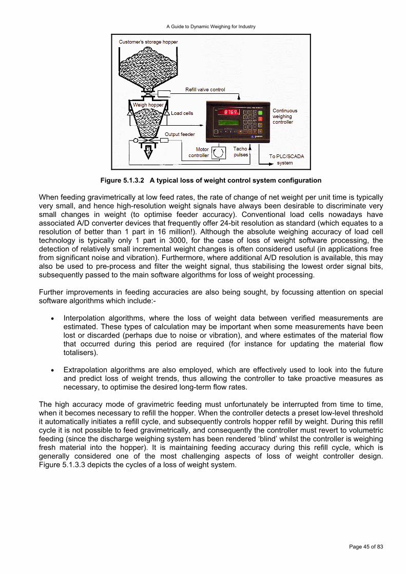
A Guide to Dynamic Weighing for Industry
Figure 5.1.3.2 A typical loss of weight control system configuration When feeding gravimetrically at low feed rates, the rate of change of net weight per unit time is typically very small, and hence high-resolution weight signals have always been desirable to discriminate very small changes in weight (to optimise feeder accuracy). Conventional load cells nowadays have associated A/D converter devices that frequently offer 24-bit resolution as standard (which equates to a resolution of better than 1 part in 16 million!). Although the absolute weighing accuracy of load cell technology is typically only 1 part in 3000, for the case of loss of weight software processing, the detection of relatively small incremental weight changes is often considered useful (in applications free from significant noise and vibration). Furthermore, where additional A/D resolution is available, this may also be used to pre-process and filter the weight signal, thus stabilising the lowest order signal bits, subsequently passed to the main software algorithms for loss of weight processing. Further improvements in feeding accuracies are also being sought, by focussing attention on special software algorithms which include:-
Interpolation algorithms, where the loss of weight data between verified measurements are estimated. These types of calculation may be important when some measurements have been lost or discarded (perhaps due to noise or vibration), and where estimates of the material flow that occurred during this period are required (for instance for updating the material flow totalisers).
•
•
Extrapolation algorithms are also employed, which are effectively used to look into the future and predict loss of weight trends, thus allowing the controller to take proactive measures as necessary, to optimise the desired long-term flow rates.
The high accuracy mode of gravimetric feeding must unfortunately be interrupted from time to time, when it becomes necessary to refill the hopper. When the controller detects a preset low-level threshold it automatically initiates a refill cycle, and subsequently controls hopper refill by weight. During this refill cycle it is not possible to feed gravimetrically, and consequently the controller must revert to volumetric feeding (since the discharge weighing system has been rendered ‘blind’ whilst the controller is weighing fresh material into the hopper). It is maintaining feeding accuracy during this refill cycle, which is generally considered one of the most challenging aspects of loss of weight controller design. Figure 5.1.3.3 depicts the cycles of a loss of weight system.
Page 45 of 83
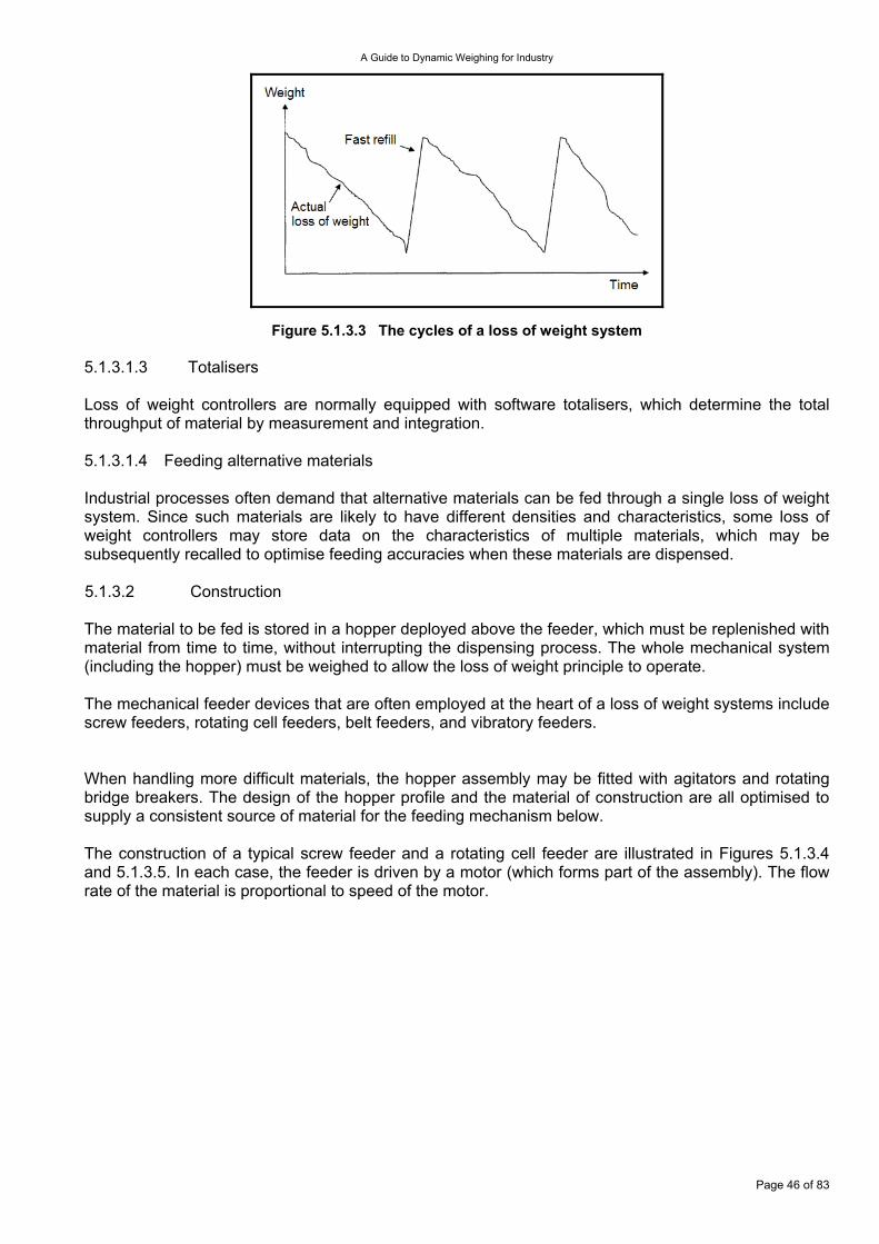
A Guide to Dynamic Weighing for Industry
Figure 5.1.3.3 The cycles of a loss of weight system 5.1.3.1.3 Totalisers Loss of weight controllers are normally equipped with software totalisers, which determine the total throughput of material by measurement and integration. 5.1.3.1.4 Feeding alternative materials Industrial processes often demand that alternative materials can be fed through a single loss of weight system. Since such materials are likely to have different densities and characteristics, some loss of weight controllers may store data on the characteristics of multiple materials, which may be subsequently recalled to optimise feeding accuracies when these materials are dispensed. 5.1.3.2 Construction The material to be fed is stored in a hopper deployed above the feeder, which must be replenished with material from time to time, without interrupting the dispensing process. The whole mechanical system (including the hopper) must be weighed to allow the loss of weight principle to operate. The mechanical feeder devices that are often employed at the heart of a loss of weight systems include screw feeders, rotating cell feeders, belt feeders, and vibratory feeders. When handling more difficult materials, the hopper assembly may be fitted with agitators and rotating bridge breakers. The design of the hopper profile and the material of construction are all optimised to supply a consistent source of material for the feeding mechanism below. The construction of a typical screw feeder and a rotating cell feeder are illustrated in Figures 5.1.3.4 and 5.1.3.5. In each case, the feeder is driven by a motor (which forms part of the assembly). The flow rate of the material is proportional to speed of the motor.
Page 46 of 83

A Guide to Dynamic Weighing for Industry
Figure 5.1.3.4 A screw feeder system
Figure 5.1.3.5 A cell feeder system The feeding mechanism may be a vibratory feeder, where material is fed from a hopper onto a vibrating tray. The material is then fed off the end of the tray, with a feed rate that is a function of the amplitude of the tray vibrations. Typically, the tray is vibrated electromechanically or pneumatically.
Page 47 of 83
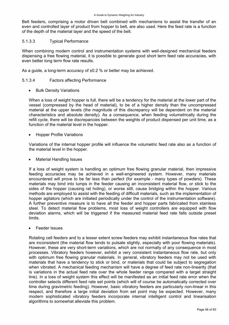
A Guide to Dynamic Weighing for Industry
Belt feeders, comprising a motor driven belt combined with mechanisms to assist the transfer of an even and controlled layer of product from hopper to belt, are also used. Here the feed rate is a function of the depth of the material layer and the speed of the belt. 5.1.3.3 Typical Performance When combining modern control and instrumentation systems with well-designed mechanical feeders dispensing a free flowing material, it is possible to generate good short term feed rate accuracies, with even better long term flow rate results. As a guide, a long-term accuracy of ±0.2 % or better may be achieved. 5.1.3.4 Factors affecting Performance
• Bulk Density Variations When a loss of weight hopper is full, there will be a tendency for the material at the lower part of the vessel (compressed by the head of material), to be of a higher density than the uncompressed material at the upper levels (the magnitude of this discrepancy will be dependent on the material characteristics and absolute density). As a consequence, when feeding volumetrically during the refill cycle, there will be discrepancies between the weights of product dispensed per unit time, as a function of the material level in the hopper. • Hopper Profile Variations Variations of the internal hopper profile will influence the volumetric feed rate also as a function of the material level in the hopper. • Material Handling Issues If a loss of weight system is handling an optimum free flowing granular material, then impressive feeding accuracies may be achieved in a well-engineered system. However, many materials encountered will prove to be far less than perfect (for example - many types of powders). These materials may bind into lumps in the feeder causing an inconsistent material flow, or stick to the sides of the hopper (causing rat holing), or worse still, cause bridging within the hopper. Various methods are employed to assist with the feeding of difficult materials, such as the implementation of hopper agitators (which are initiated periodically under the control of the instrumentation software). A further preventive measure is to have all the feeder and hopper parts fabricated from stainless steel. To detect material flow problems, most loss of weight controllers are equipped with flow deviation alarms, which will be triggered if the measured material feed rate falls outside preset limits. • Feeder Issues
Page 48 of 83
Rotating cell feeders and to a lesser extent screw feeders may exhibit instantaneous flow rates that are inconsistent (the material flow tends to pulsate slightly, especially with poor flowing materials). However, these are very short-term variations, which are not normally of any consequence in most processes. Vibratory feeders however, exhibit a very consistent instantaneous flow rate, but only with optimum free flowing granular materials. In general, vibratory feeders may not be used with materials that have a tendency to stick or bind, or materials that could be subject to segregation when vibrated. A mechanical feeding mechanism will have a degree of feed rate non-linearity (that is variations in the actual feed rate over the whole feeder range compared with a target straight line). In a loss of weight system this effect will be manifested as an initial feed rate error when the controller selects different feed rate set points (which will of course be automatically corrected over time during gravimetric feeding). However, basic vibratory feeders are particularly non-linear in this respect, and therefore a large initial deviation from set point may be expected. However, many modern sophisticated vibratory feeders incorporate internal intelligent control and linearisation algorithms to somewhat alleviate this problem.

A Guide to Dynamic Weighing for Industry
• Shock and Vibration In many environments, loss of weight systems may be subject to occasional physical disturbances, which can potentially upset the sensitive process of gravimetric feeding. Typical sources of such disturbances include general plant vibrations together with accidental physical impacts. Such disturbances may be mechanically minimised by the use of mechanical shock mounts, and the use of flexible process connections to the loss of weight system (this is especially helpful in blocking the transmission of vibrations). Furthermore, modern electronic loss of weight controllers incorporate intelligent digital filtering that greatly attenuate disturbances in the weight signals, and most controllers may also be configured to detect significant disturbances in the weight signals, and automatically revert to volumetric feeding during such periods. • Refill Valve Failure In practice, another common source of inaccuracies in loss of weight systems occurs when the refill valve fails to close completely, and thus a trickle of material is still being fed into the hopper during the normal gravimetric feeding cycle, upsetting the feeding measurement process.
The feedback from the weighing system is used to make automatic compensations (‘closed loop’ control) during the gravimetric cycle, to reduce the effect of these variations on the overall system performance. With simple loss of weight controller systems, it is common to hear a sudden change in feeder speed at end of the refill cycle (known as a bump!). This is when the controller (having reverted to gravimetric feeding) is correcting for discrepancies between the volumetric feed rate applied during the refill cycle, and the required feed rate as calculated in the gravimetric mode. However, sophisticated modern loss of weight controllers apply software algorithms to regularly adjust the volumetric feed rate during the refill cycle (as a function of the level of material as weighed in the hopper), with a view to compensating for the sources of error described above. Further improvements in overall system accuracy may be obtained, by the expedient measure of keeping the refill cycle as short as possible (or more precisely keeping the mark/space ratio of gravimetric feeding to refill cycle time as large as possible - typically at least 4:1). However, such measures tend to demand the provision of larger and larger hopper sizes, and since there are often limitations in physical space, the final choice of hopper size will normally become a compromise. 5.1.3.5 Calibration/Verification A loss of weight system is initially calibrated statically (known as the static weight calibration); to achieve this, the primary controller display (normally used to display flow rate) is often switched to display static weight (as with a conventional weighing indicator), and then a static weighing calibration carried out in a conventional manner using traceable standard or reference weights. Subsequently, the flow rate accuracy may be verified. Typically this may involve running the feeder, whilst diverting the material to an alternative destination for a set period of time (using a stop watch). This sample batch of material is then weighed on a conventional weigh scale. The sample weight may then be compared with the theoretical quantity, which should have been dispensed (determined from the feed rate set point and the interval of time recorded). The total weight of the sample batch may also be compared with the amount of material purported to have been fed, according to information in the controller’s totalisers. In normal operation, the purported material flow rate may be read from the feed rate display on the loss of weight controller. The controller derives this flow rate from the weight signal (statically calibrated), and its internal clock, from which it may calculate the weight dispensed per unit time (the flow rate). The fundamental calibration of a loss of weight system is its flow rate calibration, which is derived from the system static weight on and its internal clock. Therefore the overall calibration uncertainty of the system will be a function of the uncertainties of the static weighing and clock calibrations.
Page 49 of 83
A Guide to Dynamic Weighing for Industry
5.2 Discrete Mass Weighing Systems These systems both measure the discrete mass as it passes over the weighing platform, and accumulate a total weight. The measurement can be triggered from the weight on the platform increasing or from external triggers.
Figure 5.2.1.1 Weighing in motion For example weighing coal wagons in a train may involve weighing individual axle weights that are accumulated into individual wagon weights, and then the total train weight, eliminating the locomotive weight, and the empty wagon weights later on. 5.2.1 Road Vehicle Weighing The requirements contained in document OIML R 134 are relevant to this section and national legislation based on this regulation is applicable to designated trade applications. The weighing of road vehicles in motion fulfils a need to measure efficiently; wheel, axle, and total vehicle load for reasons of commerce and safety. In the context of this document the weighbridge comprises one or more weigh platforms designed to measure individual wheel or single axle loads as a road vehicle traverses the weigh platform(s). There are two broad categories of dynamic road weighbridge - those having civil foundations and those without foundations. These may be referred to as fixed and portable weighing in motion systems respectively. Both categories are in common use with fixed installations being located within permanent weight check facilities, and portable systems used for weight checks in random locations, frequently to detect vehicles avoiding permanent check sites. Fleet engineers who need to detect overloading problems at multiple locations also frequently use portable systems. A third category relating to weighing utilising embedded sensors is also considered in which the transducers are buried within the road surface. This is a less accurate weighing method most frequently used for high speed vehicle data collection and pre screening prior to weight enforcement. Dynamic Road Weighbridges are generally designed to operate in a multi draft weighing mode in which the individual wheel or axle weights are measured separately and summated if required to obtain the total vehicle weight.
Page 50 of 83
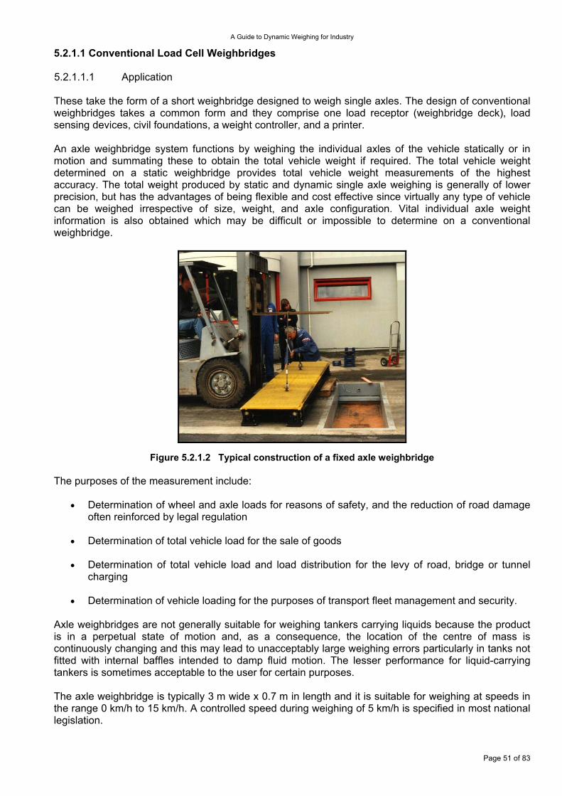
A Guide to Dynamic Weighing for Industry
5.2.1.1 Conventional Load Cell Weighbridges 5.2.1.1.1 Application These take the form of a short weighbridge designed to weigh single axles. The design of conventional weighbridges takes a common form and they comprise one load receptor (weighbridge deck), load sensing devices, civil foundations, a weight controller, and a printer. An axle weighbridge system functions by weighing the individual axles of the vehicle statically or in motion and summating these to obtain the total vehicle weight if required. The total vehicle weight determined on a static weighbridge provides total vehicle weight measurements of the highest accuracy. The total weight produced by static and dynamic single axle weighing is generally of lower precision, but has the advantages of being flexible and cost effective since virtually any type of vehicle can be weighed irrespective of size, weight, and axle configuration. Vital individual axle weight information is also obtained which may be difficult or impossible to determine on a conventional weighbridge.
Figure 5.2.1.2 Typical construction of a fixed axle weighbridge The purposes of the measurement include:
Determination of wheel and axle loads for reasons of safety, and the reduction of road damage often reinforced by legal regulation
•
•
•
•
Determination of total vehicle load for the sale of goods
Determination of total vehicle load and load distribution for the levy of road, bridge or tunnel charging
Determination of vehicle loading for the purposes of transport fleet management and security.
Axle weighbridges are not generally suitable for weighing tankers carrying liquids because the product is in a perpetual state of motion and, as a consequence, the location of the centre of mass is continuously changing and this may lead to unacceptably large weighing errors particularly in tanks not fitted with internal baffles intended to damp fluid motion. The lesser performance for liquid-carrying tankers is sometimes acceptable to the user for certain purposes. The axle weighbridge is typically 3 m wide x 0.7 m in length and it is suitable for weighing at speeds in the range 0 km/h to 15 km/h. A controlled speed during weighing of 5 km/h is specified in most national legislation.
Page 51 of 83
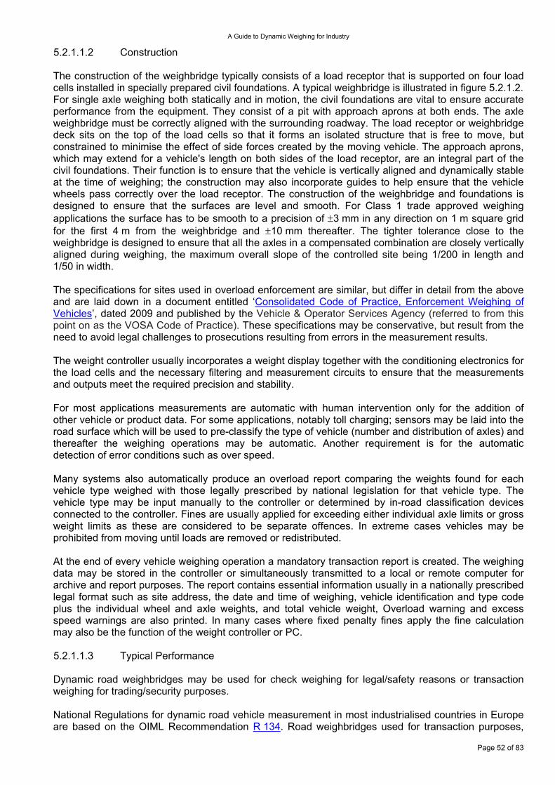
A Guide to Dynamic Weighing for Industry
5.2.1.1.2 Construction The construction of the weighbridge typically consists of a load receptor that is supported on four load cells installed in specially prepared civil foundations. A typical weighbridge is illustrated in figure 5.2.1.2. For single axle weighing both statically and in motion, the civil foundations are vital to ensure accurate performance from the equipment. They consist of a pit with approach aprons at both ends. The axle weighbridge must be correctly aligned with the surrounding roadway. The load receptor or weighbridge deck sits on the top of the load cells so that it forms an isolated structure that is free to move, but constrained to minimise the effect of side forces created by the moving vehicle. The approach aprons, which may extend for a vehicle's length on both sides of the load receptor, are an integral part of the civil foundations. Their function is to ensure that the vehicle is vertically aligned and dynamically stable at the time of weighing; the construction may also incorporate guides to help ensure that the vehicle wheels pass correctly over the load receptor. The construction of the weighbridge and foundations is designed to ensure that the surfaces are level and smooth. For Class 1 trade approved weighing applications the surface has to be smooth to a precision of ±3 mm in any direction on 1 m square grid for the first 4 m from the weighbridge and ±10 mm thereafter. The tighter tolerance close to the weighbridge is designed to ensure that all the axles in a compensated combination are closely vertically aligned during weighing, the maximum overall slope of the controlled site being 1/200 in length and 1/50 in width. The specifications for sites used in overload enforcement are similar, but differ in detail from the above and are laid down in a document entitled ‘Consolidated Code of Practice, Enforcement Weighing of Vehicles’, dated 2009 and published by the Vehicle & Operator Services Agency (referred to from this point on as the VOSA Code of Practice). These specifications may be conservative, but result from the need to avoid legal challenges to prosecutions resulting from errors in the measurement results. The weight controller usually incorporates a weight display together with the conditioning electronics for the load cells and the necessary filtering and measurement circuits to ensure that the measurements and outputs meet the required precision and stability. For most applications measurements are automatic with human intervention only for the addition of other vehicle or product data. For some applications, notably toll charging; sensors may be laid into the road surface which will be used to pre-classify the type of vehicle (number and distribution of axles) and thereafter the weighing operations may be automatic. Another requirement is for the automatic detection of error conditions such as over speed. Many systems also automatically produce an overload report comparing the weights found for each vehicle type weighed with those legally prescribed by national legislation for that vehicle type. The vehicle type may be input manually to the controller or determined by in-road classification devices connected to the controller. Fines are usually applied for exceeding either individual axle limits or gross weight limits as these are considered to be separate offences. In extreme cases vehicles may be prohibited from moving until loads are removed or redistributed. At the end of every vehicle weighing operation a mandatory transaction report is created. The weighing data may be stored in the controller or simultaneously transmitted to a local or remote computer for archive and report purposes. The report contains essential information usually in a nationally prescribed legal format such as site address, the date and time of weighing, vehicle identification and type code plus the individual wheel and axle weights, and total vehicle weight, Overload warning and excess speed warnings are also printed. In many cases where fixed penalty fines apply the fine calculation may also be the function of the weight controller or PC. 5.2.1.1.3 Typical Performance Dynamic road weighbridges may be used for check weighing for legal/safety reasons or transaction weighing for trading/security purposes. National Regulations for dynamic road vehicle measurement in most industrialised countries in Europe are based on the OIML Recommendation R 134. Road weighbridges used for transaction purposes,
Page 52 of 83
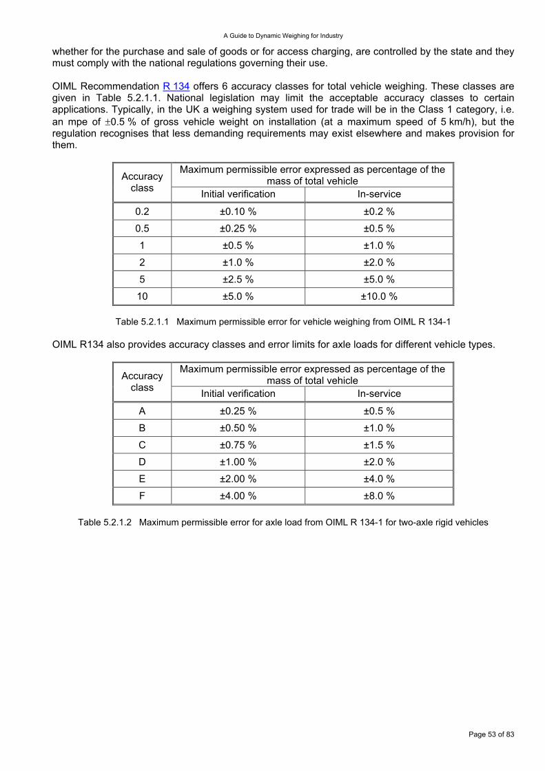
A Guide to Dynamic Weighing for Industry
whether for the purchase and sale of goods or for access charging, are controlled by the state and they must comply with the national regulations governing their use. OIML Recommendation R 134 offers 6 accuracy classes for total vehicle weighing. These classes are given in Table 5.2.1.1. National legislation may limit the acceptable accuracy classes to certain applications. Typically, in the UK a weighing system used for trade will be in the Class 1 category, i.e. an mpe of ±0.5 % of gross vehicle weight on installation (at a maximum speed of 5 km/h), but the regulation recognises that less demanding requirements may exist elsewhere and makes provision for them.
Maximum permissible error expressed as percentage of the mass of total vehicle Accuracy
class Initial verification In-service
0.2 ±0.10 % ±0.2 %
0.5 ±0.25 % ±0.5 %
1 ±0.5 % ±1.0 %
2 ±1.0 % ±2.0 %
5 ±2.5 % ±5.0 %
10 ±5.0 % ±10.0 %
Table 5.2.1.1 Maximum permissible error for vehicle weighing from OIML R 134-1 OIML R134 also provides accuracy classes and error limits for axle loads for different vehicle types.
Maximum permissible error expressed as percentage of the mass of total vehicle Accuracy
class Initial verification In-service
A ±0.25 % ±0.5 %
B ±0.50 % ±1.0 %
C ±0.75 % ±1.5 %
D ±1.00 % ±2.0 %
E ±2.00 % ±4.0 %
F ±4.00 % ±8.0 %
Table 5.2.1.2 Maximum permissible error for axle load from OIML R 134-1 for two-axle rigid vehicles
Page 53 of 83
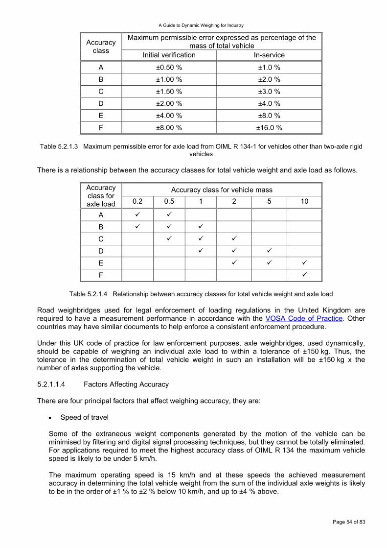
A Guide to Dynamic Weighing for Industry
Maximum permissible error expressed as percentage of the mass of total vehicle Accuracy
class Initial verification In-service
A ±0.50 % ±1.0 %
B ±1.00 % ±2.0 %
C ±1.50 % ±3.0 %
D ±2.00 % ±4.0 %
E ±4.00 % ±8.0 %
F ±8.00 % ±16.0 % Table 5.2.1.3 Maximum permissible error for axle load from OIML R 134-1 for vehicles other than two-axle rigid
vehicles There is a relationship between the accuracy classes for total vehicle weight and axle load as follows.
Accuracy class for vehicle mass Accuracy class for axle load 0.2 0.5 1 2 5 10
A
B
C
D
E
F
Table 5.2.1.4 Relationship between accuracy classes for total vehicle weight and axle load Road weighbridges used for legal enforcement of loading regulations in the United Kingdom are required to have a measurement performance in accordance with the VOSA Code of Practice. Other countries may have similar documents to help enforce a consistent enforcement procedure. Under this UK code of practice for law enforcement purposes, axle weighbridges, used dynamically, should be capable of weighing an individual axle load to within a tolerance of ±150 kg. Thus, the tolerance in the determination of total vehicle weight in such an installation will be ±150 kg x the number of axles supporting the vehicle. 5.2.1.1.4 Factors Affecting Accuracy There are four principal factors that affect weighing accuracy, they are:
Speed of travel •
Some of the extraneous weight components generated by the motion of the vehicle can be minimised by filtering and digital signal processing techniques, but they cannot be totally eliminated. For applications required to meet the highest accuracy class of OIML R 134 the maximum vehicle speed is likely to be under 5 km/h. The maximum operating speed is 15 km/h and at these speeds the achieved measurement accuracy in determining the total vehicle weight from the sum of the individual axle weights is likely to be in the order of ±1 % to ±2 % below 10 km/h, and up to ±4 % above.
Page 54 of 83
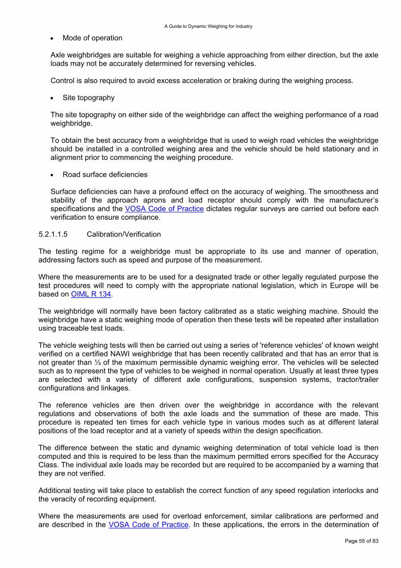
A Guide to Dynamic Weighing for Industry
Mode of operation •
•
•
Axle weighbridges are suitable for weighing a vehicle approaching from either direction, but the axle loads may not be accurately determined for reversing vehicles. Control is also required to avoid excess acceleration or braking during the weighing process.
Site topography
The site topography on either side of the weighbridge can affect the weighing performance of a road weighbridge. To obtain the best accuracy from a weighbridge that is used to weigh road vehicles the weighbridge should be installed in a controlled weighing area and the vehicle should be held stationary and in alignment prior to commencing the weighing procedure.
Road surface deficiencies
Surface deficiencies can have a profound effect on the accuracy of weighing. The smoothness and stability of the approach aprons and load receptor should comply with the manufacturer’s specifications and the VOSA Code of Practice dictates regular surveys are carried out before each verification to ensure compliance.
5.2.1.1.5 Calibration/Verification The testing regime for a weighbridge must be appropriate to its use and manner of operation, addressing factors such as speed and purpose of the measurement. Where the measurements are to be used for a designated trade or other legally regulated purpose the test procedures will need to comply with the appropriate national legislation, which in Europe will be based on OIML R 134. The weighbridge will normally have been factory calibrated as a static weighing machine. Should the weighbridge have a static weighing mode of operation then these tests will be repeated after installation using traceable test loads. The vehicle weighing tests will then be carried out using a series of 'reference vehicles' of known weight verified on a certified NAWI weighbridge that has been recently calibrated and that has an error that is not greater than ⅓ of the maximum permissible dynamic weighing error. The vehicles will be selected such as to represent the type of vehicles to be weighed in normal operation. Usually at least three types are selected with a variety of different axle configurations, suspension systems, tractor/trailer configurations and linkages. The reference vehicles are then driven over the weighbridge in accordance with the relevant regulations and observations of both the axle loads and the summation of these are made. This procedure is repeated ten times for each vehicle type in various modes such as at different lateral positions of the load receptor and at a variety of speeds within the design specification. The difference between the static and dynamic weighing determination of total vehicle load is then computed and this is required to be less than the maximum permitted errors specified for the Accuracy Class. The individual axle loads may be recorded but are required to be accompanied by a warning that they are not verified. Additional testing will take place to establish the correct function of any speed regulation interlocks and the veracity of recording equipment. Where the measurements are used for overload enforcement, similar calibrations are performed and are described in the VOSA Code of Practice. In these applications, the errors in the determination of
Page 55 of 83
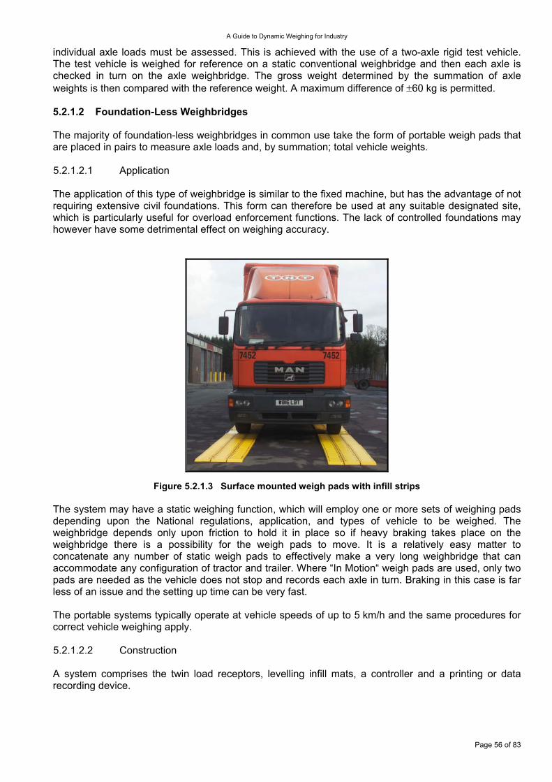
A Guide to Dynamic Weighing for Industry
individual axle loads must be assessed. This is achieved with the use of a two-axle rigid test vehicle. The test vehicle is weighed for reference on a static conventional weighbridge and then each axle is checked in turn on the axle weighbridge. The gross weight determined by the summation of axle weights is then compared with the reference weight. A maximum difference of ±60 kg is permitted. 5.2.1.2 Foundation-Less Weighbridges The majority of foundation-less weighbridges in common use take the form of portable weigh pads that are placed in pairs to measure axle loads and, by summation; total vehicle weights. 5.2.1.2.1 Application The application of this type of weighbridge is similar to the fixed machine, but has the advantage of not requiring extensive civil foundations. This form can therefore be used at any suitable designated site, which is particularly useful for overload enforcement functions. The lack of controlled foundations may however have some detrimental effect on weighing accuracy.
Figure 5.2.1.3 Surface mounted weigh pads with infill strips The system may have a static weighing function, which will employ one or more sets of weighing pads depending upon the National regulations, application, and types of vehicle to be weighed. The weighbridge depends only upon friction to hold it in place so if heavy braking takes place on the weighbridge there is a possibility for the weigh pads to move. It is a relatively easy matter to concatenate any number of static weigh pads to effectively make a very long weighbridge that can accommodate any configuration of tractor and trailer. Where “In Motion“ weigh pads are used, only two pads are needed as the vehicle does not stop and records each axle in turn. Braking in this case is far less of an issue and the setting up time can be very fast. The portable systems typically operate at vehicle speeds of up to 5 km/h and the same procedures for correct vehicle weighing apply. 5.2.1.2.2 Construction A system comprises the twin load receptors, levelling infill mats, a controller and a printing or data recording device.
Page 56 of 83
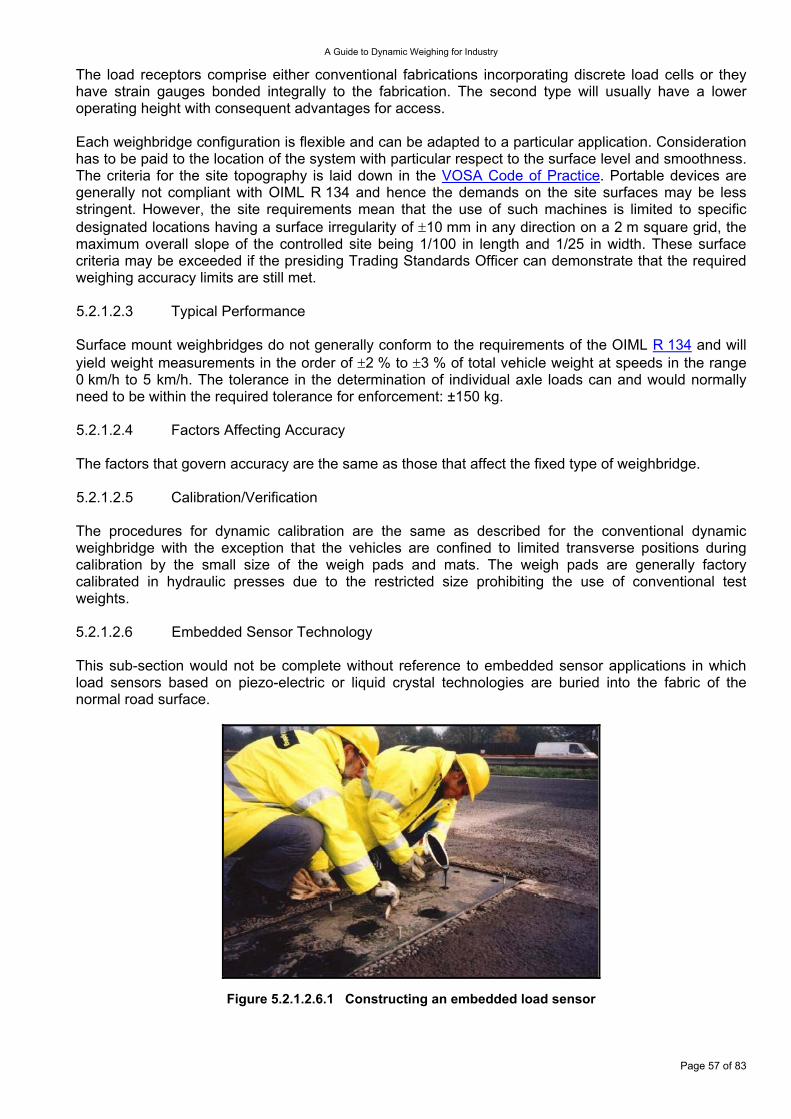
A Guide to Dynamic Weighing for Industry
The load receptors comprise either conventional fabrications incorporating discrete load cells or they have strain gauges bonded integrally to the fabrication. The second type will usually have a lower operating height with consequent advantages for access. Each weighbridge configuration is flexible and can be adapted to a particular application. Consideration has to be paid to the location of the system with particular respect to the surface level and smoothness. The criteria for the site topography is laid down in the VOSA Code of Practice. Portable devices are generally not compliant with OIML R 134 and hence the demands on the site surfaces may be less stringent. However, the site requirements mean that the use of such machines is limited to specific designated locations having a surface irregularity of ±10 mm in any direction on a 2 m square grid, the maximum overall slope of the controlled site being 1/100 in length and 1/25 in width. These surface criteria may be exceeded if the presiding Trading Standards Officer can demonstrate that the required weighing accuracy limits are still met. 5.2.1.2.3 Typical Performance Surface mount weighbridges do not generally conform to the requirements of the OIML R 134 and will yield weight measurements in the order of ±2 % to ±3 % of total vehicle weight at speeds in the range 0 km/h to 5 km/h. The tolerance in the determination of individual axle loads can and would normally need to be within the required tolerance for enforcement: ±150 kg. 5.2.1.2.4 Factors Affecting Accuracy The factors that govern accuracy are the same as those that affect the fixed type of weighbridge. 5.2.1.2.5 Calibration/Verification The procedures for dynamic calibration are the same as described for the conventional dynamic weighbridge with the exception that the vehicles are confined to limited transverse positions during calibration by the small size of the weigh pads and mats. The weigh pads are generally factory calibrated in hydraulic presses due to the restricted size prohibiting the use of conventional test weights. 5.2.1.2.6 Embedded Sensor Technology This sub-section would not be complete without reference to embedded sensor applications in which load sensors based on piezo-electric or liquid crystal technologies are buried into the fabric of the normal road surface.
Figure 5.2.1.2.6.1 Constructing an embedded load sensor
Page 57 of 83
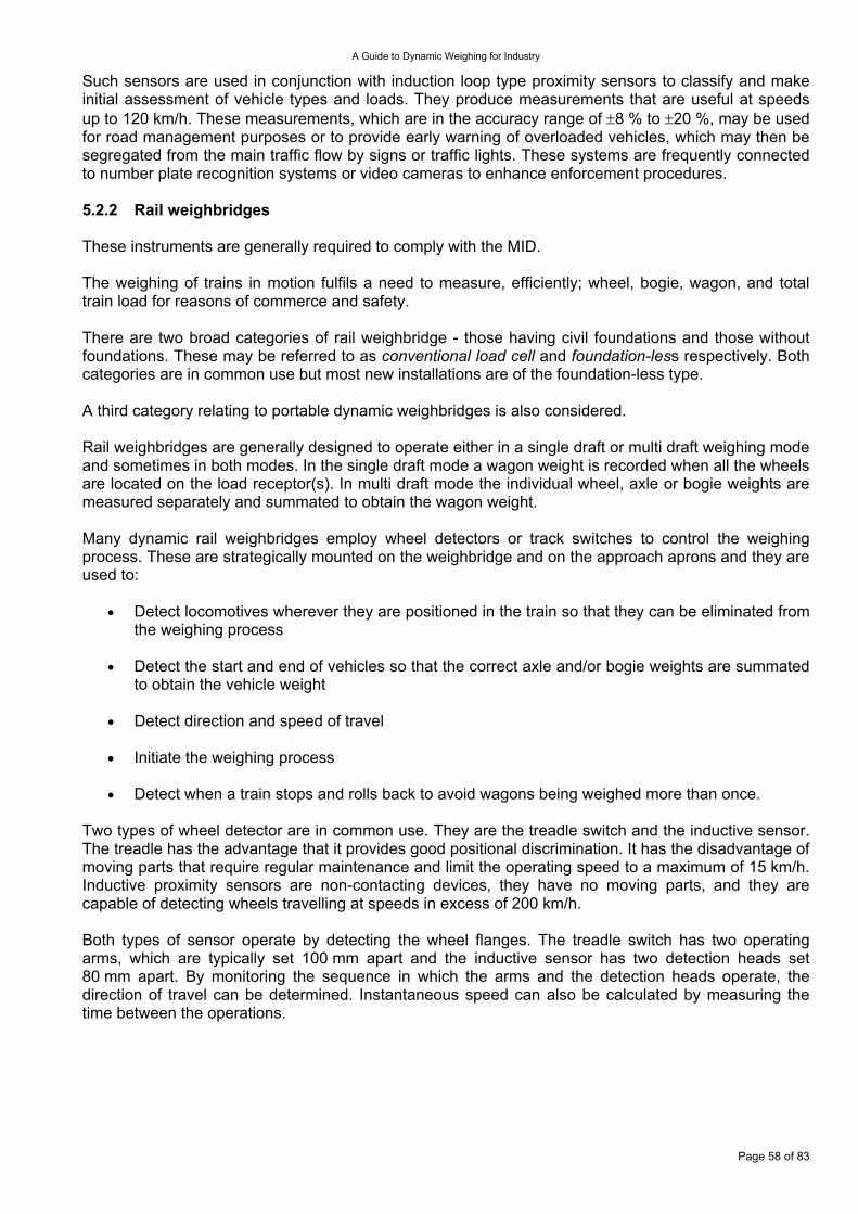
A Guide to Dynamic Weighing for Industry
Such sensors are used in conjunction with induction loop type proximity sensors to classify and make initial assessment of vehicle types and loads. They produce measurements that are useful at speeds up to 120 km/h. These measurements, which are in the accuracy range of ±8 % to ±20 %, may be used for road management purposes or to provide early warning of overloaded vehicles, which may then be segregated from the main traffic flow by signs or traffic lights. These systems are frequently connected to number plate recognition systems or video cameras to enhance enforcement procedures. 5.2.2 Rail weighbridges These instruments are generally required to comply with the MID. The weighing of trains in motion fulfils a need to measure, efficiently; wheel, bogie, wagon, and total train load for reasons of commerce and safety. There are two broad categories of rail weighbridge - those having civil foundations and those without foundations. These may be referred to as conventional load cell and foundation-less respectively. Both categories are in common use but most new installations are of the foundation-less type. A third category relating to portable dynamic weighbridges is also considered. Rail weighbridges are generally designed to operate either in a single draft or multi draft weighing mode and sometimes in both modes. In the single draft mode a wagon weight is recorded when all the wheels are located on the load receptor(s). In multi draft mode the individual wheel, axle or bogie weights are measured separately and summated to obtain the wagon weight. Many dynamic rail weighbridges employ wheel detectors or track switches to control the weighing process. These are strategically mounted on the weighbridge and on the approach aprons and they are used to:
Detect locomotives wherever they are positioned in the train so that they can be eliminated from the weighing process
•
•
•
•
•
Detect the start and end of vehicles so that the correct axle and/or bogie weights are summated to obtain the vehicle weight
Detect direction and speed of travel
Initiate the weighing process
Detect when a train stops and rolls back to avoid wagons being weighed more than once.
Two types of wheel detector are in common use. They are the treadle switch and the inductive sensor. The treadle has the advantage that it provides good positional discrimination. It has the disadvantage of moving parts that require regular maintenance and limit the operating speed to a maximum of 15 km/h. Inductive proximity sensors are non-contacting devices, they have no moving parts, and they are capable of detecting wheels travelling at speeds in excess of 200 km/h. Both types of sensor operate by detecting the wheel flanges. The treadle switch has two operating arms, which are typically set 100 mm apart and the inductive sensor has two detection heads set 80 mm apart. By monitoring the sequence in which the arms and the detection heads operate, the direction of travel can be determined. Instantaneous speed can also be calculated by measuring the time between the operations.
Page 58 of 83
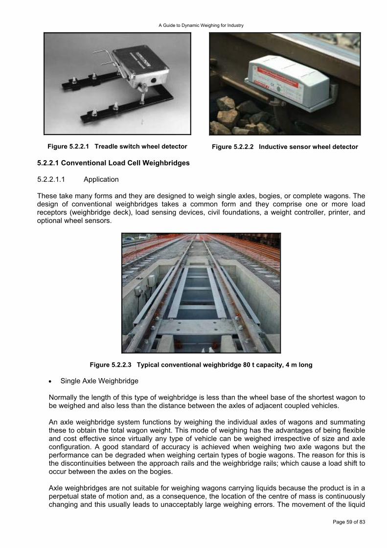
A Guide to Dynamic Weighing for Industry
Figure 5.2.2.1 Treadle switch wheel detector
Figure 5.2.2.2 Inductive sensor wheel detector 5.2.2.1 Conventional Load Cell Weighbridges 5.2.2.1.1 Application These take many forms and they are designed to weigh single axles, bogies, or complete wagons. The design of conventional weighbridges takes a common form and they comprise one or more load receptors (weighbridge deck), load sensing devices, civil foundations, a weight controller, printer, and optional wheel sensors.
Figure 5.2.2.3 Typical conventional weighbridge 80 t capacity, 4 m long
Single Axle Weighbridge •
Normally the length of this type of weighbridge is less than the wheel base of the shortest wagon to be weighed and also less than the distance between the axles of adjacent coupled vehicles. An axle weighbridge system functions by weighing the individual axles of wagons and summating these to obtain the total wagon weight. This mode of weighing has the advantages of being flexible and cost effective since virtually any type of vehicle can be weighed irrespective of size and axle configuration. A good standard of accuracy is achieved when weighing two axle wagons but the performance can be degraded when weighing certain types of bogie wagons. The reason for this is the discontinuities between the approach rails and the weighbridge rails; which cause a load shift to occur between the axles on the bogies. Axle weighbridges are not suitable for weighing wagons carrying liquids because the product is in a perpetual state of motion and, as a consequence, the location of the centre of mass is continuously changing and this usually leads to unacceptably large weighing errors. The movement of the liquid
Page 59 of 83
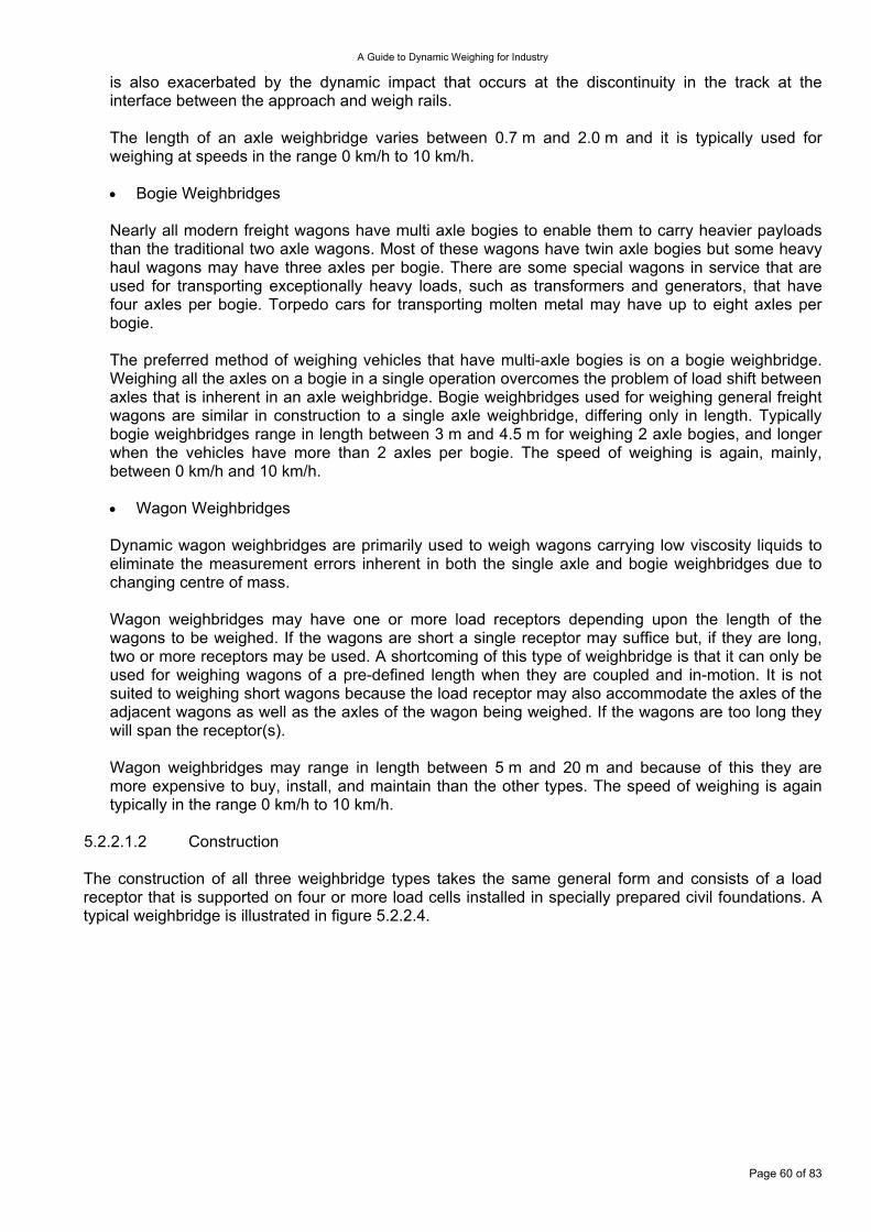
A Guide to Dynamic Weighing for Industry
is also exacerbated by the dynamic impact that occurs at the discontinuity in the track at the interface between the approach and weigh rails. The length of an axle weighbridge varies between 0.7 m and 2.0 m and it is typically used for weighing at speeds in the range 0 km/h to 10 km/h.
Bogie Weighbridges •
•
Nearly all modern freight wagons have multi axle bogies to enable them to carry heavier payloads than the traditional two axle wagons. Most of these wagons have twin axle bogies but some heavy haul wagons may have three axles per bogie. There are some special wagons in service that are used for transporting exceptionally heavy loads, such as transformers and generators, that have four axles per bogie. Torpedo cars for transporting molten metal may have up to eight axles per bogie. The preferred method of weighing vehicles that have multi-axle bogies is on a bogie weighbridge. Weighing all the axles on a bogie in a single operation overcomes the problem of load shift between axles that is inherent in an axle weighbridge. Bogie weighbridges used for weighing general freight wagons are similar in construction to a single axle weighbridge, differing only in length. Typically bogie weighbridges range in length between 3 m and 4.5 m for weighing 2 axle bogies, and longer when the vehicles have more than 2 axles per bogie. The speed of weighing is again, mainly, between 0 km/h and 10 km/h.
Wagon Weighbridges
Dynamic wagon weighbridges are primarily used to weigh wagons carrying low viscosity liquids to eliminate the measurement errors inherent in both the single axle and bogie weighbridges due to changing centre of mass. Wagon weighbridges may have one or more load receptors depending upon the length of the wagons to be weighed. If the wagons are short a single receptor may suffice but, if they are long, two or more receptors may be used. A shortcoming of this type of weighbridge is that it can only be used for weighing wagons of a pre-defined length when they are coupled and in-motion. It is not suited to weighing short wagons because the load receptor may also accommodate the axles of the adjacent wagons as well as the axles of the wagon being weighed. If the wagons are too long they will span the receptor(s). Wagon weighbridges may range in length between 5 m and 20 m and because of this they are more expensive to buy, install, and maintain than the other types. The speed of weighing is again typically in the range 0 km/h to 10 km/h.
5.2.2.1.2 Construction The construction of all three weighbridge types takes the same general form and consists of a load receptor that is supported on four or more load cells installed in specially prepared civil foundations. A typical weighbridge is illustrated in figure 5.2.2.4.
Page 60 of 83
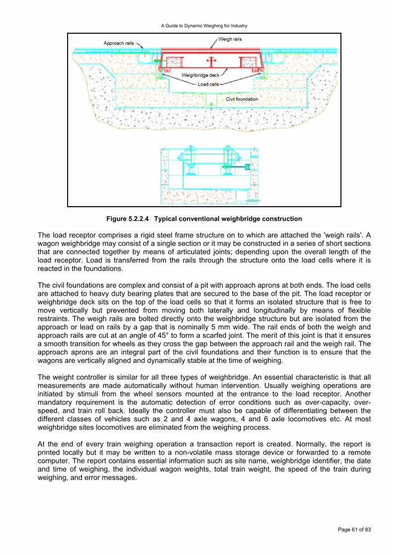
A Guide to Dynamic Weighing for Industry
Figure 5.2.2.4 Typical conventional weighbridge construction The load receptor comprises a rigid steel frame structure on to which are attached the 'weigh rails'. A wagon weighbridge may consist of a single section or it may be constructed in a series of short sections that are connected together by means of articulated joints; depending upon the overall length of the load receptor. Load is transferred from the rails through the structure onto the load cells where it is reacted in the foundations. The civil foundations are complex and consist of a pit with approach aprons at both ends. The load cells are attached to heavy duty bearing plates that are secured to the base of the pit. The load receptor or weighbridge deck sits on the top of the load cells so that it forms an isolated structure that is free to move vertically but prevented from moving both laterally and longitudinally by means of flexible restraints. The weigh rails are bolted directly onto the weighbridge structure but are isolated from the approach or lead on rails by a gap that is nominally 5 mm wide. The rail ends of both the weigh and approach rails are cut at an angle of 45° to form a scarfed joint. The merit of this joint is that it ensures a smooth transition for wheels as they cross the gap between the approach rail and the weigh rail. The approach aprons are an integral part of the civil foundations and their function is to ensure that the wagons are vertically aligned and dynamically stable at the time of weighing. The weight controller is similar for all three types of weighbridge. An essential characteristic is that all measurements are made automatically without human intervention. Usually weighing operations are initiated by stimuli from the wheel sensors mounted at the entrance to the load receptor. Another mandatory requirement is the automatic detection of error conditions such as over-capacity, over-speed, and train roll back. Ideally the controller must also be capable of differentiating between the different classes of vehicles such as 2 and 4 axle wagons, 4 and 6 axle locomotives etc. At most weighbridge sites locomotives are eliminated from the weighing process. At the end of every train weighing operation a transaction report is created. Normally, the report is printed locally but it may be written to a non-volatile mass storage device or forwarded to a remote computer. The report contains essential information such as site name, weighbridge identifier, the date and time of weighing, the individual wagon weights, total train weight, the speed of the train during weighing, and error messages.
Page 61 of 83
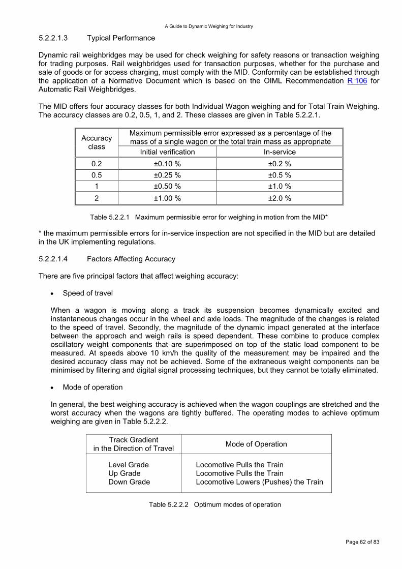
A Guide to Dynamic Weighing for Industry
5.2.2.1.3 Typical Performance Dynamic rail weighbridges may be used for check weighing for safety reasons or transaction weighing for trading purposes. Rail weighbridges used for transaction purposes, whether for the purchase and sale of goods or for access charging, must comply with the MID. Conformity can be established through the application of a Normative Document which is based on the OIML Recommendation R 106 for Automatic Rail Weighbridges. The MID offers four accuracy classes for both Individual Wagon weighing and for Total Train Weighing. The accuracy classes are 0.2, 0.5, 1, and 2. These classes are given in Table 5.2.2.1.
Maximum permissible error expressed as a percentage of the mass of a single wagon or the total train mass as appropriate Accuracy
class Initial verification In-service
0.2 ±0.10 % ±0.2 % 0.5 ±0.25 % ±0.5 % 1 ±0.50 % ±1.0 % 2 ±1.00 % ±2.0 %
Table 5.2.2.1 Maximum permissible error for weighing in motion from the MID*
* the maximum permissible errors for in-service inspection are not specified in the MID but are detailed in the UK implementing regulations. 5.2.2.1.4 Factors Affecting Accuracy There are five principal factors that affect weighing accuracy:
Speed of travel •
•
When a wagon is moving along a track its suspension becomes dynamically excited and instantaneous changes occur in the wheel and axle loads. The magnitude of the changes is related to the speed of travel. Secondly, the magnitude of the dynamic impact generated at the interface between the approach and weigh rails is speed dependent. These combine to produce complex oscillatory weight components that are superimposed on top of the static load component to be measured. At speeds above 10 km/h the quality of the measurement may be impaired and the desired accuracy class may not be achieved. Some of the extraneous weight components can be minimised by filtering and digital signal processing techniques, but they cannot be totally eliminated.
Mode of operation
In general, the best weighing accuracy is achieved when the wagon couplings are stretched and the worst accuracy when the wagons are tightly buffered. The operating modes to achieve optimum weighing are given in Table 5.2.2.2.
Track Gradient in the Direction of Travel Mode of Operation
Level Grade Up Grade Down Grade
Locomotive Pulls the Train Locomotive Pulls the Train Locomotive Lowers (Pushes) the Train
Table 5.2.2.2 Optimum modes of operation
Page 62 of 83
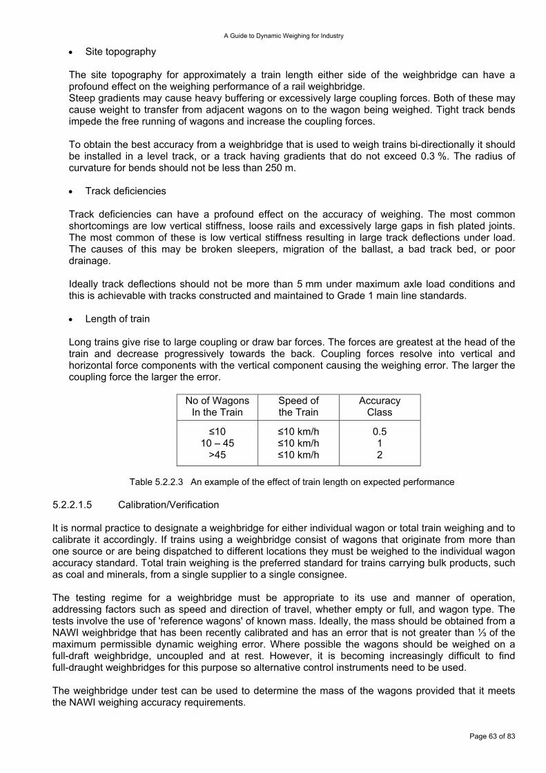
A Guide to Dynamic Weighing for Industry
Site topography •
•
•
The site topography for approximately a train length either side of the weighbridge can have a profound effect on the weighing performance of a rail weighbridge. Steep gradients may cause heavy buffering or excessively large coupling forces. Both of these may cause weight to transfer from adjacent wagons on to the wagon being weighed. Tight track bends impede the free running of wagons and increase the coupling forces. To obtain the best accuracy from a weighbridge that is used to weigh trains bi-directionally it should be installed in a level track, or a track having gradients that do not exceed 0.3 %. The radius of curvature for bends should not be less than 250 m.
Track deficiencies
Track deficiencies can have a profound effect on the accuracy of weighing. The most common shortcomings are low vertical stiffness, loose rails and excessively large gaps in fish plated joints. The most common of these is low vertical stiffness resulting in large track deflections under load. The causes of this may be broken sleepers, migration of the ballast, a bad track bed, or poor drainage. Ideally track deflections should not be more than 5 mm under maximum axle load conditions and this is achievable with tracks constructed and maintained to Grade 1 main line standards.
Length of train
Long trains give rise to large coupling or draw bar forces. The forces are greatest at the head of the train and decrease progressively towards the back. Coupling forces resolve into vertical and horizontal force components with the vertical component causing the weighing error. The larger the coupling force the larger the error.
No of Wagons In the Train
Speed of the Train
Accuracy Class
≤10 10 – 45
>45
≤10 km/h ≤10 km/h ≤10 km/h
0.5 1 2
Table 5.2.2.3 An example of the effect of train length on expected performance
5.2.2.1.5 Calibration/Verification It is normal practice to designate a weighbridge for either individual wagon or total train weighing and to calibrate it accordingly. If trains using a weighbridge consist of wagons that originate from more than one source or are being dispatched to different locations they must be weighed to the individual wagon accuracy standard. Total train weighing is the preferred standard for trains carrying bulk products, such as coal and minerals, from a single supplier to a single consignee. The testing regime for a weighbridge must be appropriate to its use and manner of operation, addressing factors such as speed and direction of travel, whether empty or full, and wagon type. The tests involve the use of 'reference wagons' of known mass. Ideally, the mass should be obtained from a NAWI weighbridge that has been recently calibrated and has an error that is not greater than ⅓ of the maximum permissible dynamic weighing error. Where possible the wagons should be weighed on a full-draft weighbridge, uncoupled and at rest. However, it is becoming increasingly difficult to find full-draught weighbridges for this purpose so alternative control instruments need to be used. The weighbridge under test can be used to determine the mass of the wagons provided that it meets the NAWI weighing accuracy requirements.
Page 63 of 83
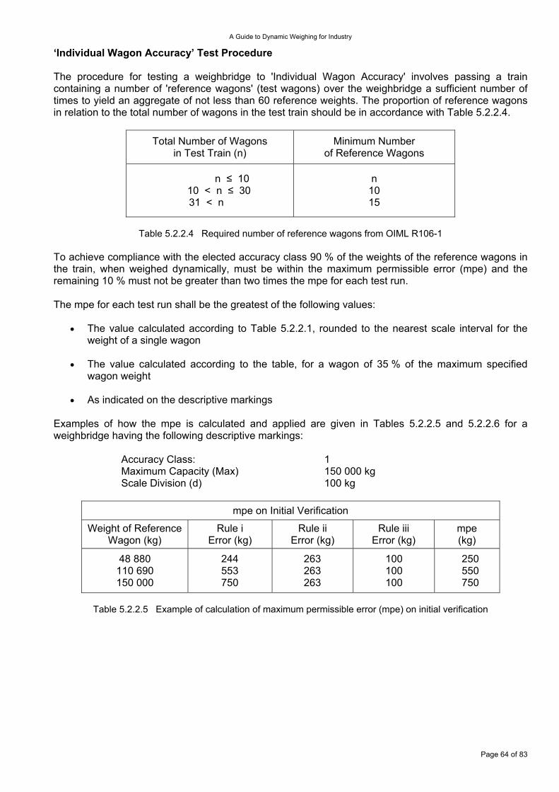
A Guide to Dynamic Weighing for Industry
‘Individual Wagon Accuracy’ Test Procedure The procedure for testing a weighbridge to 'Individual Wagon Accuracy' involves passing a train containing a number of 'reference wagons' (test wagons) over the weighbridge a sufficient number of times to yield an aggregate of not less than 60 reference weights. The proportion of reference wagons in relation to the total number of wagons in the test train should be in accordance with Table 5.2.2.4.
Total Number of Wagons in Test Train (n)
Minimum Number of Reference Wagons
n ≤ 10 10 < n ≤ 30 31 < n
n 10 15
Table 5.2.2.4 Required number of reference wagons from OIML R106-1
To achieve compliance with the elected accuracy class 90 % of the weights of the reference wagons in the train, when weighed dynamically, must be within the maximum permissible error (mpe) and the remaining 10 % must not be greater than two times the mpe for each test run. The mpe for each test run shall be the greatest of the following values:
The value calculated according to Table 5.2.2.1, rounded to the nearest scale interval for the weight of a single wagon
•
•
•
The value calculated according to the table, for a wagon of 35 % of the maximum specified wagon weight
As indicated on the descriptive markings
Examples of how the mpe is calculated and applied are given in Tables 5.2.2.5 and 5.2.2.6 for a weighbridge having the following descriptive markings: Accuracy Class: 1 Maximum Capacity (Max) 150 000 kg Scale Division (d) 100 kg
mpe on Initial Verification
Weight of Reference Wagon (kg)
Rule i Error (kg)
Rule ii Error (kg)
Rule iii Error (kg)
mpe (kg)
48 880 110 690 150 000
244 553 750
263 263 263
100 100 100
250 550 750
Table 5.2.2.5 Example of calculation of maximum permissible error (mpe) on initial verification
Page 64 of 83
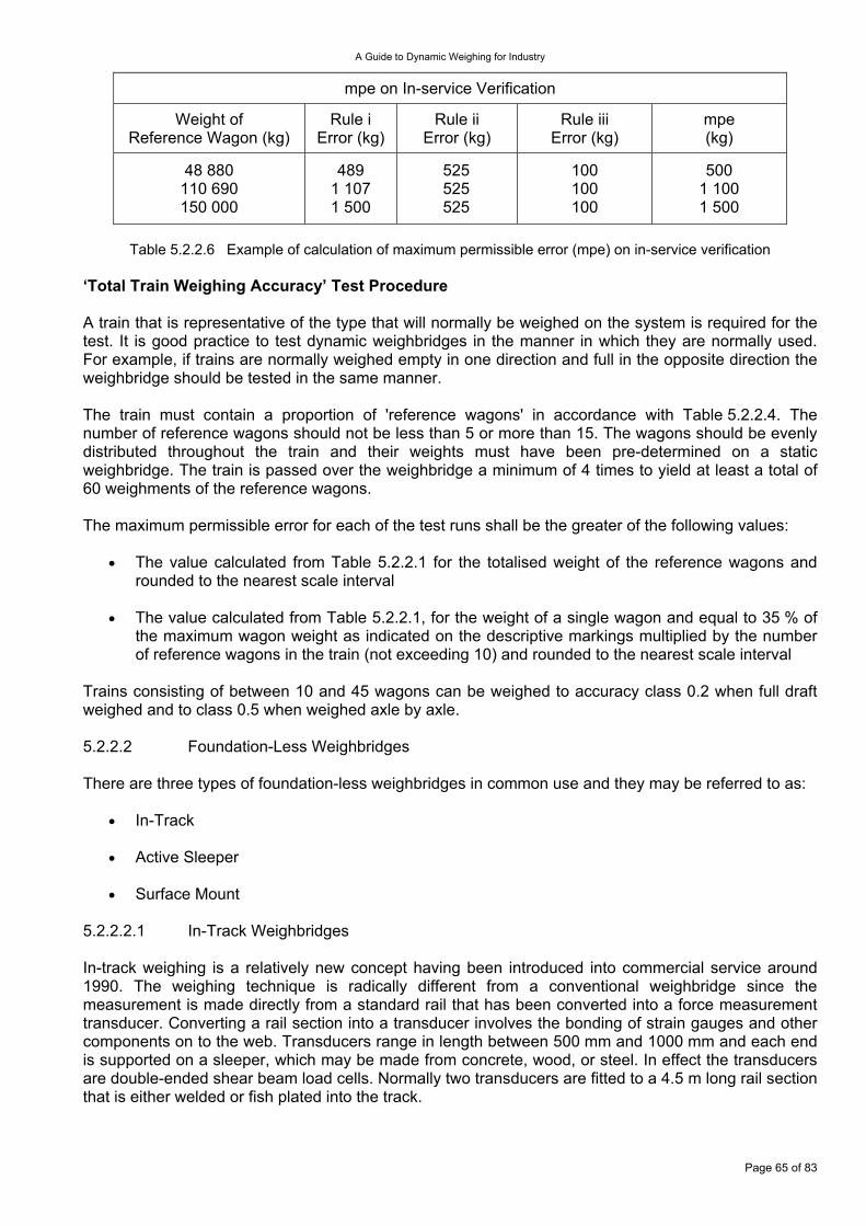
A Guide to Dynamic Weighing for Industry
mpe on In-service Verification
Weight of Reference Wagon (kg)
Rule i Error (kg)
Rule ii Error (kg)
Rule iii Error (kg)
mpe (kg)
48 880 110 690 150 000
489 1 107 1 500
525 525 525
100 100 100
500 1 100 1 500
Table 5.2.2.6 Example of calculation of maximum permissible error (mpe) on in-service verification
‘Total Train Weighing Accuracy’ Test Procedure A train that is representative of the type that will normally be weighed on the system is required for the test. It is good practice to test dynamic weighbridges in the manner in which they are normally used. For example, if trains are normally weighed empty in one direction and full in the opposite direction the weighbridge should be tested in the same manner. The train must contain a proportion of 'reference wagons' in accordance with Table 5.2.2.4. The number of reference wagons should not be less than 5 or more than 15. The wagons should be evenly distributed throughout the train and their weights must have been pre-determined on a static weighbridge. The train is passed over the weighbridge a minimum of 4 times to yield at least a total of 60 weighments of the reference wagons. The maximum permissible error for each of the test runs shall be the greater of the following values:
The value calculated from Table 5.2.2.1 for the totalised weight of the reference wagons and rounded to the nearest scale interval
•
•
•
•
•
The value calculated from Table 5.2.2.1, for the weight of a single wagon and equal to 35 % of the maximum wagon weight as indicated on the descriptive markings multiplied by the number of reference wagons in the train (not exceeding 10) and rounded to the nearest scale interval
Trains consisting of between 10 and 45 wagons can be weighed to accuracy class 0.2 when full draft weighed and to class 0.5 when weighed axle by axle. 5.2.2.2 Foundation-Less Weighbridges There are three types of foundation-less weighbridges in common use and they may be referred to as:
In-Track
Active Sleeper
Surface Mount 5.2.2.2.1 In-Track Weighbridges In-track weighing is a relatively new concept having been introduced into commercial service around 1990. The weighing technique is radically different from a conventional weighbridge since the measurement is made directly from a standard rail that has been converted into a force measurement transducer. Converting a rail section into a transducer involves the bonding of strain gauges and other components on to the web. Transducers range in length between 500 mm and 1000 mm and each end is supported on a sleeper, which may be made from concrete, wood, or steel. In effect the transducers are double-ended shear beam load cells. Normally two transducers are fitted to a 4.5 m long rail section that is either welded or fish plated into the track.
Page 65 of 83
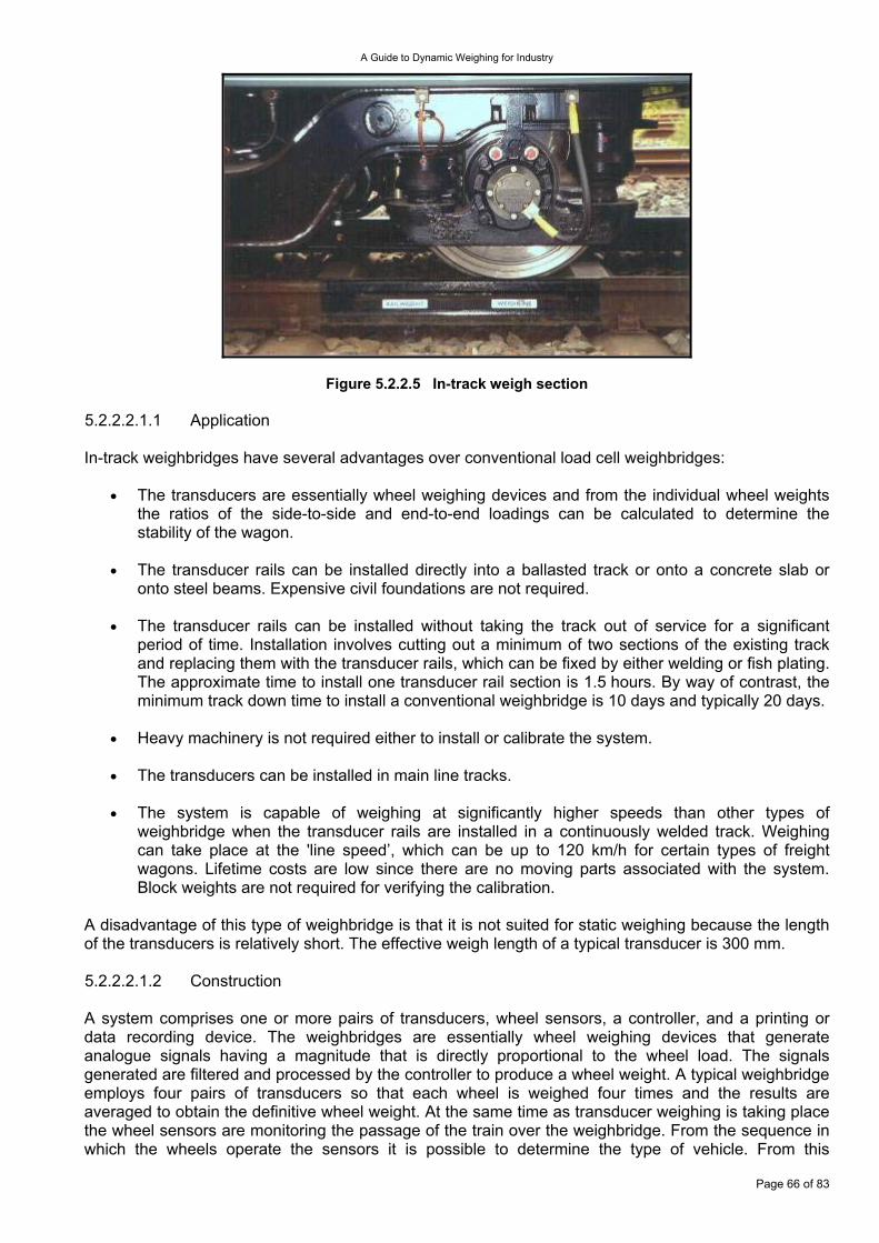
A Guide to Dynamic Weighing for Industry
Figure 5.2.2.5 In-track weigh section 5.2.2.2.1.1 Application In-track weighbridges have several advantages over conventional load cell weighbridges:
The transducers are essentially wheel weighing devices and from the individual wheel weights the ratios of the side-to-side and end-to-end loadings can be calculated to determine the stability of the wagon.
•
•
•
•
•
•
The transducer rails can be installed directly into a ballasted track or onto a concrete slab or onto steel beams. Expensive civil foundations are not required.
The transducer rails can be installed without taking the track out of service for a significant period of time. Installation involves cutting out a minimum of two sections of the existing track and replacing them with the transducer rails, which can be fixed by either welding or fish plating. The approximate time to install one transducer rail section is 1.5 hours. By way of contrast, the minimum track down time to install a conventional weighbridge is 10 days and typically 20 days.
Heavy machinery is not required either to install or calibrate the system.
The transducers can be installed in main line tracks.
The system is capable of weighing at significantly higher speeds than other types of weighbridge when the transducer rails are installed in a continuously welded track. Weighing can take place at the 'line speed’, which can be up to 120 km/h for certain types of freight wagons. Lifetime costs are low since there are no moving parts associated with the system. Block weights are not required for verifying the calibration.
A disadvantage of this type of weighbridge is that it is not suited for static weighing because the length of the transducers is relatively short. The effective weigh length of a typical transducer is 300 mm. 5.2.2.2.1.2 Construction A system comprises one or more pairs of transducers, wheel sensors, a controller, and a printing or data recording device. The weighbridges are essentially wheel weighing devices that generate analogue signals having a magnitude that is directly proportional to the wheel load. The signals generated are filtered and processed by the controller to produce a wheel weight. A typical weighbridge employs four pairs of transducers so that each wheel is weighed four times and the results are averaged to obtain the definitive wheel weight. At the same time as transducer weighing is taking place the wheel sensors are monitoring the passage of the train over the weighbridge. From the sequence in which the wheels operate the sensors it is possible to determine the type of vehicle. From this
Page 66 of 83
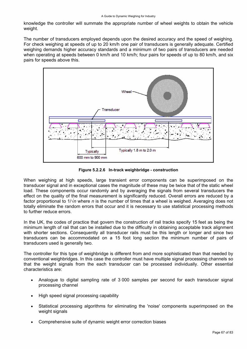
A Guide to Dynamic Weighing for Industry
knowledge the controller will summate the appropriate number of wheel weights to obtain the vehicle weight. The number of transducers employed depends upon the desired accuracy and the speed of weighing. For check weighing at speeds of up to 20 km/h one pair of transducers is generally adequate. Certified weighing demands higher accuracy standards and a minimum of two pairs of transducers are needed when operating at speeds between 0 km/h and 10 km/h; four pairs for speeds of up to 80 km/h, and six pairs for speeds above this.
Figure 5.2.2.6 In-track weighbridge - construction When weighing at high speeds, large transient error components can be superimposed on the transducer signal and in exceptional cases the magnitude of these may be twice that of the static wheel load. These components occur randomly and by averaging the signals from several transducers the effect on the quality of the final measurement is significantly reduced. Overall errors are reduced by a factor proportional to 1/√n where n is the number of times that a wheel is weighed. Averaging does not totally eliminate the random errors that occur and it is necessary to use statistical processing methods to further reduce errors. In the UK, the codes of practice that govern the construction of rail tracks specify 15 feet as being the minimum length of rail that can be installed due to the difficulty in obtaining acceptable track alignment with shorter sections. Consequently all transducer rails must be this length or longer and since two transducers can be accommodated on a 15 foot long section the minimum number of pairs of transducers used is generally two. The controller for this type of weighbridge is different from and more sophisticated than that needed by conventional weighbridges. In this case the controller must have multiple signal processing channels so that the weight signals from the each transducer can be processed individually. Other essential characteristics are:
Analogue to digital sampling rate of 3 000 samples per second for each transducer signal processing channel
•
•
•
•
High speed signal processing capability
Statistical processing algorithms for eliminating the 'noise' components superimposed on the weight signals
Comprehensive suite of dynamic weight error correction biases
Page 67 of 83
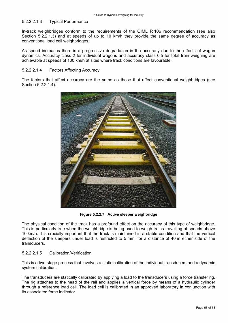
A Guide to Dynamic Weighing for Industry
5.2.2.2.1.3 Typical Performance In-track weighbridges conform to the requirements of the OIML R 106 recommendation (see also Section 5.2.2.1.3) and at speeds of up to 10 km/h they provide the same degree of accuracy as conventional load cell weighbridges. As speed increases there is a progressive degradation in the accuracy due to the effects of wagon dynamics. Accuracy class 2 for individual wagons and accuracy class 0.5 for total train weighing are achievable at speeds of 100 km/h at sites where track conditions are favourable. 5.2.2.2.1.4 Factors Affecting Accuracy The factors that affect accuracy are the same as those that affect conventional weighbridges (see Section 5.2.2.1.4).
Figure 5.2.2.7 Active sleeper weighbridge The physical condition of the track has a profound effect on the accuracy of this type of weighbridge. This is particularly true when the weighbridge is being used to weigh trains travelling at speeds above 10 km/h. It is crucially important that the track is maintained in a stable condition and that the vertical deflection of the sleepers under load is restricted to 5 mm, for a distance of 40 m either side of the transducers. 5.2.2.2.1.5 Calibration/Verification This is a two-stage process that involves a static calibration of the individual transducers and a dynamic system calibration. The transducers are statically calibrated by applying a load to the transducers using a force transfer rig. The rig attaches to the head of the rail and applies a vertical force by means of a hydraulic cylinder through a reference load cell. The load cell is calibrated in an approved laboratory in conjunction with its associated force indicator.
Page 68 of 83
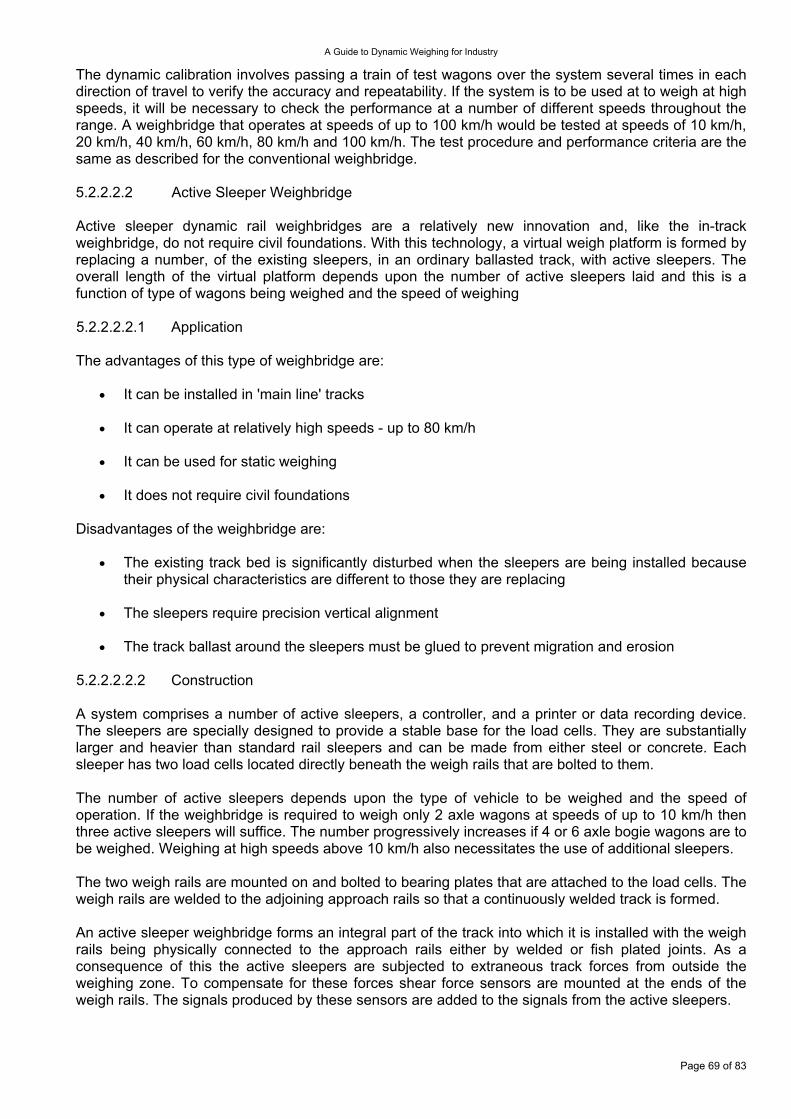
A Guide to Dynamic Weighing for Industry
The dynamic calibration involves passing a train of test wagons over the system several times in each direction of travel to verify the accuracy and repeatability. If the system is to be used at to weigh at high speeds, it will be necessary to check the performance at a number of different speeds throughout the range. A weighbridge that operates at speeds of up to 100 km/h would be tested at speeds of 10 km/h, 20 km/h, 40 km/h, 60 km/h, 80 km/h and 100 km/h. The test procedure and performance criteria are the same as described for the conventional weighbridge. 5.2.2.2.2 Active Sleeper Weighbridge Active sleeper dynamic rail weighbridges are a relatively new innovation and, like the in-track weighbridge, do not require civil foundations. With this technology, a virtual weigh platform is formed by replacing a number, of the existing sleepers, in an ordinary ballasted track, with active sleepers. The overall length of the virtual platform depends upon the number of active sleepers laid and this is a function of type of wagons being weighed and the speed of weighing 5.2.2.2.2.1 Application The advantages of this type of weighbridge are:
It can be installed in 'main line' tracks •
•
•
•
•
•
•
It can operate at relatively high speeds - up to 80 km/h
It can be used for static weighing
It does not require civil foundations
Disadvantages of the weighbridge are:
The existing track bed is significantly disturbed when the sleepers are being installed because their physical characteristics are different to those they are replacing
The sleepers require precision vertical alignment
The track ballast around the sleepers must be glued to prevent migration and erosion
5.2.2.2.2.2 Construction A system comprises a number of active sleepers, a controller, and a printer or data recording device. The sleepers are specially designed to provide a stable base for the load cells. They are substantially larger and heavier than standard rail sleepers and can be made from either steel or concrete. Each sleeper has two load cells located directly beneath the weigh rails that are bolted to them. The number of active sleepers depends upon the type of vehicle to be weighed and the speed of operation. If the weighbridge is required to weigh only 2 axle wagons at speeds of up to 10 km/h then three active sleepers will suffice. The number progressively increases if 4 or 6 axle bogie wagons are to be weighed. Weighing at high speeds above 10 km/h also necessitates the use of additional sleepers. The two weigh rails are mounted on and bolted to bearing plates that are attached to the load cells. The weigh rails are welded to the adjoining approach rails so that a continuously welded track is formed. An active sleeper weighbridge forms an integral part of the track into which it is installed with the weigh rails being physically connected to the approach rails either by welded or fish plated joints. As a consequence of this the active sleepers are subjected to extraneous track forces from outside the weighing zone. To compensate for these forces shear force sensors are mounted at the ends of the weigh rails. The signals produced by these sensors are added to the signals from the active sleepers.
Page 69 of 83
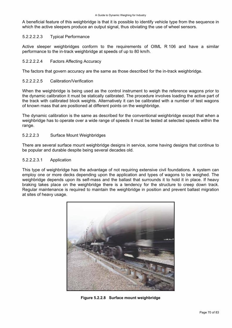
A Guide to Dynamic Weighing for Industry
A beneficial feature of this weighbridge is that it is possible to identify vehicle type from the sequence in which the active sleepers produce an output signal, thus obviating the use of wheel sensors. 5.2.2.2.2.3 Typical Performance Active sleeper weighbridges conform to the requirements of OIML R 106 and have a similar performance to the in-track weighbridge at speeds of up to 80 km/h. 5.2.2.2.2.4 Factors Affecting Accuracy The factors that govern accuracy are the same as those described for the in-track weighbridge. 5.2.2.2.2.5 Calibration/Verification When the weighbridge is being used as the control instrument to weigh the reference wagons prior to the dynamic calibration it must be statically calibrated. The procedure involves loading the active part of the track with calibrated block weights. Alternatively it can be calibrated with a number of test wagons of known mass that are positioned at different points on the weighbridge. The dynamic calibration is the same as described for the conventional weighbridge except that when a weighbridge has to operate over a wide range of speeds it must be tested at selected speeds within the range. 5.2.2.2.3 Surface Mount Weighbridges There are several surface mount weighbridge designs in service, some having designs that continue to be popular and durable despite being several decades old. 5.2.2.2.3.1 Application This type of weighbridge has the advantage of not requiring extensive civil foundations. A system can employ one or more decks depending upon the application and types of wagons to be weighed. The weighbridge depends upon its self-mass and the ballast that surrounds it to hold it in place. If heavy braking takes place on the weighbridge there is a tendency for the structure to creep down track. Regular maintenance is required to maintain the weighbridge in position and prevent ballast migration at sites of heavy usage.
Figure 5.2.2.8 Surface mount weighbridge
Page 70 of 83
A Guide to Dynamic Weighing for Industry
It is a relatively easy matter to concatenate up two or more structures to effectively make a very long weighbridge. This arrangement is ideally suited for the weighing of liquid carrying wagons in which the centre of gravity is constantly changing. The weighbridge can be operated bi-directionally but the nature of the design restricts the operating speed range to 0 km/h to 10 km/h. Running trains over the weighbridge at higher speeds will cause damage to the weigh rails, the structure, and the approach rails due to impact loading. 5.2.2.2.3.2 Construction A system comprises between one and three weighbridge structures, a controller, and a printing or data recording device. Each weighbridge construction is a ladder-like frame that is fabricated from heavy duty steel box sections. The structure is all welded; it is extremely rigid and has an overall length of between 8 m and 11 m. There are short (1.5 m) ‘lead on’ rail sections at both ends of the structure with the load receptor located in the central section. The load receptor is a 'floating' platform that is mounted on four high capacity shear beam load cells. As well as measuring load, the cells have the secondary function of acting as restraints to prevent lateral and longitudinal movement of the load receptor. Two weigh rails are bolted and clipped to the load receptor. There are 5 mm discontinuities between the weigh rails and the approach rails that are attached to the 'lead on' section of the structure. Installation is an involved procedure requiring the use of heavy plant and it includes the following activities:
Removing the existing track and sleepers •
•
•
•
•
•
Removing the existing top and bottom ballast layers
Levelling and compacting the sub ballast on which the structure is to rest
Lifting the weighbridge structure into place
Re-instating the top and bottom ballast around the structure and filling in the voids between the structure's longitudinal members
Installing and fixing the approach rails and sleepers and replacing ballast
Heavy duty plant is required for removing and re-instating the ballast and at least one high capacity crane is needed to lift the structures into position. 5.2.2.2.3.3 Typical Performance Surface mount weighbridges conform to the requirements of OIML R 106 and they meet accuracy class 0.5 and 0.25 for Individual Wagon and Total Train weighing respectively at speeds in the range 0 km/h to 10 km/h. 5.2.2.2.3.4 Factors Affecting Accuracy The factors that govern accuracy are the same as those that affect the other types of weighbridge. 5.2.2.2.3.5 Calibration/Verification When the weighbridge is being used as the control instrument to weigh the reference wagons, prior to the dynamic calibration, it must be statically calibrated. The procedure involves loading calibrated block weights on to the load receptor Alternatively it can be calibrated with a number of test wagons of known mass that are positioned at different points on the load receptor.
Page 71 of 83
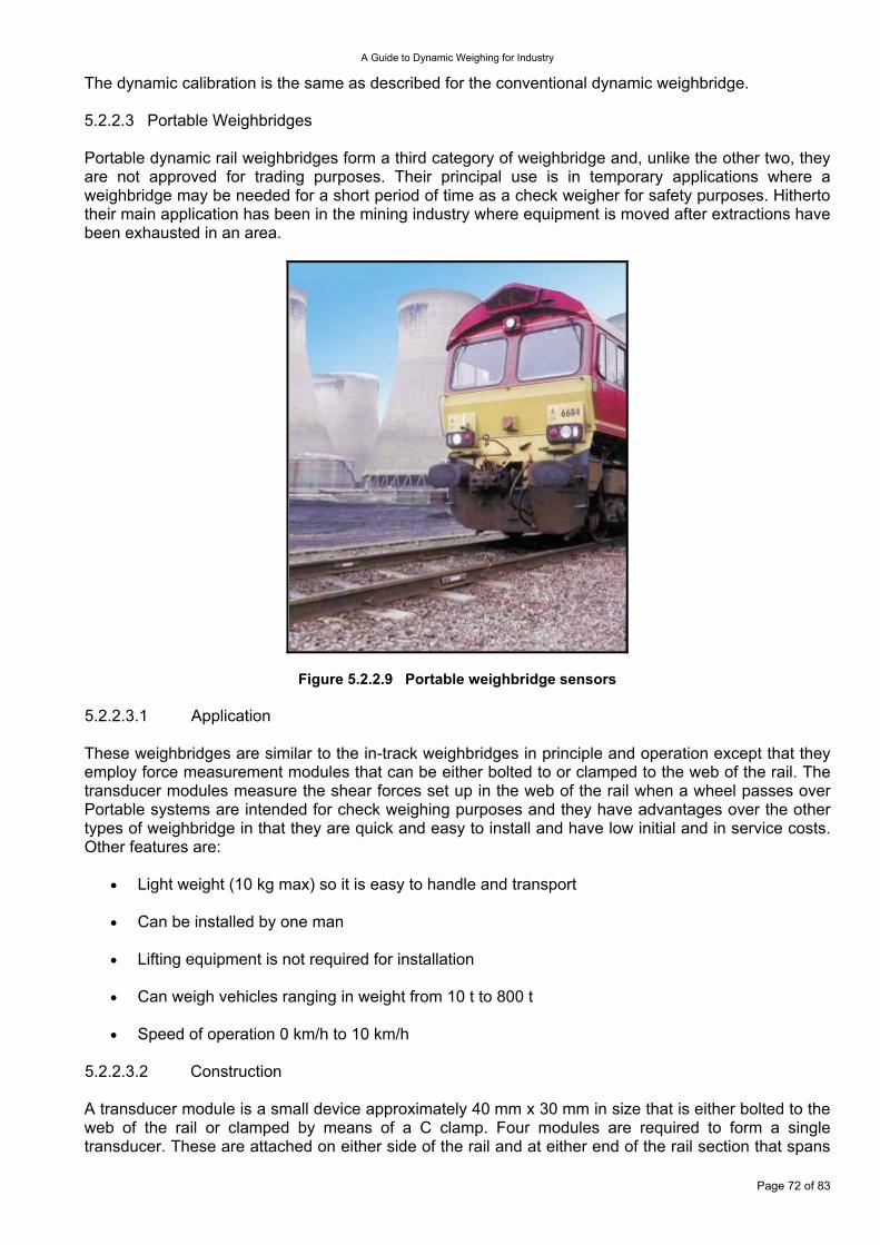
A Guide to Dynamic Weighing for Industry
The dynamic calibration is the same as described for the conventional dynamic weighbridge. 5.2.2.3 Portable Weighbridges Portable dynamic rail weighbridges form a third category of weighbridge and, unlike the other two, they are not approved for trading purposes. Their principal use is in temporary applications where a weighbridge may be needed for a short period of time as a check weigher for safety purposes. Hitherto their main application has been in the mining industry where equipment is moved after extractions have been exhausted in an area.
Figure 5.2.2.9 Portable weighbridge sensors 5.2.2.3.1 Application These weighbridges are similar to the in-track weighbridges in principle and operation except that they employ force measurement modules that can be either bolted to or clamped to the web of the rail. The transducer modules measure the shear forces set up in the web of the rail when a wheel passes over Portable systems are intended for check weighing purposes and they have advantages over the other types of weighbridge in that they are quick and easy to install and have low initial and in service costs. Other features are:
Light weight (10 kg max) so it is easy to handle and transport •
•
•
•
•
Can be installed by one man
Lifting equipment is not required for installation
Can weigh vehicles ranging in weight from 10 t to 800 t
Speed of operation 0 km/h to 10 km/h
5.2.2.3.2 Construction A transducer module is a small device approximately 40 mm x 30 mm in size that is either bolted to the web of the rail or clamped by means of a C clamp. Four modules are required to form a single transducer. These are attached on either side of the rail and at either end of the rail section that spans
Page 72 of 83
A Guide to Dynamic Weighing for Industry
two adjacent sleepers. After the modules have been attached they are protected from damage by means of a protective cover. The transducers interface to a weight controller that provides basic functionality. 5.2.2.3.3 Typical Performance This type of weighing system is not approved for transaction weighing. Its primary role is check weighing for overloading of wagons. Typical accuracy is ±2 % per wagon and ±1 % of the total train weight when weighing short trains at speeds of up to 5 km/h. 5.2.2.3.4 Factors Affecting Accuracy The accuracy of this type of weighbridge crucially depends upon the interface between the transducer modules and the rail web and it is necessary therefore to select a flat section that is free of rust and pitting. The dynamic weighing factors that affect accuracy of the other weighbridge types also affect this weighbridge. 5.2.2.3.5 Calibration/Verification This weighbridge system is calibrated in the same manner as the in-track system. 5.2.3 Catch Weighing Catch Weighing Machines are mainly used for trade purposes and as such are regulated in the European Community by the MID. Confirmity can be established through the application of a Normative Document based OIML recommendation R 51. The MID divides catch weighing machines into two categories:
Machines that weigh individual packages or items and then use the weight measurement to place the weighed objects into sets, dependant on their individual weights and the characteristics of the average weight of a given batch of similar objects. The recommendation designates these as ‘Category X’ machines. They are also commonly known as Check Weighing Machines. These machines are also used in a similar way for non-regulated quality control purposes.
•
•
Machines that weigh individual packages or items and then use the measurement to describe the individual item in terms of its weight and possibly price. Such machines also incorporate labelling devices to attach a descriptive printed label to the object. The recommendation designates these as ‘Category Y’ machines.
Page 73 of 83
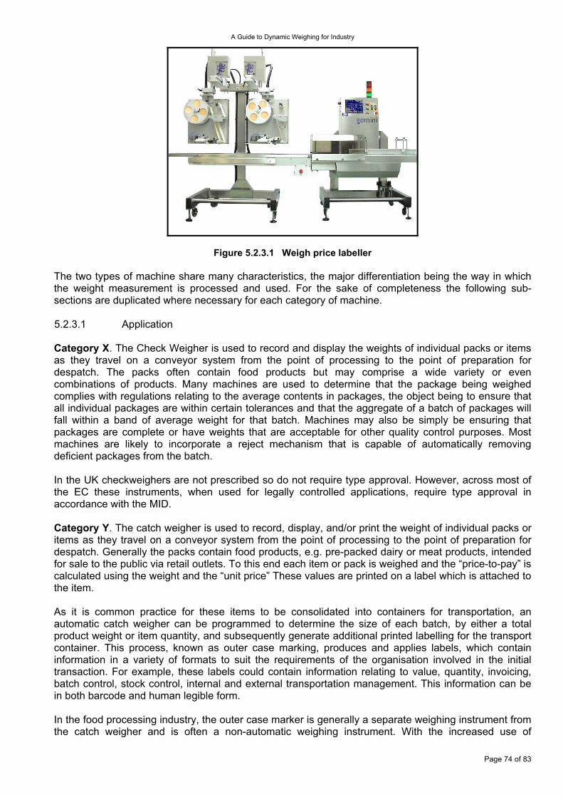
A Guide to Dynamic Weighing for Industry
Figure 5.2.3.1 Weigh price labeller The two types of machine share many characteristics, the major differentiation being the way in which the weight measurement is processed and used. For the sake of completeness the following sub-sections are duplicated where necessary for each category of machine. 5.2.3.1 Application Category X. The Check Weigher is used to record and display the weights of individual packs or items as they travel on a conveyor system from the point of processing to the point of preparation for despatch. The packs often contain food products but may comprise a wide variety or even combinations of products. Many machines are used to determine that the package being weighed complies with regulations relating to the average contents in packages, the object being to ensure that all individual packages are within certain tolerances and that the aggregate of a batch of packages will fall within a band of average weight for that batch. Machines may also be simply be ensuring that packages are complete or have weights that are acceptable for other quality control purposes. Most machines are likely to incorporate a reject mechanism that is capable of automatically removing deficient packages from the batch. In the UK checkweighers are not prescribed so do not require type approval. However, across most of the EC these instruments, when used for legally controlled applications, require type approval in accordance with the MID. Category Y. The catch weigher is used to record, display, and/or print the weight of individual packs or items as they travel on a conveyor system from the point of processing to the point of preparation for despatch. Generally the packs contain food products, e.g. pre-packed dairy or meat products, intended for sale to the public via retail outlets. To this end each item or pack is weighed and the “price-to-pay” is calculated using the weight and the “unit price” These values are printed on a label which is attached to the item. As it is common practice for these items to be consolidated into containers for transportation, an automatic catch weigher can be programmed to determine the size of each batch, by either a total product weight or item quantity, and subsequently generate additional printed labelling for the transport container. This process, known as outer case marking, produces and applies labels, which contain information in a variety of formats to suit the requirements of the organisation involved in the initial transaction. For example, these labels could contain information relating to value, quantity, invoicing, batch control, stock control, internal and external transportation management. This information can be in both barcode and human legible form. In the food processing industry, the outer case marker is generally a separate weighing instrument from the catch weigher and is often a non-automatic weighing instrument. With the increased use of
Page 74 of 83
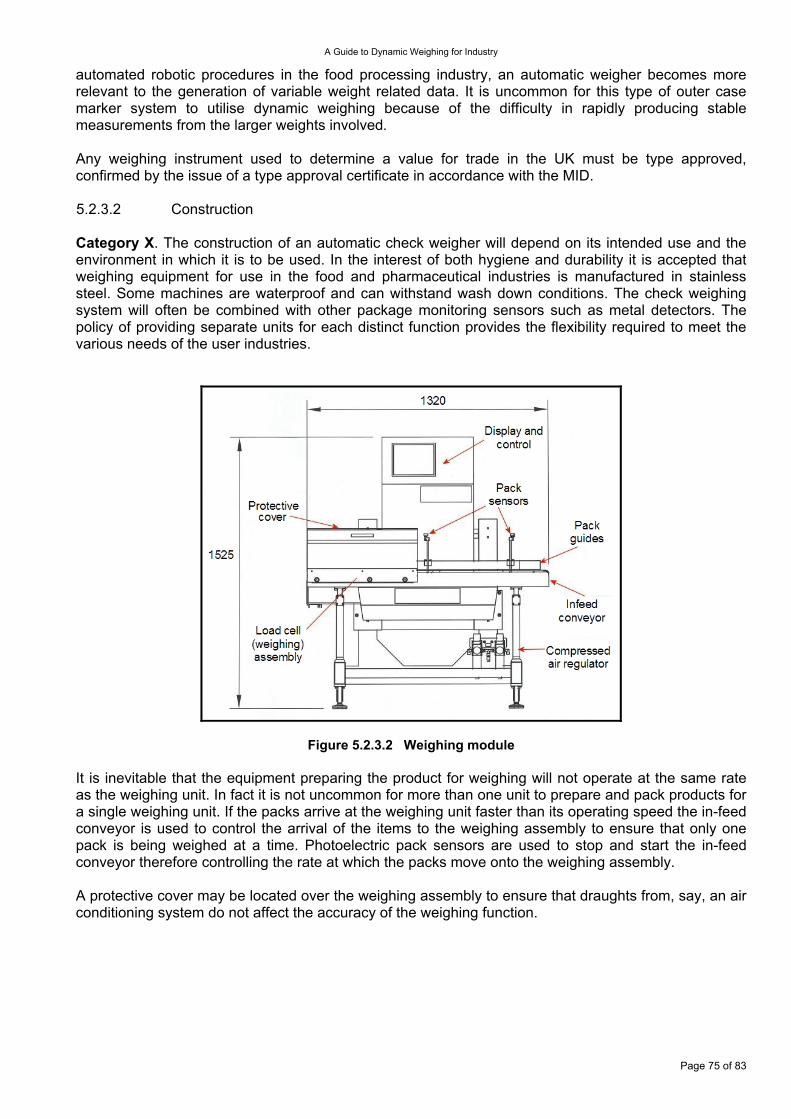
A Guide to Dynamic Weighing for Industry
automated robotic procedures in the food processing industry, an automatic weigher becomes more relevant to the generation of variable weight related data. It is uncommon for this type of outer case marker system to utilise dynamic weighing because of the difficulty in rapidly producing stable measurements from the larger weights involved. Any weighing instrument used to determine a value for trade in the UK must be type approved, confirmed by the issue of a type approval certificate in accordance with the MID. 5.2.3.2 Construction Category X. The construction of an automatic check weigher will depend on its intended use and the environment in which it is to be used. In the interest of both hygiene and durability it is accepted that weighing equipment for use in the food and pharmaceutical industries is manufactured in stainless steel. Some machines are waterproof and can withstand wash down conditions. The check weighing system will often be combined with other package monitoring sensors such as metal detectors. The policy of providing separate units for each distinct function provides the flexibility required to meet the various needs of the user industries.
Figure 5.2.3.2 Weighing module It is inevitable that the equipment preparing the product for weighing will not operate at the same rate as the weighing unit. In fact it is not uncommon for more than one unit to prepare and pack products for a single weighing unit. If the packs arrive at the weighing unit faster than its operating speed the in-feed conveyor is used to control the arrival of the items to the weighing assembly to ensure that only one pack is being weighed at a time. Photoelectric pack sensors are used to stop and start the in-feed conveyor therefore controlling the rate at which the packs move onto the weighing assembly. A protective cover may be located over the weighing assembly to ensure that draughts from, say, an air conditioning system do not affect the accuracy of the weighing function.
Page 75 of 83
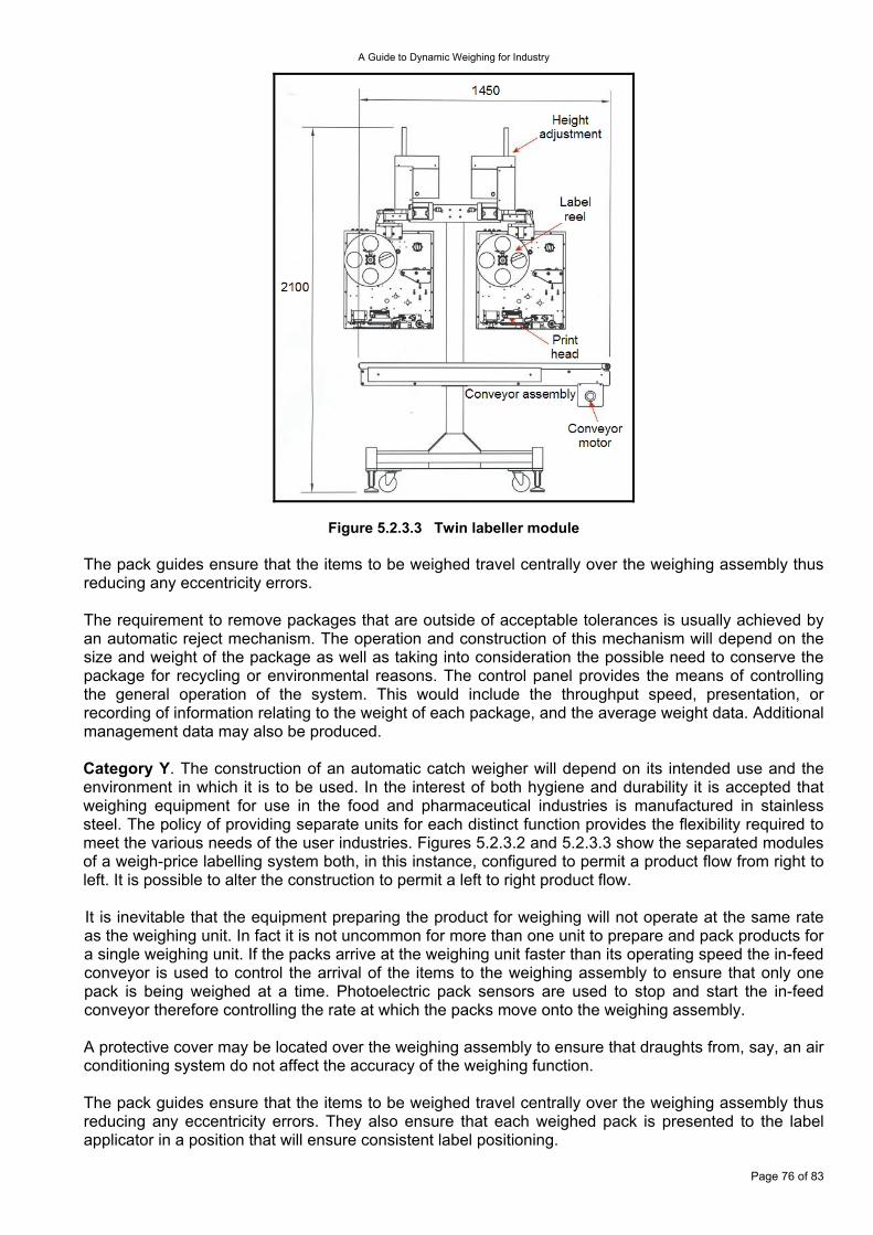
A Guide to Dynamic Weighing for Industry
Figure 5.2.3.3 Twin labeller module The pack guides ensure that the items to be weighed travel centrally over the weighing assembly thus reducing any eccentricity errors. The requirement to remove packages that are outside of acceptable tolerances is usually achieved by an automatic reject mechanism. The operation and construction of this mechanism will depend on the size and weight of the package as well as taking into consideration the possible need to conserve the package for recycling or environmental reasons. The control panel provides the means of controlling the general operation of the system. This would include the throughput speed, presentation, or recording of information relating to the weight of each package, and the average weight data. Additional management data may also be produced. Category Y. The construction of an automatic catch weigher will depend on its intended use and the environment in which it is to be used. In the interest of both hygiene and durability it is accepted that weighing equipment for use in the food and pharmaceutical industries is manufactured in stainless steel. The policy of providing separate units for each distinct function provides the flexibility required to meet the various needs of the user industries. Figures 5.2.3.2 and 5.2.3.3 show the separated modules of a weigh-price labelling system both, in this instance, configured to permit a product flow from right to left. It is possible to alter the construction to permit a left to right product flow. It is inevitable that the equipment preparing the product for weighing will not operate at the same rate as the weighing unit. In fact it is not uncommon for more than one unit to prepare and pack products for a single weighing unit. If the packs arrive at the weighing unit faster than its operating speed the in-feed conveyor is used to control the arrival of the items to the weighing assembly to ensure that only one pack is being weighed at a time. Photoelectric pack sensors are used to stop and start the in-feed conveyor therefore controlling the rate at which the packs move onto the weighing assembly. A protective cover may be located over the weighing assembly to ensure that draughts from, say, an air conditioning system do not affect the accuracy of the weighing function. The pack guides ensure that the items to be weighed travel centrally over the weighing assembly thus reducing any eccentricity errors. They also ensure that each weighed pack is presented to the label applicator in a position that will ensure consistent label positioning.
Page 76 of 83
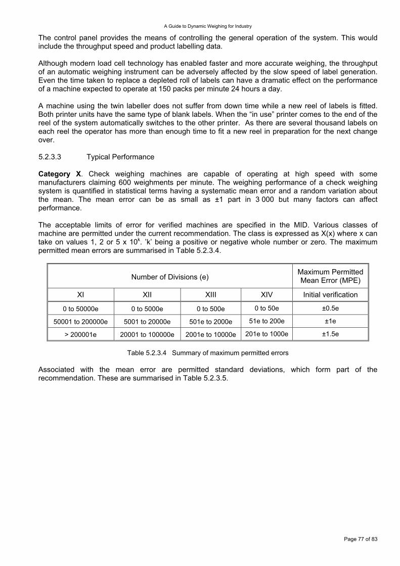
A Guide to Dynamic Weighing for Industry
The control panel provides the means of controlling the general operation of the system. This would include the throughput speed and product labelling data. Although modern load cell technology has enabled faster and more accurate weighing, the throughput of an automatic weighing instrument can be adversely affected by the slow speed of label generation. Even the time taken to replace a depleted roll of labels can have a dramatic effect on the performance of a machine expected to operate at 150 packs per minute 24 hours a day. A machine using the twin labeller does not suffer from down time while a new reel of labels is fitted. Both printer units have the same type of blank labels. When the “in use” printer comes to the end of the reel of the system automatically switches to the other printer. As there are several thousand labels on each reel the operator has more than enough time to fit a new reel in preparation for the next change over. 5.2.3.3 Typical Performance Category X. Check weighing machines are capable of operating at high speed with some manufacturers claiming 600 weighments per minute. The weighing performance of a check weighing system is quantified in statistical terms having a systematic mean error and a random variation about the mean. The mean error can be as small as ±1 part in 3 000 but many factors can affect performance. The acceptable limits of error for verified machines are specified in the MID. Various classes of machine are permitted under the current recommendation. The class is expressed as X(x) where x can take on values 1, 2 or 5 x 10k. ’k’ being a positive or negative whole number or zero. The maximum permitted mean errors are summarised in Table 5.2.3.4.
Number of Divisions (e)
Maximum Permitted Mean Error (MPE)
XI XII XIII XIV Initial verification
0 to 50000e 0 to 5000e 0 to 500e 0 to 50e ±0.5e
50001 to 200000e 5001 to 20000e 501e to 2000e 51e to 200e ±1e
> 200001e 20001 to 100000e 2001e to 10000e 201e to 1000e ±1.5e
Table 5.2.3.4 Summary of maximum permitted errors Associated with the mean error are permitted standard deviations, which form part of the recommendation. These are summarised in Table 5.2.3.5.
Page 77 of 83
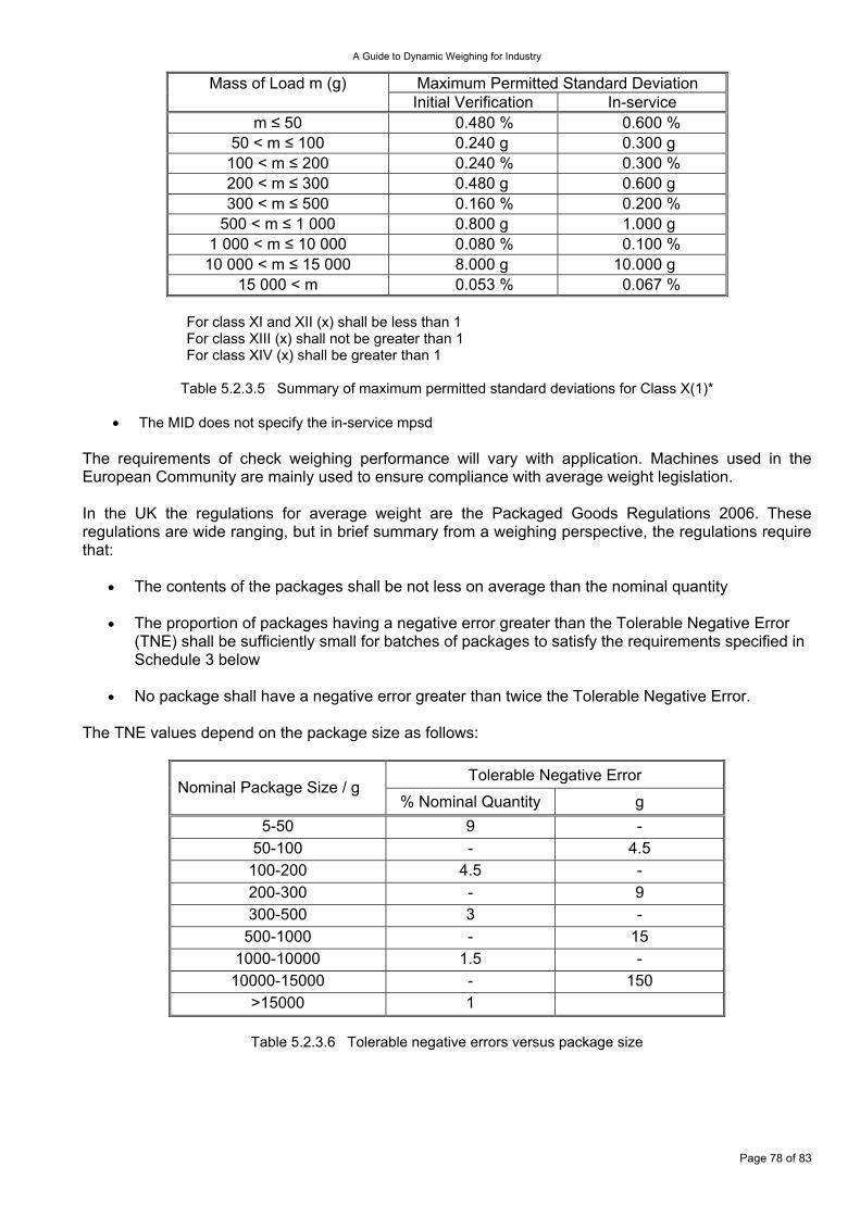
A Guide to Dynamic Weighing for Industry
Maximum Permitted Standard Deviation Mass of Load m (g) Initial Verification In-service
m ≤ 50 0.480 % 0.600 % 50 < m ≤ 100 0.240 g 0.300 g
100 < m ≤ 200 0.240 % 0.300 % 200 < m ≤ 300 0.480 g 0.600 g 300 < m ≤ 500 0.160 % 0.200 %
500 < m ≤ 1 000 0.800 g 1.000 g 1 000 < m ≤ 10 000 0.080 % 0.100 %
10 000 < m ≤ 15 000 8.000 g 10.000 g 15 000 < m 0.053 % 0.067 %
For class XI and XII (x) shall be less than 1 For class XIII (x) shall not be greater than 1 For class XIV (x) shall be greater than 1
Table 5.2.3.5 Summary of maximum permitted standard deviations for Class X(1)*
The MID does not specify the in-service mpsd •
•
•
•
The requirements of check weighing performance will vary with application. Machines used in the European Community are mainly used to ensure compliance with average weight legislation. In the UK the regulations for average weight are the Packaged Goods Regulations 2006. These regulations are wide ranging, but in brief summary from a weighing perspective, the regulations require that:
The contents of the packages shall be not less on average than the nominal quantity
The proportion of packages having a negative error greater than the Tolerable Negative Error (TNE) shall be sufficiently small for batches of packages to satisfy the requirements specified in Schedule 3 below
No package shall have a negative error greater than twice the Tolerable Negative Error.
The TNE values depend on the package size as follows:
Tolerable Negative Error Nominal Package Size / g
% Nominal Quantity g 5-50 9 -
50-100 - 4.5 100-200 4.5 - 200-300 - 9 300-500 3 -
500-1000 - 15 1000-10000 1.5 -
10000-15000 - 150 >15000 1
Table 5.2.3.6 Tolerable negative errors versus package size
Page 78 of 83

A Guide to Dynamic Weighing for Industry
Schedule 3 states:
The “minimum acceptable contents” are calculated by subtracting the TNE from the nominal quantity
•
•
•
Packages in the batch whose content is less than the minimum acceptable content are considered to be defective
The acceptable number of defective packages per batch depends upon the batch size and the sampling plan used
One of three sampling plans is permitted:
Single Sample – Non-destructive Number of Defective Packages
Number in Batch Number in Sample Acceptance Criterion Rejection Criterion 100 to 500 50 3 4
501 to 3 200 80 5 6 > 3 201 125 7 8
Double Sample – Non-destructive
Number of Defective Packages Number in Batch Number in
Sample Aggregate Sample
Number Acceptance
Criterion Rejection Criterion
1st - 30 30 1 3 100 to 500 2nd - 30 60 4 5
1st - 50 50 2 5 501 to 3 200 2nd - 50 100 6 7
1st - 80 80 3 7 >3 201 2nd - 80 160 8 9
Single Sample – Destructive
Number of Defective Packages Number in Batch Number in Sample Acceptance Criterion Rejection Criterion
Whatever the number ≥100 20 1 2
Table 5.2.3.7 Details of the permitted sample plans
The equipment used to perform the measurements is required in the regulations to be ‘Suitable for the use to which it is put’. In the UK the DTI issues guidelines on this subject (Ref. URN 06/1087). This guideline effectively precludes the use of non-verified weighing systems to perform the above checks. The measurement uncertainty should be taken into account when determining the overall function of checking a weight. Consider a machine that is being used to determine that an object with a nominal weight of 250 g has a specified minimum weight of 240 g. Should the machine have a measurement uncertainty of ±1 g then the reject mechanism will need to reject any object indicated to weigh less than 241 g plus an allowance for the random error to effectively ensure none is defective. Category Y. The performance of a verified catch weighing machine must satisfy the requirements of the MID in the European Union. When used dynamically the maximum permitted errors are shown in Table 5.2.3.4. The sub classes; Y(I), Y(II), Y(a) and Y(b), for particular applications are determined by national requirements.
Page 79 of 83
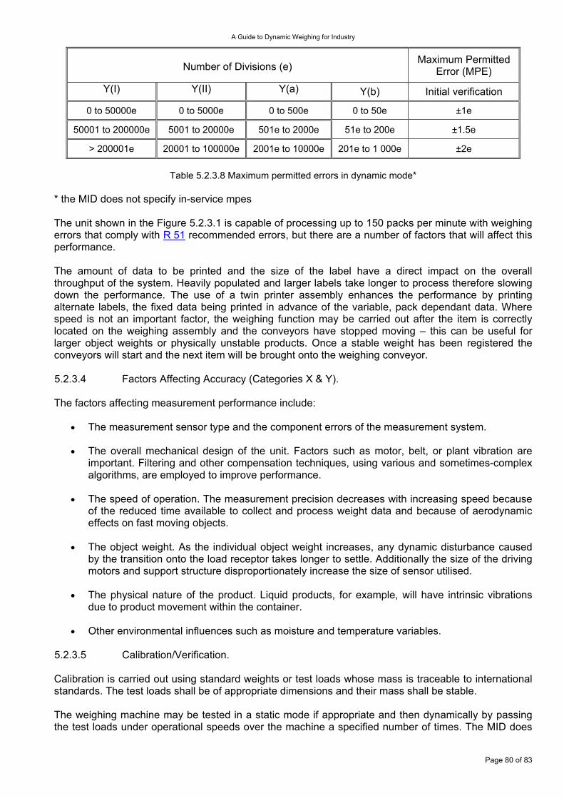
A Guide to Dynamic Weighing for Industry
Number of Divisions (e)
Maximum Permitted Error (MPE)
Y(I) Y(II) Y(a) Y(b) Initial verification
0 to 50000e 0 to 5000e 0 to 500e 0 to 50e ±1e
50001 to 200000e 5001 to 20000e 501e to 2000e 51e to 200e ±1.5e
> 200001e 20001 to 100000e 2001e to 10000e 201e to 1 000e ±2e
Table 5.2.3.8 Maximum permitted errors in dynamic mode* * the MID does not specify in-service mpes The unit shown in the Figure 5.2.3.1 is capable of processing up to 150 packs per minute with weighing errors that comply with R 51 recommended errors, but there are a number of factors that will affect this performance. The amount of data to be printed and the size of the label have a direct impact on the overall throughput of the system. Heavily populated and larger labels take longer to process therefore slowing down the performance. The use of a twin printer assembly enhances the performance by printing alternate labels, the fixed data being printed in advance of the variable, pack dependant data. Where speed is not an important factor, the weighing function may be carried out after the item is correctly located on the weighing assembly and the conveyors have stopped moving – this can be useful for larger object weights or physically unstable products. Once a stable weight has been registered the conveyors will start and the next item will be brought onto the weighing conveyor. 5.2.3.4 Factors Affecting Accuracy (Categories X & Y). The factors affecting measurement performance include:
The measurement sensor type and the component errors of the measurement system. •
•
•
•
•
•
The overall mechanical design of the unit. Factors such as motor, belt, or plant vibration are important. Filtering and other compensation techniques, using various and sometimes-complex algorithms, are employed to improve performance.
The speed of operation. The measurement precision decreases with increasing speed because of the reduced time available to collect and process weight data and because of aerodynamic effects on fast moving objects.
The object weight. As the individual object weight increases, any dynamic disturbance caused by the transition onto the load receptor takes longer to settle. Additionally the size of the driving motors and support structure disproportionately increase the size of sensor utilised.
The physical nature of the product. Liquid products, for example, will have intrinsic vibrations due to product movement within the container.
Other environmental influences such as moisture and temperature variables.
5.2.3.5 Calibration/Verification. Calibration is carried out using standard weights or test loads whose mass is traceable to international standards. The test loads shall be of appropriate dimensions and their mass shall be stable. The weighing machine may be tested in a static mode if appropriate and then dynamically by passing the test loads under operational speeds over the machine a specified number of times. The MID does
Page 80 of 83
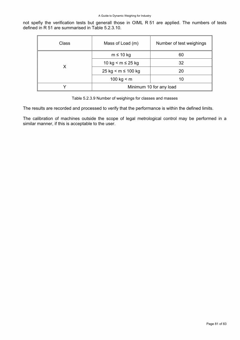
A Guide to Dynamic Weighing for Industry
not spefiy the verification tests but generall those in OIML R 51 are applied. The numbers of tests defined in R 51 are summarised in Table 5.2.3.10.
Class Mass of Load (m) Number of test weighings
m ≤ 10 kg 60
10 kg < m ≤ 25 kg 32
25 kg < m ≤ 100 kg 20 X
100 kg < m 10
Y Minimum 10 for any load
Table 5.2.3.9 Number of weighings for classes and masses The results are recorded and processed to verify that the performance is within the defined limits. The calibration of machines outside the scope of legal metrological control may be performed in a similar manner, if this is acceptable to the user.
Page 81 of 83
A Guide to Dynamic Weighing for Industry
6. BIBLIOGRAPHY 6.1 Useful Reading Material. 1 A Code of Practice for the Calibration of Industrial Process Weighing Systems, InstMC WGC0496,
1996 2 A Guide to the Specification and Procurement of Industrial Process Weighing Systems,
InstMC WGC1099, 2000 3 Evaluation of measurement data - Guide to the expression of uncertainty in measurement,
JCGM 100:2008 (GUM 1995 with minor corrections) 4 Consolidated Code of Practice, Enforcement Weighing of Vehicles, Vehicle & Operator Services
Agency, 2009 5 A Simplified Guide to Lorry Types and Weights, Department for Transport, 2003 6 Colijn H., Weighing and Proportioning of Bulk Solids, Trans Tech Publications, 1983 7 Norden K.E., Electronic Weighing - Fundamentals and Applications, Butterworth-Heinemann Ltd,
1993 8 Norden K.E., Electronic Weighing in Industrial Processes, Granada Publishing Ltd, 1984 6.2 Recommendations by the International Organisation of Legal Metrology (OIML) and Legislative Documents R 50-1 1997 Continuous totalizing automatic weighing instruments (belt weighers).
Part 1 : Metrological and technical requirements - Tests R 50-2 1997 Continuous totalizing automatic weighing instruments (belt weighers).
Part 2 : Test report format R 51-1 2006
Automatic catchweighing instruments. Part 1 : Metrological and technical requirements - Tests
R 51-2 2006 Automatic catchweighing instruments. Part 2 : Test report format
R 61-1 2004 Automatic gravimetric filling instruments. Part 1 : Metrological and technical requirements - Tests
R 61-2 2004 Automatic gravimetric filling instruments. Part 2: Test report format
R 76-1 2006 Non-automatic weighing instruments. Part 1 : Metrological and technical requirements - Tests
R 76-2 2007 Non-automatic weighing instruments. Part 2 : Test report format
R 87 2004 Quantity of product in prepackages R 87 Erratum 2008 Erratum (2008.06.16) to R 87 (Edition 2004) Quantity of product in
prepackages R 106-1 1997 Automatic rail-weighbridges.
Part 1 : Metrological and technical requirements - Tests R 106-2 1997 Automatic rail-weighbridges.
Part 2 : Test report format R 107-1 2007 Discontinuous totalizing automatic weighing instruments (totalizing hopper
weighers). Part 1 : Metrological and technical requirements - Tests R 107-2 2007 Discontinuous totalizing automatic weighing instruments (totalizing hopper
weighers). Part 2 : Test report format R 134-1 2006 Automatic instruments for weighing road vehicles in motion and measuring
axle loads. Part 1: Metrological and technical requirements – Tests R 134-2 2009 Automatic instruments for weighing road vehicles in motion and measuring
axle loads. Part 2: Test report format
Directive 2004/22/EC Measuring Instruments Directive (MID)
URN 06/1087 The Weights and Measures (Packaged Goods Regulations) 2006 – Guidance Note Issued by DTI
Page 82 of 83

A Guide to Dynamic Weighing for Industry
Page 83 of 83
7. USEFUL ADDRESSES There are a number of Weighing & Force Measurement Panel publications where a number of useful addresses are given. The reader is directed to consult the following website and the publications listed there: http://www.npl.co.uk/instmc-wfmp


