A Guide to Retrofitting Homes for Wind Protection Course No: S08-004 Credit: 8 PDH Allen Hughes, P.E. Continuing Education and Development, Inc. 9 Greyridge Farm Court Stony Point, NY 10980 P: (877) 322-5800 F: (877) 322-4774 [email protected]
Transcript
A Guide to Retrofitting Homes for Wind Protection Course No: S08-004
Credit: 8 PDH
Allen Hughes, P.E.
Continuing Education and Development, Inc. 9 Greyridge Farm Court Stony Point, NY 10980 P: (877) 322-5800 F: (877) 322-4774 [email protected]
Wind Retrofit Guide for Residential Buildings FEMA P-804 / December 2010
Any opinions, findings, conclusions, or recommendations expressed in this publication do not necessarily reflect the views of FEMA. Additionally, neither FEMA nor any of its employees makes any warranty, expressed or implied, or assumes any legal liability or responsibility for the accuracy, completeness, or usefulness of any information, product, or process included in this publication. Users of information contained in this publication assume all liability arising from such use.
Acknowledgements Authors
Omar Kapur, URS Corporation Amit Mahadevia, URS Corporation Jae Park, URS Corporation Samantha Passman, URS Corporation Manny Perotin, PBS&J Adam Reeder, PBS&J Laura Seitz, URS Corporation Adrienne Sheldon, URS Corporation Scott Tezak, URS Corporation
FEMA Reviewers and Contributors
Katy Brown, FEMA Region IV Brooke Buchanan, FEMA Region VIII Franki Coons, FEMA HQ Robin Danforth, FEMA Region III John Ingargiola, FEMA HQ Stephen Juszczyk, FEMA Mississippi Recovery Office Dennis Kizziah, FEMA Mississippi Recovery Office Ed Laatsch, FEMA HQ John LaBrune, FEMA Mississippi Recovery Office John Plisich, FEMA Region IV Shabbar Saifee, FEMA HQ Ed Smith, FEMA HQ Jody Springer, FEMA HQ Paul Tertell, FEMA HQ Joyce Wells, FEMA Region IV Charles Williams, FEMA Region IV Brian Willsey, FEMA HQ
Reviewers and Contributors
Miles Anderson, Florida Division of Emergency Management Brett Bowen, URS Corporation Bill Coulbourne, Applied Technology Council Frank Lavelle, Applied Research Associates Philip Line, URS Corporation Dave Low, DK Low and Associates Lee-Ann Lyons, URS Corporation Fred Malik, Institute for Business and Home Safety Shane Parson, URS Corporation Susan Patton, URS Corporation Tim Reinhold, Institute for Business and Home Safety Tom Reynolds, URS Corporation Mike Rimoldi, Federal Alliance for Safe Homes Billy Ruppert, URS Corporation Randy Schackleford, Simpson Strong-Tie Amy Siegel, URS Corporation Tom Smith, TLSmith Consulting Jeff Suhr, URS Corporation Scott Sundberg, Category X Coastal Consulting William H. York, Institute for Business and Home Safety Michael Young, RMS
This publication was funded under a HMTAP for Hazard Mitigation Support in Mississippi following Hurricane Katrina,
FEMA-DR-1604-MS, under HSFEHQ-06-D-0162 (Prime), as Task Order #HSFEHQ-09-J-0012 (Task Order 12).
Table of Contents
CHAPTER 1: Introduction ....................................................................................................................1-1 1.1 Need for Technical Guidance............................................................................................... 1-2 1.2 Wind Retrofit Project Type ................................................................................................... 1-2 1.3 Using This Guide................................................................................................................... 1-3
CHAPTER 2: Identifying the Risks and Desired Level of Protection.................................................2-1 2.1 Wind Hazards in the Hurricane-Prone Region ...................................................................2-1 2.2 Levels of Protection............................................................................................................... 2-3
2.2.1 Wind Hazards and Building Codes.......................................................................... 2-4 2.2.2 Recommended Protection and Best Practices......................................................... 2-5
CHAPTER 3: Evaluating Existing Homes ........................................................................................... 3-1 3.1 Evaluating a Home ................................................................................................................ 3-1
3.2 Determining Whether a Home Is a Good Candidate for a Wind Retrofit Project ........... 3-5 3.3 Deciding What Level of Protection to Achieve ................................................................... 3-7
5.1.1 Federal Emergency Management Agency ................................................................ 5-1 5.1.2 State Programs...........................................................................................................5-6 5.1.3 Federal Alliance for Safe Homes Program ..............................................................5-6 5.1.4 FORTIFIED for Existing Homes™ Program................................................................ 5-7
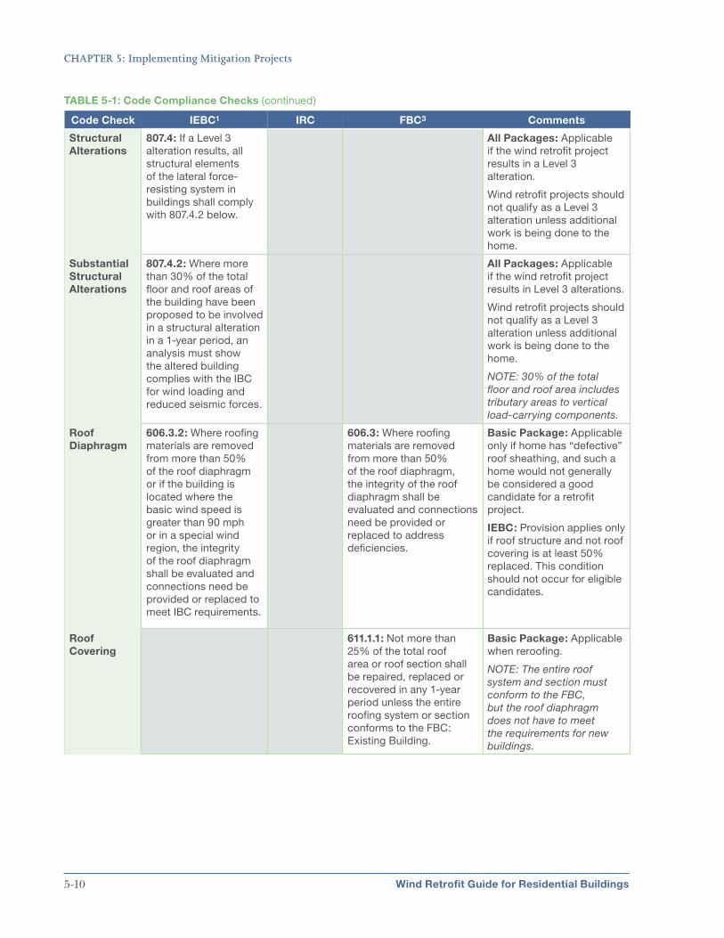
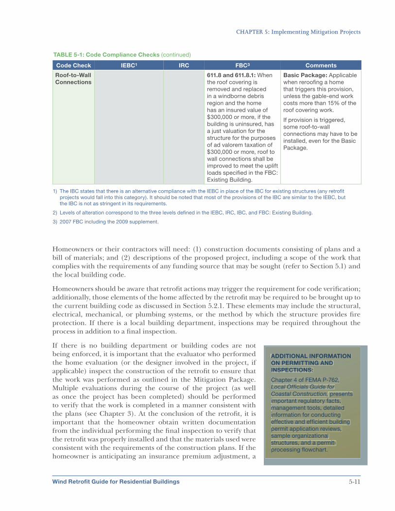
5.2 Factors to Consider When Implementing Wind Retrofit Projects ..................................... 5-7 5.2.1 Code Compliance Check .......................................................................................... 5-7 5.2.2 Permitting and Inspections ...................................................................................... 5-8 5.2.3 Construction Challenges ........................................................................................ 5-12
5.3 Addressing Other Hazards ................................................................................................. 5-13
APPENDIX A: FORTIFIED for Existing Homes™ ..................................................................................A-1
APPENDIX C: Using the Hurricane Wind Module for Determining Cost Effectiveness of Retrofit Projects ......................................................................................................C-1
APPENDIX D: References, Resources, and Links .............................................................................. D-1
APPENDIX E: Acronyms and Abbreviations.......................................................................................E-1
List of Figures
Figure 1-1: HMA grant process.......................................................................................................... 1-3
Figure 2-1: Illustration of the hurricane-prone region of the United States.................................. 2-2
Figure 2-2: Roof structure failure on a house (Galveston, TX, 2008) ............................................ 2-3
Figure 2-3: Building built to the 2001 Florida Building Code (FBC) standards with no structural damage after Hurricane Charley (North Captiva Island, 2004) ................ 2-4
Figure 3-1: Example of a window product label ...............................................................................3-4
Figure 3-2: Continuous load path for wind uplift of a residential, wood-frame building ............. 3-5
Figure 4-1: Mitigation Packages for wind retrofit projects............................................................... 4-1
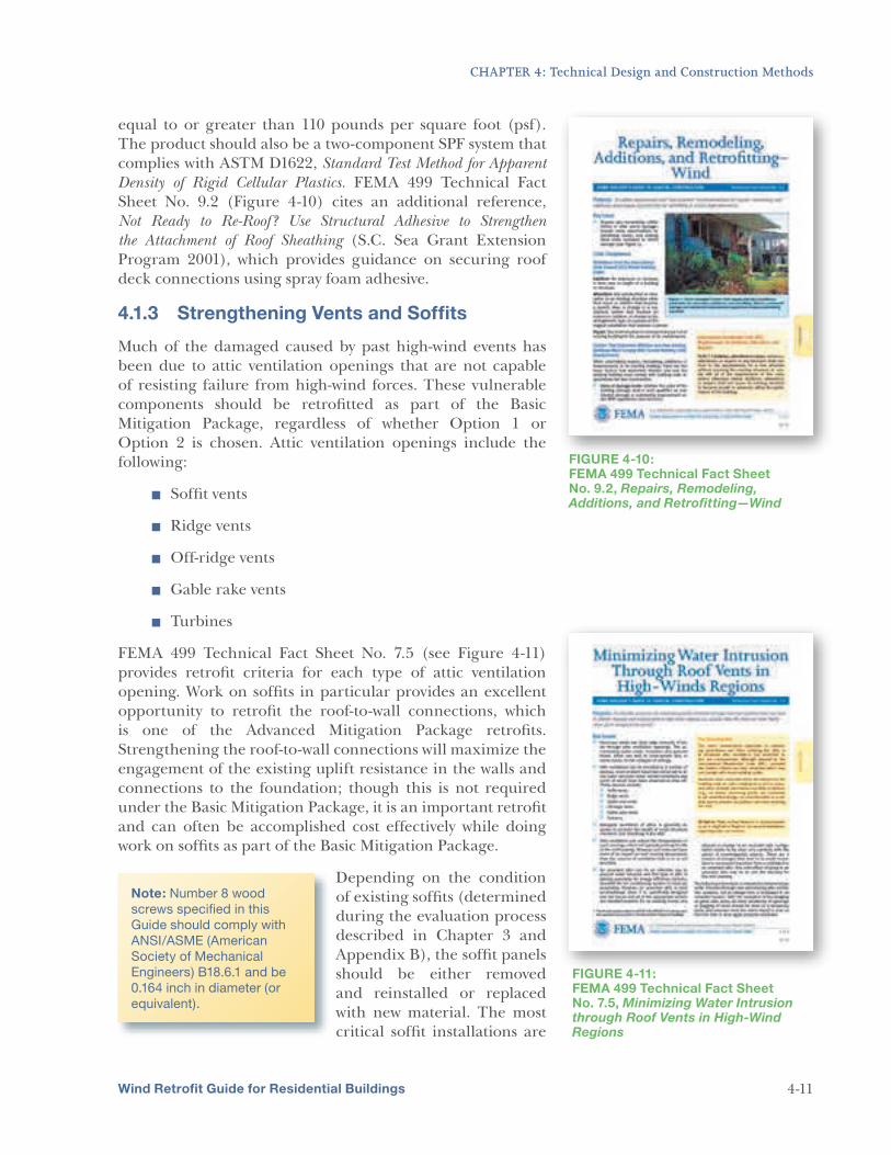
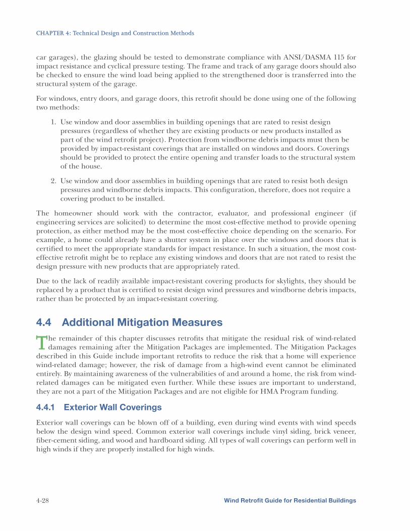
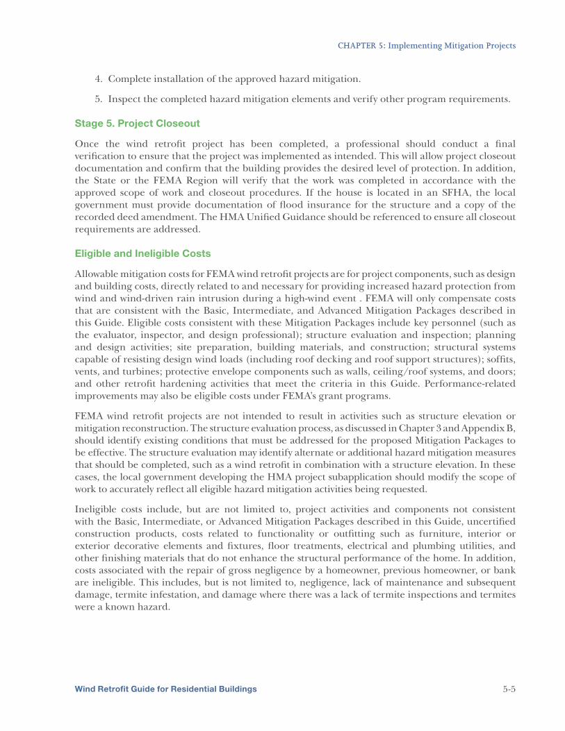
Figure 4-11: FEMA 499 Technical Fact Sheet No. 7.5, Minimizing Water Intrusion through
Roof Vents in High-Wind Regions...................................................................................... 4-11
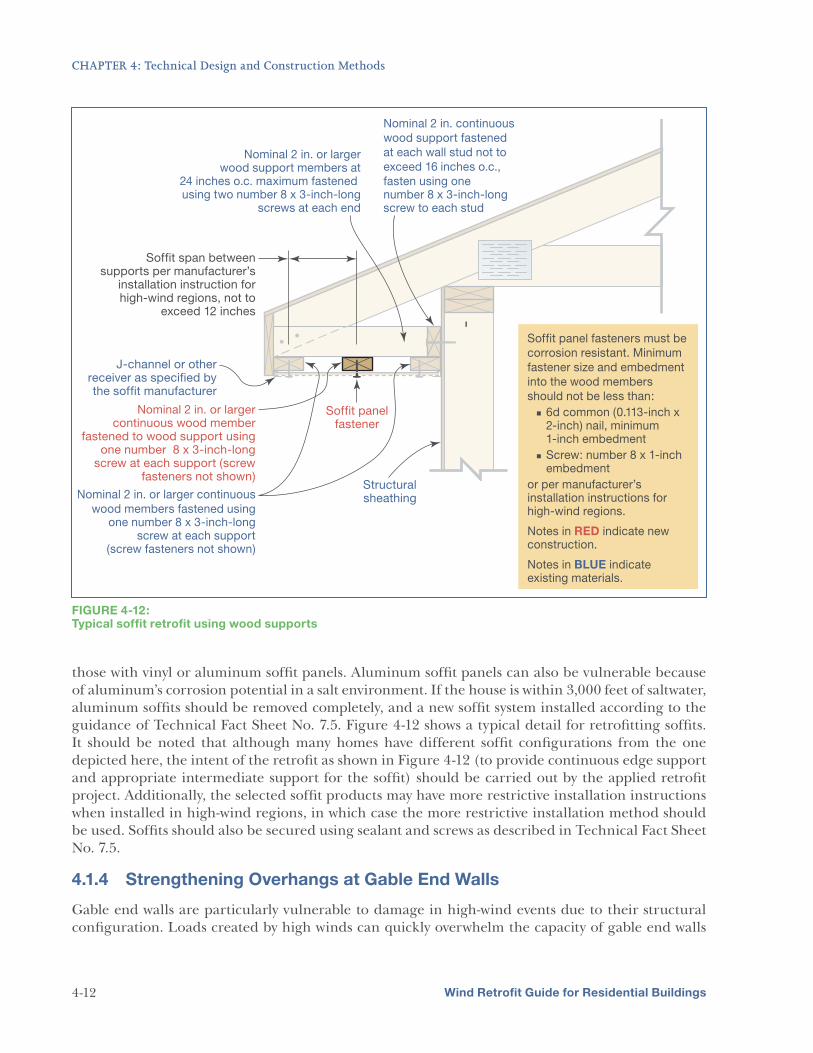
Figure 4-12: Typical soffit retrofit using wood supports................................................................... 4-12
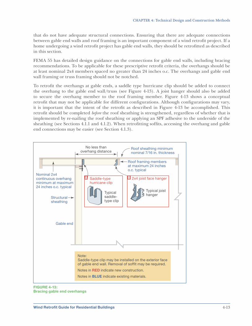
Figure 4-13: Bracing gable end overhangs ........................................................................................ 4-13
Figure 4-14: FEMA 499 Technical Fact Sheets No. 6.1, Window and Door Installation, and No. 6.2, Protection of Openings—Shutters and Glazing..................................................... 4-15
Figure 4-15: Conceptual gable end retrofit without overhangs ....................................................... 4-19
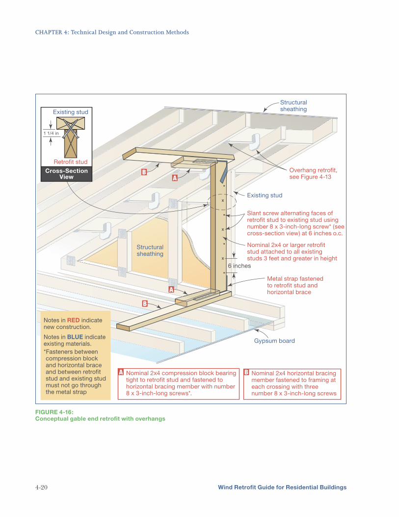
Figure 4-16: Conceptual gable end retrofit with overhangs............................................................. 4-20
Figure 4-17: Roof structure that was poorly connected to the house (Jefferson Parish, LA) ....... 4-22
Figure 4-18: FEMA 499 Technical Fact Sheets No. 4.1, Load Paths and No. 4.3, Use of
Connectors and Brackets.................................................................................................... 4-23
Figure 4-19: Load path connections of a roof system....................................................................... 4-24
Figure 4-20: Load path connections of a wall system....................................................................... 4-25
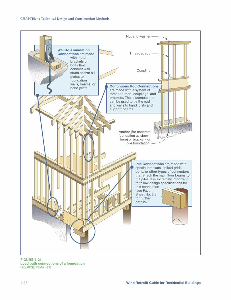
Figure 4-21: Load path connections of a foundation....................................................................... 4-26
Regions and No. 5.4, Attachment of Brick Veneer in High-Wind Regions ........................... 4-29
Figure 4-23: A home damaged by fallen trees during Hurricane Katrina (Diamondhead, MS)...................................................................................................... 4-30
Figure 5-1: HMA grants cycle process showing roles and responsibilities of each stakeholder .... 5-2
Chapter 3. Evaluating Existing Homes explains how to assess homes to determine their vulnerabilities and what type of mitigation measures would be most appropriate and feasible.
Chapter 4. Technical Design and Construction Methods provides details and specific measures for each of the three Mitigation Package categories: Basic, Intermediate, and Advanced.
Chapter 5. Implementing Mitigation Projects describes how to move a project forward, important issues and challenges that should be considered, and details about potential sources of assistance.
Appendix A. FORTIFIED for Existing Homes™ (FEH) summarizes the Institute for Business and Home Safety (IBHS) program. This program is also a “package-based” wind retrofit program for existing residential buildings that seeks to improve the performance of buildings during high-wind events.
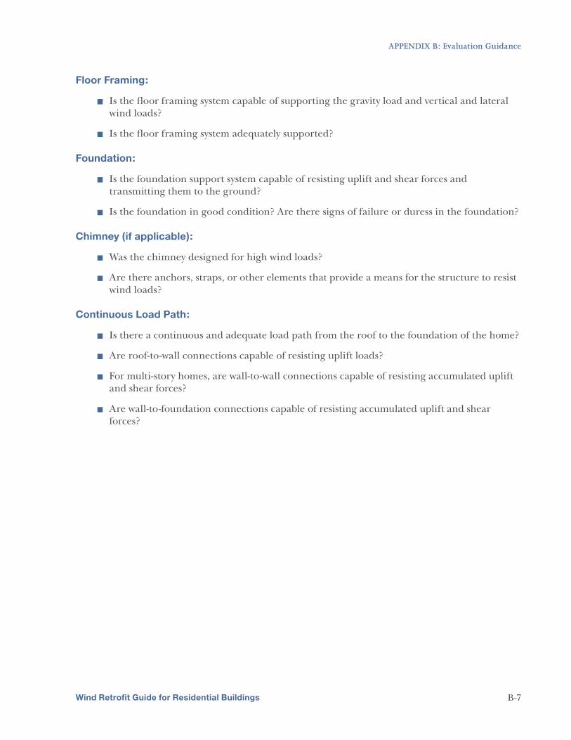
Appendix B. Evaluation Guidance provides guidance on conducting an evaluation of a home that is being considered for a wind retrofit project; this appendix supplements the information in Chapter 3.
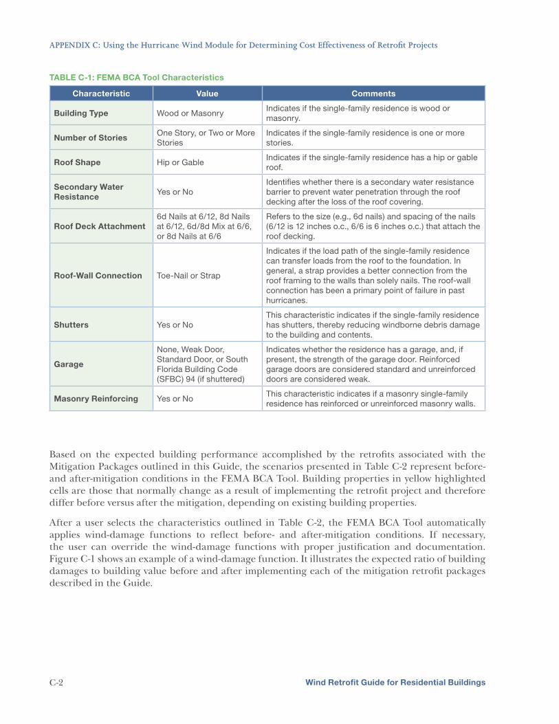
Appendix C. Using the Hurricane Wind Module for Determining Cost Effectiveness of Retrofit
Projects contains information that can be used with the FEMA BCA Tool (Version 4.5.5) to model the post-mitigation effectiveness of the projects detailed in Chapter 4. A BCA must be performed as part of a FEMA mitigation grant application.
Appendix D. Resources, References, and Links provides details on where additional resources can be located, including information about FEMA funding programs and building science publications. It also includes a list of documents, publications, and other sources used to help develop this Guide.
Appendix E. Acronyms and Abbreviations
Wind Retrofit Guide for Residential Buildings 1-4
CHAPTER 1
Introduction
Every year, homes along the coast are subject to high winds that cause extensive damage and threaten the safety and security of coastal residents. Much of this wind-related damage can be reduced or prevented by improving the performance of the buildings through retrofits
that strengthen the building’s envelope (the shell of the house, including the doors, roof covering, windows, and walls), the adequacy of the home’s load path (the connections of each part of the structure, from roof to foundation), and their ability to transfer loads without failing.
The purpose of this Guide is to provide guidance on how to improve the wind resistance of existing residential buildings in Mississippi and across the Gulf Coast. Although this Guide was developed to support initiatives in the Gulf Coast region, the content of this document should serve as guidance on retrofitting existing buildings for improved performance during high-wind events in all coastal regions; it is applicable to one- and two-family dwellings, but not to manufactured housing. Although this guidance is primarily intended to be applied in the hurricane-prone region of the United States, it may also be applied to other regions. The Federal Emergency Management Agency (FEMA) has published many other guidance documents on coastal construction as well. In areas where this Guide does not address particular material types, building layouts, and other customizable factors of homes, the Coastal Construction
Manual (FEMA 55, fourth edition to be published in 2011) should be used as a reference, as discussed in later chapters of this Guide.
There are multiple intended audiences for this Guide. Homeowners should be involved in the process of the wind retrofit project; they must understand the benefits and costs of each potential decision. Using this Guide, homeowners should work with their contractor, an evaluator, and a design professional (if necessary) to determine which package of wind retrofit activities is most appropriate for their home.
This Guide summarizes the technical
information needed for selecting and
implementing cost-effective wind
retrofit projects for residential buildings.
Implementing the Mitigation Packages in
this Guide on existing vulnerable homes
within the hurricane-prone regions of the
United States will result in their improved
performance in high-wind events.
This Guide presents mitigation measures in
packages. A package is a required set of
retrofit measures that must be implemented
for a home to provide a consistent level
of protection. This Guide identifies three
successive protection packages: Basic,
Intermediate, and Advanced.
EVALUATOR
When implementing a wind retrofit project,
homeowners or the local government will
need to work with an evaluator, who will
evaluate the existing condition of the home.
The evaluation will help determine how a
home can be retrofitted for the Mitigation
Packages outlined in this Guide.
Evaluators must possess sufficient
knowledge of the design and construction
of residential buildings to perform these
evaluations, but they need not be a
registered engineer or architect. However,
the evaluator should have knowledge of and
familiarity with the wind retrofit Mitigation
Packages and their intent as described in
this Guide.
Wind Retrofit Guide for Residential Buildings 1-1
CHAPTER 1: Introduction
State and local governments and entities who have mitigation programs in hurricane-prone regions will also benefit from this Guide by using the information to pursue, develop, and deliver technical assistance to the public on successful wind retrofit mitigation projects for residential buildings.
1.1 Need for Technical Guidance
Hurricane Katrina damaged or destroyed 234,230 single-family homes (including manufactured homes) in Mississippi alone (FEMA, 2006a). Louisiana and Mississippi did not have strong
residential building codes in their hurricane-prone regions prior to Hurricane Katrina. The impact of Hurricane Katrina has illustrated the importance of adopting and enforcing an effective building code. However, thousands of existing homes remain vulnerable to the effects of coastal high-wind events and are not designed to the same level of wind resistance required by today’s codes and standards.
In response to Hurricane Katrina, the Mississippi Emergency Management Agency’s (MEMA’s) Mitigation Section, in coordination with the Mississippi Department of Finance and Administration (DFA), has applied for a Hazard Mitigation Grant Program (HMGP) grant under presidentially declared disaster number DR-1604 (Hurricane Katrina in Mississippi) to fund wind retrofit projects for homeowners in Mississippi. This program will fund up to 75 percent of eligible costs of retrofits such as adding roof deck attachments, roof-to-wall connections, and opening protection.
Local and national FEMA staff have concluded that additional technical guidance is needed to facilitate the development of retrofit projects for residential buildings including: engineering-based prescriptive construction solutions, implementation guidance, and wind-damage function data to support user-identified damage curves for performing the related benefit-cost analysis (BCA).
1.2 Wind Retrofit Project Type
The purpose of a residential wind retrofit project is to reduce the vulnerability of and damage to homes from wind and wind-driven rain intrusion during a high-wind event such as a hurricane.
According to recent FEMA Mitigation Assessment Team (MAT) findings, there are three areas of the home that are typically vulnerable to failure due to high winds:
5
5
5
Roof and wall coverings
Openings (e.g., windows, doors)
Load path connections
Although nothing can guarantee total and absolute property and life protection from high winds, many types of wind retrofit projects can be effective and cost-beneficial in reducing damage from high-wind events.
Despite the significant damage experienced by all types of buildings during high-wind events, grant applications for wind retrofit projects have focused more on non-residential or commercial buildings and less on residential buildings. FEMA has developed this Guide to encourage wind mitigation of existing residential buildings.
The retrofits in this Guide are intended to be applied
throughout the hurricane-prone region, though they
may be applied to any home to reduce the risk to
wind-related damage. While the solutions described
in this Guide were designed primarily for wood-frame
residences, and though construction techniques can
vary considerably throughout the United States and
territories, the intent of the retrofits in this Guide may
be applied to all homes.
Wind Retrofit Guide for Residential Buildings 1-2
CHAPTER 1: Introduction
Through its Hazard Mitigation Assistance (HMA) grant programs, FEMA administers two grant programs that fund wind retrofit projects: the HMGP and the Pre-Disaster Mitigation (PDM) grant program. Hazard mitigation is defined as any sustained action taken to reduce or eliminate long-term risk to people and property from natural hazards and their effects. The HMA process cycles through five stages starting with mitigation planning and ending with successful execution of a project (Figure 1-1). Chapter 5 provides more information on the HMA process and the roles and responsibilities of different stakeholders at each stage of the process.
FIGURE 1-1: HMA grant process
1.3 Using This Guide
This Guide consists of five chapters and four appendices. Following is a brief description of each of these components. It is recommended that users review this Guide in its entirety before
pursuing the development of a wind retrofit mitigation project.
Chapter 1. Introduction provides an overview of the Guide, summarizing its purpose and contents.
Chapter 2. Identifying the Risks and Desired Level of Protection describes wind hazards, how to identify wind risks for a particular site or area, and how the wind hazard is addressed through building codes and best practices.
Wind Retrofit Guide for Residential Buildings 1-3
CHAPTER 2
Identifying the Risks and
Desired Level of Protection
To better understand the wind-related risk to a house from hurricanes, it is important to know how wind hazards are defined. Further, to understand the level of protection provided by a house before and after implementing a retrofit project, homeowners should understand or
try to identify the code to which their house was constructed and the methods and materials used during construction.
This chapter discusses wind hazards in coastal regions and summarizes how and when building codes and standards started to address these hazards. Also included is a discussion on the level of protection provided by houses, and the level of protection or performance that is reasonable to expect after implementing a wind mitigation project.
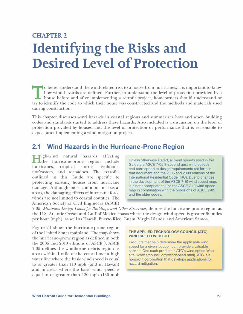
2.1 Wind Hazards in the Hurricane-Prone Region
High-wind natural hazards affecting the hurricane-prone region include
hurricanes, tropical storms, typhoons, nor’easters, and tornadoes. The retrofits outlined in this Guide are specific to protecting existing houses from hurricane damage. Although most common in coastal areas, the damaging effects of hurricane-force winds are not limited to coastal counties. The American Society of Civil Engineers (ASCE) 7-05, Minimum Design Loads for Buildings and Other Structures, defines the hurricane-prone region as the U.S. Atlantic Ocean and Gulf of Mexico coasts where the design wind speed is greater 90 miles per hour (mph), as well as Hawaii, Puerto Rico, Guam, Virgin Islands, and American Samoa.
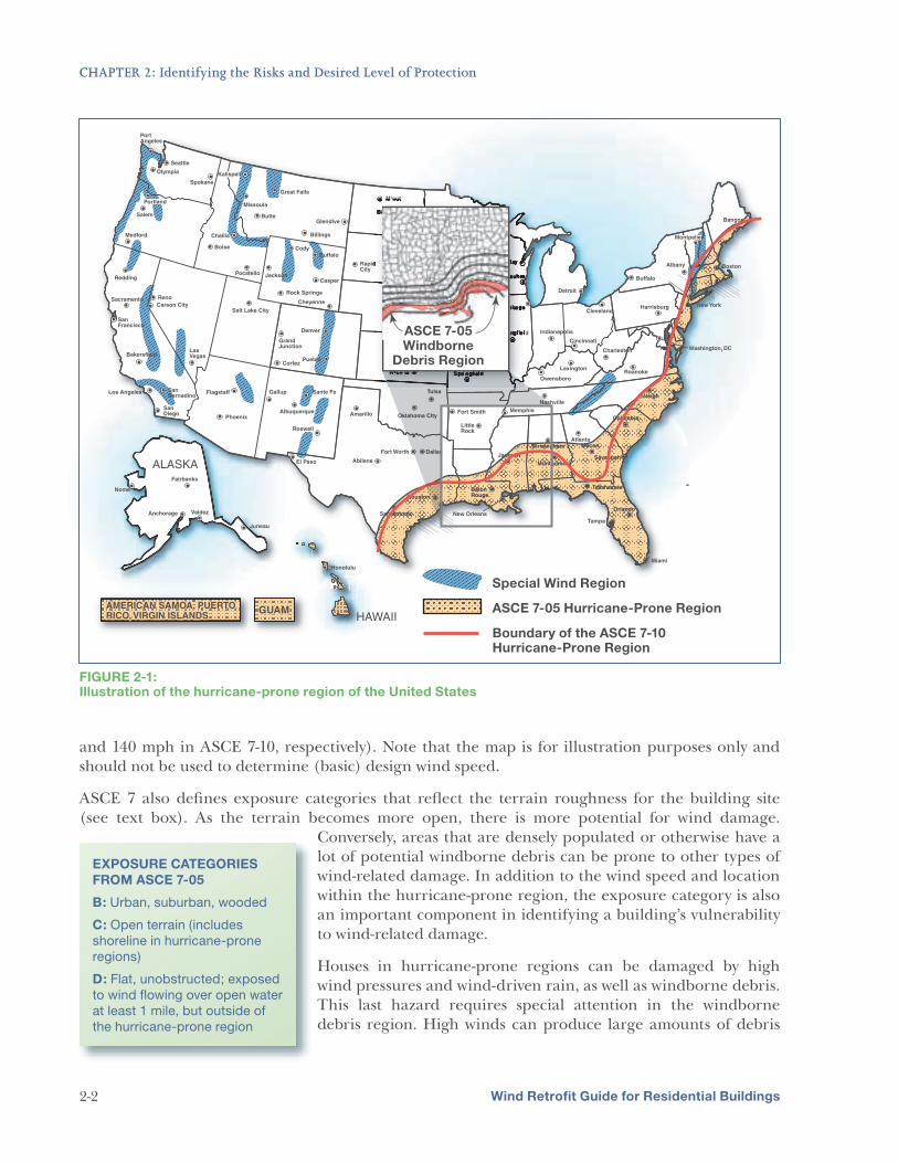
Figure 2-1 shows the hurricane-prone region of the United States mainland. The map shows the hurricane-prone region as defined in both the 2005 and 2010 editions of ASCE 7. ASCE 7-05 defines the windborne debris region as areas within 1 mile of the coastal mean high water line where the basic wind speed is equal to or greater than 110 mph (and in Hawaii) and in areas where the basic wind speed is equal to or greater than 120 mph (130 mph
Unless otherwise stated, all wind speeds used in this
Guide are ASCE 7-05 3-second gust wind speeds
and correspond to design requirements set forth in
that document and the 2006 and 2009 editions of the
International Residential Code (IRC). Due to changes
in the development of the ASCE 7-10 wind speed map,
it is not appropriate to use the ASCE 7-10 wind speed
map in combination with the provisions of ASCE 7-05
and the older codes.
THE APPLIED TECHNOLOGY COUNCIL (ATC)
WIND SPEED WEB SITE
Products that help determine the applicable wind
speed for a given location can provide a valuable
service. One such product is ATC’s wind speed Web
site (www.atcouncil.org/windspeed.html). ATC is a
nonprofit corporation that develops applications for
hazard mitigation.
Wind Retrofit Guide for Residential Buildings 2-1
CHAPTER 2: Identifying the Risks and Desired Level of Protection
FIGURE 2-1: Illustration of the hurricane-prone region of the United States
and 140 mph in ASCE 7-10, respectively). Note that the map is for illustration purposes only and should not be used to determine (basic) design wind speed.
ASCE 7 also defines exposure categories that reflect the terrain roughness for the building site (see text box). As the terrain becomes more open, there is more potential for wind damage.
Conversely, areas that are densely populated or otherwise have a lot of potential windborne debris can be prone to other types of wind-related damage. In addition to the wind speed and location within the hurricane-prone region, the exposure category is also an important component in identifying a building’s vulnerability to wind-related damage.
Houses in hurricane-prone regions can be damaged by high wind pressures and wind-driven rain, as well as windborne debris. This last hazard requires special attention in the windborne debris region. High winds can produce large amounts of debris
EXPOSURE CATEGORIES
FROM ASCE 7-05
B: Urban, suburban, wooded
C: Open terrain (includes
shoreline in hurricane-prone
regions)
D: Flat, unobstructed; exposed
to wind flowing over open water
at least 1 mile, but outside of
the hurricane-prone region
Wind Retrofit Guide for Residential Buildings 2-2
CHAPTER 2: Identifying the Risks and Desired Level of Protection
that may become windborne and perforate the building envelope and openings. Once a building is perforated, wind-driven rain can enter the building, causing water damage to the interior and contents. A broken window or glass door may also allow wind pressures to increase within the house, leading to structural damage. As such, building codes require that new homes constructed in windborne debris regions protect glazing (windows and glass doors) against damage and impacts from windborne debris. Homeowners should consider adding protection to the openings in their existing home to mitigate this risk. The inset of Figure 2-1 illustrates the windborne debris region for several Gulf Coast States. Homeowners should consult their local building department for a final determination regarding their home’s location within the windborne debris region. Homeowners should understand their potential risk based on their location to determine which retrofit package is right for their house (see Chapter 3).
2.2 Levels of Protection
Over the past few decades, building codes have progressed toward addressing design and construction practices that will result in buildings that are more resistant to high winds.
However, much of the existing building stock in hurricane-prone regions was designed and constructed to codes and standards that required far less than current codes to mitigate wind damage—or constructed to no codes at all. It is important for homeowners to be aware of the limits of the building code used to construct their house, the existing level of risk, and how and to what extent the risks can be mitigated.
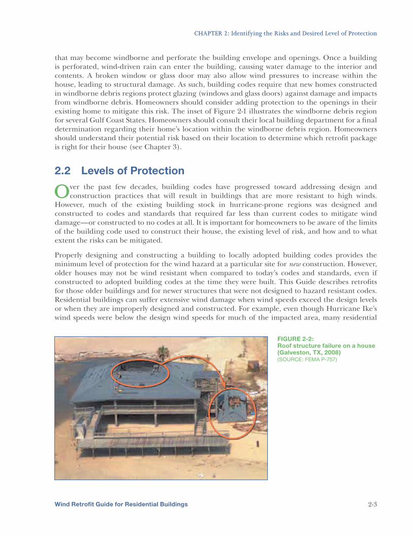
Properly designing and constructing a building to locally adopted building codes provides the minimum level of protection for the wind hazard at a particular site for new construction. However, older houses may not be wind resistant when compared to today’s codes and standards, even if constructed to adopted building codes at the time they were built. This Guide describes retrofits for those older buildings and for newer structures that were not designed to hazard resistant codes. Residential buildings can suffer extensive wind damage when wind speeds exceed the design levels or when they are improperly designed and constructed. For example, even though Hurricane Ike’s wind speeds were below the design wind speeds for much of the impacted area, many residential
FIGURE 2-2: Roof structure failure on a house (Galveston, TX, 2008) (SOURCE: FEMA P-757)
Wind Retrofit Guide for Residential Buildings 2-3
CHAPTER 2: Identifying the Risks and Desired Level of Protection
buildings suffered wind damage, some of which was disproportionate to the reported wind speeds. During Hurricane Ike, the house in Figure 2-2 sustained structural damage from wind speeds estimated at 93 mph, which was below the design wind speed.
2.2.1 Wind Hazards and Building Codes
Many States and communities now regulate the construction of buildings by adopting and enforcing building codes. Most locally adopted building codes in the United States are based on model building codes. Examples of model building codes promulgated by the International Code Council (ICC) include:
5 International Building Code (IBC) (ICC, 2009a)
5 International Residential Code for One- and Two-Family Dwellings (IRC) (ICC, 2009b)
5 International Existing Building Code (IEBC) (ICC, 2009c)
The approaches to wind design in these model codes are based on modern wind engineering provisions of ASCE 7, as well as acceptable methods for enhancing wind hazard resistance. The IRC also incorporates, by reference, industry standards in addition to ASCE 7 that are specifically recognized as accepted engineering practice for one- and two-family dwellings in high-wind regions. These standards include:
5 American Forest and Paper Association (AF&PA) Wood Frame Construction Manual for One-
and Two-Family Dwellings ([WFCM], 2001)
5 ICC Standard for Residential Construction in High-Wind Regions (ICC-600, 2008a)
5 American Iron and Steel Institute (AISI) Standard for Cold-Formed Steel Framing—Prescriptive
Method for One- and Two-Family Dwellings (AISI S230, 2007)
While compliance with codes and standards for new construction is not the subject of this Guide, construction methods within those documents may serve as additional guidance for improving resistance to high winds.
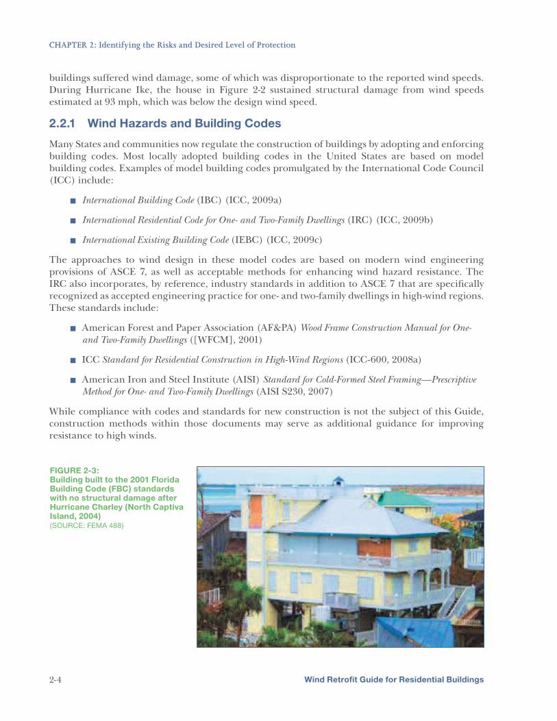
FIGURE 2-3: Building built to the 2001 Florida Building Code (FBC) standards with no structural damage after Hurricane Charley (North Captiva Island, 2004) (SOURCE: FEMA 488)
Wind Retrofit Guide for Residential Buildings 2-4
CHAPTER 2: Identifying the Risks and Desired Level of Protection
Building codes and standards are typically refined to incorporate lessons learned after natural disasters. Buildings like the one shown in Figure 2-3, built using modern wind engineering provisions incorporated in codes after Hurricane Andrew, performed better than older buildings during the 2004 hurricane season. The lack of a locally adopted code, or use of older codes, will likely increase the vulnerability of homes to wind damage.
As hurricanes continued to affect coastlines, more States, including Florida in 2001–2002, began adopting and mandating the use of nationally recognized codes and standards. Prior to Hurricane Katrina in 2005, Louisiana communities had varying building and residential codes, and in many communities, no established building codes at all. This lack of building codes, or use of older codes, is often an indicator that the houses in the area were designed and constructed without the modern hazard-resistance techniques that have been incorporated into newer building codes. To ensure that new buildings would perform better in future hurricanes, Louisiana mandated the use of the 2003 IRC and IBC, with State-specific amendments in 2007. This action was consistent with the recommendations in FEMA’s 2006 MAT report, FEMA 549, Hurricane Katrina in the Gulf Coast
(FEMA, 2006a).
2.2.2 Recommended Protection and Best Practices
Many mitigation or retrofit projects may be implemented to improve the performance of residential buildings in coastal regions, especially those buildings built to older codes. Section 2.2.1 discussed wind hazards and the building codes and standards that have been implemented over the years to help ensure that buildings perform adequately in their environment. As our knowledge of wind hazards has grown, our understanding of building performance has also changed, and so has the level of protection provided by a “code-compliant” building.
To improve the performance of a building in hurricane-prone regions, post-disaster investigations of impacted areas are conducted by FEMA, the building industry, and the insurance industry. Both independently and collaboratively, these groups have identified performance issues in older buildings. In general, the buildings that performed poorly did not have:
5 Roof and wall coverings capable of resisting high winds
5 Protection for openings (windows, doors, garage doors, soffits, and vents) to resist high winds, windborne debris, and wind-driven rain
5 Structural systems providing a continuous path for all loads (gravity, uplift, and lateral) to be passed from the building exterior surfaces to the ground through the foundation
This Guide presents Mitigation Packages that, if implemented correctly, will reduce the risks of damage to a residential building from a wind event. However, there are several factors to consider in the decision-making process to implement wind retrofit measures, such as:
5 Whether the house is a good candidate for a wind retrofit project
5 What Mitigation Packages are cost-effective for a house’s desired level of protection
5 How much risk of wind-related damage is acceptable to the homeowner
Based on observations
from previous post-disaster
investigations FEMA has
conducted, it is highly unlikely
that a single retrofit measure
alone will provide improved
protection and risk reduction
from a wind event. This Guide
presents groups of retrofit
measures in “packages” for a
more comprehensive solution
to risk reduction. The Mitigation
Packages are presented in
Chapter 4.
Wind Retrofit Guide for Residential Buildings 2-5
CHAPTER 2: Identifying the Risks and Desired Level of Protection
These factors and others are discussed in further detail in Chapters 3 and 4 of this Guide. It is important to understand that although the individual retrofit measures of the Mitigation Packages are based on design methods in current building codes and standards, not all of the design elements required by modern building codes for wind hazard resistance will be included in the retrofit project. Therefore, depending on the Mitigation Package(s) implemented, residual risk will likely still exist, even though some of the strengthened elements of the implemented retrofits may meet or exceed local building code requirements. More information on residual risk and addressing other hazards can be found in Section 5.3.
Implementing mitigation measures to reduce risk is a personal decision for homeowners to protect their house and property. Having made the decision to pursue a wind retrofit project, the homeowner will also have to decide what level of protection is desired. A homeowner’s decision regarding the desired level of protection will likely involve weighing the wind hazard risk with the cost of mitigating that risk. The FEMA BCA Tool can be used as a reference point for determining
being considered are cost-effective. Use of this software is required when submitting a grant application to one of FEMA’s HMA programs (refer to Chapter 5 and Appendix C). It should not, however, be the only factor used to make decisions regarding the wind retrofit project.
Each individual house is unique and exposed to risks that may be specific to a particular site or region. For example, implementing the Basic Mitigation Package may reduce risk, but may also leave too much residual risk; in this case, a homeowner may decide the additional cost of implementing the Intermediate Mitigation Package is more acceptable. Another cost consideration homeowners may face is the need to make improvements to their house before the Basic Mitigation Package described in this Guide can be implemented. Some houses may be previously damaged or may be undergoing improvements (addition or renovation). These houses may be candidates for a wind retrofit project, as components that are normally difficult to access may already be
whether the mitigation measures
exposed. However, such conditions may also trigger substantial improvement/substantial damage (SI/SD) provisions of governing building codes, requiring further work on the house outside the scope of the wind retrofit project type. See Section 5.2.1 for more information.
The wind retrofit Mitigation Packages described in this Guide are meant to improve the wind resistance of existing residential buildings. Retrofits described in this Guide should not be construed as providing protection comparable to that provided by safe rooms designed and constructed in accordance with FEMA 320, Taking Shelter from the Storm: Building a Safe Room for Your Home or Small
Business (Third Edition, 2008a) and FEMA 361, Design and Construction Guidance for Community
Safe Rooms (Second Edition, 2008b). Even where Mitigation Packages described in this Guide are implemented, evacuating hurricane-prone regions is still the best way to protect against injuries or loss of life during a hurricane event. Homeowners should always evacuate when told to do so by local or State authorities. If a homeowner’s ultimate goal of implementing a wind retrofit project is to protect building occupants from injury or death, FEMA recommends building a safe room. For additional information on safe rooms, see FEMA 320 and FEMA 361.
Wind Retrofit Guide for Residential Buildings
DETERMINING COST
EFFECTIVENESS
The FEMA BCA Tool
determines that a project
is cost-effective when the
benefit-cost ratio (BCR) is 1
or above. The software, along
with resource documents to
guide users through the BCA
process, can be downloaded
from www.bchelpline.com.
Appendix C provides a step-
by-step guide on using the
FEMA BCA Tool with the wind
retrofit packages presented in
this Guide.
2-6
For information on emergency storm prepartation, see "A Guide to Protecting Homes from Wind".
CHAPTER 2: Identifying the Risks and Desired Level of Protection
SAFE ROOMS: NEAR-ABSOLUTE PROTECTION
The level of occupant protection provided by a safe room is much
greater than the protection provided by buildings that comply with
the minimum requirements of most building codes or any level of
protection detailed in this Guide. Safe rooms offer near-absolute
protection (a very high probability of being protected from injury
or death). FEMA 320, Taking Shelter from the Storm: Building
a Safe Room for Your Home or Small Business (Third Edition,
2008a), includes prescriptive designs that provide homeowners
and their builders/contractors with information on how to construct
a safe room for a house. For solutions not covered by FEMA 320,
FEMA 361, Design and Construction Guidance for Community Safe
Rooms (Second Edition, 2008b), contains design criteria for custom
residential safe rooms.
Construction of a safe room in an existing house can be cost-effective
when the house undergoes a wind retrofit project, even though
construction of a safe room during new construction is typically
more cost-effective. Because safe rooms must have heavy, debris-
impact-resistant walls (constructed of reinforced concrete, reinforced
masonry, or wood with steel or masonry infill) that are secured to
the foundation, they are more difficult to construct in an existing
house. However, during a wind retrofit project for which walls, roofing
systems, and load path connections are being retrofitted, constructing
a safe room can be cost-effective. These retrofits are likely to occur
while the homeowner is attempting to achieve an Advanced Mitigation
Package designation. Installing a safe room during a retrofit helps
to economize the design staff, labor, and materials already under
contract and on site. For example, implementing the Advanced
Mitigation Package described in Chapter 4 typically requires
consultation with an engineer. If a homeowner is also considering
adding a safe room to an existing structure, it would be cost-effective
to include the safe room in the engineering consultation, whether or
not the consultation is required by local building codes.
FEMA continues to advocate for the design and construction of
residential safe rooms as evidenced by its continuing support of safe
room initiatives through several grant programs. Since the initiation
of its safe room program, FEMA has provided support for over
20,000 residential safe rooms with Federal funds totaling more than
$75,000,000 (as of FY 2010). A growing number of these safe rooms
have already saved lives in actual events. There have been no reported
failures of any safe room constructed to FEMA criteria.
Wind Retrofit Guide for Residential Buildings 2-7
CHAPTER 3
Evaluating Existing Homes
Retrofitting existing buildings has always been a potentially complicated task. Existing homes may be custom designed to complex shapes and configurations. Material types and construction methods can vary widely. Codes to which buildings were originally designed and
constructed can be well below modern requirements, and as previously mentioned, may even have been constructed in a location that had no adopted code at the time of construction. Therefore, in order to execute a successful retrofit on any home, an evaluation of its existing condition should be performed to determine:
5 Age and condition of the home
5 Overall structural integrity of the home
5 Weaknesses in the home’s envelope
5 Weaknesses in the home’s structure
5 Weaknesses in the home’s foundation
5 Whether the home can be retrofitted to effectively improve resistance to wind-related damage
5 How a home can be retrofitted for the different Mitigation Packages and how much each would cost
5 The most cost-effective retrofit project for the home
A qualified individual should evaluate the home and provide recommendations to the homeowner based on the findings. For the purposes of this Guide, this person will be referred to as an evaluator.
An acceptable evaluator should possess the level of residential building construction knowledge that meets the minimum requirements of a State or local wind mitigation program. Acceptable evaluators may include building science professionals such as registered architects and engineers, building officials, and evaluators that are certified through State or locally recognized wind retrofit programs (such as the IBHS FEH program).
3.1 Evaluating a Home
The purpose of the evaluation is to determine whether the home is a good candidate for any of the wind retrofit Mitigation Packages. It also serves to identify any repairs that must be performed
before a wind retrofit project can be undertaken and clarify the applicability of the wind retrofit Mitigation Packages from a construction standpoint. The evaluation will also identify whether
Wind Retrofit Guide for Residential Buildings 3-1
CHAPTER 3: Evaluating Existing Homes
prescriptive retrofits can be performed on the home or a specific engineering solution should be developed. The purpose of the evaluation is not to determine if the building meets current code.
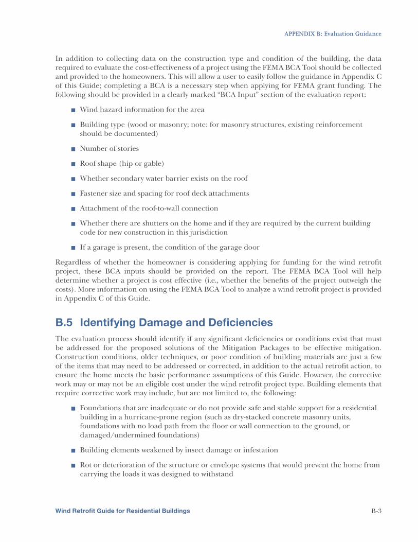
Before an evaluation is performed, homeowners should compile any available documentation on the design and construction of the home. Where available, the following information should be provided to the evaluator:
5 Documentation regarding the foundation of the building
5 Documentation regarding the existing roof covering
÷ If the roof covering has not been replaced, the purchase contract, building permit, or property tax record showing the age of the property
÷ If at least a portion of the roof covering has been replaced, a copy of the work order for the roofing or a receipt for its installation
5 If a secondary water barrier (SWB) has been installed on the roof, a receipt for its installation
5 If a termite inspection has been conducted within 12 months on the home, the termite inspection report or bond issued
5 Documentation regarding windows, entry doors, garage doors, and impact-rated products (such as shutters systems)
÷ Owner’s manuals
÷ Original labels
÷ Any form of verification that they are impact-rated, if applicable
5 If insulating foam has been applied to the underside of the roof deck, information on the foam product used
5 Any additional documentation regarding the condition of the building or prior work done to the building, such as design plans or inspection reports
5 Photographic documentation of the building and any improvements (such as previous work performed, renovations, or deck construction)
Having all available information prepared for the evaluator when he/she arrives can greatly increase the accuracy and timeliness of the evaluation. When the evaluation begins, homeowners (and other parties involved in the decision-making process) should have an idea of which Mitigation Package they will implement based on available budget, perceived condition and age of the home, cost-effectiveness of retrofits, Federal assistance, and other savings. The evaluator should be able to provide preliminary advice on which Mitigation Package to consider; this can be discussed before the evaluation begins. The selected Mitigation Package will affect how invasive the evaluation will be. The evaluator should conduct a full walkthrough of the home, assessing the condition of the areas that will be retrofitted as well as the overall condition of the home. For example, if there are significantly damaged components within the roof system, the evaluator should provide a detailed description of the damage in the evaluation report, including a description of any needed repairs required before the home is a suitable wind retrofit project candidate and whether those repairs will require a professional engineer’s consultation.
Wind Retrofit Guide for Residential Buildings 3-2
CHAPTER 3: Evaluating Existing Homes
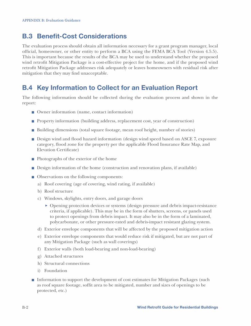
The following sections discuss the evaluation process for the building envelope and structure. Additional guidance on evaluating buildings before starting a wind retrofit project, including what should be documented in the building evaluation, is presented in Appendix B of this Guide.
3.1.1 Basic and Intermediate Package Evaluations
For projects implementing the Basic or Intermediate Package, the evaluation should focus mainly on the building envelope. The following building elements should be inspected and their material type and existing condition documented during the evaluation:
5 Roof system (the roof covering and roof structural system beneath)
5 Attic ventilation systems (soffits, ridge, off-ridge, and gable end vents)
5 Wall systems (wall framing and coverings, including gable end walls)
5 Openings (windows, skylights, entry doors, and garage doors)
5 Attached structures (porches, awnings, and carports)
Evaluation of these building elements for the Basic and Intermediate Packages will usually involve only minimal disturbance to the building during the evaluation.
The evaluation of the roof covering will determine whether the roof covering needs to be replaced as part of the wind retrofit project. A home with a roof covering assessed as having 5 or more years of remaining useful life is a candidate for retrofit options that do not require roof covering replacement. To determine the remaining useful life of the roof covering, the evaluator should use any available documentation provided by the homeowner as well as visual observations of the roof covering condition. When evaluating the roof structure, the attic will need to be accessed in most cases. The evaluator should use a handheld metal-detecting scanner to assess the existing roof deck attachments without removing the roof covering or using other invasive measures.
The evaluator should also verify whether the home already has completed any of the retrofit projects including in the Mitigation Packages. For example, a home being evaluated may already have window protection that meets the opening protection requirements of the Intermediate or Advanced Mitigation Package. The evaluator should verify that the opening protection (e.g., shutters over openings or pressure- and impact-rated windows and doors) provides the level of protection for the respective Mitigation Package as defined in Chapter 4 of this Guide, and is in a satisfactory condition (e.g., shutters are functional and are properly anchored to the building). In the case of opening protection, this is typically verified through labeling or documentation the homeowner may have for the product(s), as shown in Figure 3-1. Identifying whether the house already has any completed retrofit projects will increase the cost-effectiveness of the overall mitigation effort.
The evaluation will include an
assessment of the existing
roof covering. While the
homeowner may already know
whether he or she wants to
replace the roof covering, the
evaluation will identify whether
the roof covering is in need of
replacement.
Wind Retrofit Guide for Residential Buildings 3-3
CHAPTER 3: Evaluating Existing Homes
FIGURE 3-1: Example of a window product label
3.1.2 Advanced Package Evaluations
Providing a continuous load path is a part of the Advanced Mitigation Package, but not part of the Basic or Intermediate Mitigation Packages. For the Advanced Mitigation Package, the structural connections that create a continuous load path from the roof to the foundation need to be evaluated.
The evaluator will need to identify any locations where the continuous load path is broken. Some controlled, destructive actions may be necessary to access structural connections. The level of invasiveness of an assessment for the Advanced Mitigation Package will depend on the construction type and structural configuration of the home.
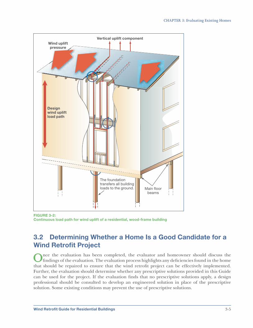
A continuous load path is an important part of a building’s ability to resist wind-related damage. The continuous load path ensures that loads applied to any part of the building can be transferred through the building from the point of application (such as the roof or exterior walls) through the structure of the building and to the foundation (see Figure 3-2). A home for which the Advanced Mitigation Package is being sought does
not have to have an existing continuous load path before the wind retrofit project is performed. However, having fewer adequate structural connections capable of transferring design wind loads usually correlates to higher costs when retrofitting the home to the Advanced Mitigation Package.
Wind Retrofit Guide for Residential Buildings
Regardless of which Mitigation
Package is chosen, the
evaluation should cover the
entire building envelope and look
for conditions that would limit
the effectiveness of the wind
retrofit project. For example, if
the wall covering is deteriorated,
damaged, or not sufficiently
fastened to the building,
performing a wind retrofit would
not provide the intended level of
protection.
3-4
CHAPTER 3: Evaluating Existing Homes
Wind Retrofit Guide for Residential Buildings
FIGURE 3-2: Continuous load path for wind uplift of a residential, wood-frame building
3.2 Determining Whether a Home Is a Good Candidate for a
Wind Retrofit Project
Once the evaluation has been completed, the evaluator and homeowner should discuss the findings of the evaluation. The evaluation process highlights any deficiencies found in the home
that should be repaired to ensure that the wind retrofit project can be effectively implemented. Further, the evaluation should determine whether any prescriptive solutions provided in this Guide can be used for the project. If the evaluation finds that no prescriptive solutions apply, a design professional should be consulted to develop an engineered solution in place of the prescriptive solution. Some existing conditions may prevent the use of prescriptive solutions.
3-5
CHAPTER 3: Evaluating Existing Homes
The following conditions, if found to exist in the home being evaluated, would preclude the home from prescriptive criteria in this Guide:
5 Roof framing with:
÷ Spacing greater than 24 inches on-center (o.c.)
÷ Members less than nominal 2 inches
5 Roof slope less than 2/12
5 Roof deck panels less than nominal 7/16-inch thickness (for wood structural panels)
5 Gable end walls with:
÷ Structural panels less than nominal 7/16-inch thickness (or no structural panels)
÷ Heights greater than 16 feet
5 Rooftop equipment that adds significant dead load to the roof
Although any home can be mitigated, it may be in such poor condition, may have been damaged, or may have an existing condition that must be addressed for any of the proposed Mitigation Packages to be effective. In these instances, additional work may be needed before, or during, the wind retrofit project. This does not mean that such a home cannot undergo wind retrofits in accordance with this Guide, but additional effort would likely need to be expended before the home can be considered a good candidate for one of the Mitigation Packages presented in this Guide.
The outcome of the evaluation should be a report describing the evaluator’s findings. The report should include a description of the existing condition of the building and a recommendation of one or more of the Mitigation Packages. If repairs are needed before the wind retrofit project can
proceed, a general assessment of the work required should be provided. Some conditions, if found to exist in the home, can require extensive and invasive work and have very high associated costs. Appendix B contains further guidance on such situations.
In contrast, some homes may already incorporate some of the elements of the Mitigation Packages even before the retrofit process has begun. In this situation, the evaluator should verify that the existing components of the building are in accordance with the retrofits defined for the selected Mitigation Package.
It should not be assumed that an evaluator will provide a cost estimate, but doing so in coordination with the evaluation
report facilitates the decision-making process for the homeowner. The evaluation report should be detailed enough for an individual with an appropriate level of building science knowledge to use it to prepare a basic cost estimate. The cost estimate should be detailed enough to provide the homeowner and other decision-making parties with enough costing information to make a decision in most cases, but for a more complete estimate, it may be necessary to obtain cost estimates from building contractors. Based on the findings of the evaluation process, the report should result in one of three determinations:
Wind Retrofit Guide for Residential Buildings
The evaluation for a wind
retrofit project may identify
existing conditions that need
to be remedied. Performing
repairs while undergoing a wind
retrofit project may be cost-
effective. Chapter 5 provides
further information on repair/
improvement situations, as well
as guidance on Federal grant
funding.
3-6
CHAPTER 3: Evaluating Existing Homes
1. The prescriptive solutions in this Guide may be used for the retrofit projects. The report should identify which projects of the selected Mitigation Package can be implemented using prescriptive solutions.
2. Some of the construction elements of the retrofit projects for the Mitigation Package are already present in the home. The report should identify which portions of the home already accomplish which items of the selected Mitigation Package, and how the remainder of the items can be addressed.
3. The prescriptive solutions in this Guide cannot be used because there are existing building conditions that differ from those assumed for this Guide; therefore, at least some portion of the wind retrofit project cannot be implemented as presented in this Guide without additional effort. A registered design professional should develop a solution for retrofits to any building elements for which prescriptive solutions cannot be used.
Homes that fall under one of the first two determinations are typically the most cost-effective candidates, as less site-specific design work is needed. The third determination typically occurs when a home has a condition for which the prescriptive solutions in this Guide cannot be applied.
3.3 Deciding What Level of Protection to Achieve
Buildings are not constructed to resist all damage from hazard events. Homeowners must decide what level of risk is acceptable to them. The cost of the wind retrofit project undertaken must
be weighed against the potential of losses due to wind-related damages and higher insurance premiums. Doing no work on an existing building that is not well protected from wind-related damages represents high risk and high insurance premiums (but no associated project costs), while doing extensive work to retrofit a home as much as possible from wind-related damages represents a resulting lower risk and lower insurance premiums (but higher associated retrofitting costs). The mitigation presented in this Guide provides intermediate levels of protection and associated cost. It is important to remember that, whether a home is constructed beyond the minimum requirements of building codes or is being retrofitted to improve its hazard resistance, the homeowner must decide what level of risk from high-wind events is acceptable.
Once an evaluation has been performed, the homeowner—in consultation with the evaluator— should make a final decision on the desired level of protection to achieve by the retrofits. Each level of the three Mitigation Packages described in this Guide—Basic, Intermediate, and Advanced— provides increasing resistance to wind-related damage; each level of protection can only be achieved if the retrofit projects included in the lower levels have been implemented. For instance, the level of protection provided by the Advanced Mitigation Package can only be met if the projects included in both Basic and Intermediate Mitigation Packages have been implemented.
Different buildings will be better suited to different levels of retrofitting. Newer buildings that are built to more recent codes and standards may be easier to retrofit to the Advanced Mitigation Package level of protection. As discussed in Section 3.1, some buildings may even already meet one or more of the levels of mitigation described in this Guide. Further, a home may meet some of the criteria of one or more of the Mitigation Packages, and implementing the remaining retrofit projects may be a cost-effective solution. On the other hand, retrofitting an older building to provide a continuous load path, as required when applying the Advanced Mitigation Package, may not be cost effective.
Wind Retrofit Guide for Residential Buildings 3-7
CHAPTER 3: Evaluating Existing Homes
When considering whether to undertake a retrofit project, homeowners should consider all of the benefits and costs of the project. The benefits and costs associated with implementing a wind retrofit project should be effectively conveyed by the evaluator and well understood by the homeowner before a decision is made. Some factors to consider when understanding the costs and benefits include the following:
Costs
The total cost for the wind retrofit project. The cost of the project is often the primary factor when determining whether to undertake a wind retrofit project and which Mitigation Package to implement. The project cost will be affected by several factors, one of which is whether the prescriptive solutions of this Guide are applicable for the project. If prescriptive solutions cannot be used for the project, then the services of a design professional will need to be obtained to develop specific solutions. This may result in higher costs for the project. Other factors that affect the project cost are the level of protection chosen (i.e., which Mitigation Package will be implemented) and the location of the home (which can affect opening protection and design wind speed requirements).
Compliance with codes and local building departments. Modern building codes contain provisions for existing buildings that, when triggered by proposed work on the home, may require additional work. Similarly, requirements of local building departments can vary, and in some circumstances can place additional requirements on the wind retrofit project process. The evaluator should have a good understanding of the applicable building code provisions and local permitting and inspection requirements, because these are often specific to the community in which the project is being performed. Section 5.2 further discusses these issues.
Effects of construction. When considering a wind retrofit project, homeowners should consider that they may be displaced for a short time. While the displacement may not last long, there are costs and other obstacles associated with being displaced that the homeowner should take into account, even if it is only for a few days.
Benefits
Damage resistance. The reduction in anticipated damages for retrofitted houses is a quantifiable benefit to society and the individual. Homes that survive high-wind events achieve the benefits of avoided building damages, reduced damage to building contents, and reduced or no displacement of the occupants. When a BCA is performed for a home undergoing a wind retrofit project, these benefits are taken into account to determine the cost effectiveness of the project.
Wind hazard insurance plans and premiums. Homes in areas prone to high-wind events generally have homeowners’ insurance policies that include coverage for wind damage. For these homes, risk-based premiums should account for the higher risk the home faces due to its location, as well as the increased likelihood and greater severity of losses after frequent high-wind events. Many insurance companies encourage their policyholders to retrofit their homes to resist wind-related damage, and some companies have established discount programs to reduce premiums, or other types of financial incentives, to reflect the risk reduction for homes that have been properly retrofitted. Some State insurance departments
Wind Retrofit Guide for Residential Buildings 3-8
CHAPTER 3: Evaluating Existing Homes
also have put in place insurance discount programs for properly retrofitted homes. The IBHS FEH program has been designed with the support of IBHS member insurance companies, although each individual company makes its own decisions about how it is implemented.
Federal assistance through HMA grant programs. As described in Chapter 5, homeowners can obtain Federal funding assistance for hazard mitigation projects. Through FEMA’s HMA grant programs, applications for an individual home or groups of homes undergoing wind retrofit projects can be submitted for approval. If applications are approved, Federal funding is provided for 75 percent of the total project cost, significantly reducing the homeowner’s expenses for the project. The remaining 25 percent of eligible project costs can be paid for directly, or covered by donated labor, time, and materials. Consult FEMA’s HMA Unified Guidance for more details on cost sharing. More information on Federal assistance through HMA programs can be found in Chapter 5.
Homeowners should consider both qualitative and quantitative benefits and costs when deciding on a wind retrofit project. To apply for Federal assistance through HMA programs (as described in Chapter 5), an analysis or comparison of the benefits to society compared to the cost of the project must be conducted. Benefits such as reduced insurance premiums are not considered in the equation because they are an individual benefit. To assist in the process of calculating the quantitative benefits and costs, the FEMA BCA Tool was created to provide a consistent approach for this determination (refer to Appendix C for additional information on using the FEMA BCA Tool). Communities are encouraged to use the software, regardless of whether they will apply for Federal funding or not. The software will calculate benefits gained by performing the project, such as avoided damage to the home, avoided displacement costs, and avoided loss of building contents. The evaluation report discussed in Section 3.2 should identify all of the necessary input data needed for using the FEMA BCA Tool. Appendix C provides a step-by-step guide to using the FEMA BCA Tool to evaluate the cost effectiveness of a wind retrofit project.
Wind Retrofit Guide for Residential Buildings 3-9
Wind Retrofit Guide for Residential Buildings 4-1
CHAPTER 4
Technical Design and
Construction Methods
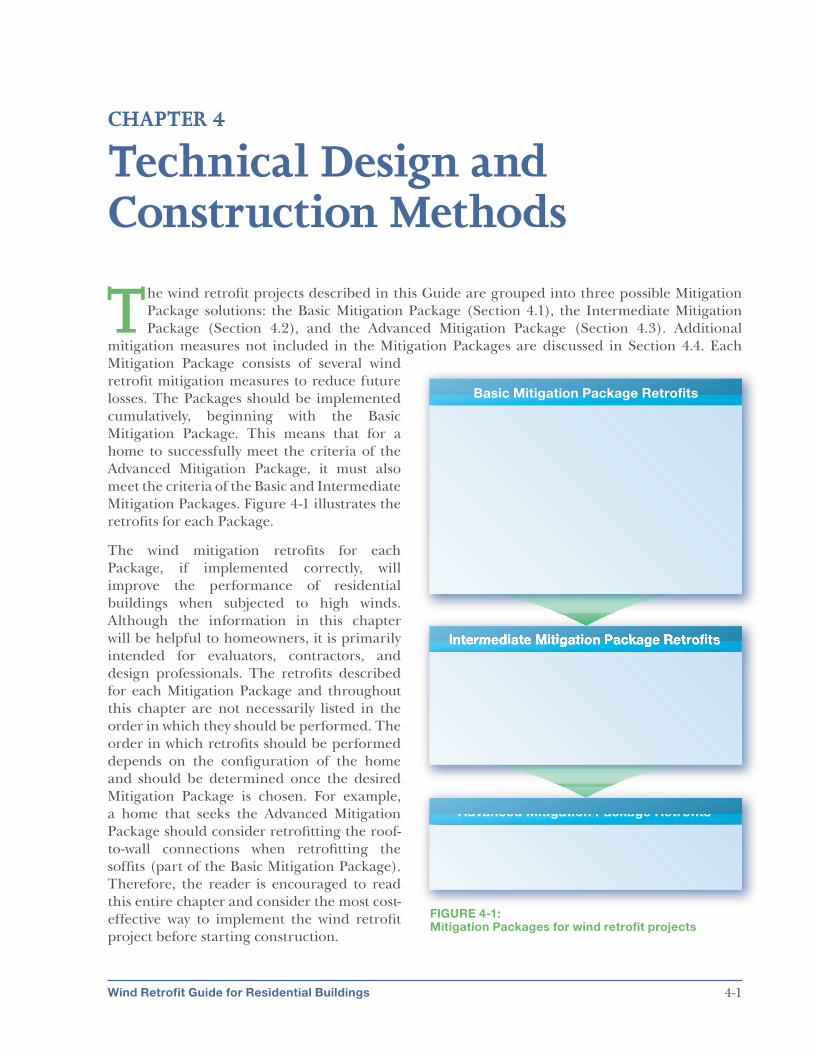
The wind retrofit projects described in this Guide are grouped into three possible Mitigation Package solutions: the Basic Mitigation Package (Section 4.1), the Intermediate Mitigation Package (Section 4.2), and the Advanced Mitigation Package (Section 4.3). Additional
mitigation measures not included in the Mitigation Packages are discussed in Section 4.4. Each Mitigation Package consists of several wind retrofit mitigation measures to reduce future losses. The Packages should be implemented cumulatively, beginning with the Basic Mitigation Package. This means that for a home to successfully meet the criteria of the Advanced Mitigation Package, it must also meet the criteria of the Basic and Intermediate Mitigation Packages. Figure 4-1 illustrates the retrofits for each Package.
The wind mitigation retrofits for each Package, if implemented correctly, will improve the performance of residential buildings when subjected to high winds. Although the information in this chapter will be helpful to homeowners, it is primarily intended for evaluators, contractors, and design professionals. The retrofits described for each Mitigation Package and throughout this chapter are not necessarily listed in the order in which they should be performed. The order in which retrofits should be performed depends on the configuration of the home and should be determined once the desired Mitigation Package is chosen. For example, a home that seeks the Advanced Mitigation Package should consider retrofitting the roof-to-wall connections when retrofitting the soffits (part of the Basic Mitigation Package). Therefore, the reader is encouraged to read this entire chapter and consider the most cost-
FIGURE 4-1: Mitigation Packages for wind retrofit projects
effective way to implement the wind retrofit project before starting construction.
CHAPTER 4: Technical Design and Construction Methods
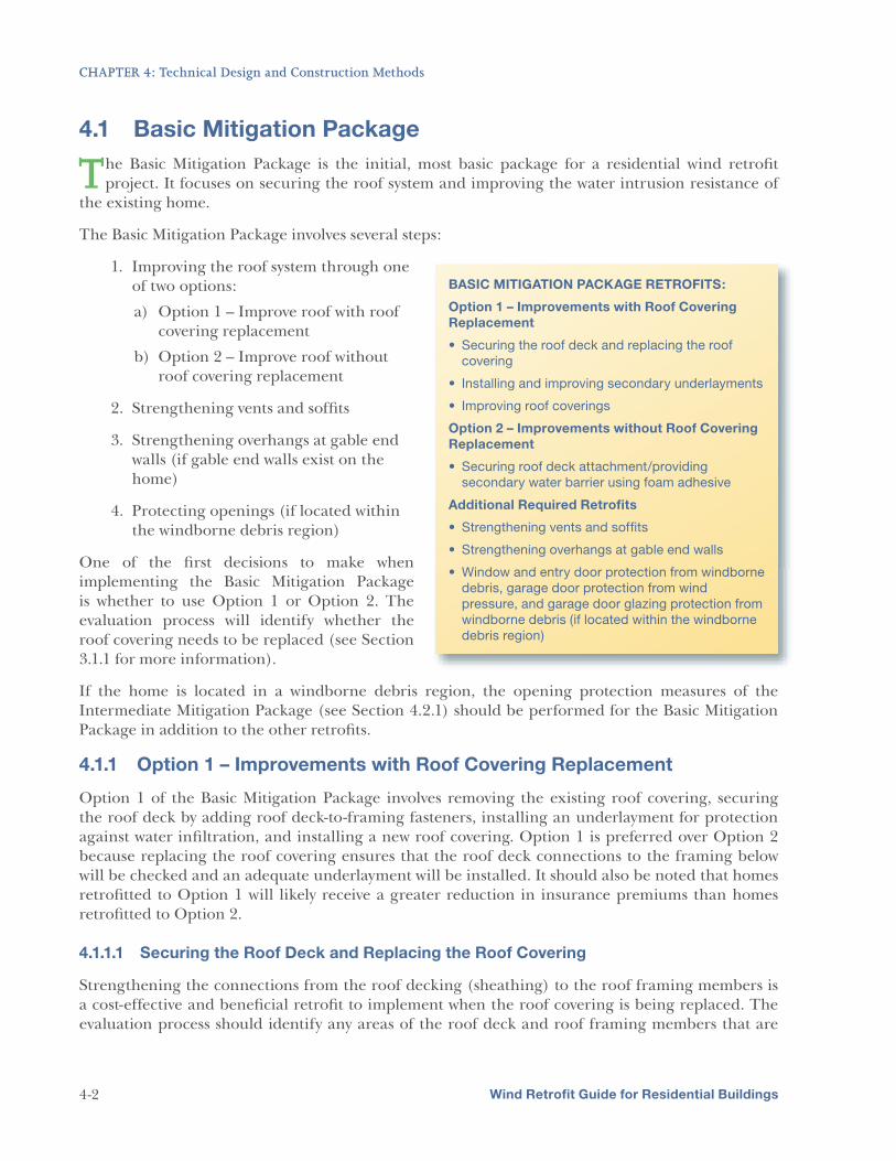
4.1 Basic Mitigation Package
The Basic Mitigation Package involves several steps:
The Basic Mitigation Package is the initial, most basic package for a residential wind retrofit project. It focuses on securing the roof system and improving the water intrusion resistance of
the existing home.
1. Improving the roof system through one of two options:
a) Option 1 – Improve roof with roof covering replacement
b) Option 2 – Improve roof without roof covering replacement
2. Strengthening vents and soffits
3. Strengthening overhangs at gable end walls (if gable end walls exist on the home)
4. Protecting openings (if located within the windborne debris region)
One of the first decisions to make when implementing the Basic Mitigation Package is whether to use Option 1 or Option 2. The evaluation process will identify whether the roof covering needs to be replaced (see Section 3.1.1 for more information).
BASIC MITIGATION PACKAGE RETROFITS:
Option 1 – Improvements with Roof Covering
Replacement
covering
Option 2 – Improvements without Roof Covering
Replacement
secondary water barrier using foam adhesive
Additional Required Retrofits
debris, garage door protection from wind
pressure, and garage door glazing protection from
windborne debris (if located within the windborne
debris region)
If the home is located in a windborne debris region, the opening protection measures of the Intermediate Mitigation Package (see Section 4.2.1) should be performed for the Basic Mitigation Package in addition to the other retrofits.
4.1.1 Option 1 – Improvements with Roof Covering Replacement
Option 1 of the Basic Mitigation Package involves removing the existing roof covering, securing the roof deck by adding roof deck-to-framing fasteners, installing an underlayment for protection against water infiltration, and installing a new roof covering. Option 1 is preferred over Option 2 because replacing the roof covering ensures that the roof deck connections to the framing below will be checked and an adequate underlayment will be installed. It should also be noted that homes retrofitted to Option 1 will likely receive a greater reduction in insurance premiums than homes retrofitted to Option 2.
4.1.1.1 Securing the Roof Deck and Replacing the Roof Covering
Strengthening the connections from the roof decking (sheathing) to the roof framing members is a cost-effective and beneficial retrofit to implement when the roof covering is being replaced. The evaluation process should identify any areas of the roof deck and roof framing members that are
Wind Retrofit Guide for Residential Buildings 4-2
CHAPTER 4: Technical Design and Construction Methods
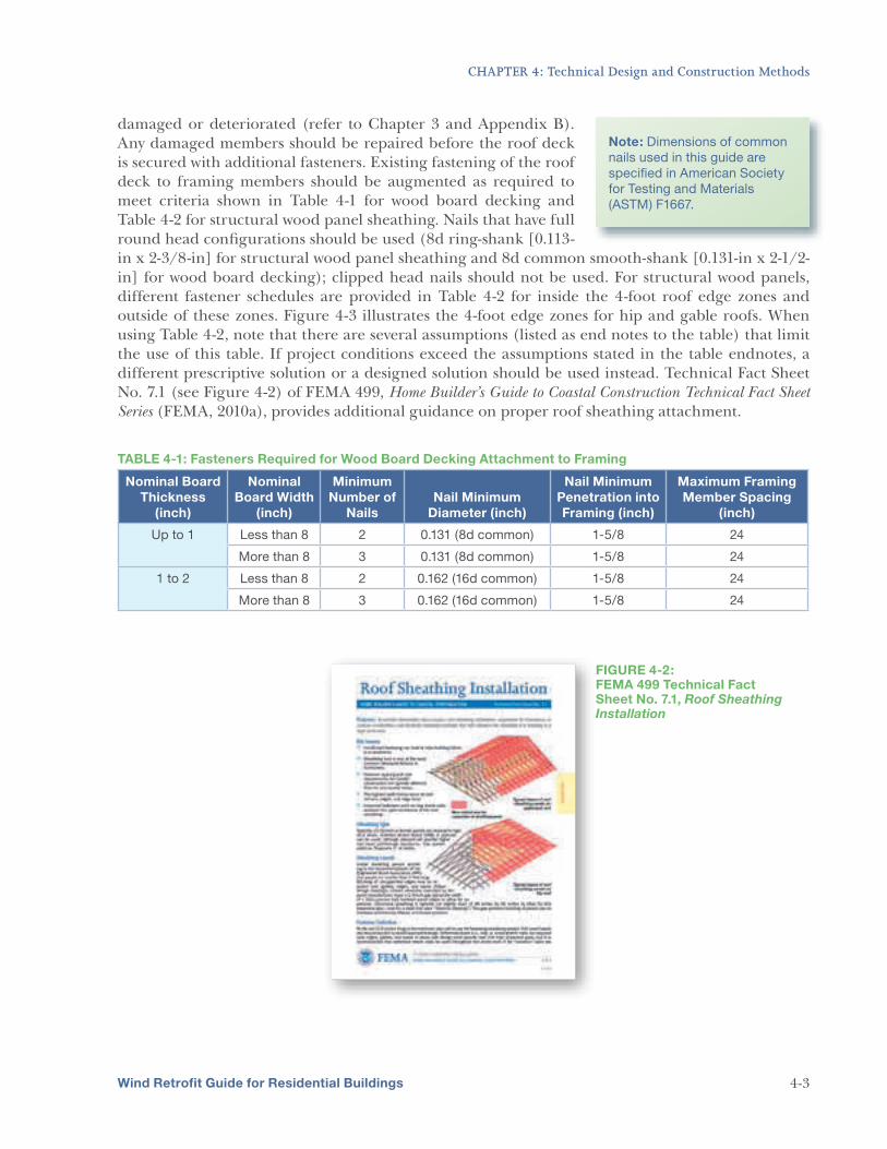
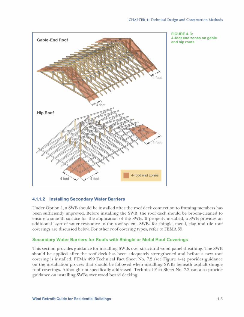
damaged or deteriorated (refer to Chapter 3 and Appendix B). Any damaged members should be repaired before the roof deck is secured with additional fasteners. Existing fastening of the roof deck to framing members should be augmented as required to meet criteria shown in Table 4-1 for wood board decking and Table 4-2 for structural wood panel sheathing. Nails that have full round head configurations should be used (8d ring-shank [0.113-in x 2-3/8-in] for structural wood panel sheathing and 8d common smooth-shank [0.131-in x 2-1/2-in] for wood board decking); clipped head nails should not be used. For structural wood panels, different fastener schedules are provided in Table 4-2 for inside the 4-foot roof edge zones and outside of these zones. Figure 4-3 illustrates the 4-foot edge zones for hip and gable roofs. When using Table 4-2, note that there are several assumptions (listed as end notes to the table) that limit the use of this table. If project conditions exceed the assumptions stated in the table endnotes, a different prescriptive solution or a designed solution should be used instead. Technical Fact Sheet No. 7.1 (see Figure 4-2) of FEMA 499, Home Builder’s Guide to Coastal Construction Technical Fact Sheet
Series (FEMA, 2010a), provides additional guidance on proper roof sheathing attachment.
Note: Dimensions of common
nails used in this guide are
specified in American Society
for Testing and Materials
(ASTM) F1667.
TABLE 4-1: Fasteners Required for Wood Board Decking Attachment to Framing
smooth shank o.c. between existing and between existing and
nails (0.131-in added fasteners along additional fasteners
x 2-1/2-in) panel edges; 6-inch o.c.
spacing between additional
fasteners along intermediate
framing
along panel edges and
intermediate framing
8d ring shank 12 inches 6-inch o.c. spacing between 6-inch o.c. spacing
nails (0.113-in o.c. or less existing and additional between existing and
x 2-3/8-in) fasteners along panel edges
and intermediate framing
additional fasteners
along panel edges and
intermediate framing
Staples or 6d
common nails
(0.113-in x
2-in)
Any 4-inch o.c. spacing between
added fasteners along panel
edges and intermediate
framing
6-inch o.c. spacing
between added fasteners
along panel edges and
intermediate framing
8d common < 6 inches 4-inch o.c. spacing between No additional fasteners
smooth shank o.c. existing and added required along panel
nails (0.131-in fasteners along panel edges; 6-inch o.c. spacing
>120 and >155 and
x 2-1/2-in) edges; 6-inch o.c. between
additional fasteners along
intermediate framing
between added fasteners
along intermediate
framing
8d common 6 inches 4-inch o.c. spacing between 6-inch o.c. spacing 150 194 smooth shank o.c. existing and added between existing and
nails (0.131-in fasteners along panel edges added fasteners along
x 2-1/2-in) and intermediate framing panel edges; 6-inch
o.c. spacing between
added fasteners along
intermediate framing
8d ring shank 12 inches 4-inch o.c. spacing between 6-inch o.c. spacing
nails (0.113-in o.c. existing and added between existing
x 2-3/8-in) fasteners along panel edges
and intermediate framing
and added fasteners
along panel edges and
intermediate framing
Notes:
Minimum nominal 7/16 in. thickness wood structural panel sheathing.
Wind Exposure Category: Exposure C.
Mean roof height not to exceed 30 feet.
Roof framing specific gravity, G, not less than 0.55 (southern pine).
See Figure 4-3 for identification of 4-foot zone on roof.
Wind Retrofit Guide for Residential Buildings 4-4
CHAPTER 4: Technical Design and Construction Methods
FIGURE 4-3: 4-foot end zones on gable and hip roofs
4.1.1.2 Installing Secondary Water Barriers
Under Option 1, a SWB should be installed after the roof deck connection to framing members has been sufficiently improved. Before installing the SWB, the roof deck should be broom-cleaned to ensure a smooth surface for the application of the SWB. If properly installed, a SWB provides an additional layer of water resistance to the roof system. SWBs for shingle, metal, clay, and tile roof coverings are discussed below. For other roof covering types, refer to FEMA 55.
Secondary Water Barriers for Roofs with Shingle or Metal Roof Coverings
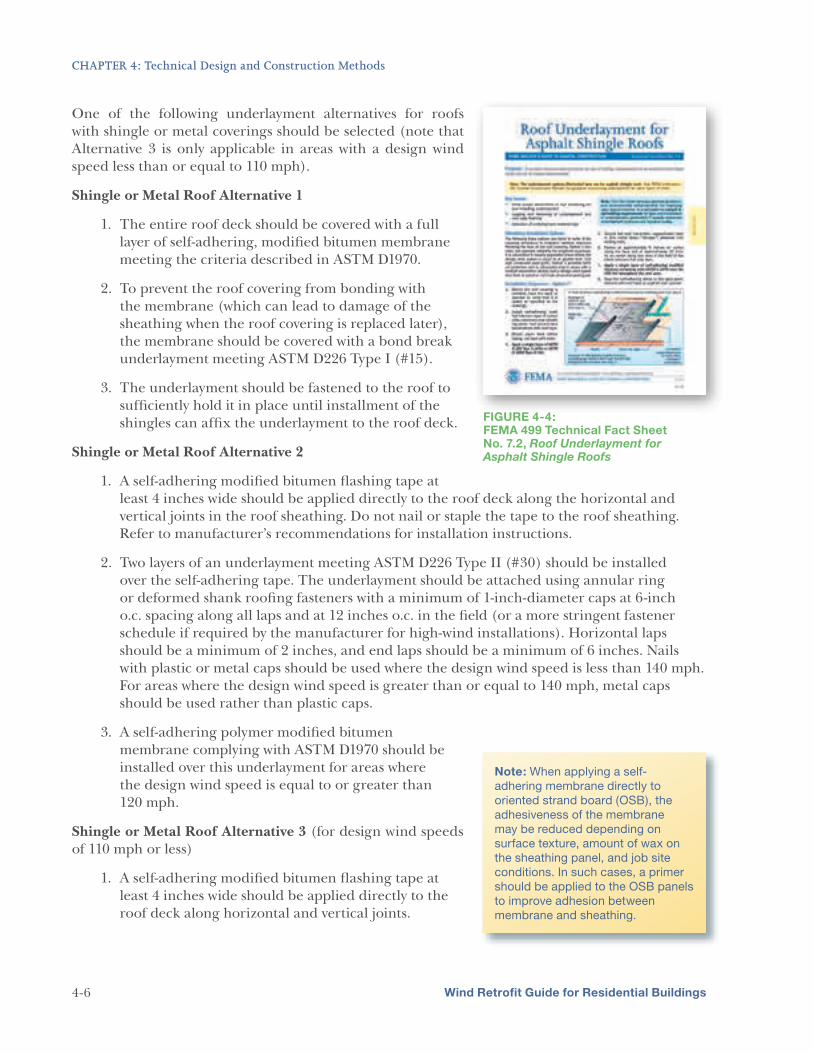
This section provides guidance for installing SWBs over structural wood panel sheathing. The SWB should be applied after the roof deck has been adequately strengthened and before a new roof covering is installed. FEMA 499 Technical Fact Sheet No. 7.2 (see Figure 4-4) provides guidance on the installation process that should be followed when installing SWBs beneath asphalt shingle roof coverings. Although not specifically addressed, Technical Fact Sheet No. 7.2 can also provide guidance on installing SWBs over wood board decking.
Wind Retrofit Guide for Residential Buildings 4-5
CHAPTER 4: Technical Design and Construction Methods
One of the following underlayment alternatives for roofs with shingle or metal coverings should be selected (note that Alternative 3 is only applicable in areas with a design wind speed less than or equal to 110 mph).
Shingle or Metal Roof Alternative 1
1. The entire roof deck should be covered with a full layer of self-adhering, modified bitumen membrane meeting the criteria described in ASTM D1970.
2. To prevent the roof covering from bonding with the membrane (which can lead to damage of the sheathing when the roof covering is replaced later), the membrane should be covered with a bond break underlayment meeting ASTM D226 Type I (#15).
3. The underlayment should be fastened to the roof to sufficiently hold it in place until installment of the shingles can affix the underlayment to the roof deck. FIGURE 4-4:
1. A self-adhering modified bitumen flashing tape at least 4 inches wide should be applied directly to the roof deck along the horizontal and vertical joints in the roof sheathing. Do not nail or staple the tape to the roof sheathing. Refer to manufacturer’s recommendations for installation instructions.
2. Two layers of an underlayment meeting ASTM D226 Type II (#30) should be installed over the self-adhering tape. The underlayment should be attached using annular ring or deformed shank roofing fasteners with a minimum of 1-inch-diameter caps at 6-inch o.c. spacing along all laps and at 12 inches o.c. in the field (or a more stringent fastener schedule if required by the manufacturer for high-wind installations). Horizontal laps should be a minimum of 2 inches, and end laps should be a minimum of 6 inches. Nails with plastic or metal caps should be used where the design wind speed is less than 140 mph. For areas where the design wind speed is greater than or equal to 140 mph, metal caps should be used rather than plastic caps.
3. A self-adhering polymer modified bitumen membrane complying with ASTM D1970 should be installed over this underlayment for areas where the design wind speed is equal to or greater than 120 mph.
Shingle or Metal Roof Alternative 3 (for design wind speeds of 110 mph or less)
1. A self-adhering modified bitumen flashing tape at least 4 inches wide should be applied directly to the roof deck along horizontal and vertical joints.
Note: When applying a self-
adhering membrane directly to
oriented strand board (OSB), the
adhesiveness of the membrane
may be reduced depending on
surface texture, amount of wax on
the sheathing panel, and job site
conditions. In such cases, a primer
should be applied to the OSB panels
to improve adhesion between
membrane and sheathing.
Wind Retrofit Guide for Residential Buildings 4-6
CHAPTER 4: Technical Design and Construction Methods
2. A single layer of ASTM D226 Type I (#15) or ASTM D4869 Type II felt should be installed over the self-adhering tape. The underlayment should be held in place using tacks before shingles are applied.
Secondary Underlayments for Concrete and Clay Tile Roofs
For concrete and clay tile roofs, one of the following underlayment alternatives should be followed.
Tile Roof Alternative 1
1. The entire roof deck should be covered with a full layer of self-adhering polymer modified bitumen membrane meeting ASTM D1970. Note that some local building departments, such as Miami-Dade and Broward Counties in Florida, prohibit the use of this system. The local building department should be consulted before implementing this alternative.
Tile Roof Alternative 2
1. Self-adhering modified bitumen flashing tape at least 4 inches wide should be applied directly to the roof deck along horizontal and vertical joints in the roof sheathing. Do not nail or staple the tape to the roof sheathing. Refer to the underlayment manufacturer’s recommendations for installation instructions.
2. An underlayment meeting ASTM D226 Type II (#30) should be installed over the self-adhering tape. The underlayment should be attached using annular ring or deformed shank roofing fasteners with a minimum of 1-inch-diameter caps at 6-inch o.c. spacing along all laps and at 12 inches o.c. in the field (or a more stringent fastener schedule if required by the manufacturer for high-wind installations). Horizontal laps should be a minimum of 2 inches, and end laps should be a minimum of 6 inches. Nails with plastic or metal caps should be used only where the design wind speed is less than 140 mph. Only metal caps should be used for areas where the design wind speed is greater than or equal to 140 mph.
3. A self-adhering polymer modified bitumen membrane complying with ASTM D1970 should be installed over this underlayment.
Tile Roof Alternative 3
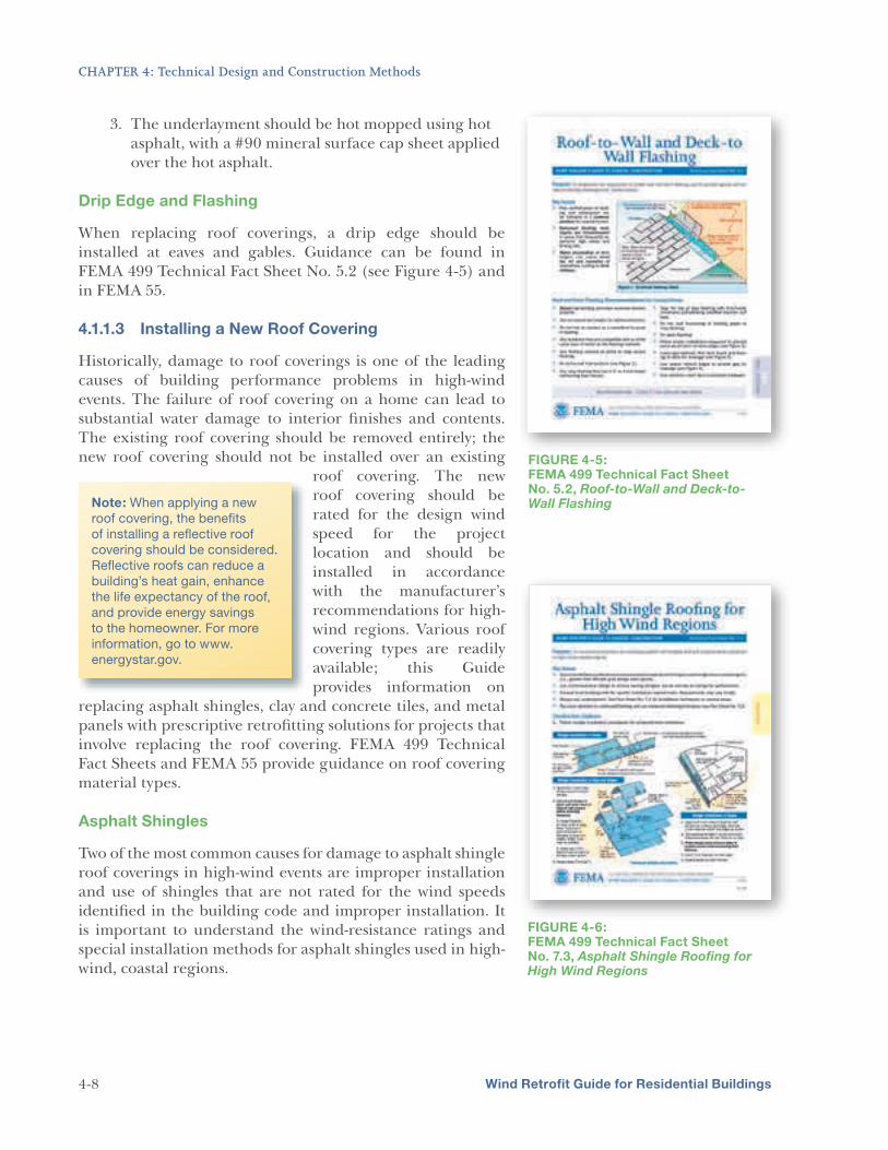
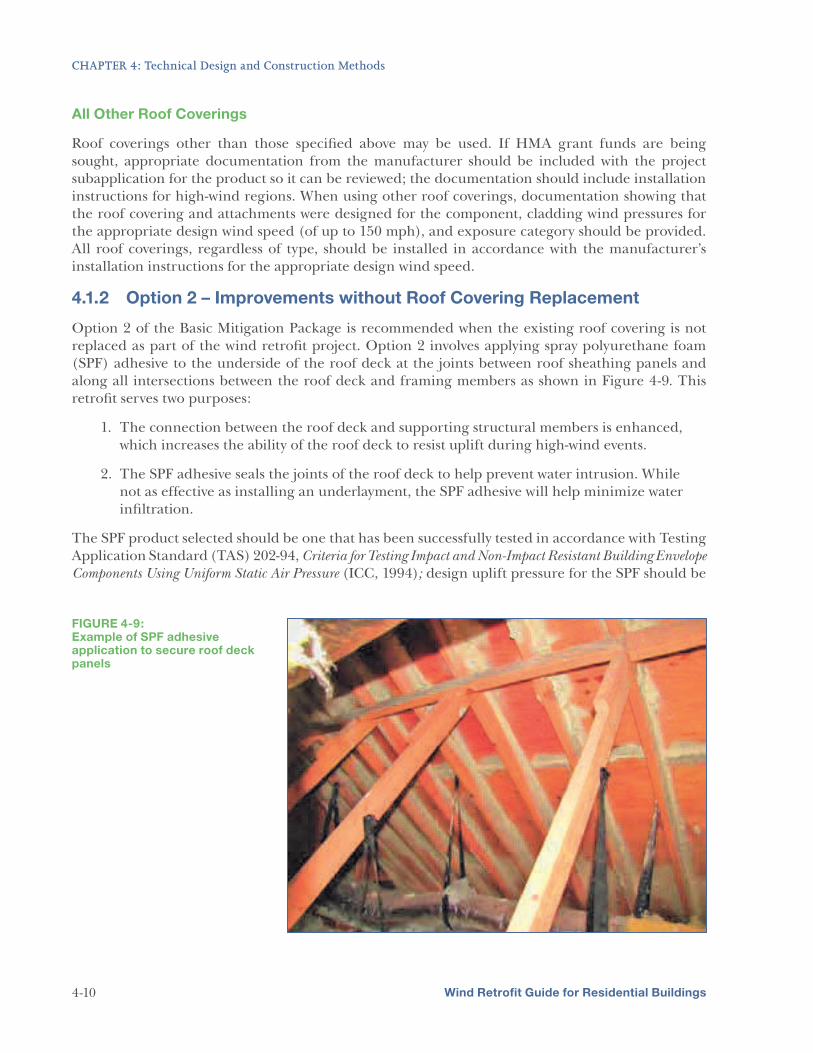
4-7
1. A self-adhering modified bitumen flashing tape at least 4 inches wide should be applied directly to the roof deck along horizontal and vertical joints in the roof sheathing.
2. An underlayment meeting ASTM D226 Type II (#30) should be installed over the self-adhering tape. The underlayment should be attached using annular ring or deformed shank roofing fasteners with a minimum of 1-inch-diameter caps at 6-inch o.c. spacing along all laps and at 12 inches o.c. in the field (or a more stringent fastener schedule if required by the manufacturer for high-wind installations). Horizontal laps should be a minimum of 2 inches and end laps should be a minimum of 6 inches. Nails with plastic or metal caps should be used only where the design wind speed is less than 140 mph. Only metal caps should be used in areas where the design wind speed is greater than or equal to 140 mph.
Wind Retrofit Guide for Residential Buildings
CHAPTER 4: Technical Design and Construction Methods
3. The underlayment should be hot mopped using hot asphalt, with a #90 mineral surface cap sheet applied over the hot asphalt.
Drip Edge and Flashing
When replacing roof coverings, a drip edge should be installed at eaves and gables. Guidance can be found in FEMA 499 Technical Fact Sheet No. 5.2 (see Figure 4-5) and in FEMA 55.
4.1.1.3 Installing a New Roof Covering
Historically, damage to roof coverings is one of the leading causes of building performance problems in high-windevents. The failure of roof covering on a home can lead to substantial water damage to interior finishes and contents. The existing roof covering should be removed entirely; the new roof covering should not be installed over an existing
roof covering. The newroof covering should berated for the design wind speed for the projectlocation and should beinstalled in accordancewith the manufacturer’srecommendations for high- wind regions. Various roof covering types are readily available; this Guideprovides information on
replacing asphalt shingles, clay and concrete tiles, and metal panels with prescriptive retrofitting solutions for projects that involve replacing the roof covering. FEMA 499 Technical Fact Sheets and FEMA 55 provide guidance on roof covering material types.
Asphalt Shingles
Two of the most common causes for damage to asphalt shingle roof coverings in high-wind events are improper installation and use of shingles that are not rated for the wind speeds identified in the building code and improper installation. It is important to understand the wind-resistance ratings and special installation methods for asphalt shingles used in high-wind, coastal regions.
FIGURE 4-6: FEMA 499 Technical Fact Sheet No. 7.3, Asphalt Shingle Roofing for High Wind Regions
Wind Retrofit Guide for Residential Buildings 4-8
CHAPTER 4: Technical Design and Construction Methods
Asphalt shingles should be installed on homes in accordance with the criteria discussed in FEMA 499 Technical Fact Sheet No. 7.3 (see Figure 4-6), which explains asphalt shingle installation, wind-resistance ratings, and weathering and durability. Durability ratings (indicated by warranty life) are relative and not standardized; although shingles with a longer warranty (e.g., 30-year instead of 20-year) will probably have greater durability in coastal climates, the durability rating is not an indicator of the shingle’s ability to resist a particular wind speed. The warranty for a shingle product indicates the ability of the product to resist deterioration from climate conditions. The warranty is an important characteristic to consider when selecting a shingle product, but it does not signify wind resistance. A shingle product that has a class rating equal to or greater than the design wind speed (for the location as specified in the building code) should be selected. For more information on wind-resistance ratings of asphalt shingles, see Technical Fact Sheet No. 7.3.
Metal Roof Systems
A variety of metal panel systems and metal shingles are available for both low- and steep-slope roofs. MAT investigations have found that some metal roofing systems have sufficient strength to resist high winds, while others have failed from wind speeds that were below design requirements. If installing a metal roof system, FEMA 499 Technical Fact Sheet No. 7.6 (see Figure 4-7) provides guidance on selecting and installing panel or shingle system.
Clay and Concrete Tiles
Clay and extruded concrete roof tiles are available in a variety of profiles and attachment methods. MAT investigations have found that tile coverings applied using foam- and mechanical-set attachment methods have historically performed better than applied using the mortar-set attachment method. Therefore, tile roof coverings in high-wind areas should not be installed using the mortar-set attachment method should not be used to install tile roof coverings in high-wind areas. However, all methods are prone to failure when not properly installed. Uplift loads and resistance should meet the requirements of the design wind speed and exposure category for the project location. FEMA 499 Technical Fact Sheet No. 7.4 provides guidance for the installation of tile roof coverings (Figure 4-8).
FIGURE 4-7: FEMA 499 Technical Fact Sheet No. 7.6, Metal Roof Systems in High-Wind Regions
FIGURE 4-7:
FIGURE 4-8: FEMA 499 Technical Fact Sheet No. 7.4, Tile Roofing for High Wind Regions
Wind Retrofit Guide for Residential Buildings
FIGURE 4-8:
4-9
CHAPTER 4: Technical Design and Construction Methods
All Other Roof Coverings
Roof coverings other than those specified above may be used. If HMA grant funds are being sought, appropriate documentation from the manufacturer should be included with the project subapplication for the product so it can be reviewed; the documentation should include installation instructions for high-wind regions. When using other roof coverings, documentation showing that the roof covering and attachments were designed for the component, cladding wind pressures for the appropriate design wind speed (of up to 150 mph), and exposure category should be provided. All roof coverings, regardless of type, should be installed in accordance with the manufacturer’s installation instructions for the appropriate design wind speed.
4.1.2 Option 2 – Improvements without Roof Covering Replacement
Option 2 of the Basic Mitigation Package is recommended when the existing roof covering is not replaced as part of the wind retrofit project. Option 2 involves applying spray polyurethane foam (SPF) adhesive to the underside of the roof deck at the joints between roof sheathing panels and along all intersections between the roof deck and framing members as shown in Figure 4-9. This retrofit serves two purposes:
1. The connection between the roof deck and supporting structural members is enhanced, which increases the ability of the roof deck to resist uplift during high-wind events.
2. The SPF adhesive seals the joints of the roof deck to help prevent water intrusion. While not as effective as installing an underlayment, the SPF adhesive will help minimize water infiltration.
The SPF product selected should be one that has been successfully tested in accordance with Testing Application Standard (TAS) 202-94, Criteria for Testing Impact and Non-Impact Resistant Building Envelope
Components Using Uniform Static Air Pressure (ICC, 1994); design uplift pressure for the SPF should be
FIGURE 4-9: Example of SPF adhesive application to secure roof deck panels
Wind Retrofit Guide for Residential Buildings 4-10
CHAPTER 4: Technical Design and Construction Methods
equal to or greater than 110 pounds per square foot (psf). The product should also be a two-component SPF system that complies with ASTM D1622, Standard Test Method for Apparent
Density of Rigid Cellular Plastics. FEMA 499 Technical Fact Sheet No. 9.2 (Figure 4-10) cites an additional reference, Not Ready to Re-Roof? Use Structural Adhesive to Strengthen
the Attachment of Roof Sheathing (S.C. Sea Grant Extension Program 2001), which provides guidance on securing roof deck connections using spray foam adhesive.
4.1.3 Strengthening Vents and Soffits
Much of the damaged caused by past high-wind events has been due to attic ventilation openings that are not capable of resisting failure from high-wind forces. These vulnerable components should be retrofitted as part of the Basic Mitigation Package, regardless of whether Option 1 or Option 2 is chosen. Attic ventilation openings include the following:
5 Soffit vents
5 Ridge vents
5 Off-ridge vents
5 Gable rake vents
5 Turbines
FEMA 499 Technical Fact Sheet No. 7.5 (see Figure 4-11) provides retrofit criteria for each type of attic ventilation opening. Work on soffits in particular provides an excellent opportunity to retrofit the roof-to-wall connections, which is one of the Advanced Mitigation Package retrofits. Strengthening the roof-to-wall connections will maximize the engagement of the existing uplift resistance in the walls and connections to the foundation; though this is not required under the Basic Mitigation Package, it is an important retrofit and can often be accomplished cost effectively while doing work on soffits as part of the Basic Mitigation Package.
Depending on the condition of existing soffits (determined during the evaluation process described in Chapter 3 and Appendix B), the soffit panels should be either removed and reinstalled or replaced with new material. The most critical soffit installations are
FIGURE 4-11: FEMA 499 Technical Fact Sheet No. 7.5, Minimizing Water Intrusion through Roof Vents in High-Wind Regions
FIFIGUGURERE 4-4-1111:
Wind Retrofit Guide for Residential Buildings 4-11
CHAPTER 4: Technical Design and Construction Methods
FIGURE 4-12: Typical soffit retrofit using wood supports
those with vinyl or aluminum soffit panels. Aluminum soffit panels can also be vulnerable because of aluminum’s corrosion potential in a salt environment. If the house is within 3,000 feet of saltwater, aluminum soffits should be removed completely, and a new soffit system installed according to the guidance of Technical Fact Sheet No. 7.5. Figure 4-12 shows a typical detail for retrofitting soffits. It should be noted that although many homes have different soffit configurations from the one depicted here, the intent of the retrofit as shown in Figure 4-12 (to provide continuous edge support and appropriate intermediate support for the soffit) should be carried out by the applied retrofit project. Additionally, the selected soffit products may have more restrictive installation instructions when installed in high-wind regions, in which case the more restrictive installation method should be used. Soffits should also be secured using sealant and screws as described in Technical Fact Sheet No. 7.5.
4.1.4 Strengthening Overhangs at Gable End Walls
Gable end walls are particularly vulnerable to damage in high-wind events due to their structural configuration. Loads created by high winds can quickly overwhelm the capacity of gable end walls
Wind Retrofit Guide for Residential Buildings 4-12
CHAPTER 4: Technical Design and Construction Methods
Wind Retrofit Guide for Residential Buildings 4-13
that do not have adequate structural connections. Ensuring that there are adequate connections between gable end walls and roof framing is an important component of a wind retrofit project. If a home undergoing a wind retrofit project has gable end walls, they should be retrofitted as described in this section.
FEMA 55 has detailed design guidance on the connections for gable end walls, including bracing recommendations. To be applicable for these prescriptive retrofit criteria, the overhangs should be at least nominal 2x4 members spaced no greater than 24 inches o.c. The overhangs and gable end wall framing or truss framing should not be notched.
To retrofit the overhangs at gable ends, a saddle type hurricane clip should be added to connect the overhang to the gable end wall/truss (see Figure 4-13). A joist hanger should also be added to secure the overhang member to the roof framing member. Figure 4-13 shows a conceptual retrofit that may not be applicable for different configurations. Although configurations may vary, it is important that the intent of the retrofit as described in Figure 4-13 be accomplished. This retrofit should be completed before the roof sheathing is strengthened, regardless of whether that is implemented by re-nailing the roof sheathing or applying an SPF adhesive to the underside of the sheathing (see Sections 4.1.1 and 4.1.2). When retrofitting soffits, accessing the overhang and gable end connections may be easier (see Section 4.1.3).
FIGURE 4-13: Bracing gable end overhangs
CHAPTER 4: Technical Design and Construction Methods
4.2 Intermediate Mitigation Package
The Intermediate Mitigation Package is the second level of high-wind mitigation described in this Guide. For this
package to be effective, the mitigation measures identified for the Basic Mitigation Package must first be successfully completed. The Intermediate Mitigation Package includes retrofits to protect openings, further strengthen gable ends that are over 4 feet in height (if applicable), and improve the anchorage of attached structures such as porches and carports.
INTERMEDIATE MITIGATION
PACKAGE RETROFITS:
protection from windborne
debris, garage door
protection from wind
pressure, and garage door
glazing protection from
windborne debris
4 feet tall
attached structures
4.2.1 Protecting Openings
Building openings include windows, skylights, entry doors, and garage doors. If these components fail, wind-driven rain can enter the building and cause costly water damage. In addition, the increase in internal wind pressure is likely to increase the chance for a structural failure. Opening protection can be provided by one of two methods for the Intermediate Mitigation Package:
5 An approved impact-resistant covering capable of resisting windborne debris impacts can be installed over an existing, unprotected opening (such as a window or door). Types of impact-resistant coverings include shutter systems and fabric and screen products.
5 An approved, impact-resistant product (such as a new window or door assembly) can be installed in place of a product that is not designed to resist such forces or as an alternative to impact-resistant shutters or screens. However, these are systems or “assemblies,” and protecting only the glass (or glazing) is not adequate. A tested and approved system that includes the frame and the glazing system must be used.
Note that shutters, screens, and other panel systems that protect glazing from debris impacts are often not rated to reduce wind pressures on the opening they protect. A system that has a pressure rating has typically been rated for resistance to that pressure for avoiding blow-off or excessive deflection, not for decreasing pressure on the window or door that the system protects. While this is not true for all impact-resistant covering products, product specifications and test criteria should be scrutinized carefully in the planning process of a wind retrofit project. More information on opening protection can be found in Chapter 10 of FEMA P-762, Local Officials Guide for Coastal Construction (FEMA, 2009b).
Opening protection guidance provided in this Guide is primarily focused on identifying the test criteria to which an approved product should be certified, as well as general guidance on selecting the type of protection. For further guidance on protecting openings, see FEMA 499 Technical Fact Sheet No. 6.2 (Figure 4-14). FEMA 499 Technical Fact Sheet No. 6.1 also provides guidance on proper installation of windows and doors.
Wind Retrofit Guide for Residential Buildings
Note: For homes located in
a windborne debris region,
the windows, entry doors,
and garage doors need to
be protected, even if only the
Basic Mitigation Package
is being implemented. The
opening protection retrofits
to implement for windows,
entry doors, and garage
doors in windborne debris
regions are presented under
the Intermediate Mitigation
Package described in this
section.
4-14
CHAPTER 4: Technical Design and Construction Methods
FIGURE 4-14: FEMA 499 Technical Fact Sheets No. 6.2, Protection of Openings—Shutters and Glazing, and No. 6.1, Window and Door Installation
4.2.1.1 Windows
Windows can be retrofitted using either of the previously described opening protection methods for the Intermediate Mitigation Package. Though installing an impact-resistant window is typically more expensive than installing an impact-resistant covering, it is also a more complete method of protecting the window. This is because impact-resistant coverings, such as shutter systems, do not typically cover openings at all times. Shutter systems must be set in place before the wind event occurs to be effective. This can be problematic if no one is present to install or operate the shutter system or, if operated electronically, if the power fails before someone has a chance to close them. Before a particular product is chosen, it should be confirmed that it has been certified to the appropriate standards.
Impact-resistant covering products should be tested to demonstrate compliance with ASTM E1996 in accordance with the procedures defined in ASTM E1886. Testing includes both missile impact testing and cyclical pressure differential testing. Products certified to resist the “D Missile” defined in ASTM E1996 are recommended (a 9-pound [lb], 8-foot-long, 2x4 board member traveling horizontally at 34 mph).
The manufacturer’s instructions for the appropriate design wind speed should be followed when installing any form of opening protection. FEMA 499 Technical Fact Sheet No. 6.1 provides
SKYLIGHTS
Due to their varying
configurations, approved
impact-resistant coverings
(such as shutters) for skylights
are not readily available. If
a home has skylights, the
solutions to meet the level
of protection offered by
the Intermediate Mitigation
Package are:
skylights with an approved,
impact-resistant skylight (if
available)
secure the opening (this may
require a design professional)
Wind Retrofit Guide for Residential Buildings 4-15
CHAPTER 4: Technical Design and Construction Methods
guidance on proper installation of windows. Documentation of the certified level of protection for the product should be readily available. The 2009 IBC and IRC both require labeling on exterior windows; Section R612.6 of the 2009 IRC requires exterior windows to be labeled in conformance with Standard/Specification
for Windows, Doors, and Unit Skylights (AAMA, 2007), a standard that prescribes labeling requirements for windows, doors, and unit skylights. While some jurisdictions may not have adopted this requirement, labeling of products such as windows, doors, and shutter systems showing the level of protection to which the product has been certified should be readily available.
Shutter systems are the most common form of impact-resistant covering products, and are either temporarily or permanently installed. Temporary shutters are lower in cost compared to permanent shutters, but require ongoing effort on the part of the homeowner to use them effectively for opening protection.
Temporarily Installed Shutters
Though lower in cost than permanent shutters, temporary shutters must be installed and removed every time they are needed, and require storage space when not in use. Installation of temporary shutters before a storm is often left to the homeowner, and can be difficult on upper level windows of homes that are two or more stories high. For this reason, it is recommended that windows above the ground floor be protected by a permanent shutter system or that existing windows be replaced with impact-resistant windows.
One form of commonly used temporary shutters is wood structural panels. While wood structural panels are inexpensive, they tend to have shorter useful life spans and require storage conditions where the wood will not become warped, which causes rapid installation to be difficult. Wood structural panel shutters are typically comprised of a variety of combinations of panels, fasteners, and anchoring hardware. Detailed installation instructions, storage, handling, and maintenance procedures for specific combinations of materials needed for the shutter system to perform as expected are generally not available. Further, a standard “missile” will breach the code-prescribed wood structural panel shutter, and the desired level of protection is no breaching of the shutter. Because they may not provide the desired level of protection, wood structural panel shutters are not eligible for inclusion in an HMA grant application. However, if wood structural panels are the only affordable solution to protect the windows of a home, they may be considered outside of an HMA grant application. More information on using wood structural panels as shutters can be found at www.apawood.org/level_b.cfm?content=app_bas_wind.
Permanently Installed Shutters
Shutter systems that are permanently installed are more expensive than temporary shutters, but they are always in place and ready to be closed. Permanent shutter systems are operated either manually or by a motor. Manually operated shutters are less expensive than motorized shutters, but are closed from the outside. Motorized shutters are easily closed from the interior, but are among the most expensive type of shutter system. Motorized shutters should also be able to be operated manually in the event of loss of power. If a shutter system is used to protect windows, it should be sufficiently
Wind Retrofit Guide for Residential Buildings
USING FILMS FOR OPENING
PROTECTION
Opening protection products
such as films and other
overlays are not appropriate
methods of opening protection
for a wind retrofit project. An
overlay on glazing does not
provide certified protection
for the opening unless the
whole assembly—including the
glazing, opening frame, and
overlay product—are tested
together and certified to the
appropriate test criteria.
4-16
CHAPTER 4: Technical Design and Construction Methods
anchored into the wall around the window frame so that wind loads are transferred to the structure of the building.
If impact-resistant windows are the desired form of window protection, the existing window assemblies should be removed and replaced with new assemblies that meet the appropriate criteria. Similar to impact-resistant coverings, impact-resistant windows should be tested to demonstrate compliance with ASTM E1996 (using the “D Missile”) in accordance with the procedures defined in ASTM E1886. Additionally, the selected window product should be tested to demonstrate compliance with ASTM E1233 (a cyclical air pressure differential test).
4.2.1.2 Entry Doors
As part of the Intermediate Mitigation Package, all exterior entry doors should be protected from windborne debris and design wind pressure; at least one entry door should be operable from inside the living space if opening protection is in place. Entry doors should be protected by either protecting the existing door with an impact-resistant covering or providing an impact-resistant door. Regardless of whether the chosen product is an impact-resistant covering or an impact-resistant door, it should be tested to demonstrate compliance with ASTM E1996 (using the “D Missile”) in accordance with the procedures defined in ASTM E1886. An impact-resistant door should also be tested to demonstrate compliance with ASTM E1233.
4.2.1.3 Garage Doors
Garage doors are typically large, unreinforced openings that are commonly damaged during high-wind events. As part of the Intermediate Package, any garage doors on a home should be capable of resisting design wind pressure. For garage doors with glazing that is less than 1 square foot (for one-car garages) or 1.8 square feet (for two-car garages), the garage door may be retrofitted to resist design wind pressures through one of two methods:
5 Install a garage door that is certified to resist the design wind pressure for the location.
5 Protect the existing garage door by installing an impact-resistant covering that protects the entire door and is certified to resist the design wind pressure for the location.
If a garage door has glazing that is greater than 1 square foot (for one-car garages) or 1.8 square feet (for two-car garages), it should be certified to resist both windborne debris impacts and the design wind pressure for the location. This can be achieved through one of two retrofits:
5 Install a garage door that is certified to resist both missile impacts and the design wind pressure for the location.
5 Protect the existing garage door by installing an impact-resistant covering that protects the entire door and is certified to resist the design wind pressure for the location.
Acceptable test standards for design pressure resistance of garage door products include American National Standards Institute (ANSI)/Door and Access Systems Manufacturers Association (DASMA) 108 and ASTM E330. For the impact resistance of glazing, the product should be tested to demonstrate compliance with ANSI/DASMA 115. Section R612.7 of the 2009 IRC requires that garage doors be tested in accordance with either ASTM E330 or ANSI/DASMA 108; however, these standards do not establish test pressures, and therefore certification data must be closely examined to determine if the labeled product is appropriate for the design wind pressures. Also, while some
Wind Retrofit Guide for Residential Buildings 4-17
CHAPTER 4: Technical Design and Construction Methods
manufacturers provide wind speed and exposure ratings for their products, labels on many garage doors do not include wind speed or wind pressure ratings. While not required to be included on the product labeling, ANSI/DASMA 108 does require that the positive and negative pressure used in testing be recorded on the ANSI/DASMA 108 Test Report Form. The standard also requires that the model number, description, and operating hardware be documented. Where wind speed or wind pressures are not specifically provided for the product, the Test Report Form documents that the garage door assembly has been tested to resist the appropriate design wind pressures.
4.2.2 Bracing Gable End Walls Over 4 Feet Tall
If gable ends on the home are 4 feet (or more) tall, they should be retrofitted as part of the Intermediate Mitigation Package. This retrofit builds upon the Basic Mitigation Package item for strengthening overhangs at gable end walls (see Section 4.1.4).
One method to retrofit gable end walls for the Intermediate Mitigation Package involves:
1. Strengthening vertical framing members of the gable end using retrofit studs.
2. Bracing the top and bottom of the gable end with horizontal braces to allow lateral loads to transfer to the roof and ceiling diaphragms.
3. Making connections between horizontal braces and retrofit studs using metal straps and fasteners.
4. Connecting the bottom of the gable end to the wall below using metal bracket connectors.
A conceptual detail showing these measures is provided in Figure 4-15 for a gable end wall without an overhang and in Figure 4-16 for a gable end wall with an overhang. Prescriptive solutions to address this retrofit can be used or a professional engineer may be needed to provide specific solutions in cases where prescriptive solutions are not applicable. The IEBC 2012 and the FEH program both contain prescriptive solutions that can be used to perform this retrofit. Although configurations may vary, it is important that the intent of the retrofit as shown in Figures 4-15 and 4-16 be accomplished.
4.2.3 Strengthening Connections of Attached Structures
For the purpose of this Guide, “attached structures” are connected to the home (and the main wind force resisting system of the home) and have a roof. Examples may include porches and carports. Attached structures can be significant hazards to a home during high-wind events if there is insufficient capacity to resist forces. Attached structures are typically supported by horizontal beam members connected to vertical columns, which are in turn connected to the foundation. If the structure has this typical configuration, the connections should be retrofitted by adding metal connectors that meet or exceed loads and installed according to manufacturer’s recommendations. These measures will strengthen the load path for the attached structure to transfer applied wind loads to the foundation. The connectors should be added to the following areas of the attached structure:
Between supporting roof members and horizontal beams. Wood-to-wood connections should be strengthened using a saddle-type hurricane clip. If the uplift load required is less than 800 lbs, the clip may be installed on either side of the beam. If the uplift load required is greater than 800 lbs, the clip should be installed on both sides of the beam.
Wind Retrofit Guide for Residential Buildings 4-18
CHAPTER 4: Technical Design and Construction Methods
FIGURE 4-15: Conceptual gable end retrofit without overhangs
Wind Retrofit Guide for Residential Buildings 4-19
CHAPTER 4: Technical Design and Construction Methods
FIGURE 4-16: Conceptual gable end retrofit with overhangs
Wind Retrofit Guide for Residential Buildings 4-20
Wind Retrofit Guide for Residential Buildings 4-21
CHAPTER 4: Technical Design and Construction Methods
At each beam-to-column connection. A connector should be chosen that is appropriate for the location of the connection (e.g., corner beam-to-column connections will require a different connector than inside beam-to-column connections), the required uplift load, and the dimensions of the beam and column. The metal connector should be rated for exterior weather exposure and should be stainless steel if the home is within 3,000 feet of the coast.
At each column-to-foundation connection. A metal column hold-down connector should be used to strengthen the column-to-foundation connection. A moisture barrier should be provided between the connector and concrete foundation. The metal connector should be rated for exterior weather exposure.
If the attached structure is not supported in the configuration described above, it should be evaluated to determine whether it can be retrofitted to resist the required uplift loads using a different prescriptive solution. If no prescriptive solution exists, a professional engineer should be engaged to provide a site-specific retrofit solution. Required loads should be calculated using the wind load criteria in ASCE 7. Some organizations involved in high-wind retrofits have worksheets that can be used to evaluate the required uplift load at each connection. One example of this is the “Uplift Worksheet” in the FORTIFIED for Existing Homes™ Engineering Guide (IBHS, 2010), which defines a typical attached structure configuration that matches the criteria described above. The Uplift Worksheet uses a step-by-step method to calculate the required uplift loads for an attached structure using the dimensions of the structure and an uplift pressure table.
4.3 Advanced Mitigation Package
The Advanced Mitigation Package is the most comprehensive package of retrofits in this Guide. This Package can only be effective if the Intermediate Mitigation Package and Basic Mitigation
Package (with or without replacing the roof covering) are also implemented as part of the wind retrofit project. The Advanced Mitigation Package requires a more invasive inspection protocol than the previous two packages. Homes that are undergoing substantial renovation or are being rebuilt after a disaster are typically the best candidates for the Advanced Mitigation Package. The Advanced Mitigation Package includes retrofits to provide a continuous load path and protect openings (beyond the requirements of the Intermediate Mitigation Package).
ADVANCED MITIGATION
PACKAGE RETROFITS:
load path
windborne debris and wind
pressure
4.3.1 Developing a Continuous Load Path
While structural failures are not as common as other wind-related damage such as damage to the building envelope or wind-driven rain intrusion, such failures have been observed on homes that sustained winds below modern building code requirements. The performance of the home’s structural system during a high-wind event depends on whether there is a continuous load path that can transfer loads applied anywhere on the building envelope through the structure and to the foundation. If there is not a continuous load path in the building, the loads may cause a failure related to the missing point of connection. For example, Figure 4-17 shows a house observed by the Hurricane Ike MAT. This home had inadequate connections to transfer loads applied to the roof structure down to the foundation and as a result, the roof structure was destroyed. The wind speeds at this location were estimated to be only 50 mph.
For infomation on emergency storm preparation, see our course "A Guide to Protecting Homes from Wind"
Wind Retrofit Guide for Residential Buildings 4-22
CHAPTER 4: Technical Design and Construction Methods
FIGURE 4-17: Roof structure that was poorly connected to the house (Jefferson Parish, LA) (SOURCE: FEMA P-757)
Note: For information on
evaluating shear wall capacity,
see Appendix B, Evaluation
Guidance.
Implementing a continuous load path through an existing building typically requires the assistance of a professional engineer, although some retrofit programs and guides contain prescriptive solutions to provide continuous load paths through existing residential structures. The FEH program (see Appendix A) is an example of a residential retrofit program that provides prescriptive solutions to develop a load path for homes meeting certain criteria and characteristics. However, due to the large potential variation in structural configuration, construction techniques, and material types, prescriptive solutions for continuous load paths are limited to very simple structures. As a result, most homes will not be eligible for the prescriptive retrofits and will need to engage the services of a professional engineer to develop a retrofit solution specific to the home.
FEMA 499 Technical Fact Sheets No. 4.1 and 4.3 provide guidance on the concept of a continuous load path through the home (Figure 4-18). FEMA 55 provides more detailed guidance and examples of each link through the continuous load path. A solution should be followed that starts at the top of the home (at the roof sheathing), implementing an appropriate fastening schedule and attachment to the roof framing members (see Sections 4.1.3 and 4.1.4 of this Guide), and continuing to the foundation.
The connections between the roof and load-bearing walls should be capable of transferring design loads corresponding to the design wind speed (see Figure 4-19). For homes with both hip and gable roof ends, both types of roof-to-wall connections should be retrofitted, but pay special attention to gable end roof-to-wall connections. Priority should also be given to connecting the corners of the roof to the wall below where the roof members have the greatest span. The retrofits should ensure that the roof truss and rafter retrofitted tie-down is adequate to resist the uplift force and lateral force in two directions at the top of the supporting wall.
Technical Fact Sheet No. 4.3 also discusses wall-to-floor and wall-to-wall connections (see Figure 4-20). These connections continue to transfer loads from the roof system (as well as those picked up by exterior walls) all the way to the foundation and
CHAPTER 4: Technical Design and Construction Methods
FIGURE 4-18: FEMA 499 Technical Fact Sheets No. 4.1, Load Paths and No. 4.3, Use of Connectors and Brackets
into the ground. Figure 4-21 shows foundation connections. The foundation is the last link in a continuous load path. It is critical to ensure that the loads are being transferred to the foundation where large loads must be resisted.
Ensuring Chimneys are Adequately Anchored
If a wood-frame chimney on a home collapses during a high-wind event, significant damage can occur to the home as well as surrounding buildings. Therefore, if a home undergoing a wind retrofit project has a chimney framed with wood, it should be anchored to the structure as part of the continuous load path retrofit so that loads applied to it are transmitted through the load path and adequately resisted. Wood-frame chimneys that are on the interior of the roof and extend 5 feet or less from the roof deck can be retrofitted using prescriptive requirements. The following retrofits should be performed on a qualifying chimney:
1. Tensions straps with a minimum tension capacity of 700 lbs at each end should be fastened to the stud at each corner of the chimney and to the roof framing members below the chimney.
2. Wood structural panels with a minimum nominal thickness of 7/16 inch should be applied to the chimney framing on all sides.
3. Continuous wood blocking supports should be fastened to roof framing members around the base perimeter of the chimney framing using joist hangers. Wood blocking should have minimum dimensions of 2 inches x 4 inches and should be continuous around the chimney framing.
Wind Retrofit Guide for Residential Buildings 4-23
CHAPTER 4: Technical Design and Construction Methods
FIGURE 4-19: Load path connections of a roof system (SOURCE: FEMA 499)
Wind Retrofit Guide for Residential Buildings 4-24
CHAPTER 4: Technical Design and Construction Methods
FIGURE 4-20: Load path connections of a wall system (SOURCE: FEMA 499)
Wind Retrofit Guide for Residential Buildings 4-25
CHAPTER 4: Technical Design and Construction Methods
FIGURE 4-21: Load path connections of a foundation (SOURCE: FEMA 499)
Wind Retrofit Guide for Residential Buildings 4-26
CHAPTER 4: Technical Design and Construction Methods
For more information on this type of solution, consult retrofit programs such as the IBHS FEH program for prescriptive details. If the wood-frame chimney is on the interior of the roof, the entire chimney structure is supported by the roof framing members, which allows the use of the prescriptive solution described above. If the chimney is located along the roof edge, the chimney structure is supported by both roof framing members and a load-bearing wall on the exterior of the building, making a prescriptive retrofit more difficult. Similarly, larger chimneys may require a more detailed and less generic solution to adequately anchor the chimney to the structure. If a chimney exists on the home that extends farther than 5 feet above the roof deck or extends along the roof perimeter, a professional engineer should be engaged to develop a detailed solution. The solution should address the following:
5 Chimney wall framing adequacy
5 Overturning stability and base shear requirement
5 Adequacy and bracing requirements for roof support members
5 Attachment schedule of chimney structure to the roof structure
A professional engineer will typically be required to complete the continuous load path retrofit portion of the Advanced Mitigation Package. An engineered solution may involve installing additional metal connectors at the roof level if the side wall framing members are continuous from the bearing wall framing. It may include altering the member size and spacing of roof framing members to support the load from the chimney, installing wood posts at each end of the wall if the chimney side wall framing members start from the top of the supporting wall, or setting posts at the interior side of the wall framing at each corner. A retrofit solution for a masonry chimney will be more difficult than for a wood-frame chimney, and would likely require rebuilding the chimney (at least for the portions above the roof line).
4.3.2 Protecting Openings
The Advanced Mitigation Package provides greater opening protection than the retrofits of the Intermediate Mitigation Package. The Intermediate Mitigation Package opening protection retrofit (see Section 4.2.1) can be completed by installing window and entry door protection that mitigates only windborne debris impacts and not design pressures, and by protecting garage doors from wind pressures and only the glazing the garage doors (if applicable) from windborne debris impacts. In contrast, the Advanced Mitigation Package retrofits address resistance for windows, entry doors, and garage doors (both glazing and door) to both windborne debris impacts and design pressures. The design pressure for an opening is based on factors such as the design wind speed for the project location, exposure category applicable for the surrounding terrain, and the area and location of the opening on the building. Existing opening products that are not rated to resist the design pressures specific to the project location should be removed and replaced with products that do.
Window, skylight, and door products should be tested to demonstrate compliance with ASTM E1233 for the applicable design pressures. Garage doors should be tested to demonstrate compliance with ANSI/DASMA 108 for the applicable design pressures. All windows, skylights, entry doors, and garage doors that should be impact resistant (including opening coverings such as shutter systems) should be tested to demonstrate compliance with ASTM E1996 (using the “D Missile” for the Large Missile Test) in accordance with the procedures defined in ASTM E1886. If a garage door has glazing that is greater than 1 square foot (for one-car garages) or 1.8 square feet (for two-
Wind Retrofit Guide for Residential Buildings 4-27
CHAPTER 4: Technical Design and Construction Methods
car garages), the glazing should be tested to demonstrate compliance with ANSI/DASMA 115 for impact resistance and cyclical pressure testing. The frame and track of any garage doors should also be checked to ensure the wind load being applied to the strengthened door is transferred into the structural system of the garage.
For windows, entry doors, and garage doors, this retrofit should be done using one of the following two methods:
1. Use window and door assemblies in building openings that are rated to resist design pressures (regardless of whether they are existing products or new products installed as part of the wind retrofit project). Protection from windborne debris impacts must then be provided by impact-resistant coverings that are installed on windows and doors. Coverings should be provided to protect the entire opening and transfer loads to the structural system of the house.
2. Use window and door assemblies in building openings that are rated to resist both design pressures and windborne debris impacts. This configuration, therefore, does not require a covering product to be installed.
The homeowner should work with the contractor, evaluator, and professional engineer (if engineering services are solicited) to determine the most cost-effective method to provide opening protection, as either method may be the most cost-effective choice depending on the scenario. For example, a home could already have a shutter system in place over the windows and doors that is certified to meet the appropriate standards for impact resistance. In such a situation, the most cost-effective retrofit might be to replace any existing windows and doors that are not rated to resist the design pressure with new products that are appropriately rated.
Due to the lack of readily available impact-resistant covering products for skylights, they should be replaced by a product that is certified to resist design wind pressures and windborne debris impacts, rather than be protected by an impact-resistant covering.
4.4 Additional Mitigation Measures
The remainder of this chapter discusses retrofits that mitigate the residual risk of wind-related damages remaining after the Mitigation Packages are implemented. The Mitigation Packages
described in this Guide include important retrofits to reduce the risk that a home will experience wind-related damage; however, the risk of damage from a high-wind event cannot be eliminated entirely. By maintaining awareness of the vulnerabilities of and around a home, the risk from wind-related damages can be mitigated even further. While these issues are important to understand, they are not a part of the Mitigation Packages and are not eligible for HMA Program funding.
4.4.1 Exterior Wall Coverings
Exterior wall coverings can be blown off of a building, even during wind events with wind speeds below the design wind speed. Common exterior wall coverings include vinyl siding, brick veneer, fiber-cement siding, and wood and hardboard siding. All types of wall coverings can perform well in high winds if they are properly installed for high winds.
Wind Retrofit Guide for Residential Buildings 4-28
CHAPTER 4: Technical Design and Construction Methods
Guidance on the proper installation of vinyl, wood, and fiber cement siding material types is provided in FEMA 499 Technical Fact Sheet No. 5.3 (see Figure 4-22).
FEMA 499 Technical Fact Sheet No. 5.4 (Figure 4-22) provides guidance on the attachment of brick veneer in high-wind regions. Construction guidance such as tie fastener type, spacing, and installation methods are discussed.
FEMA 55 provides guidance on many issues that affect the wall coverings of homes along the coast, as well as guidance on other types of wall coverings not discussed in this Guide.
FIGURE 4-22: FEMA 499 Technical Fact Sheets No. 5.3, Siding Installation in High-Wind Regions and No. 5.4, Attachment of Brick Veneer in High-Wind Regions
FIFIGUGURERE 4-4-2222
4.4.2 Tree Fall
Damage caused by tree fall is commonly observed following high-wind events (see Figure 4-23). Beyond damaging buildings, trees can block roads and driveways, and create a fire hazard. Branches near and over a house should be trimmed and large trees next to a home removed. Homeowners should consult a tree removal professional or botanist to assess the vulnerabilities of any trees on their property. They should consider removing trees that are diseased, have voids in trunks that significantly reduce their ability to withstand wind forces, or are otherwise vulnerable to collapse on nearby structures.
Wind Retrofit Guide for Residential Buildings 4-29
CHAPTER 4: Technical Design and Construction Methods
FIGURE 4-23: A home damaged by fallen trees during Hurricane Katrina (Diamondhead, MS) (SOURCE: FEMA 549)
4.4.3 Exterior Equipment
Damage may result from exterior equipment that either falls or is torn off a building during a high-wind event. While the Basic Mitigation Package includes retrofits to some rooftop elements such as vents and turbines, not all potential rooftop equipment is covered. Any exterior equipment should be protected from wind-related damage. Unsecured rooftop exterior equipment such as exhaust fans, fan cowlings, and vent hoods can blow off during high-wind events. When this occurs, water can infiltrate the area where they are ripped off of the home; additionally, the equipment can become windborne debris and cause damage to surrounding property. Generally, inadequate anchorage, inadequate strength of the equipment itself, and corrosion of fasteners and straps are the sources of failure of these elements. FEMA 55 provides guidance on mitigating these elements.
Wind Retrofit Guide for Residential Buildings 4-30
CHAPTER 5
Implementing Mitigation
Projects
This chapter offers guidance for implementing residential building wind retrofit projects and the factors to consider when implementing them, and also discusses possible funding of resources. Factors to consider for wind retrofit projects include code compliance, local
permitting and inspection requirements, and general construction challenges. Addressing hazards other than high-wind events is also discussed.
5.1 Wind Retrofit Programs
Several Federal, State, and nonprofit retrofit programs are currently available to homeowners and local governments. These programs include FEMA’s HMA Grant Programs, the IBHS FEH
program, Rebuild Northwest Florida, the Residential Construction Mitigation Program (RCMP), SC Safe Home, Mississippi Windstorm Underwriting Association Retrofit Mitigation Program, and the Federal Alliance for Safe Homes (FLASH) Blueprint for Safety Program®. This section briefly describes each of these programs. Appendix D of this Guide includes a list of FEMA’s HMA and other funding programs, as well as links to them. However, this Guide does not provide an exhaustive list of all such programs. Additionally, there are other retrofit programs offered through different States, but these are generally disaster specific and have limited operational time frames. Each of the retrofit programs provides guidance on mitigating wind hazards; some of the programs also offer funding assistance.
5.1.1 Federal Emergency Management Agency
FEMA administers several programs that provide grant funding for mitigation projects as described below (see Appendix D for links to FEMA resources). FEMA funds both structural and non-structural retrofits to existing buildings for wind hazard mitigation. Wind mitigation retrofit projects are defined as modifications to the elements of a building to reduce or eliminate the risk of future wind damage and to protect inhabitants. The PDM Program and HMGP are both applicable for wind retrofit projects. These programs comply with local, State, or national building codes, standards, and regulations—such as the IBC, the FBC, and the ASCE and ASTM standards—for structural retrofits.
Pre-Disaster Mitigation Program. FEMA’s PDM Program provides nationally competitive grants to States, territories, federally recognized Indian Tribal governments, and local governments for hazard mitigation planning and implementing mitigation projects before a disaster event. Funding these plans and projects reduces overall risks to the population and structures, as well as reliance on funding from actual disaster declarations to rebuild after disasters.
Wind Retrofit Guide for Residential Buildings 5-1
Wind Retrofit Guide for Residential Buildings5-2
Hazard Mitigation Grant Program. FEMA’s HMGP provides grants to States, territories, federally recognized Indian Tribal governments, local governments, and private nonprofit organizations to implement long-term hazard mitigation measures after a major disaster declaration in a given State. The purpose of HMGP is to reduce the loss of life and property due to natural disasters and to enable mitigation measures to be implemented during recovery from a disaster.
Figure 5-1 shows the process for FEMA grant applications and approvals. It is divided into five stages, starting with mitigation planning and ending with the successful execution of a project. The process requires coordination among FEMA, the State, and the local government. This is represented by the three rings in the figure.
Whether PDM or HMGP funds will be used, the FEMA grants cycle process includes the following five stages.
CHAPTER 5: Implementing Mitigation Projects
FIGURE 5-1: HMA grants cycle process showing roles and responsibilities of each stakeholder
CHAPTER 5: Implementing Mitigation Projects
Stage 1. Mitigation Planning
A State Multi-Hazard Mitigation Plan is a prerequisite for both HMGP and PDM project grants. The State Multi-Hazard Mitigation Plan lays out the process for identifying the hazard risks of a community and the actions that will help reduce those risks. Wind retrofit projects that are proposed for FEMA funding under these programs must be consistent with the State’s mitigation plan. The mitigation planning process requires public participation and identification of measures to reduce risks, and is therefore a good opportunity for homeowners to address concerns about high-wind hazards. More information is available on the FEMA Web site at www.fema.gov/plan/mitplanning.
Stage 2. Program Funding
HMA Programs enable hazard mitigation measures to be implemented before, during, and after disasters. Funding depends on the availability of appropriation funding or is based on disaster recovery expenditures, as well as any directive or restriction made with respect to such funds. HMGP funding depends on Federal assistance provided for disaster recovery following a Presidential disaster declaration in a State, while PDM funding is appropriated annually by Congress on a competitive basis to all States and tribes. Once the application period is open, the State notifies the local governments of the availability of funds and relays information on the application process, project requirements, and eligibility criteria for the local government. Homeowners should work with their local government to express their interest in participating in a wind retrofit project; the local government can then submit a subapplication to the State and request HMA funding.
Stage 3. Application Development
Individuals and businesses are not eligible to apply for HMA funds, so individual homeowners must work with their local government to develop a complete project subapplication on their behalf. Local governments may submit a retrofit project for a single home as an individual subapplication or combine it with other homes as part of an aggregate subapplication. Aggregating benefit and cost values is allowed for multiple structures if they are all vulnerable to damage as a result of similar hazard conditions. Users of this Guide should refer to the latest HMA Unified Guidance at www.FEMA.gov for information on aggregating projects in an application.
Key steps for wind retrofit applications are:
1. Identify the property to be mitigated.
2. Identify key project personnel and roles such as evaluator, inspector, and design professional.
3. Identify the approach that will be used, such as the IBHS FEH program, to establish the target level of risk to which the structure will be mitigated.
4. Have an evaluator or other professional inspect the structure utilizing the approach identified in Stage 3 (if possible; if not done at this stage, it must be done during Stage 4, Project Implementation).
5. Select a Mitigation Package (Basic, Intermediate, Advanced) and its associated retrofit projects based on the evaluation.
6. Develop a project cost estimate and work schedule.
Wind Retrofit Guide for Residential Buildings 5-3
CHAPTER 5: Implementing Mitigation Projects
7. Conduct a BCA using the FEMA BCA Tool (refer to Appendix C for additional information); if the benefit-cost ratio (BCR) is 1.0 or more, the project is cost effective. FEMA requires a BCR of 1.0 or greater for funding.
8. Ensure that properties located in designated Special Flood Hazard Areas (SFHAs) will obtain flood insurance and that this condition will be recorded on the property deed.
SFHA
The SFHA is the area covered
by the floodwaters of the 100-
year flood. NFIP’s floodplain
management regulations must
be enforced in the SFHA.
The local government submits the subapplication to the State. The State then selects projects based on its priorities and submits applications to FEMA for review. FEMA reviews the projects for eligibility, completeness, engineering feasibility, cost-effectiveness, cost reasonableness, and environmental and historic preservation documentation. The review process also confirms that all hazard mitigation activities adhere to all relevant statutes, regulations, and program requirements including other applicable Federal, State, Indian Tribal, and local laws, implementing regulations, and executive orders, which are detailed in the HMA Unified Guidance. Once FEMA approves and awards the project, the grant funds are distributed by the State to the local governments, who will distribute it to individuals, as appropriate. No construction activities should begin until after the money has been awarded because HMA funding is not available for activities initiated or completed prior to award or final approval.
Stage 4. Project Implementation
Once the State has awarded the funds to the local government, the next stage in the process is project implementation. HMA projects have to be completed within a specific amount of time called a period of performance, which is usually not more than 36 months. The homeowner or local government should secure the professional services of a contractor (and engineer for non-prescriptive solutions) at this stage to develop a detailed construction plan. If the scope of work or cost estimate changes as a result, consult the HMA Unified Guidance for direction on how to revise the scope of work prior to construction.
During the period of performance, the local government must maintain a record of work and expenditures for the quarterly reports that the State submits to FEMA. To ensure that mitigation retrofits are being implemented in a manner that will effectively reduce the home’s risk to wind-related damage as approved, inspections should be conducted during the project. For example, if a wind retrofit project involves replacing the roof covering, the selection and spacing of fasteners should be verified by an evaluator before the underlayment and new roof covering are installed. Conducting inspections while the project is underway can ensure that any improperly installed components can be corrected before additional work is implemented, which can help reduce or eliminate unanticipated construction costs. The basic steps for implementing an HMA mitigation wind retrofit project are:
1. Evaluate the building to identify the viable Mitigation Package(s) and associated hazard mitigation projects (unless already completed during Stage 3, Application Development).
2. Select viable Mitigation Package(s) and eligible hazard mitigation projects (unless already completed during Stage 3, Application Development).
3. Secure professional services to complete the approved project.
Wind Retrofit Guide for Residential Buildings 5-4
CHAPTER 5: Implementing Mitigation Projects
4. Complete installation of the approved hazard mitigation.
5. Inspect the completed hazard mitigation elements and verify other program requirements.
Stage 5. Project Closeout
Once the wind retrofit project has been completed, a professional should conduct a final verification to ensure that the project was implemented as intended. This will allow project closeout documentation and confirm that the building provides the desired level of protection. In addition, the State or the FEMA Region will verify that the work was completed in accordance with the approved scope of work and closeout procedures. If the house is located in an SFHA, the local government must provide documentation of flood insurance for the structure and a copy of the recorded deed amendment. The HMA Unified Guidance should be referenced to ensure all closeout requirements are addressed.
Eligible and Ineligible Costs
Allowable mitigation costs for FEMA wind retrofit projects are for project components, such as design and building costs, directly related to and necessary for providing increased hazard protection from wind and wind-driven rain intrusion during a high-wind event . FEMA will only compensate costs that are consistent with the Basic, Intermediate, and Advanced Mitigation Packages described in this Guide. Eligible costs consistent with these Mitigation Packages include key personnel (such as the evaluator, inspector, and design professional); structure evaluation and inspection; planning and design activities; site preparation, building materials, and construction; structural systems capable of resisting design wind loads (including roof decking and roof support structures); soffits, vents, and turbines; protective envelope components such as walls, ceiling/roof systems, and doors; and other retrofit hardening activities that meet the criteria in this Guide. Performance-related improvements may also be eligible costs under FEMA’s grant programs.
FEMA wind retrofit projects are not intended to result in activities such as structure elevation or mitigation reconstruction. The structure evaluation process, as discussed in Chapter 3 and Appendix B, should identify existing conditions that must be addressed for the proposed Mitigation Packages to be effective. The structure evaluation may identify alternate or additional hazard mitigation measures that should be completed, such as a wind retrofit in combination with a structure elevation. In these cases, the local government developing the HMA project subapplication should modify the scope of work to accurately reflect all eligible hazard mitigation activities being requested.
Ineligible costs include, but are not limited to, project activities and components not consistent with the Basic, Intermediate, or Advanced Mitigation Packages described in this Guide, uncertified construction products, costs related to functionality or outfitting such as furniture, interior or exterior decorative elements and fixtures, floor treatments, electrical and plumbing utilities, and other finishing materials that do not enhance the structural performance of the home. In addition, costs associated with the repair of gross negligence by a homeowner, previous homeowner, or bank are ineligible. This includes, but is not limited to, negligence, lack of maintenance and subsequent damage, termite infestation, and damage where there was a lack of termite inspections and termites were a known hazard.
Wind Retrofit Guide for Residential Buildings 5-5
CHAPTER 5: Implementing Mitigation Projects
5.1.2 State Programs
Some States also offer funding for a wind retrofit project or, in some cases, insurance credits. Some examples of State programs and organizations that educate homeowners, fund wind retrofit projects, and reduce insurance premiums for residential buildings are described below.
Rebuild Northwest Florida
Rebuild Northwest Florida is a public/private partnership that coordinates need-based recovery initiatives for citizens impacted by Hurricane Ivan in Santa Rosa and Escambia Counties, Florida. Current Rebuild Northwest Florida clients may qualify for residential wind retrofit funding through a partnership with the Florida Hurricane Relief Fund. The program is designed to help citizens fortify their living structures against future storm damage by funding items such as hurricane ties, straps, and shutters.
FLORIDA WINDSTORM
INSURANCE SAVINGS
CALCULATOR
The Florida Division of
Emergency Management
has an online insurance
savings calculator. It allows
homeowners and builders
to estimate wind insurance
savings that Florida insurance
companies make available for
new construction and retrofits,
such as those outlined in the
Florida retrofit programs and
this Guide.
The calculator is available at
floridadisaster.org/mitdb.
Residential Construction Mitigation Program (Florida)
The RCMP receives $7 million annually from the FloridaHurricane Catastrophe Trust Fund for the Mobile Home Tie-Down Program, hurricane research conducted by FloridaInternational University, and to improve the wind resistanceof residences through loans, subsidies, grants, and cooperative programs with local and Federal governments. The RCMPcomplies with the mitigation requirements outlined in their
Hurricane Retrofit Guide (Florida Division of Emergency Management, 2007), a prescriptive guide to help homeowners decide how to protect their homes against the winds and rains of hurricanes. The guide includes ideas for homeowners on protecting their homes from wind hazards as well as technical help for people familiar with construction or in the construction business.
South Carolina Comprehensive Hurricane Damage Mitigation Program (SC Safe Home)
The South Carolina Department of Insurance established the SC Safe Home Grant Program in 2007 to provide grants to individual homeowners for retrofitting primary single-family residences. The program is based on the principle that retrofitted homes are less vulnerable to hurricane damage, resulting in fewer and lower insurance claims. This program requires a home inspection by a certified wind inspector prior to applying for a grant. The program awards up to $5,000 in matching funds for eligible retrofits, including roof covering , roof attachments , opening protection, and load path strengthening. Manufactured homes are eligible to receive funds for tie-downs only.
Mississippi Windstorm Underwriting Association Retrofit Mitigation Program
This program gives homeowners up to 30 percent in credit on their wind insurance premiums for retrofitting their homes to help protect the structure from loss due to windstorms. Insurance credit can be obtained when homeowners implement one of four groupings of wind retrofit projects. Each retrofit item in a particular grouping must be completed to receive credit for that group.
5.1.3 Federal Alliance for Safe Homes Program
The FLASH Program’s mission is to provide residential builders and citizens with accurate, current, and reliable information about how to make homes more disaster resistant. The FLASH
Wind Retrofit Guide for Residential Buildings 5-6
CHAPTER 5: Implementing Mitigation Projects
program uses the Blueprint for Safety: Contractor’s Field Manual (FLASH, 2010) guidance to implement residential wind retrofit improvements. The Blueprint for Safety Field Manual supports FLASH’s mission to build, remodel, or restore homes using disaster-resistant techniques, technologies, and products specifically for wind hazards.
5.1.4 FORTIFIED for Existing Homes™ Program
The FEH program was developed by the IBHS. The FEH program was developed in conjunction with this Guide, and as a result, the framework for these two programs is similar. Both guides were developed based on FEMA’s MAT observations and guidance documents, as well as modern engineering codes and standards. While the FEH program does not provide grants for projects, IBHS has developed the program in coordination with many prominent insurance companies. In doing so, homeowners who participate in the FEH program may be eligible for reductions in their home insurance premiums.
Similar to this Guide, the FEH program involves an accredited FEH evaluator evaluating the home in its existing condition. The evaluator assesses the home and provides a report to the homeowner of the current condition of the home and retrofit options. The FEH program outlines three levels of increasing protection to retrofit a home to: Bronze, Silver, and Gold. More information on the FEH program can be found in Appendix A.
5.2 Factors to Consider When Implementing Wind Retrofit
Projects
Retrofitting existing buildings can be a complicated process. Building configurations, material types, construction methods, and local code and ordinances can all differ widely. This section
discusses these issues so that the homeowner, local government, evaluator, contractor, and design professional can consider how such concepts may apply to their project and what potential issues may need to be addressed over the course of the project. Code compliance, local permitting and inspection requirements, and general construction hazards are also addressed in this section.
5.2.1 Code Compliance Check
Modern building codes contain provisions for existing buildings to ensure that renovations, alterations, repairs, and relocations of space are completed in a manner that does not compromise the structural integrity of the building. While a wind retrofit project should improve the structural integrity of a home rather than reduce it, every wind retrofit project should still undergo a code compliance check to verify that the project does not trigger provisions for existing buildings. These types of provisions for existing buildings can potentially disrupt a wind retrofit project by creating additional work to implement the selected Mitigation Package. Additional information on these provisions, and the type of work they apply to, can be found in FEMA 499 Technical Fact Sheet No. 9.2 (see Figure 5-2 ).
As with new construction, individual retrofit measures and the measures that are part of the Mitigation Packages should comply with the ICC model building codes (or the effective building code adopted by the community, if it is more restrictive). This Guide does not intend for any retrofit measures to be performed that would result in a conflict with the building code as it applies to the hardening of residential buildings.
One type of provision that is prevalent in existing building codes is for homes undergoing extensive repairs or improvements. Homes that experience severe damage from a storm may require repairs that would have to comply with substantial damage code triggers in the building code or the local flood ordinance. The resulting code compliance checks are generally triggered when work is considered to be a result of substantial improvement/substantial damage (SI/ SD) of the home. The SI or SD provisions are not likely to be triggered unless other work is being done at the same time as the retrofit measures. More information on SI/SD can be found in FEMA P-758, Substantial Improvement/Substantial
Damage Desk Reference (FEMA, 2010b).
A summary of code compliance checks for the 2009 IEBC; 2009 IRC; and 2007 FBC: Existing Building (ICC, 2008b) is provided in Table 5-1. Table 5-1 also includes a brief commentary on how the provision may apply to a wind retrofit project. Note that there may be additional provisions not included in Table 5-1; this should be verified before implementing a wind retrofit project.
5.2.2 Permitting and Inspections
Homeowners should ensure that their retrofit projects are properly permitted through their local building department and that inspections required by the local building department are carried out. Permitting and inspection procedures in coastal areas are usually more involved than those in inland areas, and, if unanticipated, can complicate a wind retrofit project. For instance, in addition to meeting all of the Federal, State, and local requirements, the design plans and specifications may need to be sealed by a design professional. Building permit submittals must often include detailed drawings and information for all elements of the wind-resisting load path, including sheathing material, sheathing nailing, strap and tie-down descriptions, bolted connections, and pile description and placement. Local building department requirements vary with each community and should be considered as early as possible in the process of developing a wind retrofit project.
This Guide provides only an overview of the permitting and inspection process. Homeowners should be aware that most of the retrofit projects described in Chapter 4 of this Guide would be considered repairs, alterations, or additions. These terms have specific meanings with regard to building codes, and may trigger a special permitting process, depending on local code provisions as described above.
Wind Retrofit Guide for Residential Buildings 5-8
Code Check IEBC1 IRC FBC3 Comments
Flood 303.2: Any alteration AJ102.5: Any All Packages: Applicable
Hazard that constitutes SI/SD alteration if done simultaneously with
Areas shall comply with flood that SI/SD and located in a flood
damage requirements constitutes hazard area.
for new construction. SI shall
comply with
the flood
damage
requirements
of new
construction.
Existing 303.3: Any existing 606.2.1: Addition or Basic Package: New roof
Structural gravity load-carrying replacement of roofing covering may weigh more
Elements structural element for or equipment resulting than the previous roof
Carrying which an alteration in additional dead load covering (or greater than 5%
Gravity Load causes an increase greater than 5% or a of the previous in the case
in design load of second layer of roof of the FBC).
Anchors for more than 25% of if re-roofing in an area that
Concrete roof area if concrete is both hurricane- and
and Masonry and masonry building earthquake-prone (e.g.,
Buildings is in seismic design
category D, E, or F,
work shall include
installation of wall
anchors to resist IBC
seismic forces.
Charleston, SC) with
concrete and masonry
construction.
Voluntary 707.6: Alterations All Packages: Applicable if
Lateral- of existing and new wind retrofit project qualifies
Force- structural elements as a Level 2 alteration;2 an
Resisting intended to increase the engineer may be needed to
System lateral force-resisting conduct an analysis.
Alterations strength need not be
designed for the IBC
forces if an engineering
analysis is submitted to
show: lateral loading is
not increased beyond
Wind retrofit projects should
not qualify as a Level 2
alteration unless additional
work is being done to the
home.
10%; new elements are
detailed and connected
according to IBC; and
a dangerous condition
does not result.
CHAPTER 5: Implementing Mitigation Projects
TABLE 5-1: Code Compliance Checks
Wind Retrofit Guide for Residential Buildings 5-9
Wind Retrofit Guide for Residential Buildings5-10
CHAPTER 5: Implementing Mitigation Projects
TABLE 5-1: Code Compliance Checks (continued)
Code Check IEBC1 IRC FBC3 Comments
Structural
Alterations
Substantial
Structural
Alterations
Roof
Diaphragm
Roof
Covering
807.4: If a Level 3
alteration results, all
structural elements
of the lateral force-
resisting system in
buildings shall comply
with 807.4.2 below.
All Packages: Applicable
if the wind retrofit project
results in a Level 3
alteration.
Wind retrofit projects should
not qualify as a Level 3
alteration unless additional
work is being done to the
home.
807.4.2: Where more
than 30% of the total
floor and roof areas of
the building have been
proposed to be involved
in a structural alteration
in a 1-year period, an
analysis must show
the altered building
complies with the IBC
for wind loading and
reduced seismic forces.
All Packages: Applicable
if the wind retrofit project
results in Level 3 alterations.
Wind retrofit projects should
not qualify as a Level 3
alteration unless additional
work is being done to the
home.
NOTE: 30% of the total
floor and roof area includes
tributary areas to vertical
load-carrying components.
606.3.2: Where roofing
materials are removed
from more than 50%
of the roof diaphragm
or if the building is
located where the
basic wind speed is
greater than 90 mph
or in a special wind
region, the integrity
of the roof diaphragm
shall be evaluated and
connections need be
provided or replaced to
meet IBC requirements.
606.3: Where roofing
materials are removed
from more than 50%
of the roof diaphragm,
the integrity of the roof
diaphragm shall be
evaluated and connections
need be provided or
replaced to address
deficiencies.
Basic Package: Applicable
only if home has “defective”
roof sheathing, and such a
home would not generally
be considered a good
candidate for a retrofit
project.
IEBC: Provision applies only
if roof structure and not roof
covering is at least 50%
replaced. This condition
should not occur for eligible
candidates.
611.1.1: Not more than
25% of the total roof
area or roof section shall
be repaired, replaced or
recovered in any 1-year
period unless the entire
roofing system or section
conforms to the FBC:
Existing Building.
Basic Package: Applicable
when reroofing.
NOTE: The entire roof
system and section must
conform to the FBC,
but the roof diaphragm
does not have to meet
the requirements for new
buildings.
CHAPTER 5: Implementing Mitigation Projects
Wind Retrofit Guide for Residential Buildings
TABLE 5-1: Code Compliance Checks (continued)
Code Check IEBC1 IRC FBC3 Comments
Roof-to-Wall
Connections
611.8 and 611.8.1: When
the roof covering is
removed and replaced
in a windborne debris
region and the home
has an insured value of
$300,000 or more, if the
building is uninsured, has
a just valuation for the
structure for the purposes
of ad valorem taxation of
$300,000 or more, roof to
wall connections shall be
improved to meet the uplift
loads specified in the FBC:
Existing Building.
Basic Package: Applicable
when reroofing a home
that triggers this provision,
unless the gable-end work
costs more than 15% of the
roof covering work.
If provision is triggered,
some roof-to-wall
connections may have to be
installed, even for the Basic
Package.
1) The IBC states that there is an alternative compliance with the IEBC in place of the IBC for existing structures (any retrofit
projects would fall into this category). It should be noted that most of the provisions of the IBC are similar to the IEBC, but
the IBC is not as stringent in its requirements.
2) Levels of alteration correspond to the three levels defined in the IEBC, IRC, IBC, and FBC: Existing Building.
3) 2007 FBC including the 2009 supplement.
Homeowners or their contractors will need: (1) construction documents consisting of plans and a bill of materials; and (2) descriptions of the proposed project, including a scope of the work that complies with the requirements of any funding source that may be sought (refer to Section 5.1) and the local building code.
Homeowners should be aware that retrofit actions may trigger the requirement for code verification; additionally, those elements of the home affected by the retrofit may be required to be brought up to the current building code as discussed in Section 5.2.1. These elements may include the structural, electrical, mechanical, or plumbing systems, or the method by which the structure provides fire protection. If there is a local building department, inspections may be required throughout the process in addition to a final inspection.
If there is no building department or building codes are notbeing enforced, it is important that the evaluator who performed the home evaluation (or the designer involved in the project, ifapplicable) inspect the construction of the retrofit to ensure that the work was performed as outlined in the Mitigation Package.Multiple evaluations during the course of the project (as wellas once the project has been completed) should be performedto verify that the work is completed in a manner consistent withthe plans (see Chapter 3). At the conclusion of the retrofit, it isimportant that the homeowner obtain written documentationfrom the individual performing the final inspection to verify that the retrofit was properly installed and that the materials used were consistent with the requirements of the construction plans. If the homeowner is anticipating an insurance premium adjustment, a
ADDITIONAL INFORMATION
ON PERMITTING AND
INSPECTIONS:
Chapter 4 of FEMA P-762,
Local Officials Guide for
Coastal Construction, presents
important regulatory facts,
management tools, detailed
information for conducting
effective and efficient building
permit application reviews,
sample organizational
structures, and a permit-
processing flowchart.
5-11
CHAPTER 5: Implementing Mitigation Projects
passing “notice of the final inspection” from the building department or written documentation from a design professional will need to be submitted.
It is important to verify that the retrofit project, or projects being done simultaneously with the retrofit project, do not constitute a substantial improvement if the building is located in the SFHA (refer to Section 5.2.1 for additional discussion). In the event that the project meets the substantial improvement designation, per the building code or local ordinances, additional work may be required. Whether the work will meet the substantial improvement designation should be verified prior to submitting the permit application or, if there is no permitting process, before beginning the work.
It is also important to make sure that the retrofits performed comply not only with the codes, but with local ordinances. Historic structures may need to comply with additional standards to maintain the designation as a historic structure. Noncompliance can lead to fines, work stoppage, and possibly legal issues. While variances are granted by local building departments for certain projects and are considered part of the construction process, the issuance of a variance is rare and should not be considered an alternative to compliance with codes and ordinances.
VARIANCE
A variance is a process
that allows a building to be
constructed in a manner that
is usually prohibited by either
the building code or local
ordinances. The criteria for this
are usually very specific, and
typically the requirement is that
it will be granted only if there is
a unique characteristic to the
land or historically significant
structures.
5.2.3 Construction Challenges
The process for implementing a retrofit project should be carefully planned before removing the first piece of siding or pulling off the first shingle. Homeowners should consider a variety of factors, including how the exterior of their home will look after the retrofit is completed, how to optimize labor versus material costs for the retrofit project, selection and proper use of connectors, availability of materials, and home maintenance.
Ideally, the resulting retrofitted house will have an exterior that looks similar to the house before the retrofit. Exterior building materials should be carefully removed if they are to be replaced.
Access to the soffit or rafter system may be another instance where careful planning will pay off for the homeowner. One method of retrofitting may cost more in materials but require less labor to install, or may require fewer repairs to the house in order to install them. For example, the homeowner may wonder whether it is more cost effective to retrofit a gable end wall with lumber and fewer connectors. Although this may be a cost-effective solution, if the attic access is very small, a retrofit using more metal connectors may be a more practical solution. The work (and associated cost of labor) required to implement a retrofit should be discussed among the homeowner, evaluator, contractor, and design professional (if applicable) in detail and considered in the homeowner’s decision process.
The selection of the proper fasteners and connectors is critical to the success of a retrofit. Connectors are designed to use specific fasteners and used in specific situations. Manufacturers provide information on how the connectors should be used, how many fasteners are required, and what size fasteners are required. They
ADDITIONAL
CONSIDERATIONS
Additional information on
issues to consider before
starting a retrofit can be
found in FEMA 499 Technical
Fact Sheet No. 9.2, Repairs,
Remodeling, Additions,
and Retrofitting—Wind (see
Figure 5-2).
Wind Retrofit Guide for Residential Buildings 5-12
CHAPTER 5: Implementing Mitigation Projects
should never be bent or forced into a location; this compromises the strength of the connector and can result in an ineffective retrofit. In some situations, longer fasteners may be required. For example, if uplift connectors are being attached between the rafter and the wall top plate, a longer fastener may be needed if exterior sheathing is covering the top plate. The connectors are designed to be used with fasteners that have a minimum embedment into the top plate, so the fastener would need to be longer to account for the thickness of the exterior sheathing. The construction techniques used to build the house and the accessibility of the work space may dictate the selection of the connectors and fasteners.
Another consideration is the availability of materials. Consider that although a nominal 2x2 may be the minimum required size, a nominal 2x4 may be a cheaper alternative. An experienced contractor can assist homeowners with this type of decision before beginning the retrofit project. Terms such as “minimum” used in retrofitting guides (e.g., those described in Section 5.1) may be clues that other design solutions exist and, if the work space permits, that a more cost-effective solution may be available that provides the same or better level of protection. Retrofit guides may list numerous fastener options. Some construction materials may respond better to certain types of fasteners, or some fasteners may be easier to use in specific locations.
Remember that the effectiveness of a retrofit rests on the ability of the materials to maintain their strength through time. Maintenance of the home is critical to maintaining the level of protection desired; this is especially true in corrosive environments common to coastal areas, where wood should be regularly inspected for decay, and metal connectors and fasteners should be inspected for corrosion. Replacement of these materials may be required periodically to maintain the strength of the system. When determining which Mitigation Package to implement, it is important to evaluate the ease with which materials can be maintained or replaced as needed. The level of effort required for maintenance is generally proportionate to the accessibility of the retrofit. More information on the selection of construction materials can be found in FEMA 499 Technical Fact Sheet No. 1.7, Coastal Building Materials.
5.3 Addressing Other Hazards
The retrofits described in this Guide are intended to be implemented in hurricane-prone regions, but may be applied elsewhere. The most significant natural hazards that affect the coastlines
of the United States and its territories can be divided into tornadoes, coastal flooding, erosion, earthquakes, and other hazards. Additionally, homeowners should be aware that residual risk to their home always exists, even when properly implemented hazard resistance projects are undertaken. When applying for a FEMA grant, residual risk must be identified.
Tornadoes: Although a tornado is a high-wind hazard, it is not specifically addressed in this Guide. Tornadoes require special consideration for mitigation. PDM and HMGP funds may be used for the construction of a tornado or combined hurricane/tornado safe room that provides near-absolute protection if constructed according to guidelines of FEMA 320 and FEMA 361. For more information on the FEMA safe room program, see Chapter 2 of this Guide. PDM and HMGP funds are not available for construction of general population shelters, including evacuation or recovery shelters intended to provide longer-term services and housing. For more information, refer to the HMA Unified Guidance.
Wind Retrofit Guide for Residential Buildings 5-13
CHAPTER 5: Implementing Mitigation Projects
Flooding: Coastal flooding often results in significant damage to homes in coastal areas. Hurricanes, tropical cyclones, other coastal storms, and tsunamis generate the most significant coastal flood hazards. Their floodwaters can create hydrostatic and hydrodynamic forces, wave effects, and floodborne debris effects that can significantly affect the performance of residential buildings. In addition, there is the risk of riverine flooding for buildings farther from the coast. For guidance on retrofitting homes for flood hazards, see FEMA 259, Engineering
Principles and Practices of Retrofitting Floodprone
Structures (FEMA, 2001). If retrofitting is considered a substantial improvement (see text box in Section 5.2.1) and the home is in an SFHA, the construction must comply with local or NFIP floodplain regulations. To determine if a home is in an SFHA, visit the FEMA Map Service Center (msc.fema.gov) or check with your local floodplain management official.
Storm Surge: Storm surge is distinct from the coastal flooding that defines the SFHA. Storm surge is the water that is pushed toward the shore by the high winds associated with tropical storms and hurricanes. This increases the mean water level and can cause severe flooding that reaches farther inland, beyond the SFHA. Storm surge is particularly high when combined with the normal high tide. The Sea, Lake, and Overland Surge from Hurricanes (SLOSH) model maps five categories of storm surge. SLOSH models and storm surge maps are available from State emergency management departments. For examples of coastal storm surge maps, see MEMA’s Web page on hurricanes (www.msema.org/ preparation/hurricanes.html).
Erosion: Erosion is the wearing or washing away of land and is one of the most complex hazards to understand and predict at a given site. Typically, erosion refers to the horizontal recession of a shoreline. Erosion is capable of threatening coastal buildings by destroying dunes or other natural protective features, destroying erosion control devices, lowering ground elevations, undermining shallow foundations, reducing depths of deep foundations such as piles, supplying overwash sediments that can bury structures farther landward, breaching low-lying
Wind Retrofit Guide for Residential Buildings 5-14
CHAPTER 5: Implementing Mitigation Projects
coastal barrier islands, and sometimes exposing structures on the mainland to increased flood and wave effects.
Earthquakes: Earthquakes can affect coastal areas through ground shaking, liquefaction, surface fault ruptures, other ground failures, and the generation of tsunamis. Therefore, coastal construction in seismic hazard areas must take earthquake hazards into account. Proper design in seismic hazard areas employs techniques to stabilize or brace the building against violent accelerations and shaking due to earthquakes. For guidance on seismic retrofits of existing homes, see FEMA 232, Homebuilders’ Guide to Earthquake Resistant Design and
Construction (FEMA, 2006b).
Other Hazards: Other hazards that coastal construction may be exposed to include a wide variety of hazards whose incidence and severity may be highly variable and localized. Examples include subsidence and uplift, landslides and ground failures, salt spray and moisture, rain, hail, wood decay and termites, wildfires, floating ice, snow, and atmospheric ice. These hazards do not always come to mind when coastal hazards are mentioned, but should be considered in design and construction decisions.
Residual Risk: While homeowners may retrofit their houses to mitigate wind hazards, residual risk will remain. No wind retrofit project completely protects a home against wind damage; furthermore, the risk from hazards described above will remain unless specifically addressed. The failure to properly identify and design to mitigate other hazards in coastal areas and hurricane-prone regions can lead to severe consequences, such as building damage or even destruction. When following the guidance presented in this Guide, homeowners should understand the elements of risk that remain in their homes. Publications such as FEMA 55, Coastal Construction Manual, FEMA P-762, Local Officials
Guide for Coastal Construction, and FEMA 499, Home Builder’s Guide to Coastal Construction can help homeowners further understand the residual risks from wind retrofit projects and to successfully account for and mitigate other relevant coastal hazards. Appendix D of this Guide includes a list of links to FEMA and other building science publications that should be considered when planning a wind retrofit project.
Wind Retrofit Guide for Residential Buildings 5-15
APPENDIX A
FORTIFIED for Existing Homes™
A.1 Program Overview
The IBHS FEH program provides prescriptive solutions for retrofitting single-family homes in hurricane-prone regions. The prescriptive solutions proposed by FEH were developed in part from FEMA best practice and guidance publications and the FEMA MAT findings, in much the same way this Guide was written. The FEH program has three designations, Bronze, Silver, and Gold, and prescribes evaluation protocols and encourages insurance premium reductions.
The FEH program was developed by focusing on the observed damages and losses caused by different hurricane events. The designation levels follow a prioritized strategy for retrofitting homes, which is outlined in detail in the FEH manuals on each level.
IBHS developed FEH in consultation with the insurance industry to ensure that the homes achieving a FORTIFIED designation also receive a standardized insurance premium reduction. Greater insurance premium reductions are awarded at the higher designation levels.
A.2 Inspections and Evaluations
One notable component of the FEH program is the standardized inspection process each home must undergo prior to retrofitting. To determine whether the home is suitable for a wind retrofit project, an FEH accredited evaluator performs an evaluation of the home in accordance with the FEH inspection criteria.
A.3 Summary of the Bronze Level of Protection
The Bronze designation is the lowest hurricane-resistance designation a home can achieve. There are two options to consider when retrofitting a home to achieve the Bronze FEH designation. One option involves replacing the roof covering, while the other option does not.
5 When the roof covering will not be replaced, the retrofits for a Bronze designation are required to:
÷ Strengthen the anchorage of the gable end walls
÷ Secure soffits and protect roof vents
÷ Secure roof sheathing by using SPF adhesive on the underside of the roof sheathing
Wind Retrofit Guide for Residential Buildings A-1
Appendix A: FORTIFIED for Existing HomesTM
5 When the roof covering will be replaced, the retrofits for a Bronze designation are required to:
÷ Secure roof sheathing through the addition of fasteners in accordance with a designated schedule
÷ Install a secondary underlayment
÷ Strengthen the anchorage of gable end walls
÷ Secure soffits and protect roof vents
÷ Install a new roof covering
A.4 Summary of the Silver Level of Protection
The Silver designation is the second level in the FEH designations. To achieve the Silver designation, the home must meet the requirements of the Bronze designation in addition to the retrofits specific to the Silver designation.
5 Retrofits required to achieve a Silver designation include:
÷ Protect building openings (windows, entry doors, and garage doors) from windborne debris
÷ Further strengthen gable ends
÷ Strengthen the anchorage of attached structures such as porches and carports
The Silver designation provides a higher level of protection against wind damage than the Bronze designation, and consequently has a higher project cost. However, the Silver designation should provide a greater reduction in insurance premiums than a Bronze designation.
A.5 Summary of the Gold Level of Protection
The Gold designation is the highest level that can be achieved in the FEH program. To achieve the Gold designation, homes must first meet both the Bronze and Silver requirements as well as the additional retrofit requirements specific to the Gold designation.
5 Retrofits required to achieve a Gold designation include:
÷ Develop a continuous load path
÷ Protect building openings from windborne debris and wind pressure
A Gold designation requires a more invasive inspection and has a greater project cost. However, the Gold designation also provides the most significant reduction in insurance premiums and highest level of protection of all designations within the FEH program.
Prescriptive solutions to develop a continuous load path for simple building shapes and types of construction are provided in the FEH manual to meet the continuous load path requirement of the Gold designation. FEH does not require that a professional engineer be consulted to achieve the Gold designation if a prescriptive solution can be used.
Wind Retrofit Guide for Residential Buildings A-2
APPENDIX B
Evaluation Guidance
This appendix provides information and guidance to home evaluators on the evaluation process that should be followed to initiate a wind retrofit project. The purpose is to set the framework for an evaluator to assess a home being considered for a wind retrofit project. This guidance is not intended to be used as a comprehensive “checklist” for evaluators, but rather to outline the type of information that should be obtained during the evaluation process and how it should be conveyed as findings and recommendations that can be used to identify and select appropriate wind mitigation activities. The evaluation process set forth in this appendix in Sections B.4 to B.6, when executed by a qualified evaluator, will enable a consistent and thorough evaluation that accurately assesses the condition of the home and its vulnerability to damage from wind and windborne debris. With this guidance, an evaluator can recommend the course of action moving forward.
B.1 Qualifications of an Evaluator
Evaluators must possess sufficient knowledge of the design and construction of residential buildings to perform these evaluations, but they need not be a registered engineer or architect. However, the evaluator should have knowledge of and familiarity with the wind retrofit Mitigation Packages and their intent as described in this Guide.
B.2 Evaluation Report
The evaluation process should result in a report that describes the building condition, building characteristics, and building vulnerability information to identify which Mitigation Package from this Guide should be implemented. This information will help homeowners determine whether they should proceed with a wind retrofit project, and specifically which Mitigation Package would be the most appropriate. The evaluation report must specifically address the proposed Mitigation Package(s) being considered. The level of protection associated with the different Mitigation Packages will reduce risk from wind hazards to some degree. It is important for the evaluation report to convey how much existing risk will be mitigated by the retrofit project and how much residual risk may remain; this is especially true if only the Basic Mitigation Package is being considered and the home is located in a well-defined wind hazard area. The report should also have a clearly marked “BCA Input” section that lists all data needed to perform a wind retrofit BCA, as described in Section B.4, Key Information to Collect for an Evaluation Report. Section B.6, Summary of Guidance for Evaluators, contains questions regarding each component of the building being evaluated to guide the evaluation process. These questions, in addition to the data described in Sections B.4 and B.5 should help the evaluator gather the necessary information for the evaluation report.
Wind Retrofit Guide for Residential Buildings B-1
APPENDIX B: Evaluation Guidance
B.3 Benefit-Cost Considerations
The evaluation process should obtain all information necessary for a grant program manager, local official, homeowner, or other entity to perform a BCA using the FEMA BCA Tool (Version 4.5.5). This is important because the results of the BCA may be used to understand whether the proposed wind retrofit Mitigation Package is a cost-effective project for the home, and if the proposed wind retrofit Mitigation Package addresses risk adequately or leaves homeowners with residual risk after mitigation that they may find unacceptable.
B.4 Key Information to Collect for an Evaluation Report
The following information should be collected during the evaluation process and shown in the report:
5 Owner information (name, contact information)
5 Property information (building address, replacement cost, year of construction)
5 Building dimensions (total square footage, mean roof height, number of stories)
5 Design wind and flood hazard information (design wind speed based on ASCE 7, exposure category, flood zone for the property per the applicable Flood Insurance Rate Map, and Elevation Certificate)
5 Photographs of the exterior of the home
5 Design information of the home (construction and renovation plans, if available)
5 Observations on the following components:
a) Roof covering (age of covering, wind rating, if available)
b) Roof structure
c) Windows, skylights, entry doors, and garage doors
÷ Opening protection devices or systems (design pressure and debris impact-resistance criteria, if applicable). This may be in the form of shutters, screens, or panels used to protect openings from debris impact. It may also be in the form of a laminated, polycarbonate, or other pressure-rated and debris-impact resistant glazing system.
d) Exterior envelope components that will be affected by the proposed mitigation action
e) Exterior envelope components that would reduce risk if mitigated, but are not part of any Mitigation Package (such as wall coverings)
f) Exterior walls (both load-bearing and non-load-bearing)
g) Attached structures
h) Structural connections
i) Foundation
5 Information to support the development of cost estimates for Mitigation Packages (such as roof square footage, soffit area to be mitigated, number and sizes of openings to be protected, etc.)
Wind Retrofit Guide for Residential Buildings B-2
APPENDIX B: Evaluation Guidance
In addition to collecting data on the construction type and condition of the building, the data required to evaluate the cost-effectiveness of a project using the FEMA BCA Tool should be collected and provided to the homeowners. This will allow a user to easily follow the guidance in Appendix C of this Guide; completing a BCA is a necessary step when applying for FEMA grant funding. The following should be provided in a clearly marked “BCA Input” section of the evaluation report:
5 Wind hazard information for the area
5 Building type (wood or masonry; note: for masonry structures, existing reinforcement should be documented)
5 Number of stories
5 Roof shape (hip or gable)
5 Whether secondary water barrier exists on the roof
5 Fastener size and spacing for roof deck attachments
5 Attachment of the roof-to-wall connection
5 Whether there are shutters on the home and if they are required by the current building code for new construction in this jurisdiction
5 If a garage is present, the condition of the garage door
Regardless of whether the homeowner is considering applying for funding for the wind retrofit project, these BCA inputs should be provided on the report. The FEMA BCA Tool will help determine whether a project is cost effective (i.e., whether the benefits of the project outweigh the costs). More information on using the FEMA BCA Tool to analyze a wind retrofit project is provided in Appendix C of this Guide.
B.5 Identifying Damage and Deficiencies
The evaluation process should identify if any significant deficiencies or conditions exist that must be addressed for the proposed solutions of the Mitigation Packages to be effective mitigation. Construction conditions, older techniques, or poor condition of building materials are just a few of the items that may need to be addressed or corrected, in addition to the actual retrofit action, to ensure the home meets the basic performance assumptions of this Guide. However, the corrective work may or may not be an eligible cost under the wind retrofit project type. Building elements that require corrective work may include, but are not limited to, the following:
5 Foundations that are inadequate or do not provide safe and stable support for a residential building in a hurricane-prone region (such as dry-stacked concrete masonry units, foundations with no load path from the floor or wall connection to the ground, or damaged/undermined foundations)
5 Building elements weakened by insect damage or infestation
5 Rot or deterioration of the structure or envelope systems that would prevent the home from carrying the loads it was designed to withstand
Wind Retrofit Guide for Residential Buildings B-3
APPENDIX B: Evaluation Guidance
5 Elevation of the home if located in a Zone V and not properly elevated on an open foundation per the NFIP or local flood plain ordinance
If any such deficiency exists for an element in the home being evaluated, an estimate of the degree of repair required should be provided, if possible. In some situations, a design professional may need to be involved to effectively assess the magnitude of the condition and the work required to repair it. If the conditions are difficult to repair and have high associated costs, it is possible that the home is not a candidate for wind mitigation retrofitting using the Mitigation Packages in this Guide. Information regarding a home’s deficiencies and overall condition can greatly aid homeowners, both for the purpose of executing the wind retrofit project and to understand the condition of their home.
B.6 Summary of Guidance for Evaluators
The following guidance can help evaluators collect the data necessary to produce the evaluation report.
Envelope Assessment
Goals:
5 Identify weaknesses in the home’s envelope where wind or wind-driven rain can enter the home
5 Identify ways to mitigate those weaknesses
5 Determine what Mitigation Package is appropriate
Roof Covering:
5 What is the existing roof covering type? (e.g., asphalt shingles, clay or concrete tile, etc.)
5 What is the existing roof covering age? (in years)
5 What is the expected remaining useful life of the roof covering? (in years)
5 What is the roofing design wind speed? (in mph) (“Unknown” if roof covering has a design wind speed that is not documented)
a) Is the design wind speed in fastest mile or 3-second gust?
5 Is a secondary water barrier present beneath the roof deck and roof covering? If so, provide details.
Roof Sheathing and Connections:
5 What is the roof sheathing type? (e.g., wood boards, wood structural panels)
5 What is the roof sheathing thickness? (in inches)
5 How is the roof sheathing secured to the roof framing:
a) Within 4 feet of eaves hips, ridges, and gable ends?
Wind Retrofit Guide for Residential Buildings B-4
APPENDIX B: Evaluation Guidance
b) In other areas of the roof deck?
5 Are there any observable shattered or broken sheathing panels in the attic?
5 Are sheathing or truss shiners visible from inside the attic? If so, how many?
Attic Ventilation Systems:
5 What attic ventilation system is in place? (soffits, ridge vents, gable vents, etc.)
5 Are soffit vents braced or otherwise protected to resist wind pressures and prevent wind-driven rain entry?
5 Are gable vents braced or otherwise protected to resist wind pressures and prevent wind-driven rain entry?
5 Are off-ridge vents braced or otherwise protected to resist wind pressures and prevent wind-driven rain entry?
5 What are the lengths of overhangs at gables (if applicable) and eaves?
5 Are there other overhangs? (e.g., carports, porches, breezeways)
Openings:
5 Windows
a) What are the sizes and quantities of all windows?
b) For each window, is glazing protection present?
c) For each window, is there a provided differential pressure rating and/or impact rating of the window or protection? If so, provide details.
d) Are skylights present on the home? If so, are they protected?
5 Doors
a) What are the sizes and quantities of all entry doors?
b) For each entry door, is a differential pressure rating and/or impact rating of the door or protection provided? If so, provide details.
c) What are the sizes and quantities of all garage doors?
d) For each garage door, is a differential pressure rating provided?
e) For each garage door with glazing, is the impact rating for the glazing provided?
Attached Structures:
5 Are there any attached structures present? (e.g., porches, carports)
a) If so, is there a continuous load path in the attached structures?
b) How are the structures attached to the home?
Wind Retrofit Guide for Residential Buildings B-5
APPENDIX B: Evaluation Guidance
Structural Assessment
Goals:
5 Identify weaknesses in the home’s structural system that can fail when exposed to wind loads
5 Identify ways to mitigate those weaknesses
5 Determine what level of mitigation is achievable
Roof Framing:
5 For homes with engineered wood trusses:
a) Are truss members and connector plates damaged or deteriorated?
b) Have alterations or repairs of any truss member been made? If so, do the repairs ensure that members can safely carry the appropriate gravity and uplift loads?
5 For homes with wood roof rafter and ceiling joist framing:
a) Are any roof framing members damaged or deteriorated?
Wall Construction:
5 What are the wall heights for each story?
5 Do any exterior walls have significant window and/or door area?
5 For exterior bearing walls:
a) Is the wall framing system capable of supporting vertical and lateral wind loads?
b) Are connections between walls and structural framing members at the top and bottom of the wall capable of adequately transferring vertical and lateral wind loads?
c) For homes with multiple stories, are wall framing systems capable of supporting cumulative wind loads?
5 For interior bearing walls:
a) Is the interior wall framing system capable of supporting the gravity load and vertical and lateral wind loads?
b) Are connections at the top and bottom of interior wall framing systems capable of transferring the gravity load and vertical and lateral wind loads?
c. Is the foundation, floor framing, or bearing wall capable of supporting the wall framing system?
Gable End Walls (if applicable):
5 What are the heights of all gable end walls?
5 Do gable end walls have structural sheathing? If not, identify sheathing type (e.g., foam sheathing, no sheathing).
Wind Retrofit Guide for Residential Buildings B-6
APPENDIX B: Evaluation Guidance
Floor Framing:
5 Is the floor framing system capable of supporting the gravity load and vertical and lateral wind loads?
5 Is the floor framing system adequately supported?
Foundation:
5 Is the foundation support system capable of resisting uplift and shear forces and transmitting them to the ground?
5 Is the foundation in good condition? Are there signs of failure or duress in the foundation?
Chimney (if applicable):
5 Was the chimney designed for high wind loads?
5 Are there anchors, straps, or other elements that provide a means for the structure to resist wind loads?
Continuous Load Path:
5 Is there a continuous and adequate load path from the roof to the foundation of the home?
5 Are roof-to-wall connections capable of resisting uplift loads?
5 For multi-story homes, are wall-to-wall connections capable of resisting accumulated uplift and shear forces?
5 Are wall-to-foundation connections capable of resisting accumulated uplift and shear forces?
Wind Retrofit Guide for Residential Buildings B-7
APPENDIX C
Using the Hurricane Wind
Module for Determining
Cost Effectiveness of Retrofit
Projects
C.1 Introduction
The FEMA BCA Tool (Version 4.5.5) is used to determine the cost-effectiveness of proposed mitigation projects submitted for funding under FEMA mitigation grant programs. The software estimates the economic consequences that may occur during a natural disaster (flood, hurricane, tornado, earthquake, or wildfire) based on two scenarios, with and without the proposed mitigation measure. For hurricane wind, losses are estimated using wind-damage functions developed to predict wind impacts to the building, its contents, and loss of use of the building following a storm. The wind-damage functions relate peak gust wind speeds to predicted percentages of damage that would be expected for a building exposed to storms at a given recurrence interval. The recurrence intervals of hurricane wind speeds are based on the building’s location (using either the building zip code or latitude/longitude and wind speed data derived from HAZUS-MH). The anticipated damages vary based on the type of building and its construction attributes. Wind-damage functions are a critical factor in the economic analysis for determining the cost-effectiveness of proposed mitigation measures aimed at reducing losses during high-wind events.
The purpose of this appendix is to provide guidance on using the FEMA BCA Tool to complete a BCA for the retrofit solutions and best practices for single-family homes outlined in FEMA P-804, Wind Retrofit Guide for Residential Buildings. This appendix identifies the wind-damage functions in the FEMA BCA Tool that best represent the Mitigation Packages outlined in this Guide (see Figure 4-1); it provides a brief background and introduction to the software and step-by-step instructions on how to complete a BCA to evaluate cost effectiveness.
C.2 Background
As part of the process for developing this Wind Retrofit Guide for Residential Buildings, FEMA convened an expert panel to identify and develop the wind-damage functions to estimate the cost effectiveness of the mitigation projects outlined in this Guide. The panel reviewed the various characteristics and construction attributes that affect the wind-damage functions for a residential single-family building in the FEMA BCA Tool (see Table C-1 below).
Wind Retrofit Guide for Residential Buildings C-1
APPENDIX C: Using the Hurricane Wind Module for Determining Cost Effectiveness of Retrofit Projects
TABLE C-1: FEMA BCA Tool Characteristics
Characteristic Value Comments
Building Type Wood or Masonry Indicates if the single-family residence is wood or
masonry.
Number of Stories One Story, or Two or More
Stories
Indicates if the single-family residence is one or more
stories.
Roof Shape Hip or Gable Indicates if the single-family residence has a hip or gable
roof.
Secondary Water
Resistance Yes or No
Identifies whether there is a secondary water resistance
barrier to prevent water penetration through the roof
decking after the loss of the roof covering.
Roof Deck Attachment
6d Nails at 6/12, 8d Nails
at 6/12, 6d/8d Mix at 6/6,
or 8d Nails at 6/6
Refers to the size (e.g., 6d nails) and spacing of the nails
(6/12 is 12 inches o.c., 6/6 is 6 inches o.c.) that attach the
roof decking.
Roof-Wall Connection Toe-Nail or Strap
Indicates if the load path of the single-family residence
can transfer loads from the roof to the foundation. In
general, a strap provides a better connection from the
roof framing to the walls than solely nails. The roof-wall
connection has been a primary point of failure in past
hurricanes.
Shutters Yes or No
This characteristic indicates if the single-family residence
has shutters, thereby reducing windborne debris damage
to the building and contents.
Garage
None, Weak Door,
Standard Door, or South
Florida Building Code
(SFBC) 94 (if shuttered)
Indicates whether the residence has a garage, and, if
present, the strength of the garage door. Reinforced
garage doors are considered standard and unreinforced
doors are considered weak.
Masonry Reinforcing Yes or No This characteristic indicates if a masonry single-family
residence has reinforced or unreinforced masonry walls.
Based on the expected building performance accomplished by the retrofits associated with the Mitigation Packages outlined in this Guide, the scenarios presented in Table C-2 represent before- and after-mitigation conditions in the FEMA BCA Tool. Building properties in yellow highlighted cells are those that normally change as a result of implementing the retrofit project and therefore differ before versus after the mitigation, depending on existing building properties.
After a user selects the characteristics outlined in Table C-2, the FEMA BCA Tool automatically applies wind-damage functions to reflect before- and after-mitigation conditions. If necessary, the user can override the wind-damage functions with proper justification and documentation. Figure C-1 shows an example of a wind-damage function. It illustrates the expected ratio of building damages to building value before and after implementing each of the mitigation retrofit packages described in the Guide.
Wind Retrofit Guide for Residential Buildings C-2
APPENDIX C: Using the Hurricane Wind Module for Determining Cost Effectiveness of Retrofit Projects
TABLE C-2: Scenarios Representing Before-Mitigation and After-Mitigation Conditions
Roof
Deck
A
ttach
men
t
Be
fore
Mit
iga
tio
n
6d a
t 6
/12
6d a
t 6
/12
Aft
er
Mit
iga
tio
n
8d a
t 6
/12
8d a
t 6
/12
8d a
t 6
/6
8d a
t 6
/6
8d a
t 6
/12
8d a
t 6
/12
8d a
t 6
/6
8d a
t 6
/6
8d a
t 6
/12
8d a
t 6
/12
8d a
t 6
/6
8d a
t 6
/6
Roof
Wall
Con
necti
on
Toe-N
ail/
Str
ap
Toe-N
ail
Toe-N
ail
Toe-N
ail
Toe-N
ail
Toe-N
ail
Toe-N
ail
Toe-N
ail
Toe-N
ail
Toe-N
ail
Toe-N
ail
Str
ap
Str
ap
Str
ap
Str
ap
Seco
nd
ary
Wate
rR
esi
stan
ce
Yes/N
o
No
No
Yes
Yes
Yes
Yes
Yes
Yes
Yes
Yes
Yes
Yes
Yes
Yes
Ma
son
ry
Rein
forc
ing
3
N/A
, Ye
s (R
M),
No
(UR
M)
Roof
Sh
ap
e
Hip
/G
able
Gara
ge W
ith
S
hu
tters
2
N/A
N/A
N/A
N/A
N/A
N/A
SFB
C
199
4
Non
e
SFB
C
199
4
Non
e
SFB
C
199
4
Non
e
SFB
C
199
4
Non
e
Wit
hou
t S
hu
tters
1
Non
e/
Wea
k/
Str
ong
/S
FB
C
199
4
Wea
k
Non
e
Wea
k
Non
e
Wea
k
Non
e
N/A
N/A
N/A
N/A
N/A
N/A
N/A
N/A
Sh
utt
ers
Yes/N
o
No
No
No
No
No
No
Yes
Yes
Yes
Yes
Yes
Yes
Yes
Yes
Bu
ildin
gTy
pe
Sin
gle
-Fam
ily/
One
/Tw
oor
Mor
e S
tori
es
Con
stru
cti
on
Typ
e
Woo
d o
r M
aso
nry
Gara
ge
Yes/N
o
Yes
No
Yes
No
Yes
No
Yes
No
Yes
No
Yes
No
Yes
No
Exp
osu
re
B/C
Roof
Rep
lace
men
t
Use
r C
hoose
s No
Yes
No
Yes
No
Yes
No
Yes
Mit
igati
on
Pack
ag
e
Exi
stin
g
Bu
ildin
g4
Bas i c I n t e r m e d iat e A d van c e d
1)
Th
is c
hara
cte
risti
c w
ill b
e N
/A w
he
n t
he b
uild
ing
has s
hu
tte
rs.
2)
Th
is c
hara
cte
risti
c w
ill b
e N
/A w
he
n t
he b
uild
ing
do
es n
ot
have a
gara
ge o
r sh
utt
ers
.
3)
Th
is c
hara
cte
risti
c w
ill b
e N
/A w
he
n t
he b
uild
ing
co
nstr
uc
tio
n t
yp
e is w
oo
d.
4)
Th
is is r
ep
resen
tative o
f th
e w
ors
t ca
se s
cen
ari
o.
NO
TE
: Y
ello
w h
igh
ligh
t in
dic
ate
s b
uild
ing
pro
pe
rtie
s t
hat
co
mm
on
ly c
han
ge a
fte
r im
ple
men
tin
g t
he r
etr
ofi t
pro
jec
t.
Wind Retrofit Guide for Residential Buildings C-3
Wind Retrofit Guide for Residential BuildingsC-4
FIGURE C-1: Example wind-damage function for a wood single-family (one-story) building
APPENDIX C: Using the Hurricane Wind Module for Determining Cost Effectiveness of Retrofit Projects
In addition to identifying appropriate wind-damage functions, the expert panel applied some general assumptions to evaluate the cost effectiveness of hypothetical wind retrofit mitigation projects similar to those described in this Guide. The panel assumed:
Building Exposure = B (urban and dense suburban)
Building Size = 1,600 square feet
Building Replacement Value (BRV) = $111.07/square foot
Building Contents Value = FEMA standard value of 50 percent of the BRV (in this case, $88,856)
Displacement Cost = FEMA standard value of $1.44/square foot/month (in this case, $2,304/month)
Estimated Mitigation Project Cost = Calculated for each retrofit package using each of the characteristics described in Table C-1. The assumed project costs are shown in Table C-3.
APPENDIX C: Using the Hurricane Wind Module for Determining Cost Effectiveness of Retrofit Projects
More than 600 BCAs for hypothetical mitigation projects were completed using various locations throughout the United States, including San Juan, PR; Miami, FL; Pascagoula, MS; Bay Saint Louis, MS; New Orleans, LA; Houston, TX; and Boston, MA. These locations vary widely in their risk of experiencing hurricane winds, thereby allowing the expert panel to evaluate the sensitivity of the model and the likelihood of each retrofit package being cost effective. Individual retrofit projects are considered cost effective if the project is determined to have a BCR of 1.0 or greater. Aggregation of benefit and cost values is allowed for multiple structures if they are vulnerable to damage as a result of similar hazard conditions. Users of this document should check for the latest HMA guidance at www.FEMA.gov for the application of aggregation within a grant application .
The results are shown in Table C-3. In applying the assumptions outlined above, the results varied most based on whether the building had a hip or gable roof shape, as well as the building’s height (number of stories). The same living area was applied for one- and two-story residences, giving the one-story residence a larger building footprint and roof than the two-story residence. Table C-3 illustrates the results and likelihood of the analysis being cost effective for the range of locations outlined above. Note that likelihood of cost effectiveness is highly dependent on location of the home (e.g., residences in the windborne debris region or areas susceptible to high winds are much more likely to be cost effective).
TABLE C-3: Likelihood of Cost Effectiveness
Roof
Type
One-Story Two-Story
Assumed
Cost1
Cost
Effective2
Assumed
Cost1
Cost
Effective2
Basic without replacing roof cover Hip $3,150 Less likely $1,950 Less likely
Basic without replacing roof cover Gable $4,350 Less likely $3,150 Less likely
Basic with replacing roof cover Hip $7,110 Less likely $4,150 Less likely
Basic with replacing roof cover Gable $9,310 Less likely $6,350 Less likely
Basic with opening protection
without replacing roof cover Hip $7,150 Less likely $5,950 Less likely
Basic with opening protection
without replacing roof cover Gable $8,350 Less likely $7,150 Less likely
Basic with opening protection
with replacing roof cover Hip $11,110 Less likely $8,150 Less likely
Basic with opening protection
with replacing roof cover Gable $13,310 Less likely $10,350 Less likely
Intermediate without replacing roof cover Hip $8,850 Likely $8,650 Likely
Advanced without replacing roof cover Hip $20,000 Less likely $23,800 Less likely
Advanced without replacing roof cover Gable $21,500 Likely $25,300 Likely
Advanced with replacing roof cover Hip $24,960 Less likely $27,000 Less likely
Advanced with replacing roof cover Gable $26,460 Likely $28,500 Likely
1. Maintenance costs are not included in the total project cost estimate.
2. Cost effectiveness ratings:
Highly likely = Cost effective more than 66 percent of the time
Likely = Cost effective more between 33 and 66 percent of the time
Less likely = Cost effective less than 33 percent of the time
(Likelihood varies based on project location)
Wind Retrofit Guide for Residential Buildings C-5
Wind Retrofit Guide for Residential Buildings
APPENDIX C: Using the Hurricane Wind Module for Determining Cost Effectiveness of Retrofit Projects
Table C-3 shows the general likelihood of a retrofit being cost effective and is intended to provide users of this appendix with a preliminary probability before investing time in collecting the data necessary to complete a BCA. Structures in high-risk regions, such as Exposure C (Open), will have different results than those summarized in Table C-3. As a result, it is important to complete a BCA, especially if the characteristics or costs differ from the assumptions outlined above. Instructions for completing a BCA are provided in Section C.3.
C.3 Instructions
Table C-4 provides parameters for a hypothetical mitigation project in Fort Lauderdale, FL developed for the purpose of illustrating the steps required for a user to complete a BCA utilizing the FEMA BCA Tool. Note that the software has a built-in help feature that addresses frequently asked questions while the user navigates the BCA. Alternatively, users can visit the FEMA BCA Web site at www.fema.gov/government/grant/bca.shtm#1 for additional resources and guidance.