Page 1
A High-Level Fuzzy Logic Guidance System for an Unmanned Surface Vehicle
(USV) Tasked to Perform an Autonomous Launch and Recovery (ALR) of an
Unmanned Underwater Vehicle (UUV)
by
David Pearson
A Thesis Submitted to the Faculty of
College of Engineering and Computer Science
In Partial Fulfillment of the Requirements for the Degree of
Master of Science
Florida Atlantic University
Boca Raton, FL
December 2014
Page 2
ii
Copyright 2014 by David Pearson
Page 4
iv
Acknowledgements
I wish to express sincere gratitude to my committee members, Ph.D. Dhanak,
Ph.D. von Ellenrieder, and Ph.D. Beaujean for all of their guidance and expertise in
support of this research and thesis work, and special thanks to my advisor, Ph.D. Edgar
An for his persistence, patience and encouragement during the writing of this manuscript.
I wish to thank Ed Henderson for his expert work in designing and building the
autonomous control boxes, which paved the way for our research. To, Javad Hashemi the
Chair of the Department of Ocean and Mechanical Engineering, who believed in me and
encouraged me to pursue my master’s degree. I would also like to thank the entire faculty
and staff of College of Engineering at Florida Atlantic University for their continued
work and improvement of the college.
To my coworkers in the Autonomous Vehicles Laboratory and colleagues on the
ACCeSS project, Wilhelm Klinger, Mario Miranda, Edoardo Sarda, your work in the
design and testing of the autonomous platform and the software framework made this
research possible. Many thanks are in order to Ivan Bertaska, Edoardo Sarda, Russell
Jarvis, Mario Miranda, and Huajin Qu (Ariel) who helped in conducting field
experiments to make this research possible.
Finally I wish to thank the sponsors of this research project, Atlantic Center for
Innovative Design and Small Ships Program (ACCeSS); Office of Naval Research (Kelly
Cooper, code 33) under ONR contract number N000141110926 for providing the
research contract to conduct the innovative work at our university.
Page 5
v
Abstract
Author: David Pearson
Title: A High-Level Fuzzy Logic Guidance System for an Unmanned
Surface Vehicle (USV) tasked to perform an Autonomous
Launch and Recovery (ALR) of an Unmanned Underwater
Vehicle (UUV)
Institution:
Florida Atlantic University
Thesis Advisor:
Pak-Cheung (Edgar) An, PhD.
Degree:
Master of Science
Year:
2014
There have been much technological advances and research in Unmanned Surface
Vehicles (USV) as a support and delivery platform for Autonomous/Unmanned
Underwater Vehicles (AUV/UUV). Advantages include extending underwater search and
survey operations time and reach, improving underwater positioning and mission
awareness, in addition to minimizing the costs and risks associated with similar manned
vessel operations. The objective of this thesis is to present the design and development a
high-level fuzzy logic guidance controller for a WAM-V 14 USV in order to
autonomously launch and recover a REMUS 100 AUV.
The approach to meeting this objective is to develop ability for the USV to
intercept and rendezvous with an AUV that is in transit in order to maximize the
probability of a final mobile docking maneuver. Specifically, a fuzzy logic Rendezvous-
Page 6
vi
Docking controller has been developed that generates Waypoint-Heading goals for the
USV to minimize the cross-track errors between the USV and AUV. A subsequent fuzzy
logic Waypoint-Heading controller has been developed to provide the desired heading
and speed commands to the low-level controller given the Waypoint-Heading goals.
High-level mission control has been extensively simulated using Matlab and partially
characterized in real-time during testing. Detailed simulation, experimental results and
findings will be reported in this paper.
Page 7
Dedication
To my mother Thelma, your love and support is and will always be the wind in my
sails. To my Father Roy, you provided me with skills and knowledge to design and
construct my vessel for exploration. To my family, no matter how far my journey in life
takes me, you will always be my homeport. It was only with your combined love and
support that I am able to pursuit my dreams and aspirations.
Page 8
viii
A High-Level Fuzzy Logic Guidance System for an Unmanned Surface Vehicle
(USV) tasked to perform an Autonomous Launch and Recovery (ALR) of an
Unmanned Underwater Vehicle (UUV)
List of Tables ..................................................................................................................... xi
List of Figures ................................................................................................................... xii
Nomenclature & Acronyms ........................................................................................... xviii
1. Introduction ................................................................................................................. 1
1.1 Background .......................................................................................................... 2
1.1.1 Autonomous Launch and Recovery Background ......................................... 3
1.2 WAM-V 14 USV ALR Platform ......................................................................... 5
1.2.1 WAM-V 14 ................................................................................................... 5
1.2.2 Navigation, Communication & Control ........................................................ 7
1.2.3 Low-Level Control........................................................................................ 9
1.2.4 Launch and Recovery Mechanism .............................................................. 10
1.2.5 Unmanned Underwater Vehicle Tracking and Communications ............... 11
1.3 REMUS 100 Unmanned Underwater Vehicle ................................................... 12
1.4 Problem Statement ............................................................................................. 13
1.5 Contribution ....................................................................................................... 14
1.6 Thesis Structure .................................................................................................. 15
2. Literature Review ...................................................................................................... 17
Page 9
ix
2.1 Unmanned Maritime Vehicle Docking Guidance .............................................. 19
2.1.1 Potential Field ............................................................................................. 21
2.1.2 Optimal Control .......................................................................................... 22
2.1.3 Fuzzy Logic ................................................................................................ 22
3. Approach ................................................................................................................... 28
3.1 Constraints and Scenarios .................................................................................. 28
3.2 Systems Modeling for Simulation ...................................................................... 33
3.2.1 Dynamic Model of WAM-V 14 .................................................................. 34
3.3 High-Level Guidance Controller Simulations.................................................... 36
3.3.1 Waypoint-Heading Guidance Controller Development .............................. 36
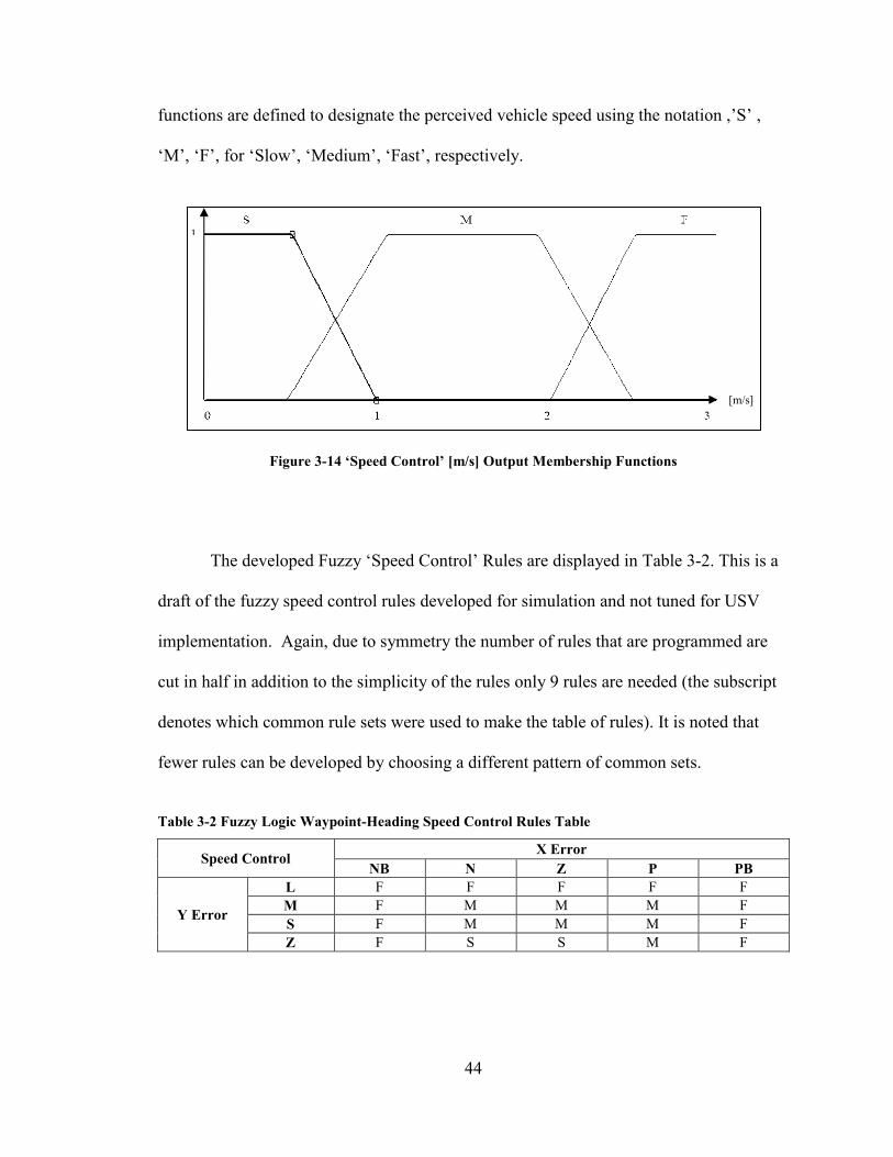
3.3.2 Waypoint-Heading Guidance Controller Simulation Testing ..................... 45
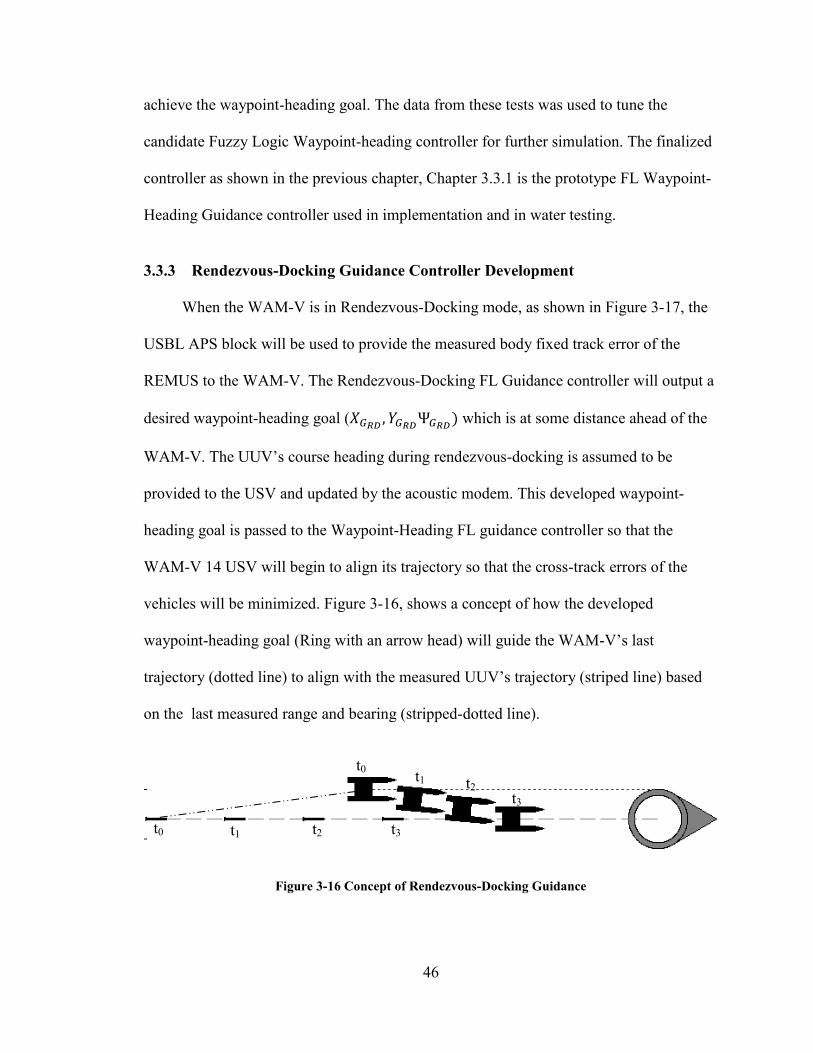
3.3.3 Rendezvous-Docking Guidance Controller Development.......................... 46
3.3.4 Rendezvous-Docking Guidance Controller Simulation Testing................. 54
3.4 High-Level Guidance System Implementation & Experimentation .................. 56
3.4.1 High-Level Autonomous Launch & Recovery Mission Architecture ........ 56
3.4.2 High-Level Guidance System Architecture, Communication
Implementation ........................................................................................... 59
3.5 High-level Controller Experiment ...................................................................... 64
3.5.1 Experimental Operation, WAM-V 14 USV ALR platform ........................ 64
3.5.2 Testing Location ......................................................................................... 66
3.5.3 Testing Procedure, Fuzzy Logic Waypoint-Heading Guidance Controller 67
4. Results ....................................................................................................................... 70
4.1 Simulations ......................................................................................................... 70
4.1.1 Waypoint-Heading Guidance Controller .................................................... 70
Page 10
x
4.1.2 Rendezvous-Docking Guidance Controller ................................................ 73
4.2 In-water Testing, Waypoint-Heading Guidance Controller ............................... 76
4.2.1 Adaptive Back-Stepping Low-Level Controller, High-Level Waypoint-
Heading Fuzzy Logic Guidance Controller Tests ...................................... 77
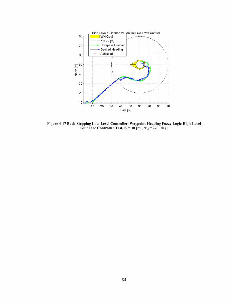
4.2.2 Back-Stepping Low-Level Controller, High-Level Waypoint-Heading
Fuzzy Logic Guidance Controller Tests ..................................................... 81
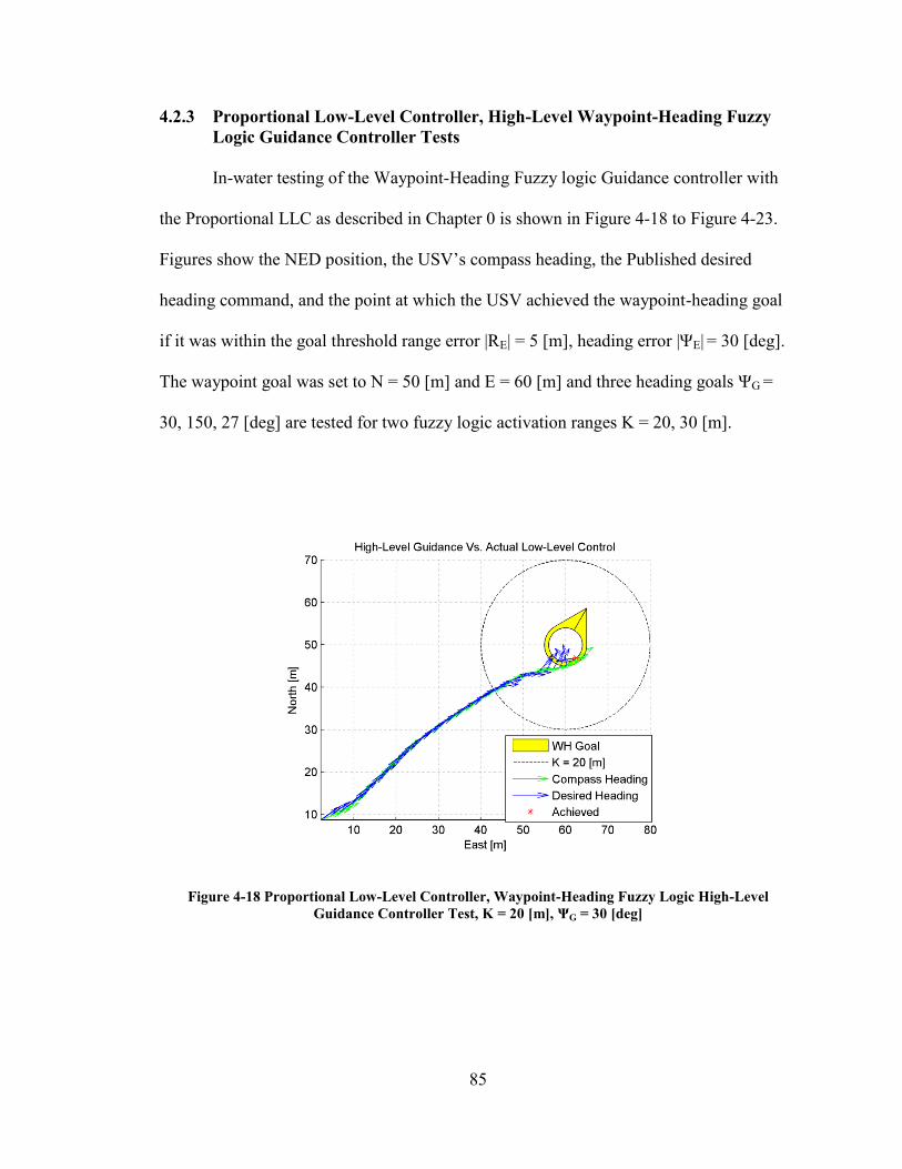
4.2.3 Proportional Low-Level Controller, High-Level Waypoint-Heading Fuzzy
Logic Guidance Controller Tests ............................................................... 85
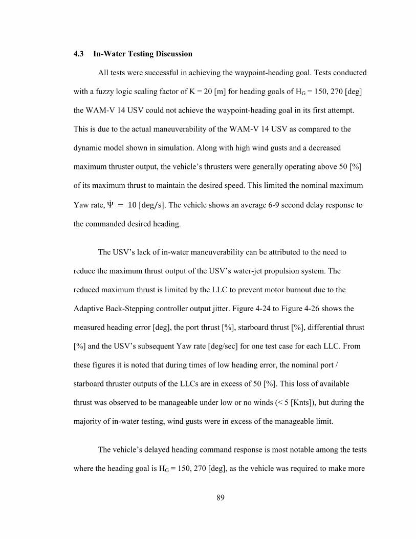
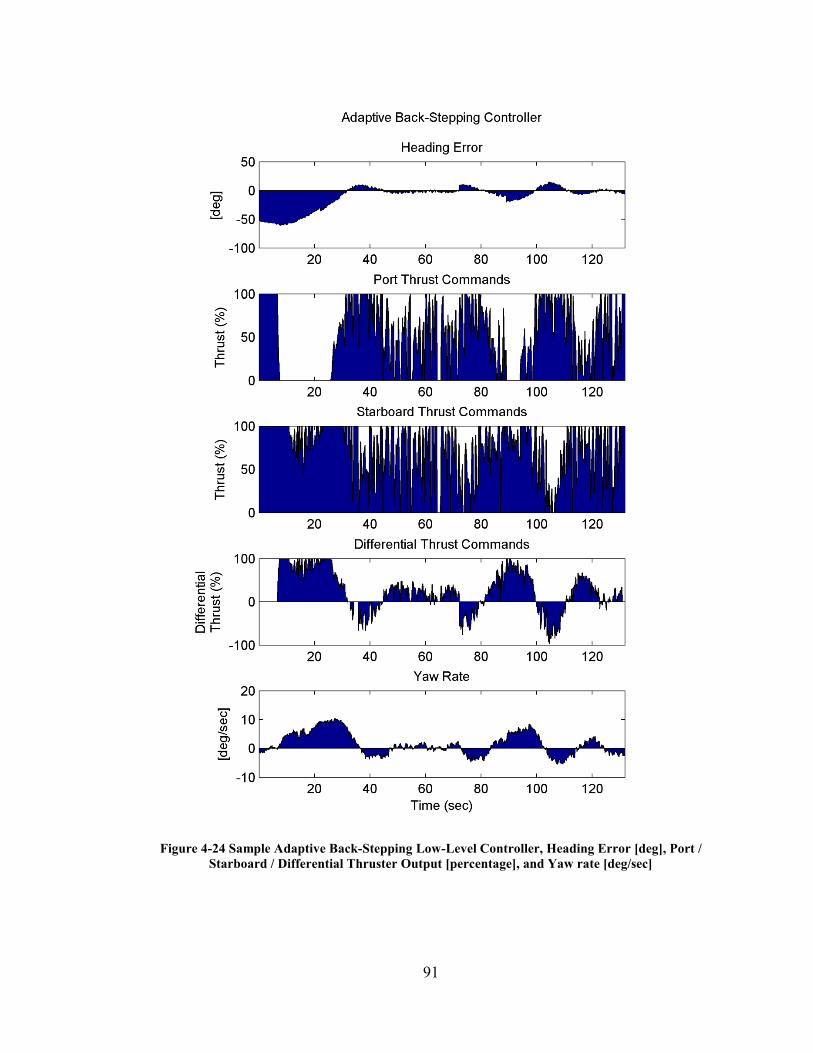
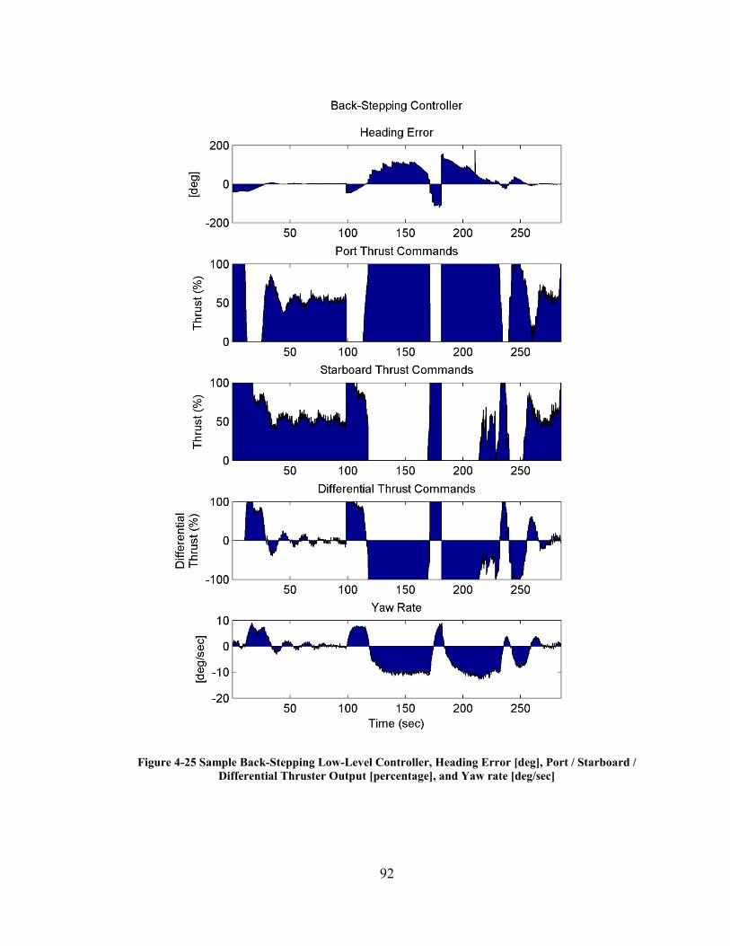
4.3 In-Water Testing Discussion .............................................................................. 89
5. Conclusions & Future Work ...................................................................................... 96
5.1 Conclusions ........................................................................................................ 96
5.2 Future Work ....................................................................................................... 99
6. Appendix ................................................................................................................. 100
A. Fuzzy Logic Example....................................................................................... 100
B. WAM-V 14 USV Model .................................................................................. 106
7. References ............................................................................................................... 110
Page 11
xi
List of Tables
Table 1-1 DoD Unmanned Maritime Systems Development Timeline [3] ........................ 4
Table 1-2 Principal characteristics of the WAM-V 14 USV [15] ...................................... 6
Table 1-3 REMUS 100 UUV specifications [23] ............................................................. 13
Table 3-1 Fuzzy Logic Waypoint-Heading Heading Control Rules Table ...................... 41
Table 3-2 Fuzzy Logic Waypoint-Heading Speed Control Rules Table .......................... 44
Table 3-3 Fuzzy Logic Rendezvous-Docking Controller, 'Y' output Rules ..................... 52
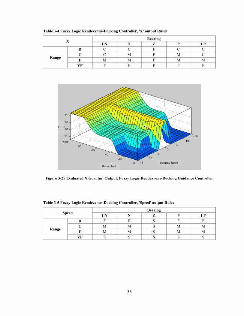
Table 3-4 Fuzzy Logic Rendezvous-Docking Controller, 'X' output Rules ..................... 53
Table 3-5 Fuzzy Logic Rendezvous-Docking Controller, 'Speed' output Rules .............. 53
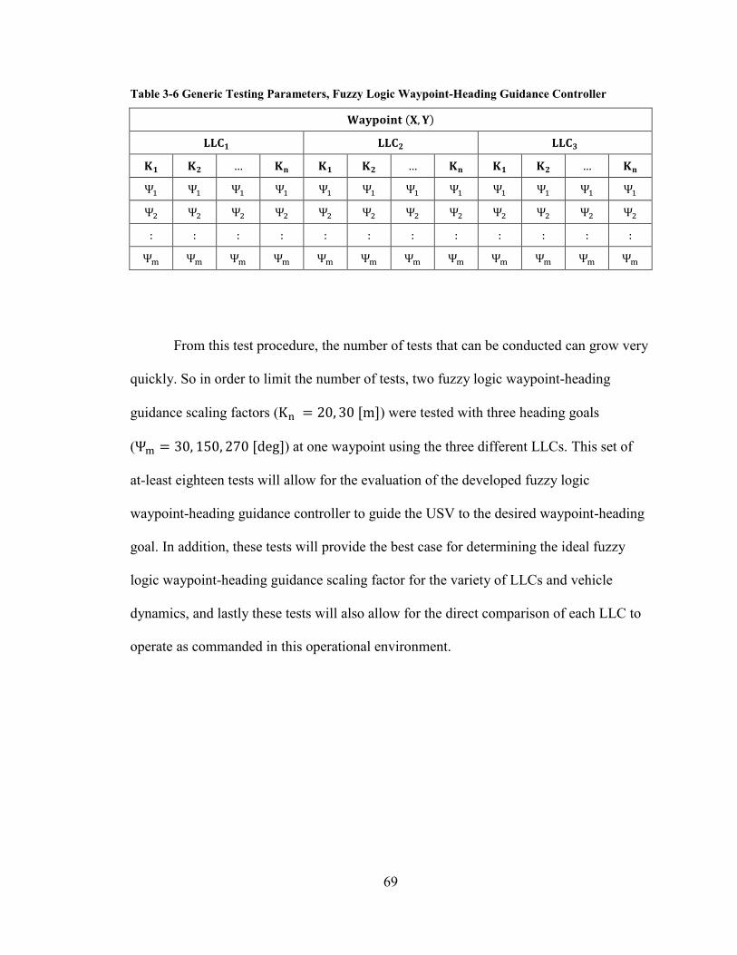
Table 3-6 Generic Testing Parameters, Fuzzy Logic Waypoint-Heading Guidance
Controller .......................................................................................................... 69
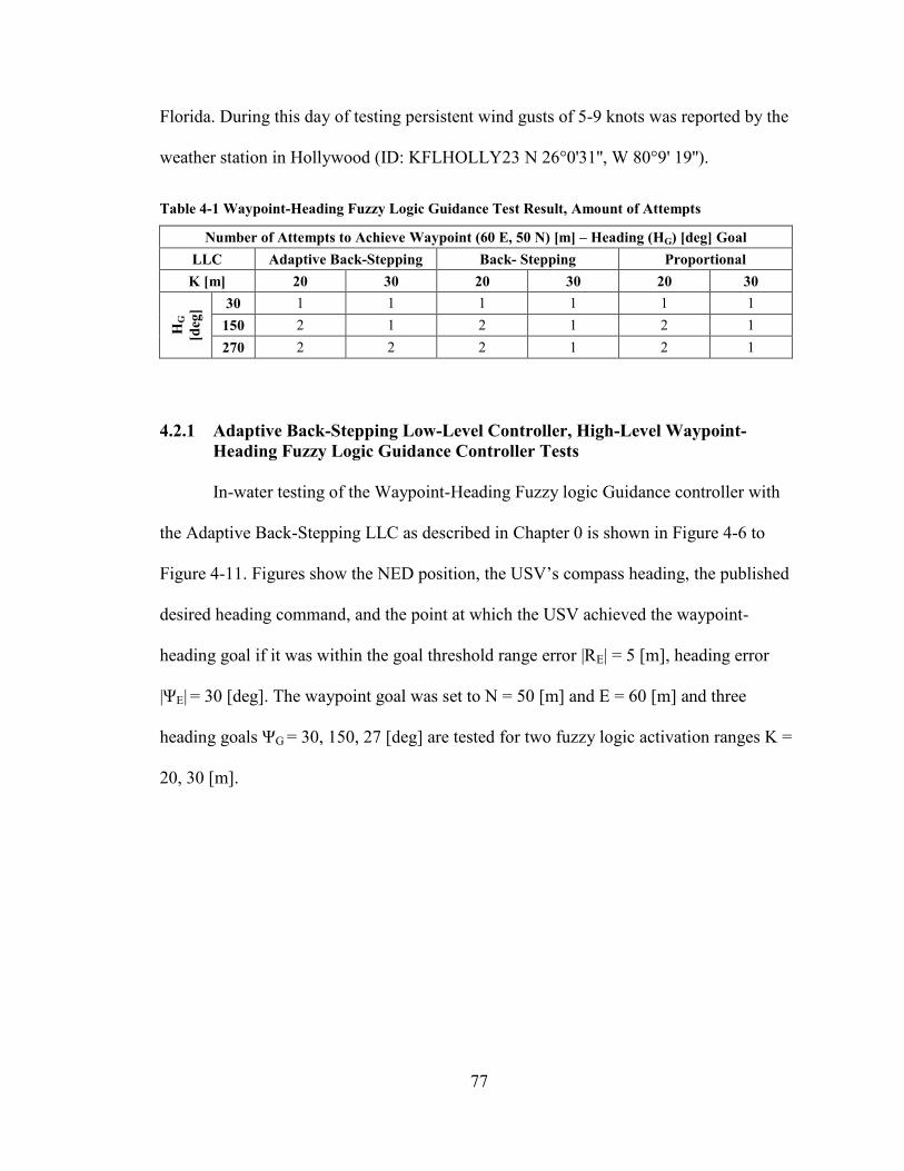
Table 4-1 Waypoint-Heading Fuzzy Logic Guidance Test Result, Amount of Attempts 77
Table 4-2 System Architecture Performance, Sample ...................................................... 94
Table 2-1 WAM-V 14 Hydrodynamic Coefficients ....................................................... 108
Page 12
xii
List of Figures
Figure 1-1 WAM-V 14 USV ALR Platform ...................................................................... 6
Figure 1-2 WAM-V 14 USV Navigation Communication & Control Box, Guidance and
Supervisory RC Control Diagram ..................................................................... 8
Figure 1-3 REMUS 100 UUV .......................................................................................... 12
Figure 2-1 Line of Sight Guidance ................................................................................... 20
Figure 2-2 K-R Potential Field Navigation [9] ................................................................. 21
Figure 2-3 Sample Cross Track (X Error) FUZZY Membership Functions, Fuzzy Logic
Waypoint-Heading Guidance Control ............................................................ 23
Figure 2-4 Localized Goal Coordinate Transform & Localized Fuzzy Docking Map [4] 25
Figure 2-5 Fuzzy Waypoint Guidance Diagram [40] ....................................................... 26
Figure 2-6 Fuzzy Rules Map for UUV Docking to a Moving Submarine [11] ................ 27
Figure 3-1 ALR Concept of Operations Flow Block Diagram ......................................... 32
Figure 3-2 System Simulation for ALR Mission Scenario, Simulink Block Diagram ..... 33
Figure 3-3 WAM-V Model & Low-Level Control Block ................................................ 34
Figure 3-4 INS/GPS Mocked Sensor Model with Noise .................................................. 35
Figure 3-5 GPS/INS Stationary Measurements of 1000 Samples .................................... 35
Figure 3-6 Simulink model of High-level Guidance Controller ....................................... 36
Figure 3-7 Waypoint-Heading Fuzzy Logic Guidance Architecture ................................ 37
Figure 3-8 Waypoint-Heading Goal Centric/Fixed Error Coordinate Transform ............ 38
Figure 3-10 Normalized ‘xError’ [m/m] Input Membership Functions ........................... 39
Page 13
xiii
Figure 3-11 Normalized Symetrical ‘yError’ [|m/m|] Input Membership Functions ....... 40
Figure 3-12 Heading Control [deg] Output Membership Functions ................................ 41
Figure 3-13 Goal-Centric Heading Output, Fuzzy Logic Waypoint-Heading Guidance
Controller, Tuned for WAM-V 14 USV Simulation ..................................... 42
Figure 3-14 Goal-Centric Heading Output, Fuzzy Logic Waypoint-Heading Guidance
Controller, Tuned for WAM-V 14 USV Implementation ............................. 43
Figure 3-15 ‘Speed Control’ [m/s] Output Membership Functions ................................. 44
Figure 3-16 Waypoint-Heading Fuzzy Logic Guidance, Desired Speed Output [m/s] .... 45
Figure 3-17 Concept of Rendezvous-Docking Guidance ................................................. 46
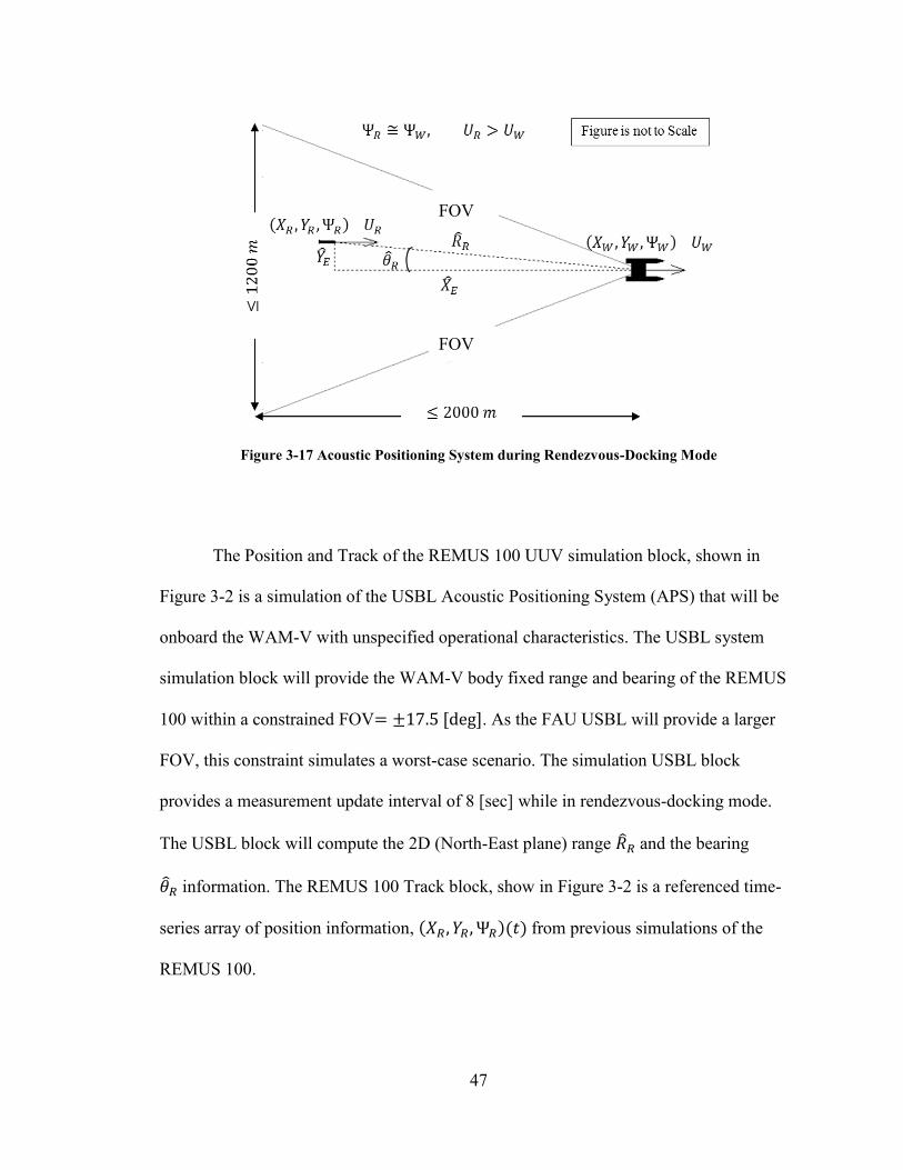
Figure 3-18 Acoustic Positioning System during Rendezvous-Docking Mode ............... 47
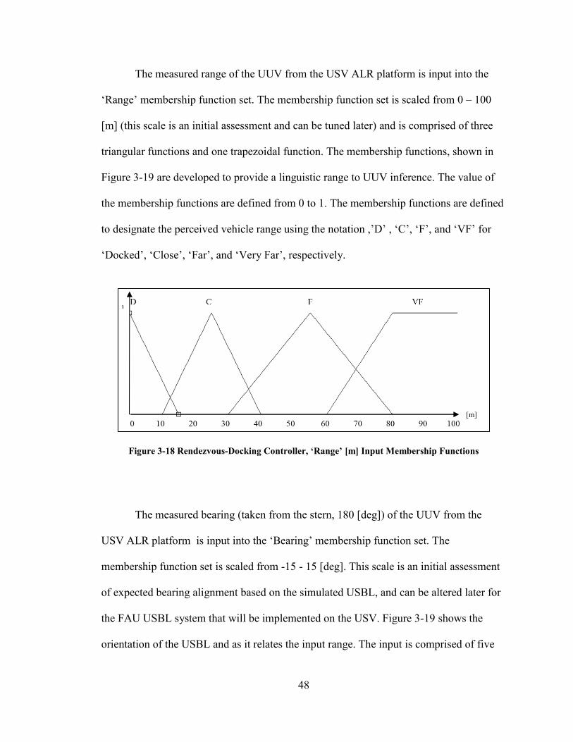
Figure 3-19 Rendezvous-Docking Controller, ‘Range’ [m] Input Membership Functions
....................................................................................................................... 48
Figure 3-20 WAM-V 14 USV ALR Platform, USBL Bearing Measurement
Configuration ................................................................................................. 49
Figure 3-21 Rendezvous-Docking Controller, 'Bearing' [deg] Input Membership
Functions ....................................................................................................... 49
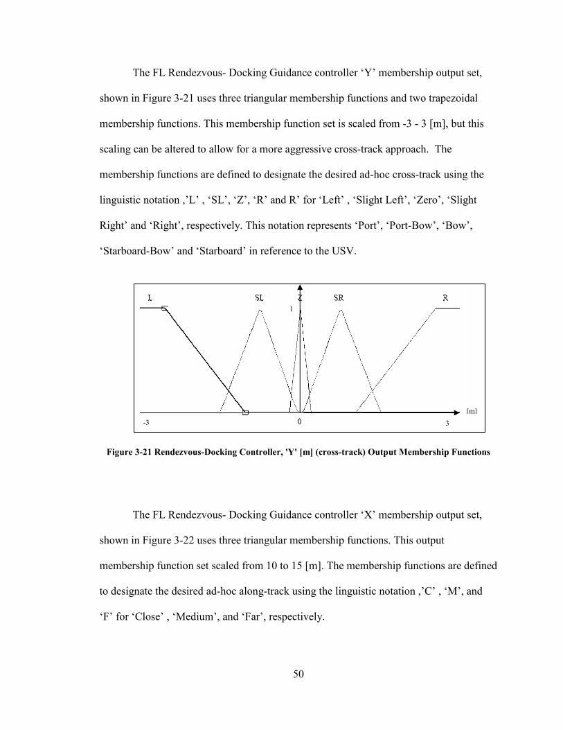
Figure 3-22 Rendezvous-Docking Controller, 'Y' [m] (cross-track) Output Membership
Functions ....................................................................................................... 50
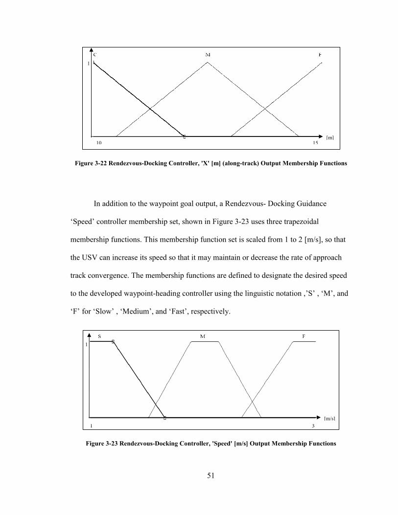
Figure 3-23 Rendezvous-Docking Controller, 'X' [m] (along-track) Output Membership
Functions ....................................................................................................... 51
Figure 3-24 Rendezvous-Docking Controller, 'Speed' [m/s] Output Membership
Functions ....................................................................................................... 51
Page 14
xiv
Figure 3-25 Evaluated Y Goal [m] Output, Fuzzy Logic Rendezvous-Docking Guidance
Controller ....................................................................................................... 52
Figure 3-26 Evaluated X Goal [m] Output, Fuzzy Logic Rendezvous-Docking Guidance
Controller ....................................................................................................... 53
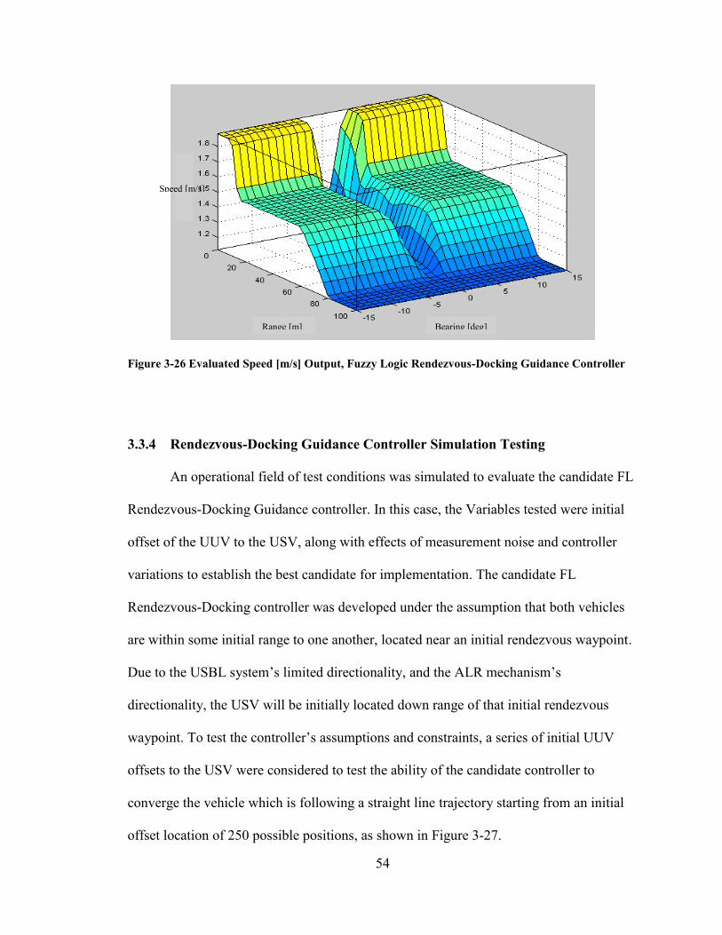
Figure 3-27 Evaluated Speed [m/s] Output, Fuzzy Logic Rendezvous-Docking Guidance
Controller ....................................................................................................... 54
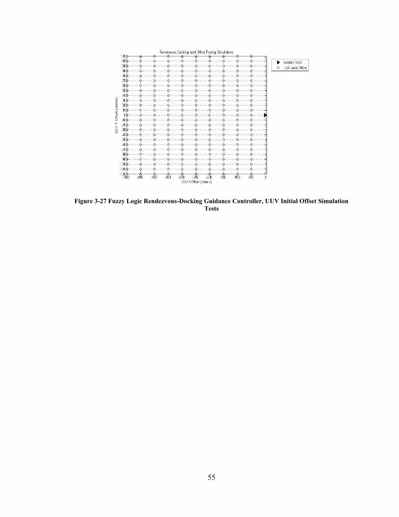
Figure 3-28 Fuzzy Logic Rendezvous-Docking Guidance Controller, UUV Initial Offset
Simulation Tests ............................................................................................ 55
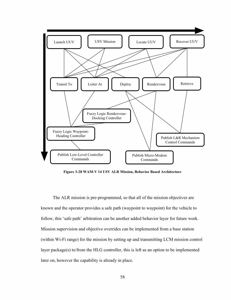
Figure 3-29 WAM-V 14 USV ALR Mission, Behavior Based Architecture ................... 58
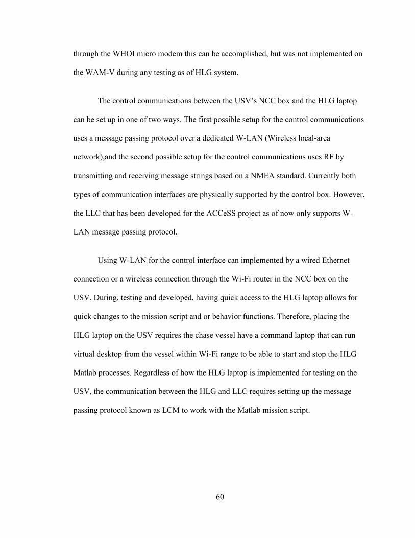
Figure 3-30 Communication interfaces between the High-Level Guidance laptop, the
UUV and, the USV’s NCC box ..................................................................... 61
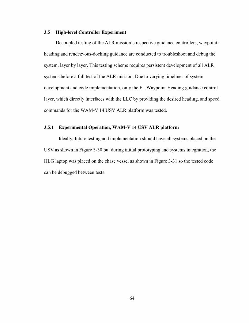
Figure 3-31 USV Experiment Operational Setup, HLG system onboard USV with
Mission Control and Telemetry CPU on Chase vessel ................................. 65
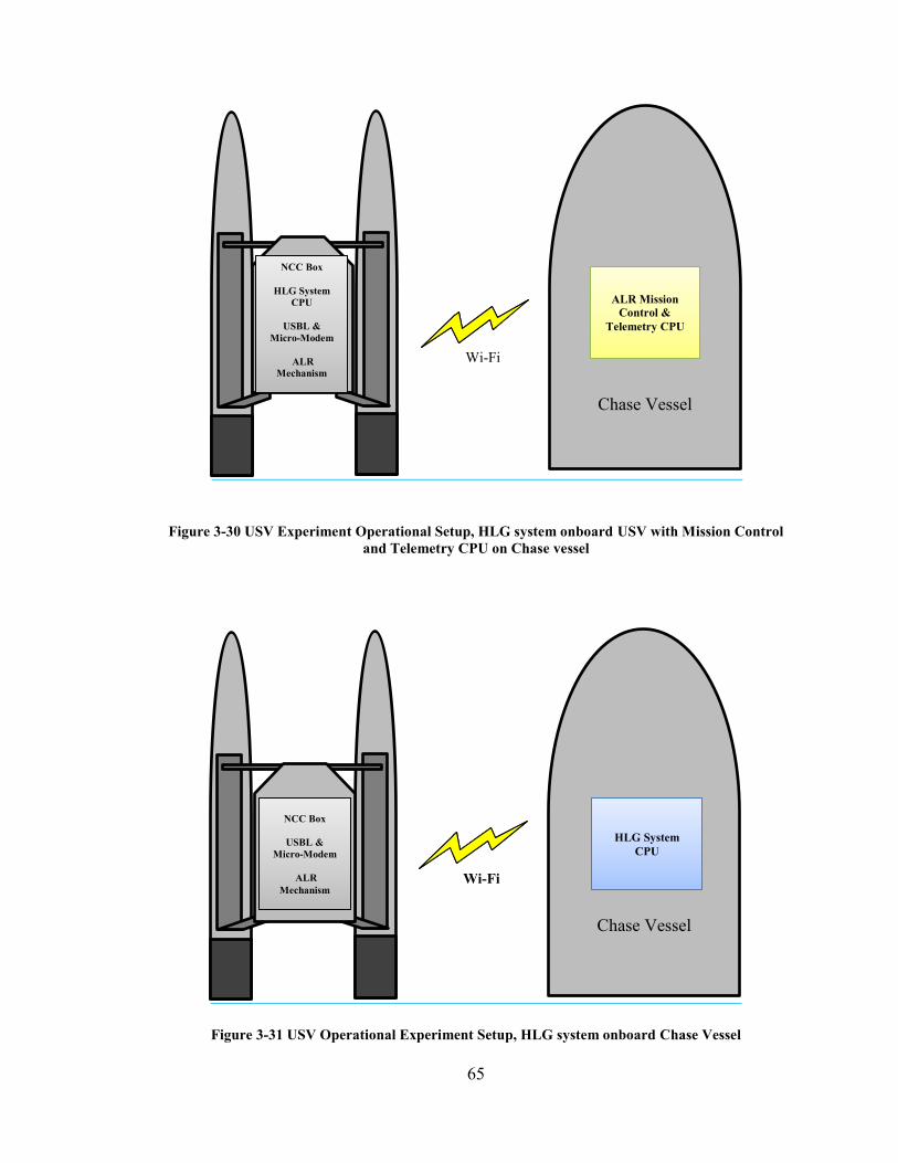
Figure 3-32 USV Operational Experiment Setup, HLG system onboard Chase Vessel .. 65
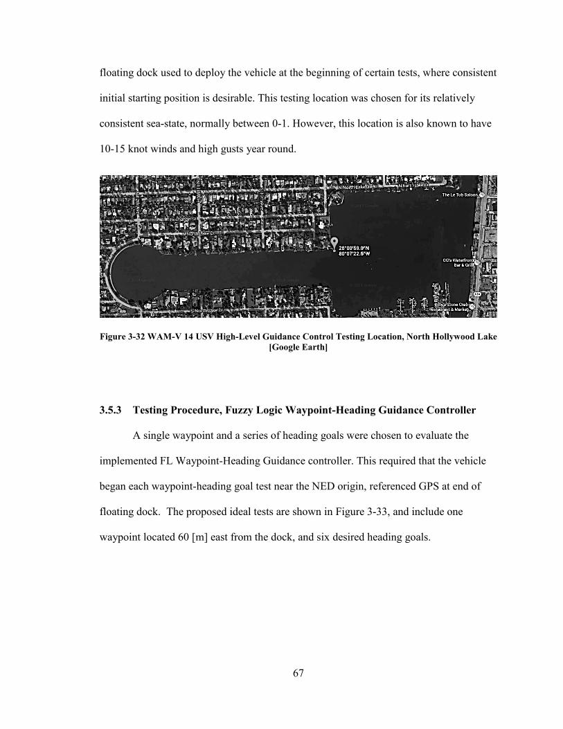
Figure 3-33 WAM-V 14 USV High-Level Guidance Control Testing Location, North
Hollywood Lake [Google Earth] ................................................................... 67
Figure 3-34 Proposed Ideal Tests of the Fuzzy Logic Waypoint-Heading Guidance
Controller, (Blue line: Lake boundary, Green Line: Start-to-Goal Vector,
Black Arrows: Goal headings). ..................................................................... 68
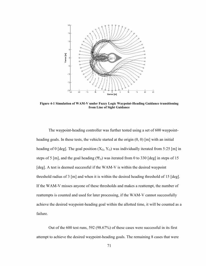
Figure 4-1 Simulation of WAM-V under Fuzzy Logic Waypoint-Heading Guidance
transitioning from Line of Sight Guidance ..................................................... 71
Figure 4-2 Waypoint-Heading Fuzzy Logic Guidance Controller Simulations, Figures are
a subset of the 600 cases tested ....................................................................... 72
Page 15
xv
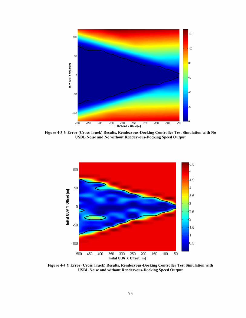
Figure 4-3 Y Error (Cross Track) Results, Rendezvous-Docking Controller Test
Simulation with No USBL Noise and No without Rendezvous-Docking Speed
Output ............................................................................................................. 75
Figure 4-4 Y Error (Cross Track) Results, Rendezvous-Docking Controller Test
Simulation with USBL Noise and without Rendezvous-Docking Speed Output
......................................................................................................................... 75
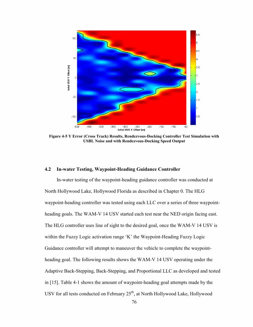
Figure 4-5 Y Error (Cross Track) Results, Rendezvous-Docking Controller Test
Simulation with USBL Noise and with Rendezvous-Docking Speed Output 76
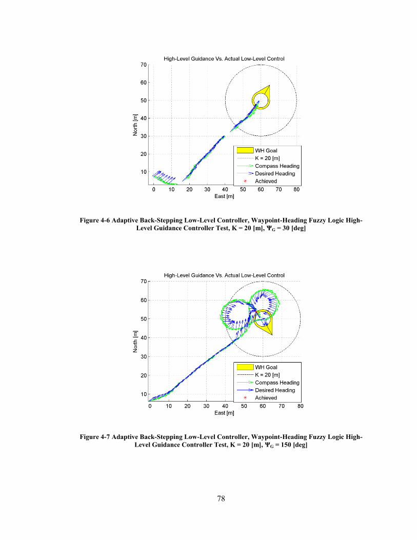
Figure 4-6 Adaptive Back-Stepping Low-Level Controller, Waypoint-Heading Fuzzy
Logic High-Level Guidance Controller Test, K = 20 [m], ΨG = 30 [deg] ...... 78
Figure 4-7 Adaptive Back-Stepping Low-Level Controller, Waypoint-Heading Fuzzy
Logic High-Level Guidance Controller Test, K = 20 [m], ΨG = 150 [deg] .... 78
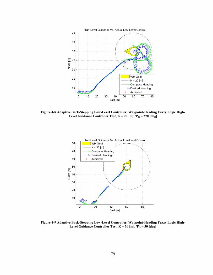
Figure 4-8 Adaptive Back-Stepping Low-Level Controller, Waypoint-Heading Fuzzy
Logic High-Level Guidance Controller Test, K = 20 [m], ΨG = 270 [deg] .... 79
Figure 4-9 Adaptive Back-Stepping Low-Level Controller, Waypoint-Heading Fuzzy
Logic High-Level Guidance Controller Test, K = 30 [m], ΨG = 30 [deg] ...... 79
Figure 4-10 Adaptive Back-Stepping Low-Level Controller, Waypoint-Heading Fuzzy
Logic High-Level Guidance Controller Test, K = 30 [m], ΨG = 150 [deg] .. 80
Figure 4-11 Adaptive Back-Stepping Low-Level Controller, Waypoint-Heading Fuzzy
Logic High-Level Guidance Controller Test, K = 30 [m], ΨG = 270 [deg] .. 80
Figure 4-12 Back-Stepping Low-Level Controller, Waypoint-Heading Fuzzy Logic High-
Level Guidance Controller Test, K = 20 [m], ΨG = 30 [deg] ........................ 81
Page 16
xvi
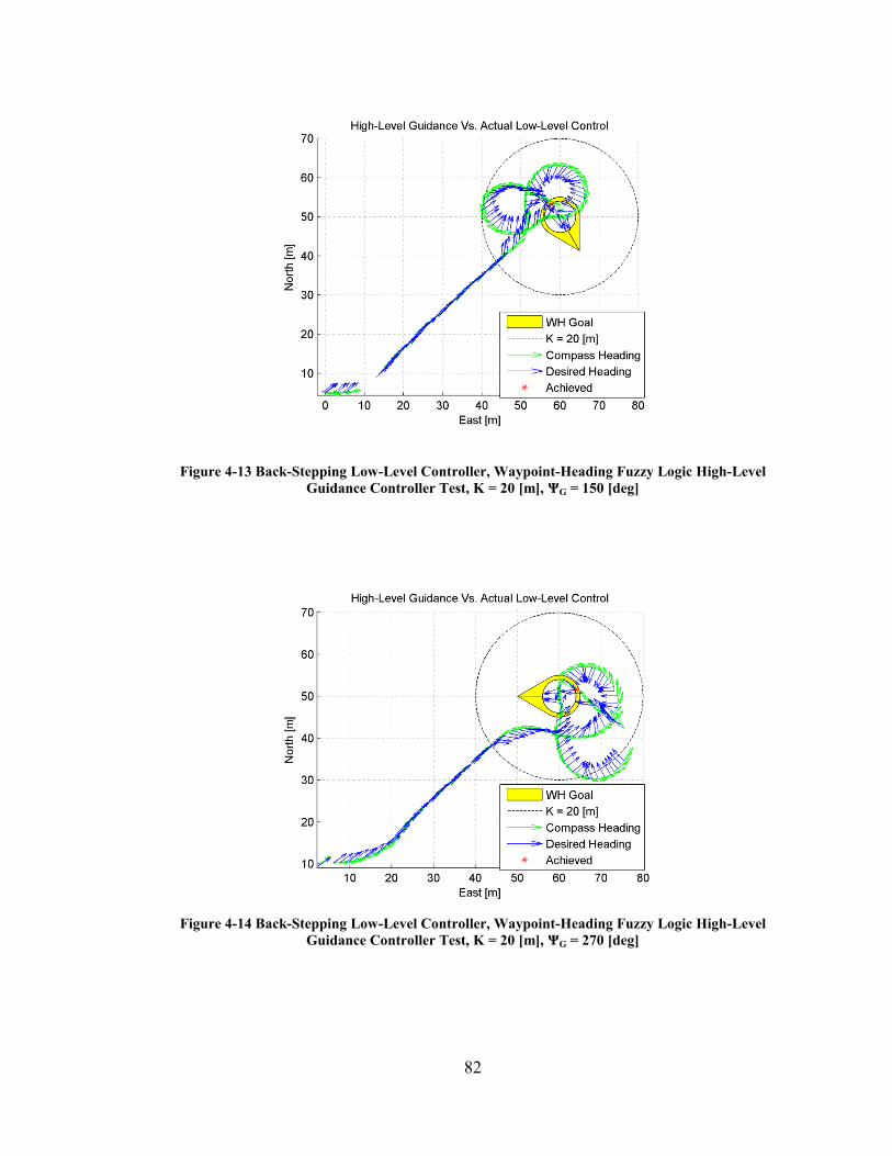
Figure 4-13 Back-Stepping Low-Level Controller, Waypoint-Heading Fuzzy Logic High-
Level Guidance Controller Test, K = 20 [m], ΨG = 150 [deg] ...................... 82
Figure 4-14 Back-Stepping Low-Level Controller, Waypoint-Heading Fuzzy Logic High-
Level Guidance Controller Test, K = 20 [m], ΨG = 270 [deg] ...................... 82
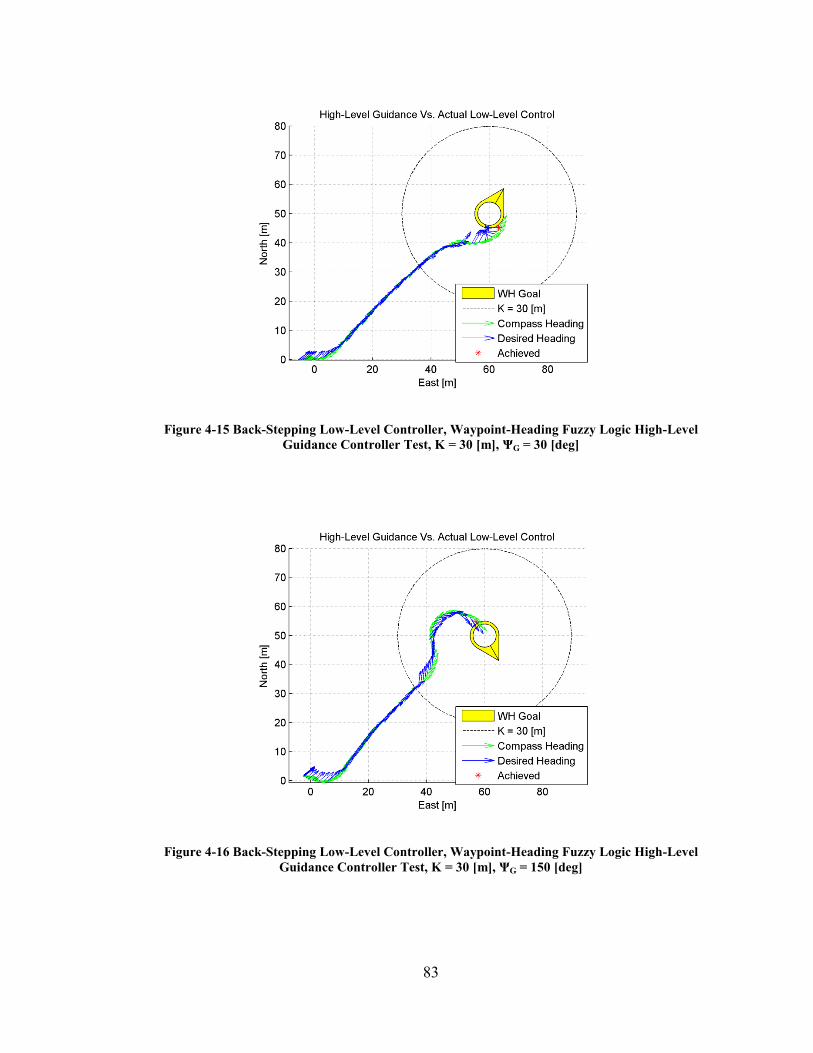
Figure 4-15 Back-Stepping Low-Level Controller, Waypoint-Heading Fuzzy Logic High-
Level Guidance Controller Test, K = 30 [m], ΨG = 30 [deg] ........................ 83
Figure 4-16 Back-Stepping Low-Level Controller, Waypoint-Heading Fuzzy Logic High-
Level Guidance Controller Test, K = 30 [m], ΨG = 150 [deg] ...................... 83
Figure 4-17 Back-Stepping Low-Level Controller, Waypoint-Heading Fuzzy Logic High-
Level Guidance Controller Test, K = 30 [m], ΨG = 270 [deg] ...................... 84
Figure 4-18 Proportional Low-Level Controller, Waypoint-Heading Fuzzy Logic High-
Level Guidance Controller Test, K = 20 [m], ΨG = 30 [deg] ........................ 85
Figure 4-19 Proportional Low-Level Controller, Waypoint-Heading Fuzzy Logic High-
Level Guidance Controller Test, K = 20 [m], ΨG = 150 [deg] ...................... 86
Figure 4-20 Proportional Low-Level Controller, Waypoint-Heading Fuzzy Logic High-
Level Guidance Controller Test, K = 20 [m], ΨG = 270 [deg] ...................... 86
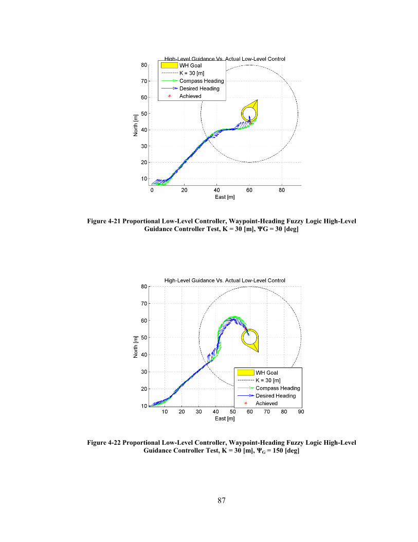
Figure 4-21 Proportional Low-Level Controller, Waypoint-Heading Fuzzy Logic High-
Level Guidance Controller Test, K = 30 [m], ΨG = 30 [deg] ....................... 87
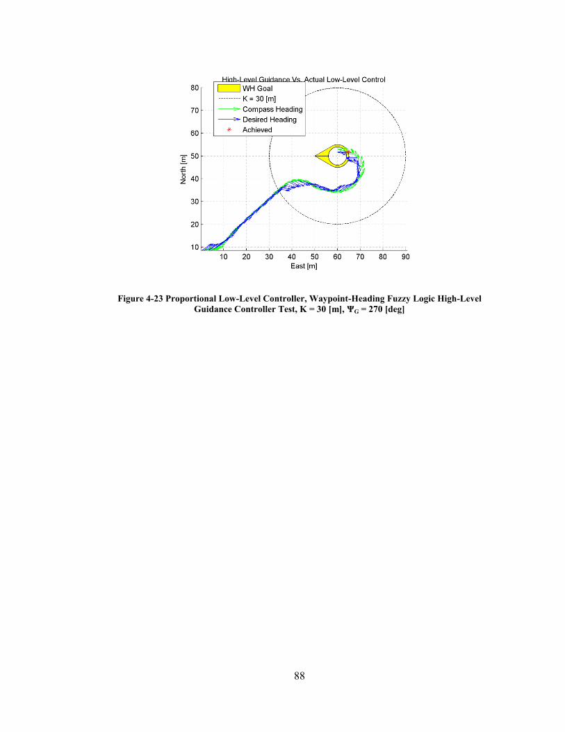
Figure 4-22 Proportional Low-Level Controller, Waypoint-Heading Fuzzy Logic High-
Level Guidance Controller Test, K = 30 [m], ΨG = 150 [deg] ...................... 87
Figure 4-23 Proportional Low-Level Controller, Waypoint-Heading Fuzzy Logic High-
Level Guidance Controller Test, K = 30 [m], ΨG = 270 [deg] ...................... 88
Page 17
xvii
Figure 4-24 Sample Adaptive Back-Stepping Low-Level Controller, Heading Error [deg],
Port / Starboard / Differential Thruster Output [percentage], and Yaw rate
[deg/sec] ........................................................................................................ 91
Figure 4-25 Sample Back-Stepping Low-Level Controller, Heading Error [deg], Port /
Starboard / Differential Thruster Output [percentage], and Yaw rate [deg/sec]
....................................................................................................................... 92
Figure 4-26 Sample Proportional Low-Level Controller, Heading Error [deg], Port /
Starboard / Differential Thruster Output [percentage], and Yaw rate [deg/sec]
....................................................................................................................... 93
Figure 4-27 Sample Test Control Loop Rate, Comparison .............................................. 95
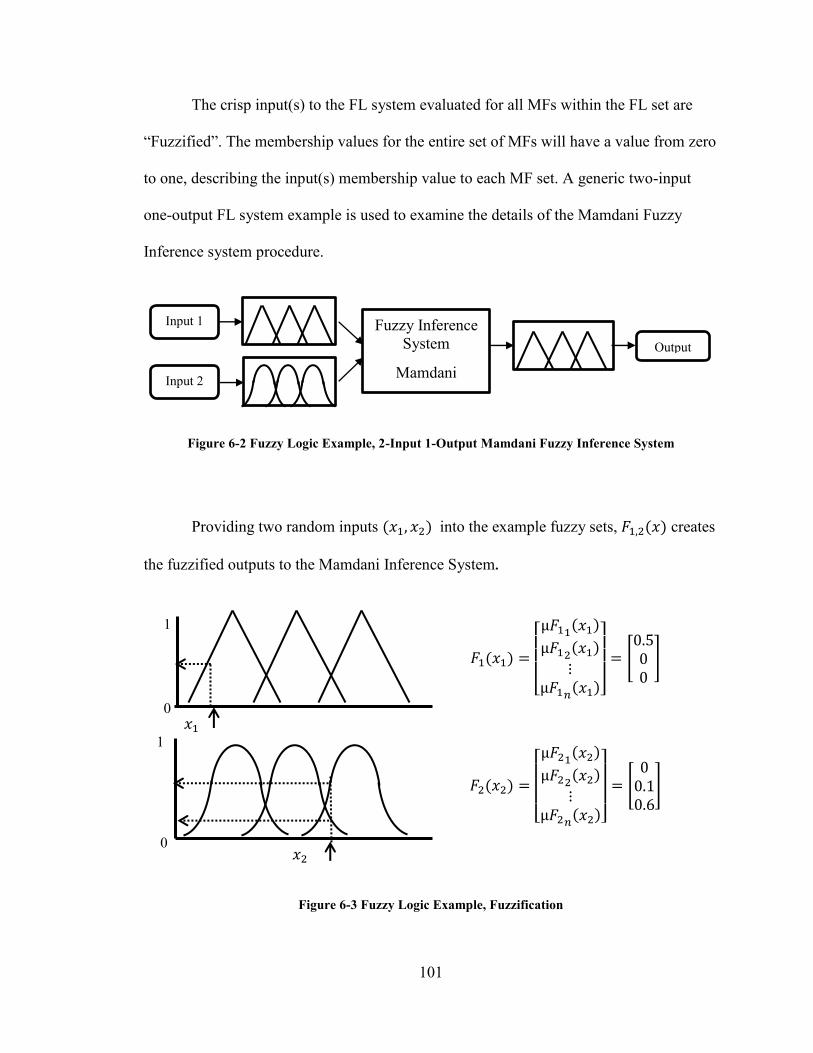
Figure 6-1 Fuzzy Logic Membership Functions ............................................................. 100
Figure 6-2 Fuzzy Logic Example, 2-Input 1-Output Mamdani Fuzzy Inference System
....................................................................................................................... 101
Figure 6-3 Fuzzy Logic Example, Fuzzification ............................................................ 101
Figure 6-4 Fuzzy Inference Process ................................................................................ 102
Figure 6-5 Fuzzy Inference Computation, Rule #1 ........................................................ 103
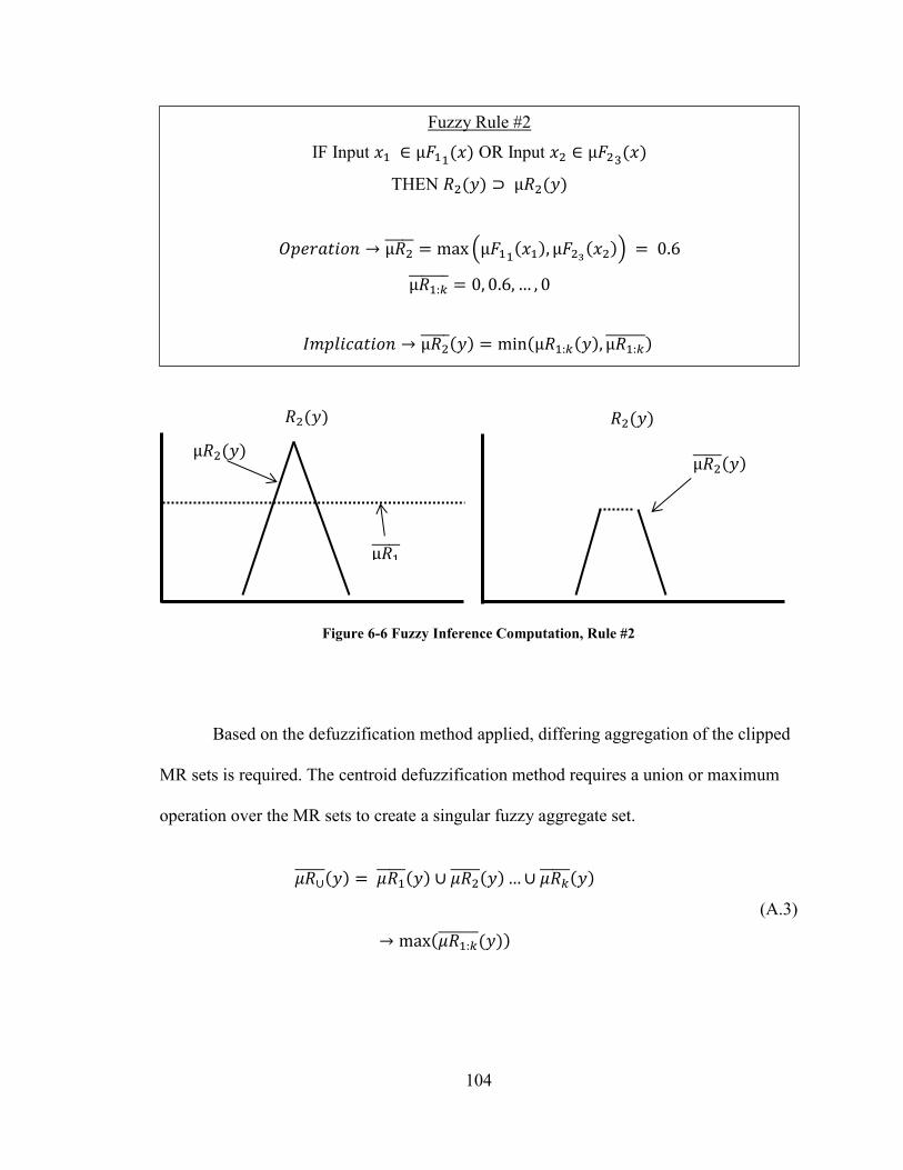
Figure 6-6 Fuzzy Inference Computation, Rule #2 ........................................................ 104
Figure 6-7 Fuzzy Membership Relation Aggregation .................................................... 105
Figure 6-8 Fuzzy Logic Defuzzification, Centroid Method ........................................... 105
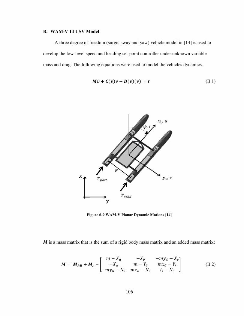
Figure 6-9 WAM-V Planar Dynamic Motions [14] ....................................................... 106
Page 18
xviii
Nomenclature & Acronyms
ACOMMS: Acoustic Communication Systems.
ALR: Autonomous Launch and Recovery.
APS: Acoustic Positioning System.
CEP: Circular Error Probability.
COLREGS: Collision Regulations.
FAU: Florida Atlantic University.
FL: Fuzzy Logic.
GNCC: Guidance, Navigation, Communication and Control.
GPS: Global Positioning System.
HLG: High-Level Guidance.
H-UMS: Heterogeneous Unmanned Maritime System.
IMU: Inertial Measurement Unit.
INS: Internal Navigation System.
L&R: Launch & Recovery.
Page 19
xix
LBL: Long Base Line.
LCM: Lightweight Communication and Marshaling.
LLC: Low-Level Controller.
LOS: Line of Sight.
MAR: Marine Advanced Research.
MCM: Mine Counter Measures.
MF: Membership Function.
MR: Membership Relation.
NCC: Navigation, Communications and Control.
PWM: Pulse Width Modulation.
RC: Radio Control.
REMUS: Remote Environmental Monitoring UnitS.
RF: Radio Frequency.
SBC: Single-Board Computer.
UMV: Unmanned Marine Vehicles.
USBL: Ultra Short Base Line. ; Ultra Short Baseline.
USV: Unmanned Surface Vehicle.
Page 20
xx
UUV: Unmanned Underwater Vehicle.
WAM-V: Wave Adaptive Modular Vehicle.
W-LAN: Wireless-Local Area Network.
Page 21
1
1. Introduction
The objective of this thesis is to research and develop a High-Level Guidance
(HLG) controller for an Unmanned Surface Vehicle (USV) tasked to perform an
Autonomous Launch and Recovery (ALR) mission of an Unmanned Underwater Vehicle
(UUV). The Wave Adaptive Modular Vehicle (WAM-V) 14 USV (Mother Vehicle), and
the Remote Environmental Monitoring UnitS (REMUS) 100 UUV (Daughter Vehicle),
are the Unmanned Marine Vehicles (UMV) chosen for the development and
implementation of an ALR mission. The development of the Heterogeneous Unmanned
Maritime System (H-UMS) must address the issues of guidance, navigation and relative
positioning (Mother to Daughter and vice versa), communications, control and Launch &
Recovery (L&R) mechanism for an ALR mission. The REMUS 100 UUV is outfitted
with the necessary guidance, navigation, communications and control to execute a
hydrographic survey and dock to a moving source provided an initial course alignment.
Navigation, Communications and Control (NCC) of the WAM-V 14 USV has been
developed and successfully operated with various Low-Level Controller (LLC) schemes.
An Acoustic Positioning System (APS) is provided by, an Ultra Short Base Line (USBL)
to track the relative position of the UUV from the USV. The L&R mechanism for the
WAM-V 14 USV ALR platform is under development at FAU. Therefore, a HLG
controller is the last area of development needed to complete the WAM-V 14 USV ALR
platform, thus providing the motivation of this thesis work.
Page 22
2
1.1 Background
The emerging market in maritime autonomous systems of UMVs such as UUV
and USV systems used in collaboration for search and survey missions provide robust
mission awareness and improve overall operations for Oil & Gas, Scientific research and
Defense [1] [2] [3]. Resident UUV systems (UUVs that operate continuously underwater
for an extended period) are vital to persistent survey and maintenance of subsea surface
installations where the work can be long and dull. USV systems have a key role in the
future development of resident UUV operations as well as an immediate need for defense
and scientific research [1]. A rapidly deployable mobile ALR platform that can be sent to
deploy a UUV system from one site of interest to the next, with little or no human
supervision all while providing support to the UUV for navigation and command and
control [2].
Examining the current state of UUV operations can provide some insight into the
problems facing the underwater search and survey community. These common problems
include, limited operation time and deployment reach for a single deployed UUV system.
This issue is based on the individual UUV onboard power system’s limitations (e.g.
battery or fuel cell) [1]. Many efforts are being made to reduce power consumption and
increase onboard power storage and density [2].
Conducting search and survey operations with an UUV for any amount of time
requires the operation be conducted under the supervision of a manned vessel. The costs
that are associated with conducting search and survey operations include crewmembers/
operator fatigue, risks to vessel and crew during adverse weather and the direct financial
costs for manned vessel operations, which can range from 20k to 50k [$/day] [2]. This is
Page 23
3
a primary reason why most search and survey operations are conducted by companies/
organizations involved with the petroleum industry, government and or defense.
The application of an ALR platform provides the capability to expand the current
limited use of small UUV operations. UUV operators in hazardous littoral zones such as
post disaster inspections of coastal areas, Mine Counter Measures (MCM), port security
and continuous or long endurance surveys are areas where implementing an ALR
platform can expand the uses of UUV systems [3]. This cross application need for ALR
platforms is creating opportunities for innovative industry solutions, advanced defense
systems and providing funding for academic research to keep up with the pace of need
for information about our oceans and waterways.
1.1.1 Autonomous Launch and Recovery Background
Challenges of implementing an USV ALR platform are in the design and
development of a capable surface vehicle, the L&R mechanism, and in the rendezvous/
docking guidance. These issues and the author’s opinion on developing a solution to them
are discussed in brief within the following paragraphs. This is discussed only to provide
the reader with enough understanding to the issues that are facing the maritime
autonomous system’s community with an implementing an ALR platform.
Docking of a UUV for recovery to a mobile platform is a hard challenge to
overcome, as most developed docking mechanisms and controllers that have been
published are developed for stationary recovery of an UUV to a moored docking station
on the seafloor as shown in [4] [5] [6] [7] [8]. The capability of mobile docking is shown
in [9] [10] [11] , but these mobile docking scenarios are simulated/ conducted from a
Page 24
4
manned vessel, e.g. research vessel, or submarine. In addition to docking of the UUV for
an ALR mission, there is also a need to be able to download data, recharge batteries,
program missions and redeploy the UUV. This requires extensive mechanical and
electrical engineering to build a durable and robust docking mechanism.
Guidance, Navigation, Communication and Control (GNCC) of any proposed
ALR USV platform is the upmost importance to its final implementation. Compliance to
Collision Regulations (COLREGS) and industry standards is a current issue and topic of
research a stated in [3] [12] [13]. None the less, an ALR platform deployed in any
maritime environment should have supervisory control and be able to autonomously
operate safely while transiting to a launch site, deploy its daughter vehicle UUV and
perform its surface mission (separate or collaborative) while the UUV is performing its
own subsurface mission. Then the USV should intercept and rendezvous with the UUV
so that a final mobile docking maneuver to recover the UUV can be attempted. This ALR
mission scenario falls under the UMS Desired Capabilities Near/Mid Term goals.
In the following section, the Wave Adaptive Modular Vehicle 14 will be introduced
as a proposed platform for an ALR mission to support a REMUS 100 UUV in remote
search and survey operations.
Table 1-1 DoD Unmanned Maritime Systems Development Timeline [3]
Goals 2013 – 2017 2018 – 2021 2022 – 2030+
Near Term Mid Term Far Term
UMS Projects
Improved Power,
Communications, and Sensor
Systems
Effective Autonomy Systems and Avoidance
Algorithms. Security Architectures
UMS Desired Capabilities
Autonomy for specialized
missions in localized areas.
Increase networked systems
Increased missions in
expanded geographical
areas
Autonomous missions
worldwide
Page 25
5
1.2 WAM-V 14 USV ALR Platform
1.2.1 WAM-V 14
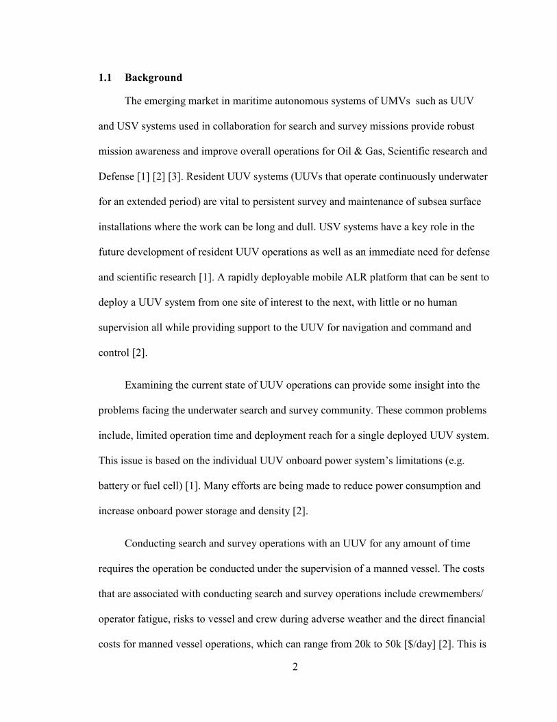
The WAM-V 14 USV is a 14 foot long inflatable pontoon hull style catamaran
vehicle designed by Marine Advanced Research (MAR), Inc. of Berkeley, CA. This
catamaran style vehicle allows for storage of a small UUV and a docking mechanism that
weighs less than the maximum rated payload capacity of ~114 kilograms (kg) in its
undercarriage for an ALR mission [14] [15]. The WAM-V 14 USV designed with front
independent pontoon suspension system that provides stability to the payload tray/
undercarriage, when the vehicle encounters small amplitude waves (sea state ≤ 2). This
makes the vehicle’s payload tray a suitable platform for an ALR mechanism.
The vehicle uses two cylindrical motor pods that house the propulsion systems’
batteries, motor controls and electric motor water-jets. The water-jet propulsion design
allows for safe interaction with UUVs and semi-submersed objects, such as debris and or
structures. The motor pods connected to the pontoons by a hinged connection and a
flexible connection to allow the motor pods to flex around the hinged joint so that the
motors remain submerged when encountering waves, providing persistence propulsion.
The independently controlled motor pods (Port and Starboard) provide propulsion for
forward velocity (Surge) and differential thrust for steering (Yaw) control. This
propulsion system is considered highly coupled and non-holonomic or under-actuated as
there are 3 degrees of freedom to consider for surface vehicles, namely Surge, Sway, and
Yaw. Figure 1-1 shows the WAM-V 14 USV ALR platform as used during testing.
The WAM-V 14 USV ALR platform has the following surface vehicle principal
characteristics, as found in [15] are displayed in Table 1-2. These principle characteristics
Page 26
6
are used in to develop the USV simulation model provided in [15] that is used in this
thesis work.
Figure 1-1 WAM-V 14 USV ALR Platform
Table 1-2 Principal characteristics of the WAM-V 14 USV [15]
Parameters Values
Length Overall (LOA) 4.29 [m]
Length on the Waterline (LWL) 3.21 [m]
Draft (aft and mid-length) 0.127 and 0.105 [m]
Beam Overall (BOA) 2.20 [m]
Beam on the Waterline (BWL) 2.19 [m]
Depth (keel to pontoon skid top) 0.39 [m]
Area of the Water-plane (AWP) 1.1 [m2]
Centerline-to-centerline Side Hull Separation (B) 1.83 [m]
Length to Beam Ratio (L/B) 2.34
Displacement (∇) 0.34 [m3]
Weight (W) 150 [kg]
Longitudinal Center of Gravity (LCG) 1.27 [m]
Page 27
7
1.2.2 Navigation, Communication & Control
For this project, the WAM-V 14 platform comes equipped with a Navigation
Communications and Control (NCC) box, shown in Figure 1-1, developed in house at
Florida Atlantic University. This system is housed in a plastic water resistant box and
contains a TS-78000 Single-Board Computer (SBC), an Ocean Server OS5000 digital
compass, Garmin Global Positioning System (GPS) that is aided with a XSENS MTi-G
Internal Navigation System (INS) for higher precision navigation, Radio Frequency (RF)
modem, Radio Control (RC) receiver, and a Wireless-Local Area Network (W-LAN)
[15] [16].
The framework of the NCC and Guidance software communications architecture
based upon the Lightweight Communication and Marshaling (LCM) Protocol. The LCM
communications protocol designed, uses UDP multicast for a low-latency decentralized
publish/subscribe message-passing scheme [17]. Targeted for use in real-time systems,
LCM allows for message passing between separate processes and code languages through
type specific bindings. Supported LCM code language bindings include C, C++, C#,
Java, Lua, Python, and MATLAB [18].
LCM allows the sensor drivers, state estimator, LLC and HLG controller to run
their own individual processes and then publish/subscribe to the navigational sensor data,
and guidance commands at their own desired rate, provided the processes are connected
to the W-LAN and the data types that are being published are known. LCM also allows
the process to buffer incoming subscribed messages. For more information on LCM and
its own internal systems, refer to [18].
Page 28
8
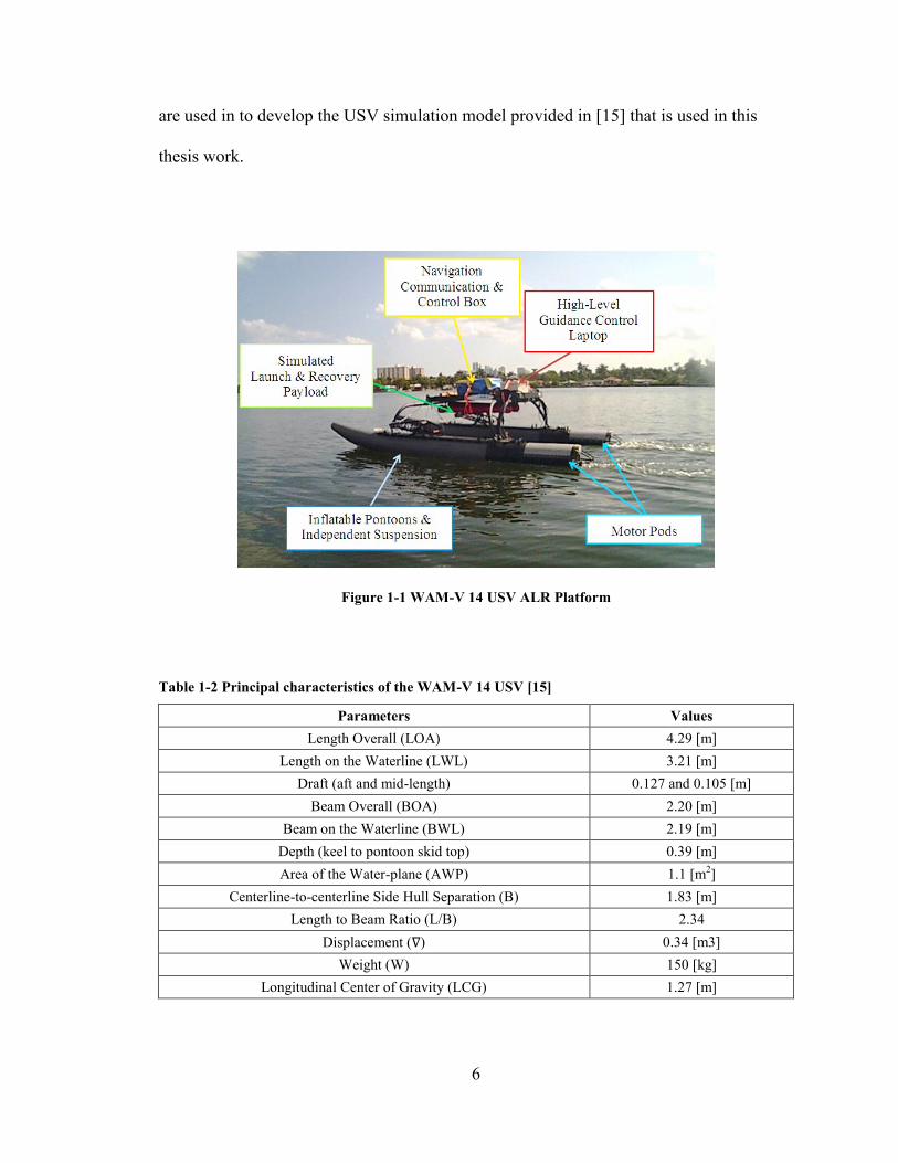
The suite of navigational sensors is comprised of an XSENS MTi-G INS/GPS and an
Ocean Server OS5000 digital compass package that are used to measure the USV’s
Compass heading, motion with an Inertial Measurement Unit (IMU) and position with a
GPS during operation. This USV state data is then published through an LCM channel at
a 10 [Hz] interval [16]. The compass sensor as specified by the manufacturer provides a
heading accuracy of 1 [deg] RMS within ±30 [deg] of sensor pitch. The INS/GPS sensor
as specified by the manufacturer to provide a Circular Error Probability (CEP) of 2 [m] is
published with LCM at a 10 [Hz] interval. The LLC receives this navigational and raw
sensor data and stores it along with the last provided guidance commands for post
processing. Figure 1-2 shows the NCC box configuration and guidance system interface
used for this project.
Figure 1-2 WAM-V 14 USV Navigation Communication & Control Box, Guidance and Supervisory
RC Control Diagram
Key: ─ Wired Connection , ∙∙∙ Wireless (RC & Wi-Fi), --- Ethernet, '<Text>_t’ LCM Message
Page 29
9
The WAM-V 14 USV Navigation Communication & Control Box, Guidance and
Supervisory RC Control Diagram shown in Figure 1-2, shows the RC controller and the
HLG controller Laptop on the left as outside of the NCC box transmitting commands
wirelessly. The HLG controller receives the vehicle state information USV_State_t from
the USV State Estimator process that is receiving navigational data from the digital
compass and INS/GPS. The USV_State_t message is published through LCM and the
HLG controller computes the required guidance commands to complete the current task.
The Guidance_Cmd_t messages are then published back to the NCC box where the LLC
takes the USV_State_t and Guidance_Cmd_t messages and determines the required
motor thrust for each motor pod, based on the implemented controller. These motor
signals are then sent to a Pulse Width Modulation (PWM) generator to be formatted into
RC PWM signals that can be read by the motor controllers, which is housed inside the
motor pods. On the far right side of the NCC box, there is an RC/Autonomous switch to
transfer control of the motor pods from Autonomous to RC for supervisory control. For
more information about the WAM-V 14 USV platform and the NCC box, refer to [15]
[16] [19].The HLG control laptop as shown in Figure 1-2 will be discussed in further as it
is part of Chapter 3.5.
1.2.3 Low-Level Control
The NCC box is designed in a modular fashion that allows any LLC designed to
interface with LCM that accepts heading and speed commands to be implemented and
tested immediately. For this project, several LLCs were tested and evaluated for an ALR
mission, by Klinger et.al. [15]. An Adaptive Back -Stepping controller was proposed and
evaluated against a Back-Stepping controller, and Proportional controller for speed set-
Page 30
10
point tracking control under unknown and transient drag and mass of the WAM-V 14
USV ALR platform. The proposed adaptive back-stepping controller showed good speed
tracking performance over the other tested controllers during all variable mass and drag
tests, conducted by Klinger.
1.2.4 Launch and Recovery Mechanism
ALR could not be possible without a physical mechanism to capture and deploy
the UUV. Several L&R mechanisms are currently being researched and tested for the
WAM-V 14 USV ALR platform. Sarda, et al. has presented some of the approaches that
are being researched for this platform in [20]. Many of Sarda’s approaches deal with the
problem how the UUV will be physically docked to a subsurface mobile docking
platform that is being towed by the USV ALR. This approach requires that the USV ALR
platform be ahead of the UUV to allow for capture a couple of meters the ocean surface
(3-5 [m]).
Based on Sarda’s proposed concept of docking, the HLG docking controller will
need to address the issues of coarse trajectory alignment for rendezvous-docking. Coarse
trajectory alignment is limited to be within a few meters of cross-track from the deployed
docking mechanism to the UUV. The limitation of coarse trajectory alignment is a
product of the maneuverability of the USV ALR platform and the towed docking
mechanism. The UUV’s own docking controller should handle fine trajectory alignments
for terminal docking, or a robust docking mechanism that can allow for docking within
the coarse trajectory alignment limitation.
Page 31
11
1.2.5 Unmanned Underwater Vehicle Tracking and Communications
The sensor system utilized for tracking, navigation and data transmission is
acoustics. Acoustics tracking and navigation systems can take the form of a Sonar, Long
Base Line (LBL), or Ultra Shot Baseline (USBL). Acoustics can also be used for
telemetry, command and control, and data transmission through acoustic modems.
For this project, a USBL acoustic navigation system is to be implemented on the
WAM-V in order to provide underwater tracking system, which measures the range,
azimuth, and elevation angles of a specific acoustic source. A USBL system is currently
being developed at FAU to provide the USV ALR platform with UUV tracking
capabilities. This system will provide the HLG controller the body fixed measured range
and bearing of the UUV. The exact specifications and approach of implementation of the
USBL system are still unknown at this time, but the system is expected to operate within
a range of 2000 meters and have a near Omni-directional field of view.
Communications between the USV and the UUV can be accomplished by
implementing an acoustic modem. Acoustic Communication Systems (ACOMMS)
modems allow operators to start, stop, alter and monitor the UUV while in a mission. The
data transfer has a limited bandwidth and low reliability due to ray bending effects,
marine life, and multipath issues of operating in a variable hydrodynamic environment.
Even with these issues, by implementing ACOMMS on board a USV ALR platform,
control commands and other capabilities can be added to implement a command and
control network from the ocean surface to the subsurface. ACOMMS such as Woods
Hole Oceanographic Institute (WHOI) micro-modem system are widely used in
autonomous maritime systems for multi-vehicle collaboration [21] [22]. For this project,
Page 32
12
ACOMMS is not implemented within the scope of this research; careful consideration
was made to allow for an ACOMMS implementation later in the project life cycle.
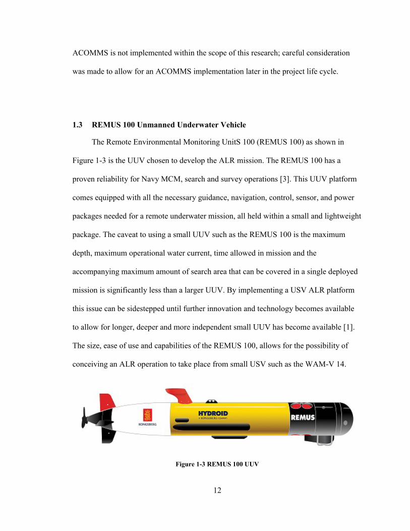
1.3 REMUS 100 Unmanned Underwater Vehicle
The Remote Environmental Monitoring UnitS 100 (REMUS 100) as shown in
Figure 1-3 is the UUV chosen to develop the ALR mission. The REMUS 100 has a
proven reliability for Navy MCM, search and survey operations [3]. This UUV platform
comes equipped with all the necessary guidance, navigation, control, sensor, and power
packages needed for a remote underwater mission, all held within a small and lightweight
package. The caveat to using a small UUV such as the REMUS 100 is the maximum
depth, maximum operational water current, time allowed in mission and the
accompanying maximum amount of search area that can be covered in a single deployed
mission is significantly less than a larger UUV. By implementing a USV ALR platform
this issue can be sidestepped until further innovation and technology becomes available
to allow for longer, deeper and more independent small UUV has become available [1].
The size, ease of use and capabilities of the REMUS 100, allows for the possibility of
conceiving an ALR operation to take place from small USV such as the WAM-V 14.
Figure 1-3 REMUS 100 UUV
Page 33
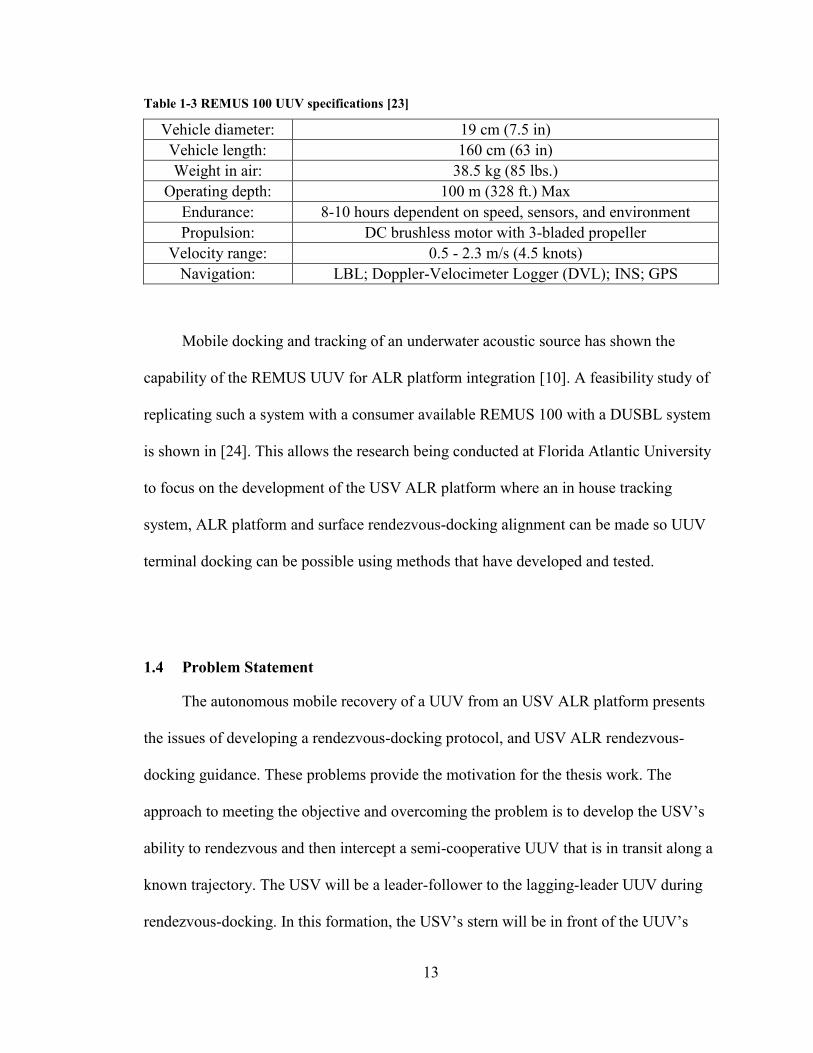
13
Table 1-3 REMUS 100 UUV specifications [23]
Vehicle diameter: 19 cm (7.5 in)
Vehicle length: 160 cm (63 in)
Weight in air: 38.5 kg (85 lbs.)
Operating depth: 100 m (328 ft.) Max
Endurance: 8-10 hours dependent on speed, sensors, and environment
Propulsion: DC brushless motor with 3-bladed propeller
Velocity range: 0.5 - 2.3 m/s (4.5 knots)
Navigation: LBL; Doppler-Velocimeter Logger (DVL); INS; GPS
Mobile docking and tracking of an underwater acoustic source has shown the
capability of the REMUS UUV for ALR platform integration [10]. A feasibility study of
replicating such a system with a consumer available REMUS 100 with a DUSBL system
is shown in [24]. This allows the research being conducted at Florida Atlantic University
to focus on the development of the USV ALR platform where an in house tracking
system, ALR platform and surface rendezvous-docking alignment can be made so UUV
terminal docking can be possible using methods that have developed and tested.
1.4 Problem Statement
The autonomous mobile recovery of a UUV from an USV ALR platform presents
the issues of developing a rendezvous-docking protocol, and USV ALR rendezvous-
docking guidance. These problems provide the motivation for the thesis work. The
approach to meeting the objective and overcoming the problem is to develop the USV’s
ability to rendezvous and then intercept a semi-cooperative UUV that is in transit along a
known trajectory. The USV will be a leader-follower to the lagging-leader UUV during
rendezvous-docking. In this formation, the USV’s stern will be in front of the UUV’s
Page 34
14
bow. This docking/ recovery formation is an operational constraint based upon the
current L&R mechanism design. The USV’s goal is to maximize the probability of a final
mobile docking maneuver made by the UUV, by making cross-track course trajectory
adjustments to align the L&R docking mechanism with the UUV. This ability is
accomplished by developing a Rendezvous-Docking Fuzzy Logic Guidance controller
that will generated ad-hoc Waypoint-Heading (a desired waypoint with a desired heading
constraint) goal for the USV to attempt in order to minimize the cross-track errors
between the USV and UUV. To guide the USV to the generated ad-hoc Waypoint-
Heading goal, a subsequent Waypoint-Heading Fuzzy Logic Guidance controller is
developed to provide the desired heading and speed commands to the LLC.
1.5 Contribution
The contribution of this thesis is to design, simulate and implement the HLG
controller for an ALR mission that will provide the desired guidance commands for the
USV ALR platform to intercept an UUV. The HLG controller will be developed by
layering two separate Fuzzy Logic (FL) controllers together. The top layer will determine
waypoint-heading goals that will intercept a UUV, which is underway along some
straight path trajectory. The bottom layer will develop the desired heading and speed
commands which are sent to the LLC of the USV. This bottom layer is designed so that
the USV ALR platform can achieve desired waypoint-heading goals for topside
objectives including, Transit, Deployment, and Search & Survey.
Page 35
15
1.6 Thesis Structure
Chapter 1 introduces the reader to the background and road map of the ALR
platform in the autonomous maritime system economy. Next, the reader was introduced
to the WAM-V 14 USV that is currently being researched as an ALR USV platform and
the systems that have and plan to be implemented and tested for an ALR mission with a
REMUS 100 UUV. The reader should have enough background to understand the
problem, which this thesis work is trying solve and understand the author’s contribute.
In Chapter 2, the author will review the relevant publications and work that is
currently ongoing in the autonomous maritime community for ALR, docking and
guidance. Fuzzy logic will be introduced as the means for developing guidance in an
ALR mission for a USV platform and the reader should then have enough background to
follow along with the development in following chapter.
Chapter 3 will examine the approach that the author took to use fuzzy logic in
simulations and testing the approach in the real world. The author will go through the
models used to simulate the WAV-V 14 and REMUS 100 to test the guidance controllers.
Then the author will go through the HLG control system implemented in the real world
for experimentation.
Chapter 4 will present the results of testing and simulation of the fuzzy logic
guidance controller and the real world experiments. This will be followed by brief
analysis and discussion of these results.
Page 36
16
Finally, chapter five will conclude this thesis work with the author’s own
conclusions about the outcome of the HLG controller and the recommendations for
continuing this work.
Page 37
17
2. Literature Review
To the knowledge of the author, there is only one published work on the subject of
ALR of a UUV from an USV platform , excluding the supporting papers directly related
to this research projects at Florida Atlantic University (FAU) in ALR, [14] [15] [20] [24].
In [25] the authors present a project that attempts to recover a passive UUV that is
floating at the sea surface by using a vision-based system aboard a USV. The USV
developed by the Autonomous Systems Laboratory at the Institute of Engineering of
Porto is designed to be able to dock with a REMUS UUV in lake or riverine
environments. The limitations of the vision-based system are a maximum operating
distance of 8 meters; UUV must breach the surface; The UUV’s relative position must be
known prior transiting into the area where vision based docking approach is feasible. The
vision based target identification and localization system, along with a ‘hybrid maneuver’
to align the USV with the passively floating UUV, showed capability to perform
rendezvous with a UUV floating at the surface from some test results. However, the
paper does not directly address an ALR mission comprised of UUV deployment, UMS
mission collaboration or physical retrieval, [25] provides a USV rendezvous process with
a UUV. The following sections review the work that has been published on efforts in
UMS collaboration, UUV docking guidance and control and USV guidance and control.
The last section will be a brief overview of Fuzzy Logic as it is the primary algorithm
used for developing guidance for the USV ALR platform.
Page 38
18
Though there is little published work on the subject of mobile ALR outside of the
current project at FAU, there are publications of UMS working collaboratively to
complete a mission. The following paragraphs will review some of the more relevant
work that has been done with H-UMS for search and survey applications. The H-UMS
collaborations are presented to provide context to the reader on the current state of the art
and further the consensus of a need for research of USV ALR platforms.
One function that USVs have been used in H-UMS operations is in tracking of an
UUV to provide navigation, communications and control. Using USBL systems, a USV
can track UUV(s) (vice versa) and use the data to improve underwater navigation, by
providing DGPS information augmented by the acoustic tracking [26]. In [27] the
authors describe an acoustic navigation scheme that incorporates surface sonobouys,
USVs and UUVs so that the UUVs can accurately navigate under water without needing
to resurface to acquire a GPS fix [27]. A tracking controller is presented in [28] to
demonstrate an USV that can track and follow an UUV that has an unknown trajectory
and speed using acoustics. The tracking controller utilizes a decoupled Proportional
Integral (PI) controller in heading and speed, while the HLG control uses Fuzzy logic to
maintain a desired safe distance from the UUV [28].
Hydrographic Survey and Mine Counter Measures assistance and collaboration are
another application of research in H-UMS missions by utilizing adaptive mission
planning and command. A USV operating in a command support function can relay
commands from mission command to control a UUV and adjust its mission objectives
based on recently gathered information to adapt the mission without necessarily needing
to recover the UUV. In [29] the authors address the problems of developing a cooperative
Page 39
19
H-UMS, and propose their approach to control a low-cost UUV to target a location by
using a one-way acoustic link.
2.1 Unmanned Maritime Vehicle Docking Guidance
Guidance of unmanned systems is a widely researched topic of interest in all
applications of robotics. The most common approach to this problem is Line of Sight
(LOS) guidance or a geodetic desired heading transform, equation 2.1.
𝜓𝑖 = atan2d(Δ𝑌𝑖, ΔXi) (2.1)
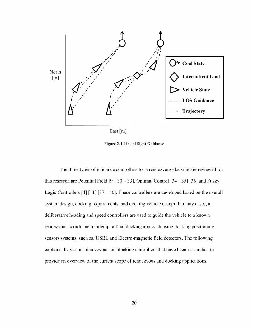
This method only requires geometry by utilizing the geodetic current position of
the vehicle (Xi, Yi) and final goal position (XGi, YGi
) to compute the current differential
position (ΔXi, ΔYi) and then determine the angle ψi (Heading)of the vector between them
as the desired compass set-point heading of the vehicle. 'atan2d’ is a Matlab function that
returns the four-quadrant inverse tangent in degrees, output range is [-180,180]. Using
this method of guidance will allow the vehicle to achieve the waypoint goal, but it does
not provide line/path following guidance to achieve a non-arbitrary final vehicle position
state (XGi, YGi
, ψGi), unless intermittent waypoints are used to consecutively guide the
vehicle from its initial state to the final desired state, as shown in Figure 2-1.
Page 40
20
Figure 2-1 Line of Sight Guidance
The three types of guidance controllers for a rendezvous-docking are reviewed for
this research are Potential Field [9] [30 – 33], Optimal Control [34] [35] [36] and Fuzzy
Logic Controllers [4] [11] [37 – 40]. These controllers are developed based on the overall
system design, docking requirements, and docking vehicle design. In many cases, a
deliberative heading and speed controllers are used to guide the vehicle to a known
rendezvous coordinate to attempt a final docking approach using docking positioning
sensors systems, such as, USBL and Electro-magnetic field detectors. The following
explains the various rendezvous and docking controllers that have been researched to
provide an overview of the current scope of rendezvous and docking applications.
North
[m]
East [m]
Goal State
Intermittent Goal
Vehicle State
LOS Guidance
Trajectory
Page 41
21
2.1.1 Potential Field
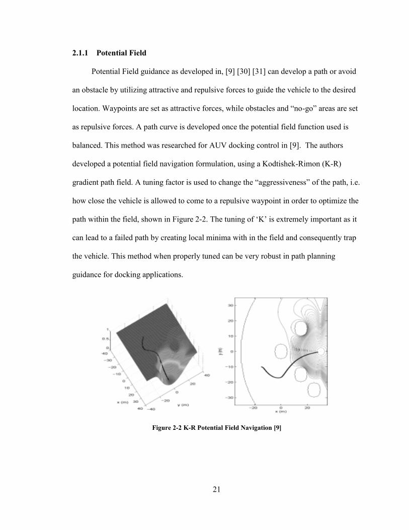
Potential Field guidance as developed in, [9] [30] [31] can develop a path or avoid
an obstacle by utilizing attractive and repulsive forces to guide the vehicle to the desired
location. Waypoints are set as attractive forces, while obstacles and “no-go” areas are set
as repulsive forces. A path curve is developed once the potential field function used is
balanced. This method was researched for AUV docking control in [9]. The authors
developed a potential field navigation formulation, using a Kodtishek-Rimon (K-R)
gradient path field. A tuning factor is used to change the “aggressiveness” of the path, i.e.
how close the vehicle is allowed to come to a repulsive waypoint in order to optimize the
path within the field, shown in Figure 2-2. The tuning of ‘K’ is extremely important as it
can lead to a failed path by creating local minima with in the field and consequently trap
the vehicle. This method when properly tuned can be very robust in path planning
guidance for docking applications.
Figure 2-2 K-R Potential Field Navigation [9]
Page 42
22
Other potential field strategies [32] [33] for path planning and docking have been
developed using various field functions, depending on the specific application, yet the
principles of potential field guidance controller are the same.
2.1.2 Optimal Control
An Optimal control is used to determine the most efficient and/ or safe trajectory
based on the optimization method utilized. A common optimization algorithm known as
the A* algorithm is a Heuristic search algorithm which improves the searching efficiency
by using the heuristic information to lead searching decision-making and guarantee the
path’s superiority simultaneously [34]. An A* path planner method is proposed in [35]
that can verify a previously planned path, generate a new path between successive goal
points and generate a path to the nearest point of a “safe” region. This method requires
extensive knowledge of an area in a readily available database, along with the
computational power to apply the A* search to the database. Research in SLAM
(Simultaneous Localization and Mapping) techniques [36] has improved the on-line
capabilities of using optimal controller for path planning.
2.1.3 Fuzzy Logic
Fuzzy Logic (FL), as described in [41 – 47], provides a robust, artificially
intelligent solution that model human linguistics and reasoning to the problem of ALR
mission guidance. FL is noted to be good for when input data and actuator control are
suboptimal or non-linear. Perhaps the most commonly used intelligent controller for
docking guidance is FL, due to its relatively easy formulation and implementation for
real-time operations on embedded control systems.
Page 43
23
FL controllers attempt to “mimic” human reasoning and logic by developing sets
of distributed membership functions across a range of possible inputs [4]. As described in
[48] [49] [50] human decision-making is somewhat fuzzy and not dependent on classical
Boolean logic. The figure below shows a set of normalized input membership functions
ranging from -1 to 1 for the possible error in a guidance controller.
Figure 2-3 Sample Cross Track (X Error) FUZZY Membership Functions, Fuzzy Logic Waypoint-
Heading Guidance Control
Each membership function in this example represented by a Gaussian distribution
function and defined accordingly to its input range. So, NB stands for a Negative Big X
Error, NS for Negative Small, Z for Zero, PS for Positive Small and PB for Positive Big.
The reason that the membership functions overlap and are not in discrete states is because
the point at which the input value changes from one state to the next is what some may
call a “fuzzy” relation. The known input variable is passed through these membership
functions in a process called fuzzification. This fuzzification process produces a fuzzified
value that is compared against a set of governing rules or fuzzy laws in which an
inference of logic can be made about the input state. During this process, sets of IF
Page 44
24
(AND, OR) statements along with some computational laws, produce an inference value
which is then defuzzified by the set of output membership functions to provide a
reasoned approximate output value.
One of the most practical reasons for using a fuzzy controller is that it does not
require any knowledge of a dynamic system in order to control it. Qualitative behavior of
the system’s operational limits is provided by employing an experienced operator or
“Expert” to develop the desired FL controller characterizes. The following text briefly
describes fuzzy logic controllers that have been developed for the rendezvous-docking
applications.
Many FAU researchers have developed UUV fuzzy logic docking controllers.
Many of these systems utilize USBL systems during docking attempts [4] [11] [37] [38]
[39] One approach to the rendezvous-docking control problem attempted [4] uses
heading, approach track, down track and cross track errors as input variables to the fuzzy
logic docking controller. A localized fuzzy docking map, shown in the figure below was
used to develop the fuzzy laws in order to define the heading and speed commands as the
vehicle moved toward the center of a ±45 [deg] docking cone. The magnitude and
direction of unknown current disturbances was a major factor in determining docking
success.
Page 45
25
Figure 2-4 Localized Goal Coordinate Transform & Localized Fuzzy Docking Map [4]
The localized fuzzy docking map can be applied to a docking station at any
location and orientation. This is due to the goal orientation coordinate transform so that
the inputs to the fuzzy docking map are relative to the docking station. It is noted that
when outside of the local docking map the heading goal is just LOS, this provides an
efficient way to get close enough to the final goal before applying the fuzzy docking map.
Since a rendezvous-docking controller can be considered as a high precision
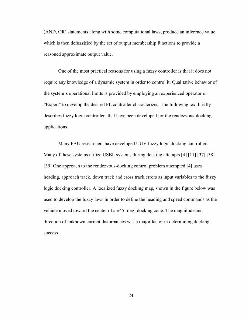
waypoint-heading controller. Another approach developed for an autonomous boat [40] is
reviewed. Three inputs into a FL controller are used: the goal centric position errors (X,
Y) along with the current vehicle heading. The results showed excellent performance, yet
the development and subsequent tuning of the fuzzy logic rules was intricate and time
consuming, in that formulation of 125 rules were used to compute the final desired
output. Utilizing so many rules requires more computational power, but when
Page 46
26
appropriately tuned the controller perform as expected. This approach brings much
insight into the development of fuzzy waypoint guidance for small ships.
Figure 2-5 Fuzzy Waypoint Guidance Diagram [40]
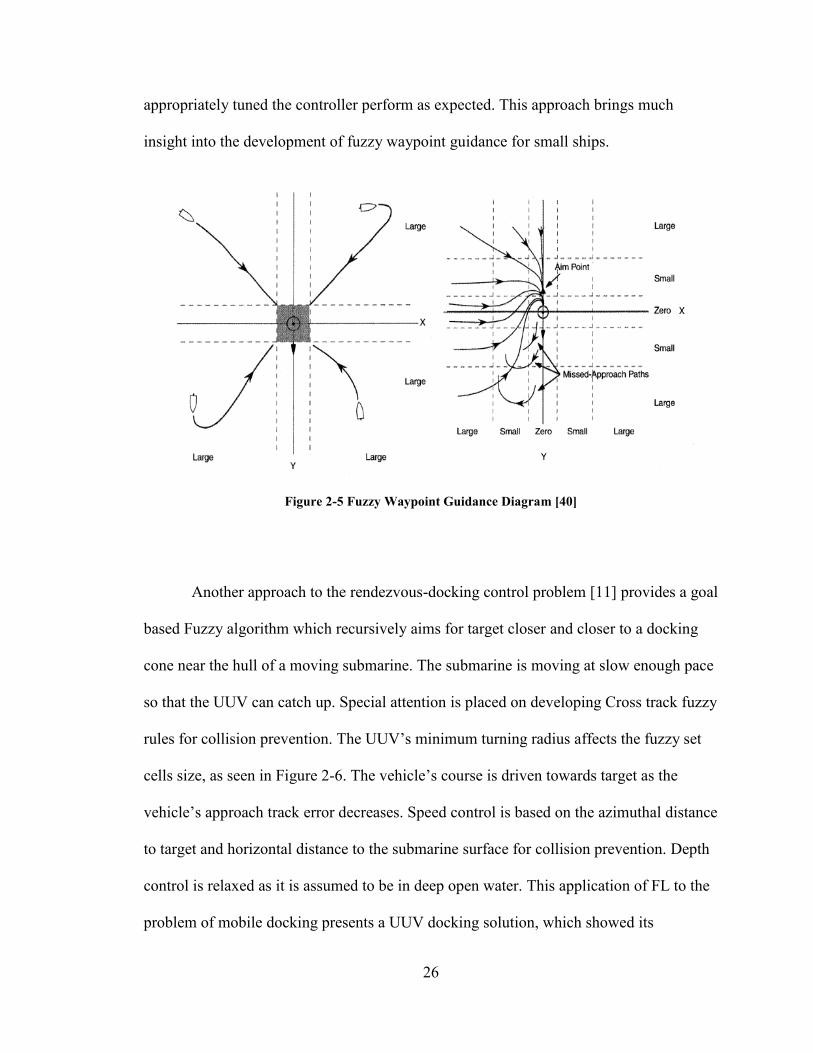
Another approach to the rendezvous-docking control problem [11] provides a goal
based Fuzzy algorithm which recursively aims for target closer and closer to a docking
cone near the hull of a moving submarine. The submarine is moving at slow enough pace
so that the UUV can catch up. Special attention is placed on developing Cross track fuzzy
rules for collision prevention. The UUV’s minimum turning radius affects the fuzzy set
cells size, as seen in Figure 2-6. The vehicle’s course is driven towards target as the
vehicle’s approach track error decreases. Speed control is based on the azimuthal distance
to target and horizontal distance to the submarine surface for collision prevention. Depth
control is relaxed as it is assumed to be in deep open water. This application of FL to the
problem of mobile docking presents a UUV docking solution, which showed its
Page 47
27
capability to dock with the mobile recovery mechanism or avoid possible collisions with
the submarines hull.
Figure 2-6 Fuzzy Rules Map for UUV Docking to a Moving Submarine [11]
The above controller methodologies’ pertaining to rendezvous-docking
applications is not intended to cover all available control laws in this study. The intention
is to examine fuzzy logic controllers in order to understand their research approaches,
findings, and results to further the area of research by choosing a suitable controller
methodology for the thesis work.
Page 48
28
3. Approach
The approach used to attempt to solve the problem of USV mobile rendezvous-
docking will be explained in this chapter. The constraints and operational scenarios will
be applied to isolate the specific problem that is to be solved. The method and model
used to solve the problem will be introduced along with the experiment setup and the
tests performed.
3.1 Constraints and Scenarios
For this thesis work, several constraints and assumptions are used to carry out the
development of the HLG controller for modeling and experimentation. These constraints
include the provided dynamic model of the USV, a simplified operational performance
model of a USBL system, a kinematic surge model of the UUV, and the assumption that
all systems are operating in ideal conditions with no environmental disturbances from
waves, currents or wind. In addition it is assumed that there are underwater
communication systems in place that can relay basic operating commands to the UUV
from the USV ALR platform, including Start, Stop, and Redirection (if needed). The
scenario that was created to develop this thesis work is the ALR mission as described in
Chapter 1. More specifically, an ALR mission concept of operations is developed to
guide the development of the ALR mission HLG and mission management architecture
Page 49
29
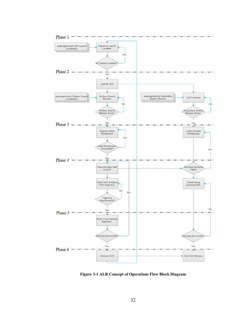
The USV will autonomously transit to an area of interest and then deploy the UUV
(Phase 1 of Figure 3-1). Once the UUV has launched from the USV both vessels will
perform their own search and surveillance mission, gathering mission critical data (Phase
2 of Figure 3-1). Once the search mission is complete or a new mission plan is passed
down from operational command, the USV will request an initial rendezvous with the
UUV (Phase 3 of Figure 3-1). Once both vehicles have reached their initial rendezvous
coordinates, they will enter into a rendezvous-docking protocol, which will start the
Rendezvous-Docking Fuzzy Logic Guidance control.
The rendezvous-docking protocol for the USV will begin by passing a docking path
(final docking rendezvous location) to the UUV which is a preprogramed location
developed by the operator during the development of the mission (Phase 3 of Figure 3-1).
The UUV loitering behind the USV at some range at the initial rendezvous coordinates
will then begin to traverse along the referenced docking path (Phase 4 of Figure 3-1. This
initial step of the rendezvous-docking protocol will set up an initial alignment of the
vehicles and allow them to be within the line of sight of the USBL so that the USV can
begin to receive the approximate measured positioning of the UUV.
The USBL tracking system aboard the USV will transmit a request message to the
appropriate UUV node and then wait for its reply. The appropriate UUV node is the
USV’s corresponding UUV. Using the total time of travel for the node to respond, the
USBL will calculate an azimuth angle, elevation angle, and range to the node with a
fixed-body reference frame. The operational range between the vehicles during the
rendezvous-docking protocol is set by the conservative constraints of the modeled USBL.
Page 50
30
It is assumed that the operational limitations of the USBL consist of range less than 2000
[m] and within +- 17 [deg] field of view (FOV) with a constant accuracy of +- 2 [deg]
[24].
The UUV’s tracking information from the USBL is utilized in the high-level
rendezvous-docking controller on the USV. The measured range, bearing and velocity
information of the UUV are used to determine the current trajectory of the UUV. This
trajectory information is then used to adjust the USV’s trajectory in order to align itself
with the UUV’s trajectory (Phase 4 of Figure 3-1). The protocol is developed such that
the approximate initial trajectories should point toward the final rendezvous location.
When the UUV and USV’s trajectories are aligned, the USV will begin to slow
down in order to reduce the range (approach track) between the vessels while maintaining
a synchronized trajectory (Phase 5 of Figure 3-1) Enroute rendezvous and docking of the
UUV should take place along the docking path trajectory before either vehicle reaches
the final rendezvous location. If enroute rendezvous and docking does not occur the final
rendezvous location will serve as the new initial rendezvous location to reattempt the
mission from phase 3. Otherwise, once the USV has successfully rendezvoused and
captured the UUV, the surface vessel can begin transiting to the next mission objective
and stop the REMUS’s mission to begin reprograming it (Phase 6 of Figure 3-1).
The HLG controller and accompanying ALR mission architecture, designed for the
WAM-V 14 USV platform and REMUS 100 UUV, can be general enough to allow for
implementation and modularity onto any H-UMS achieving an ALR mission. This can be
achieved by developing a model-free guidance controller that can be tuned manually for
Page 51
31
the particular expected dynamics of the H-UMS. FL is researched as a method for
applying a model-free guidance controller as a possible solution to the need of a HLG
controller for the USV ALR platform.
Page 52
32
Figure 3-1 ALR Concept of Operations Flow Block Diagram
Page 53
33
3.2 Systems Modeling for Simulation
The WAM-V 14 USV ALR platform is modeled to have a 3 DOF motion (Surge,
Sway, Yaw) and its appropriate dynamics have been characterized [14] [15] [51]. This
dynamic model is accompanied by a Back-stepping LLC and will be used in the
development and simulations of the HLG controller. In order to develop the HLG
controller, a simulation of the mission scenario must be developed. To accomplish this,
Simulink and Matlab are utilized to build and test the HLG controller in a mission
scenario. Figure 3-2 shows the proposed Simulink block diagram for the ALR mission
scenario. The proposed HLG controller currently has only three inputs, Desired
Waypoint-Heading goal, Current Vehicle (WAM-V 14) Position and the REMUS 100
Position and Track measured from the APS. The following sections will describe the
figure below in detail.
Figure 3-2 System Simulation for ALR Mission Scenario, Simulink Block Diagram
Page 54
34
3.2.1 Dynamic Model of WAM-V 14
Utilizing the WAM-V model and LLC block developed in [14] as the starting
point, a HLG controller block is developed and added to provide the desired speed and
heading set points (Ud,d). These set points are updated every simulation control cycle
loop (10 Hz). The output of this block provides the Xw, Yw position of the WAM-V used
as HLG control feedback and for plotting, the vehicle heading w and the vehicle
speed Uw, which are only used for plotting.
Figure 3-3 WAM-V Model & Low-Level Control Block
The dynamic model developed in [14] and used along with the developed back-
stepping LLC in [15] for the simulations are carried out in this thesis in order to develop
the WAM-V 14 USV’s HLG controller. For more information on the development of this
dynamic model and the LLC, refer to [15] [14].
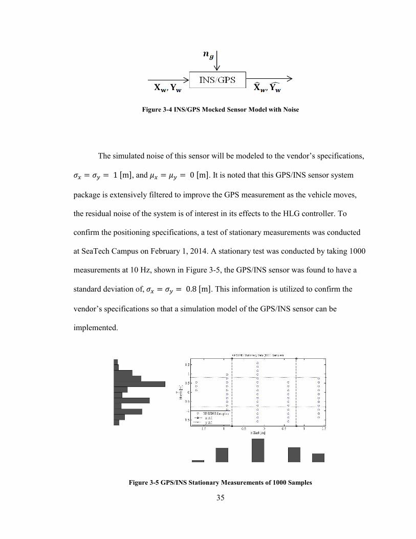
To model the GPS/INS information, the vehicles state information that is output
from the WAM-V model/ LLC block is fedback to the HLG controller. The WAM-V’s
position Xw, Yw is passed through a simulated INS/GPS sensor block to model this
information as measured position information, Xw, Yw by adding sensor noise, ng. The
INS/GPS system currently on the vehicle runs at a 10 Hz update rate.
Page 55
35
Figure 3-4 INS/GPS Mocked Sensor Model with Noise
The simulated noise of this sensor will be modeled to the vendor’s specifications,
𝜎𝑥 = 𝜎𝑦 = 1 [m], and 𝜇𝑥 = 𝜇𝑦 = 0 [m]. It is noted that this GPS/INS sensor system
package is extensively filtered to improve the GPS measurement as the vehicle moves,
the residual noise of the system is of interest in its effects to the HLG controller. To
confirm the positioning specifications, a test of stationary measurements was conducted
at SeaTech Campus on February 1, 2014. A stationary test was conducted by taking 1000
measurements at 10 Hz, shown in Figure 3-5, the GPS/INS sensor was found to have a
standard deviation of, 𝜎𝑥 = 𝜎𝑦 = 0.8 [m]. This information is utilized to confirm the
vendor’s specifications so that a simulation model of the GPS/INS sensor can be
implemented.
Figure 3-5 GPS/INS Stationary Measurements of 1000 Samples
Page 56
36
3.3 High-Level Guidance Controller Simulations
The following text will outline the design features of the simulated HLG
controllers. The HLG controller are developed using the Simulink simulation of the HLG
control sub-block, shown in Figure 3-6 is the sub-block details that corresponds to the
“High Level” Block mask in Figure 3-2.
Figure 3-6 Simulink model of High-level Guidance Controller
3.3.1 Waypoint-Heading Guidance Controller Development
The desired waypoint-heading goal input to the HLG controller block is a pre-
programmed set of geodetic NED waypoint-heading goals, which are programmed based
on the developed mission objectives. These waypoint-heading goals are used to progress
the mission forward and must be achieved in order for the mission to be successful
(success driven update), these goals can be overridden by applying a desired time allowed
to complete the particular objective/goal. These pre-programed waypoint-heading goals
include but are not limited to the drop off and initial rendezvous’ location of the REMUS
Page 57
37
100. The HLG controller will only receive a desired waypoint-heading command when it
is not tracking the REMUS 100 UUV for Rendezvous-Docking. The key for the
Rendezvous-Docking guidance controller to work properly is in the development of the
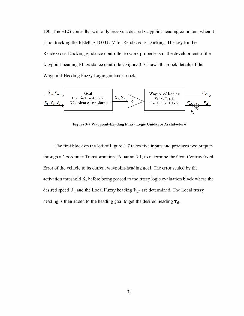
waypoint-heading FL guidance controller. Figure 3-7 shows the block details of the
Waypoint-Heading Fuzzy Logic guidance block.
Figure 3-7 Waypoint-Heading Fuzzy Logic Guidance Architecture
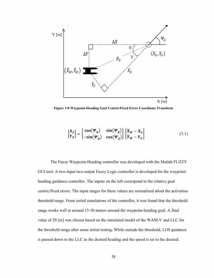
The first block on the left of Figure 3-7 takes five inputs and produces two outputs
through a Coordinate Transformation, Equation 3.1, to determine the Goal Centric/Fixed
Error of the vehicle to its current waypoint-heading goal. The error scaled by the
activation threshold K, before being passed to the fuzzy logic evaluation block where the
desired speed Ud and the Local Fuzzy heading LF are determined. The Local fuzzy
heading is then added to the heading goal to get the desired heading d.
K
Page 58
38
Figure 3-8 Waypoint-Heading Goal Centric/Fixed Error Coordinate Transform
[𝑿𝑬
𝒀𝑬] = [
𝐜𝐨𝐬(𝜳𝒈) 𝐬𝐢𝐧(𝜳𝒈)
−𝐬𝐢𝐧(𝜳𝒈) 𝐜𝐨𝐬(𝜳𝒈)] [
��𝑾 − 𝑿𝑮
��𝑾 − 𝒀𝑮
] (3.1)
The Fuzzy Waypoint-Heading controller was developed with the Matlab FUZZY
GUI tool. A two-input two-output Fuzzy Logic controller is developed for the waypoint-
heading guidance controller. The inputs on the left correspond to the relative goal
centric/fixed errors. The input ranges for these values are normalized about the activation
threshold range. From initial simulations of the controller, it was found that the threshold
range works well at around 15-30 meters around the waypoint-heading goal. A final
value of 20 [m] was chosen based on the simulated model of the WAM-V and LLC for
the threshold range after some initial testing. While outside the threshold, LOS guidance
is passed down to the LLC as the desired heading and the speed is set to the desired.
X [m]
Y [m]
Page 59
39
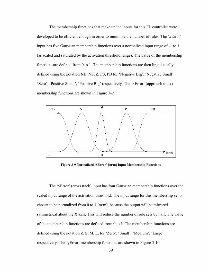
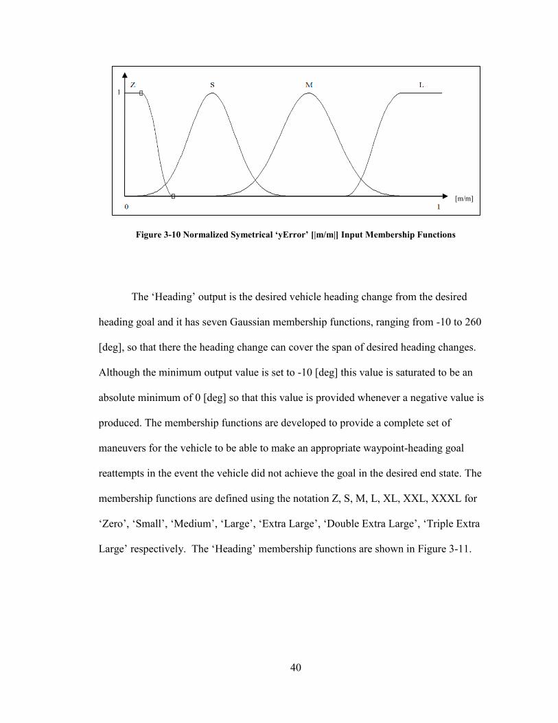
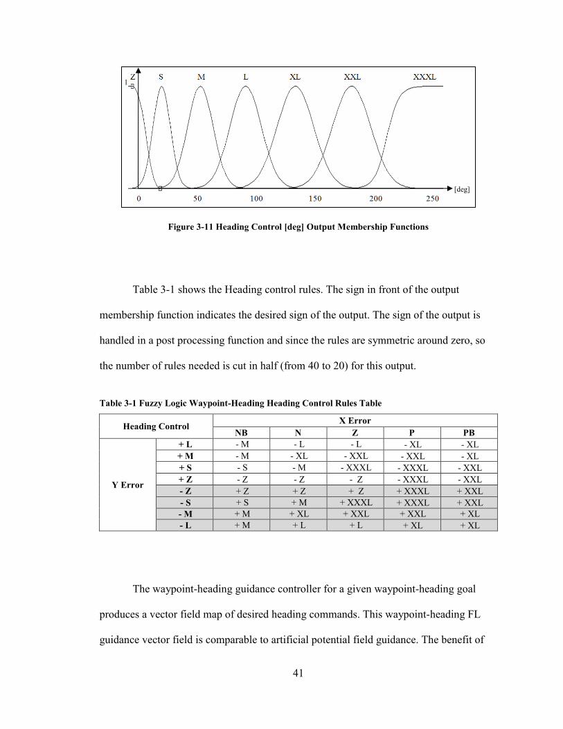
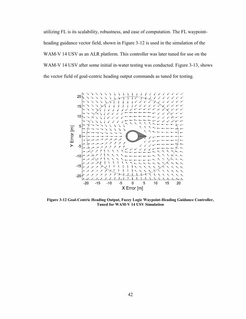
The membership functions that make up the inputs for this FL controller were
developed to be efficient enough in order to minimize the number of rules. The ‘xError’
input has five Gaussian membership functions over a normalized input range of -1 to 1
(as scaled and saturated by the activation threshold range). The value of the membership
functions are defined from 0 to 1. The membership functions are then linguistically
defined using the notation NB, NS, Z, PS, PB for ‘Negative Big’, ‘Negative Small’,
‘Zero’, ‘Positive Small’, ‘Positive Big’ respectively. The ‘xError’ (approach track)
membership functions are shown in Figure 3-9.
Figure 3-9 Normalized ‘xError’ [m/m] Input Membership Functions
The ‘yError’ (cross track) input has four Gaussian membership functions over the
scaled input range of the activation threshold. The input range for this membership set is
chosen to be normalized from 0 to 1 [m/m], because the output will be mirrored
symmetrical about the X axis. This will reduce the number of rule sets by half. The value
of the membership functions are defined from 0 to 1. The membership functions are
defined using the notation Z, S, M, L, for ‘Zero’, ‘Small’, ‘Medium’, ‘Large’
respectively. The ‘yError’ membership functions are shown in Figure 3-10.
1
[m/m]
Page 60
40
Figure 3-10 Normalized Symetrical ‘yError’ [|m/m|] Input Membership Functions
The ‘Heading’ output is the desired vehicle heading change from the desired
heading goal and it has seven Gaussian membership functions, ranging from -10 to 260
[deg], so that there the heading change can cover the span of desired heading changes.
Although the minimum output value is set to -10 [deg] this value is saturated to be an
absolute minimum of 0 [deg] so that this value is provided whenever a negative value is
produced. The membership functions are developed to provide a complete set of
maneuvers for the vehicle to be able to make an appropriate waypoint-heading goal
reattempts in the event the vehicle did not achieve the goal in the desired end state. The
membership functions are defined using the notation Z, S, M, L, XL, XXL, XXXL for
‘Zero’, ‘Small’, ‘Medium’, ‘Large’, ‘Extra Large’, ‘Double Extra Large’, ‘Triple Extra
Large’ respectively. The ‘Heading’ membership functions are shown in Figure 3-11.
1
[m/m]
Page 61
41
Figure 3-11 Heading Control [deg] Output Membership Functions
Table 3-1 shows the Heading control rules. The sign in front of the output
membership function indicates the desired sign of the output. The sign of the output is
handled in a post processing function and since the rules are symmetric around zero, so
the number of rules needed is cut in half (from 40 to 20) for this output.
Table 3-1 Fuzzy Logic Waypoint-Heading Heading Control Rules Table
Heading Control X Error
NB N Z P PB
Y Error
+ L - M - L - L - XL - XL
+ M - M - XL - XXL - XXL - XL
+ S - S - M - XXXL - XXXL - XXL
+ Z - Z - Z - Z - XXXL - XXL
- Z + Z + Z + Z + XXXL + XXL
- S + S + M + XXXL + XXXL + XXL
- M + M + XL + XXL + XXL + XL
- L + M + L + L + XL + XL
The waypoint-heading guidance controller for a given waypoint-heading goal
produces a vector field map of desired heading commands. This waypoint-heading FL
guidance vector field is comparable to artificial potential field guidance. The benefit of
1
[deg]
Page 62
42
utilizing FL is its scalability, robustness, and ease of computation. The FL waypoint-
heading guidance vector field, shown in Figure 3-12 is used in the simulation of the
WAM-V 14 USV as an ALR platform. This controller was later tuned for use on the
WAM-V 14 USV after some initial in-water testing was conducted. Figure 3-13, shows
the vector field of goal-centric heading output commands as tuned for testing.
Figure 3-12 Goal-Centric Heading Output, Fuzzy Logic Waypoint-Heading Guidance Controller,
Tuned for WAM-V 14 USV Simulation
Page 63
43
Figure 3-13 Goal-Centric Heading Output, Fuzzy Logic Waypoint-Heading Guidance Controller,
Tuned for WAM-V 14 USV Implementation
In addition to the heading output of the FL Waypoint-heading guidance controller,
speed guidance is developed. This second output provides speed commands for
maneuvering the vehicle into the waypoint-heading goal range as quickly as possible
without sacrificing maneuvering during simulation. In most cases during operation, the
vehicle’s speed will be determined by other mission constraints such as preset desired
transit speed, search/survey speed, allotted mission objective time, and optimization of
energy consumption, not considered in this work.
The ‘Speed Control’ output is the desired vehicle speed and it has three
trapezoidal membership functions, ranging from 0 to 3 [m/s]. The membership functions,
shown in Figure 3-14 are developed to provide a full range of speeds for the vehicle to be
able to make the appropriated heading maneuvers in order to achieve the desired end
state. The value of the membership functions are defined from 0 to 1. The membership
Page 64
44
functions are defined to designate the perceived vehicle speed using the notation ,’S’ ,
‘M’, ‘F’, for ‘Slow’, ‘Medium’, ‘Fast’, respectively.
Figure 3-14 ‘Speed Control’ [m/s] Output Membership Functions
The developed Fuzzy ‘Speed Control’ Rules are displayed in Table 3-2. This is a
draft of the fuzzy speed control rules developed for simulation and not tuned for USV
implementation. Again, due to symmetry the number of rules that are programmed are
cut in half in addition to the simplicity of the rules only 9 rules are needed (the subscript
denotes which common rule sets were used to make the table of rules). It is noted that
fewer rules can be developed by choosing a different pattern of common sets.
Table 3-2 Fuzzy Logic Waypoint-Heading Speed Control Rules Table
Speed Control X Error
NB N Z P PB
Y Error
L F F F F F
M F M M M F
S F M M M F
Z F S S M F
1
[m/s]
Page 65
45
Figure 3-15 Waypoint-Heading Fuzzy Logic Guidance, Desired Speed Output [m/s]
3.3.2 Waypoint-Heading Guidance Controller Simulation Testing
To test the developed Waypoint-Heading Guidance Controller, a single waypoint-
heading goal was provided to the simulated controller and the results of the test,
including the vehicle’s heading, desired heading error, heading goal error, position, and
goal position error, were used to evaluate the controller’s performance. To test the
controller, 300 waypoint-heading goals were simulated in series in order to evaluate the
entire operational field. To streamline this test procedure a Matlab testing script was
written to iterate through the series of waypoint-heading goals, pass them into the
simulation, start the simulation and receive the results. Another Matlab script was written
to provide post-processing analysis of the simulated test, which include the number of
attempts to achieve the waypoint-heading goal, and the number of tests that failed to
Page 66
46
achieve the waypoint-heading goal. The data from these tests was used to tune the
candidate Fuzzy Logic Waypoint-heading controller for further simulation. The finalized
controller as shown in the previous chapter, Chapter 3.3.1 is the prototype FL Waypoint-
Heading Guidance controller used in implementation and in water testing.
3.3.3 Rendezvous-Docking Guidance Controller Development
When the WAM-V is in Rendezvous-Docking mode, as shown in Figure 3-17, the
USBL APS block will be used to provide the measured body fixed track error of the
REMUS to the WAM-V. The Rendezvous-Docking FL Guidance controller will output a
desired waypoint-heading goal (𝑋𝐺𝑅𝐷, 𝑌𝐺𝑅𝐷
Ψ𝐺𝑅𝐷) which is at some distance ahead of the
WAM-V. The UUV’s course heading during rendezvous-docking is assumed to be
provided to the USV and updated by the acoustic modem. This developed waypoint-
heading goal is passed to the Waypoint-Heading FL guidance controller so that the
WAM-V 14 USV will begin to align its trajectory so that the cross-track errors of the
vehicles will be minimized. Figure 3-16, shows a concept of how the developed
waypoint-heading goal (Ring with an arrow head) will guide the WAM-V’s last
trajectory (dotted line) to align with the measured UUV’s trajectory (striped line) based
on the last measured range and bearing (stripped-dotted line).
Figure 3-16 Concept of Rendezvous-Docking Guidance
t0 t1 t2 t3
t3 t2
t1 t0
Page 67
47
Figure 3-17 Acoustic Positioning System during Rendezvous-Docking Mode
The Position and Track of the REMUS 100 UUV simulation block, shown in
Figure 3-2 is a simulation of the USBL Acoustic Positioning System (APS) that will be
onboard the WAM-V with unspecified operational characteristics. The USBL system
simulation block will provide the WAM-V body fixed range and bearing of the REMUS
100 within a constrained FOV= ±17.5 [deg]. As the FAU USBL will provide a larger
FOV, this constraint simulates a worst-case scenario. The simulation USBL block
provides a measurement update interval of 8 [sec] while in rendezvous-docking mode.
The USBL block will compute the 2D (North-East plane) range ��𝑅 and the bearing
𝜃𝑅 information. The REMUS 100 Track block, show in Figure 3-2 is a referenced time-
series array of position information, (𝑋𝑅 , 𝑌𝑅 , Ψ𝑅)(𝑡) from previous simulations of the
REMUS 100.
FOV
FOV
Page 68
48
The measured range of the UUV from the USV ALR platform is input into the
‘Range’ membership function set. The membership function set is scaled from 0 – 100
[m] (this scale is an initial assessment and can be tuned later) and is comprised of three
triangular functions and one trapezoidal function. The membership functions, shown in
Figure 3-19 are developed to provide a linguistic range to UUV inference. The value of
the membership functions are defined from 0 to 1. The membership functions are defined
to designate the perceived vehicle range using the notation ,’D’ , ‘C’, ‘F’, and ‘VF’ for
‘Docked’, ‘Close’, ‘Far’, and ‘Very Far’, respectively.
Figure 3-18 Rendezvous-Docking Controller, ‘Range’ [m] Input Membership Functions
The measured bearing (taken from the stern, 180 [deg]) of the UUV from the
USV ALR platform is input into the ‘Bearing’ membership function set. The
membership function set is scaled from -15 - 15 [deg]. This scale is an initial assessment
of expected bearing alignment based on the simulated USBL, and can be altered later for
the FAU USBL system that will be implemented on the USV. Figure 3-19 shows the
orientation of the USBL and as it relates the input range. The input is comprised of five
1
[m]
Page 69
49
triangular membership functions, shown in Figure 3-20 are developed to provide a
linguistic inference of the bearing to UUV. The value of the membership functions are
defined from 0 to 1. The membership functions are defined to designate the perceived
vehicle bearing using the notation ,’LN’ , ‘N’, ‘Z’, ‘P’ and ‘LP’ for ‘Large Negative’ ,
‘Negative’, ‘Z’, ‘Positive’ and ‘Large Positive’, respectively.
Figure 3-19 WAM-V 14 USV ALR Platform, USBL Bearing Measurement Configuration
Figure 3-20 Rendezvous-Docking Controller, 'Bearing' [deg] Input Membership Functions
-15
1
[deg]
15
Page 70
50
The FL Rendezvous- Docking Guidance controller ‘Y’ membership output set,
shown in Figure 3-21 uses three triangular membership functions and two trapezoidal
membership functions. This membership function set is scaled from -3 - 3 [m], but this
scaling can be altered to allow for a more aggressive cross-track approach. The
membership functions are defined to designate the desired ad-hoc cross-track using the
linguistic notation ,’L’ , ‘SL’, ‘Z’, ‘R’ and R’ for ‘Left’ , ‘Slight Left’, ‘Zero’, ‘Slight
Right’ and ‘Right’, respectively. This notation represents ‘Port’, ‘Port-Bow’, ‘Bow’,
‘Starboard-Bow’ and ‘Starboard’ in reference to the USV.
Figure 3-21 Rendezvous-Docking Controller, 'Y' [m] (cross-track) Output Membership Functions
The FL Rendezvous- Docking Guidance controller ‘X’ membership output set,
shown in Figure 3-22 uses three triangular membership functions. This output
membership function set scaled from 10 to 15 [m]. The membership functions are defined
to designate the desired ad-hoc along-track using the linguistic notation ,’C’ , ‘M’, and
‘F’ for ‘Close’ , ‘Medium’, and ‘Far’, respectively.
-3
1
[m]
3
Page 71
51
Figure 3-22 Rendezvous-Docking Controller, 'X' [m] (along-track) Output Membership Functions
In addition to the waypoint goal output, a Rendezvous- Docking Guidance
‘Speed’ controller membership set, shown in Figure 3-23 uses three trapezoidal
membership functions. This membership function set is scaled from 1 to 2 [m/s], so that
the USV can increase its speed so that it may maintain or decrease the rate of approach
track convergence. The membership functions are defined to designate the desired speed
to the developed waypoint-heading controller using the linguistic notation ,’S’ , ‘M’, and
‘F’ for ‘Slow’ , ‘Medium’, and ‘Fast’, respectively.
Figure 3-23 Rendezvous-Docking Controller, 'Speed' [m/s] Output Membership Functions
10 15
1
[m]
1
[m/s]
Page 72
52
The three output membership sets from the FL Rendezvous-Docking Controller,
‘Y’ (cross-track), ‘X’ (along-track), and ‘Speed’. The ‘X’, ‘Y’ membership sets provide
the desired ad-hoc waypoint in front of the USV and the ‘Speed’ membership set allows
the USV to slow down when alignment is adjusted for docking and to also speed up when
course adjustment is needed. The Rule set that is used to determine the Fuzzy inference
for this controller is provided in Table 3-3, Table 3-4, and Table 3-5. The evaluated
output for overall expected inputs for the Rendezvous-Docking controller is displayed in
Figure 3-24 to Figure 3-26.
Table 3-3 Fuzzy Logic Rendezvous-Docking Controller, 'Y' output Rules
Y Bearing
LN N Z P LP
Range
D SL Z Z Z SR
C SL SL Z SR SR
F L SL Z SR R
VF L L Z R R
Figure 3-24 Evaluated Y Goal [m] Output, Fuzzy Logic Rendezvous-Docking Guidance Controller
Range [m] Bearing [deg]
Y [m]
Page 73
53
Table 3-4 Fuzzy Logic Rendezvous-Docking Controller, 'X' output Rules
X Bearing
LN N Z P LP
Range
D C C F C C
C C M F M C
F M M F M M
VF F F F F F
Figure 3-25 Evaluated X Goal [m] Output, Fuzzy Logic Rendezvous-Docking Guidance Controller
Table 3-5 Fuzzy Logic Rendezvous-Docking Controller, 'Speed' output Rules
Speed Bearing
LN N Z P LP
Range
D F F S F F
C M M S M M
F M M S M M
VF S S S S S
Range [m] Bearing [deg]
X [m]
Page 74
54
Figure 3-26 Evaluated Speed [m/s] Output, Fuzzy Logic Rendezvous-Docking Guidance Controller
3.3.4 Rendezvous-Docking Guidance Controller Simulation Testing
An operational field of test conditions was simulated to evaluate the candidate FL
Rendezvous-Docking Guidance controller. In this case, the Variables tested were initial
offset of the UUV to the USV, along with effects of measurement noise and controller
variations to establish the best candidate for implementation. The candidate FL
Rendezvous-Docking controller was developed under the assumption that both vehicles
are within some initial range to one another, located near an initial rendezvous waypoint.
Due to the USBL system’s limited directionality, and the ALR mechanism’s
directionality, the USV will be initially located down range of that initial rendezvous
waypoint. To test the controller’s assumptions and constraints, a series of initial UUV
offsets to the USV were considered to test the ability of the candidate controller to
converge the vehicle which is following a straight line trajectory starting from an initial
offset location of 250 possible positions, as shown in Figure 3-27.
Range [m] Bearing [deg]
Speed [m/s]
Page 75
55
Figure 3-27 Fuzzy Logic Rendezvous-Docking Guidance Controller, UUV Initial Offset Simulation
Tests
Page 76
56
3.4 High-Level Guidance System Implementation & Experimentation
In this section, the method and approach to implementing the FL guidance
controllers is described as it pertains to the implementation on the WAM-V 14 USV ALR
platform. The WAM-V 14 USV ALR mission architecture as implemented in MATLAB
is described in Chapter 3.4.1 and the testing and experimentation method used to evaluate
the FL Waypoint-Heading Guidance controller is described in Chapter 3.4.2.
3.4.1 High-Level Autonomous Launch & Recovery Mission Architecture
The high-level guidance system architecture for the WAM-V 14 USV ALR
platform is based on multi-layered behavior. A collection of behaviors is used to achieve
a set of objectives. Each behavior receives an input from a sensor and/or another
behavior, the behavior then sends outputs to other behaviors or agents within the network
to achieve the desired task of the objective. Using preprogramed arbitration rules, this
system relies on reactivity to achieve its objectives in real-time. This architecture was
chosen because it fit the ALR mission scenario and desired operational characteristics.
At the top layer of the HLG system architecture is the Mission Controller, which
is responsible for delegating what the current mission objective is while keeping track of
the overall mission. This control layer simply iterates through a priori mission plan for
the ALR mission. These objectives include, “Launch UUV”, “USV Mission”, “Locate
UUV”, and “Recover UUV”.
The second layer consists of five behaviors of the USV mission. These behaviors
are general operation modes programmed into the controller such as, “Transit To”,
Page 77
57
“Deploy”, “Loiter At”, “Rendezvous”, and “Retrieve”. Mission behaviors are separated
into individual tasks to be controlled by the Motion Control system layer.
The specific ALR mission protocol occurs during the “Rendezvous” behavior of
the “locate UUV” objective, as the USV will locate its UUV by periodically receiving
UUV vehicle state information (Latitude, Longitude, Speed, and Heading) from
ACOMMS. ACOMMS is used when the UUV is out of the FOV of the USBL on the
USV, but was not implemented for this thesis work. Once the USV is within an
acceptable initial trajectory offset (Cross-track and Approach-track) the motion control
layer uses the FL Rendezvous-Docking controller to maneuver the USV to be within the
desired docking trajectory alignment. This will prompt the “Retrieve” behavior of the
“Recover UUV” objective where terminal docking guidance used by the UUV. Figure
3-28 shows the proposed system architecture. At this time, only part of this architecture
is implemented on the WAM-V 14 USV to allow for testing of the waypoint-heading
guidance controller, this includes the “Launch” and “USV Mission” portion of the
architecture; the rest of system architecture shown in Figure 3-28 is conceptual.
Page 78
58
Figure 3-28 WAM-V 14 USV ALR Mission, Behavior Based Architecture
The ALR mission is pre-programmed, so that all of the mission objectives are
known and the operator provides a safe path (waypoint to waypoint) for the vehicle to
follow, this ‘safe path’ arbitration can be another added behavior layer for future work.
Mission supervision and objective overrides can be implemented from a base station
(within Wi-Fi range) for the mission by setting up and transmitting LCM mission control
layer package(s) to/from the HLG controller, this is left as an option to be implemented
later on, however the capability is already in place.
Launch UUV USV Mission Locate UUV Recover UUV
Transit To Deploy Loiter At Retrieve Rendezvous
Fuzzy Logic Waypoint-
Heading Controller
Fuzzy Logic Rendezvous-
Docking Controller
Publish L&R Mechanism
Control Commands
Publish Low-Level Controller
Commands Publish Micro-Modem
Commands
Page 79
59
3.4.2 High-Level Guidance System Architecture, Communication Implementation
The high-level guidance system for the USV’s ALR mission, which was
implemented within the Matlab environment, was developed to operate as a real-time
high-level controller. Matlab provides a high-level computational language and
interactive environment for numerical computation, visualization, and programming.
Using Matlab's tools and functions allows for simulation and implementation provided a
faster approach to prototyping over traditional programming languages, such as C/C++
[52]. In order to run the HLG system through Matlab, a 32 bit Windows 7 laptop was
used, and depending upon the communications interface between the HLG system and
the USV’s NCC box, this provided the option to place the HLG laptop on the USV or at a
location within wireless operational range such as a chase vessel. Initial implementation
tests were conducted with the HLG laptop in a chase vessel so that Matlab mission script
changes could be made between tests.
Figure 3-30 shows the implemented communications interfaces for all systems
involved in the ALR mission. The WAM-V 14 USV systems would encompass the HLG
system, Communications, L&R mechanism and the NCC box. WAM-V 14 USV state
data (heading, speed, GPS coordinates, etc.) and control command signals are transmitted
over through the W-LAN for the ALR mission. Along with the W-LAN communications,
a RF modem and communications protocol, shown in Figure 3-30 is presented as a back-
up wireless communications implementation (Future development), which would require
a NMEA string to transmit HLG commands and receive vehicle state data from the NCC
box. The ALR mission as described in Chapter 3.1 required acoustic communications,
Page 80
60
through the WHOI micro modem this can be accomplished, but was not implemented on
the WAM-V during any testing as of HLG system.
The control communications between the USV’s NCC box and the HLG laptop
can be set up in one of two ways. The first possible setup for the control communications
uses a message passing protocol over a dedicated W-LAN (Wireless local-area
network),and the second possible setup for the control communications uses RF by
transmitting and receiving message strings based on a NMEA standard. Currently both
types of communication interfaces are physically supported by the control box. However,
the LLC that has been developed for the ACCeSS project as of now only supports W-
LAN message passing protocol.
Using W-LAN for the control interface can implemented by a wired Ethernet
connection or a wireless connection through the Wi-Fi router in the NCC box on the
USV. During, testing and developed, having quick access to the HLG laptop allows for
quick changes to the mission script and or behavior functions. Therefore, placing the
HLG laptop on the USV requires the chase vessel have a command laptop that can run
virtual desktop from the vessel within Wi-Fi range to be able to start and stop the HLG
Matlab processes. Regardless of how the HLG laptop is implemented for testing on the
USV, the communication between the HLG and LLC requires setting up the message
passing protocol known as LCM to work with the Matlab mission script.
Page 81
61
Figure 3-29 Communication interfaces between the High-Level Guidance laptop, the UUV and, the
USV’s NCC box
3.4.2.1 Local Area Network Communications: LCM Implementation
In order to interface the HLG system built within Matlab with the LLC and the
USV’s INS/GPS systems, a message passing protocol is used known as LCM. LCM is a
set of libraries and tools for message passing and data marshalling, targeted at real-time
USV USBL
USBL Sensor
Module
High-Level Control Communication System
W-LAN
RF Modem
Micro
Modem
Mission Control Layer
Behavior Control
Layer
Motion Control Layer
Data Storage
LCM
Data Display
Serial Port
NEMA
INS/GPS, Compass
Low-Level Controller
USV NCC Box UUV
Vehicle Status (position, heading, speed)
Redirection and mission modification
Control Commands
UDP
LCM
L&R Recovery Mechanism Control
USV L&R
Page 82
62
systems where high-bandwidth and low latency are critical. It provides a publish/
subscribe message passing model and automatic marshalling code generation with
bindings for applications in a variety of programming languages, including Matlab
(Java), C/C++ , and others [18].
The LCM communications architecture was implemented to connect the HLG
laptop to the NCC box and LLC using two methods. The first implementation of LCM
within Matlab that was developed uses Matlab Executable (MEX) Function to run a LCM
C++ code subroutine with the LCM C++ bindings. However, this MEX subroutine
method was found through testing to create a bottleneck during the repeated subscription
(retrial) of published vehicle state data by the NCC box. This MEX subroutine method
was found to require more resources, which subsequently reduces the number of HLG
computations per update cycle and sometimes causing communications system blackouts
due to issues with resource allocation. The second implementation method of LCM
within Matlab developed for the ALR mission uses Java bindings as described by the
LCM Matlab documentation. The Java binding allow for more efficient and robust LCM
functionality within Matlab.
Using Matlab’s MEX development tools, a C++ subroutine was developed to
create an instance of LCM. At a call of the function during a “Transit To” behavior,
Matlab executes the C++ LCM instance, subscribes to the IMU/GPS and Compass
channels and listens for the current sensor data. This data processed by the motion control
layer updates the publishing MEX subroutine callback function that is waiting to being
published upon a timer event. Utilizing a timer function in Matlab, the HLG command is
Page 83
63
published at a consistent interval of 1 [Hz]. Separate MEX subroutines are used for IMU/
GPS and Compass sensor data, which is individually requested at the beginning of every
instance of the HLG control loop. The IMU/GPS and Compass sensor data is published at
10 [Hz], the MEX function is developed to open a subscription upon each call in order to
listen to each subscribed channel for up to 0.13 [sec] for each separate channel. If no
message is received on the channel within the allotted time window, the previous sensor
data is used. This form of implementation is very inefficient, slow and can become
resource intensive after many consecutive calls.
After it was determined that the MEX Subroutine implementation was
suboptimal, the LCM Java bindings method was tested and found to provide a more
robust and efficient LCM implementation. The Matlab java bindings allowed for simple
in line function calls of the LCM code to set up the LCM subscription and publication
channels and only a single in-line function placed in the HLG Matlab script control loop
to accept the entire LCM message structure published by the NCC box. This allows for
complete USV state data collection and provides a message buffer to collect all published
data in order to evaluate the full state of the USV’s ALR system.
Page 84
64
3.5 High-level Controller Experiment
Decoupled testing of the ALR mission’s respective guidance controllers, waypoint-
heading and rendezvous-docking guidance are conducted to troubleshoot and debug the
system, layer by layer. This testing scheme requires persistent development of all ALR
systems before a full test of the ALR mission. Due to varying timelines of system
development and code implementation, only the FL Waypoint-Heading guidance control
layer, which directly interfaces with the LLC by providing the desired heading, and speed
commands for the WAM-V 14 USV ALR platform was tested.
3.5.1 Experimental Operation, WAM-V 14 USV ALR platform
Ideally, future testing and implementation should have all systems placed on the
USV as shown in Figure 3-30 but during initial prototyping and systems integration, the
HLG laptop was placed on the chase vessel as shown in Figure 3-31 so the tested code
can be debugged between tests.
Page 85
65
Figure 3-30 USV Experiment Operational Setup, HLG system onboard USV with Mission Control
and Telemetry CPU on Chase vessel
Figure 3-31 USV Operational Experiment Setup, HLG system onboard Chase Vessel
NCC Box
USBL &
Micro-Modem
ALR
Mechanism
NCC Box
HLG System
CPU
USBL &
Micro-Modem
ALR
Mechanism
Wi-Fi
ALR Mission
Control &
Telemetry CPU
Chase Vessel
Wi-Fi
HLG System
CPU
Chase Vessel
Page 86
66
Over three days of testing, February 3rd
, 10th
, and the 25th
, the USV’s HLG
laptop’s location was changed from being placed on the chase vehicle to on the USV.
This change was found to be negligible as the HLG system connection to the NCC box
through Wi-Fi on the W-LAN did not change. Both setups allowed for starting, stopping
and monitoring the HLG system test from the chase vessel. However, issues with LCM
blackouts occurred during some tests operated with a virtual desktop CPU on the chase
vessel connected over this Wi-Fi W-LAN during tests that placed the HLG system on the
USV.
The LCM blackout issue was caused by monitoring the test data traffic over the
virtual desktop connection, which limited the bandwidth available over the W-LAN and
caused the HLG system to stop temporarily as it waited for an instance of the LCM MEX
subroutine to connect to the appropriate channel and receive the desired USV’s state. To
remedy the problem during the rest of the day of testing, the virtual desktop login
procedure was limited only at the beginning and end of each test. In addition, a more
efficient and robust solution to overcome this problem was devised by utilizing the JAVA
implementation of LCM in Matlab.
3.5.2 Testing Location
In-water tests were conducted at North Hollywood Lake, Hollywood Florida,
shown in Figure 3-32. This testing location provides a large area for testing the USV with
little boating vessel traffic. The reference Latitude (26.016401 deg) and Longitude (-
80.122932 deg) position was used as the North East Down referenced origin for testing at
this location. This reference GPS location point (see Figure 3-32) is at the end of a
Page 87
67
floating dock used to deploy the vehicle at the beginning of certain tests, where consistent
initial starting position is desirable. This testing location was chosen for its relatively
consistent sea-state, normally between 0-1. However, this location is also known to have
10-15 knot winds and high gusts year round.
Figure 3-32 WAM-V 14 USV High-Level Guidance Control Testing Location, North Hollywood Lake
[Google Earth]
3.5.3 Testing Procedure, Fuzzy Logic Waypoint-Heading Guidance Controller
A single waypoint and a series of heading goals were chosen to evaluate the
implemented FL Waypoint-Heading Guidance controller. This required that the vehicle
began each waypoint-heading goal test near the NED origin, referenced GPS at end of
floating dock. The proposed ideal tests are shown in Figure 3-33, and include one
waypoint located 60 [m] east from the dock, and six desired heading goals.
Page 88
68
Figure 3-33 Proposed Ideal Tests of the Fuzzy Logic Waypoint-Heading Guidance Controller, (Blue
line: Lake boundary, Green Line: Start-to-Goal Vector, Black Arrows: Goal headings).
Testing of the Fuzzy Logic Waypoint-Heading Guidance controller at given
Waypoint (X, Y) with the desired heading Ψm was developed for the purposes of tuning
the scale of the fuzzy logic guidance range via the fuzzy logic waypoint-heading
guidance scaling factor ‘Kn’, refer to Chapter 3.3.1 for more detail. Tests were conducted
at incrementally increasing values of Kn, e.g. Kn = 20 m ,30 m ,40 m to experimentally
determine the optimal value of ‘Kn’, based on the USV’s implemented LLCi and
operating dynamics. A generic table of the testing parameters shown in Table 3-6 is used
for testing procedure reference for the series of tests conducted.
Page 89
69
Table 3-6 Generic Testing Parameters, Fuzzy Logic Waypoint-Heading Guidance Controller
𝐖𝐚𝐲𝐩𝐨𝐢𝐧𝐭 (𝐗, 𝐘)
𝐋𝐋𝐂𝟏 𝐋𝐋𝐂𝟐 𝐋𝐋𝐂𝟑
𝐊𝟏 𝐊𝟐 … 𝐊𝐧 𝐊𝟏 𝐊𝟐 … 𝐊𝐧 𝐊𝟏 𝐊𝟐 … 𝐊𝐧
Ψ1 Ψ1 Ψ1 Ψ1 Ψ1 Ψ1 Ψ1 Ψ1 Ψ1 Ψ1 Ψ1 Ψ1
Ψ2 Ψ2 Ψ2 Ψ2 Ψ2 Ψ2 Ψ2 Ψ2 Ψ2 Ψ2 Ψ2 Ψ2
: : : : : : : : : : : :
Ψm Ψm Ψm Ψm Ψm Ψm Ψm Ψm Ψm Ψm Ψm Ψm
From this test procedure, the number of tests that can be conducted can grow very
quickly. So in order to limit the number of tests, two fuzzy logic waypoint-heading
guidance scaling factors (Kn = 20, 30 [m]) were tested with three heading goals
(Ψm = 30, 150, 270 [deg]) at one waypoint using the three different LLCs. This set of
at-least eighteen tests will allow for the evaluation of the developed fuzzy logic
waypoint-heading guidance controller to guide the USV to the desired waypoint-heading
goal. In addition, these tests will provide the best case for determining the ideal fuzzy
logic waypoint-heading guidance scaling factor for the variety of LLCs and vehicle
dynamics, and lastly these tests will also allow for the direct comparison of each LLC to
operate as commanded in this operational environment.
Page 90
70
4. Results
4.1 Simulations
The developed guidance controllers were simulated and tested in the Matlab and
Simulink environment, as described in Chapter 3. The testing for the waypoint-heading
guidance and rendezvous-docking controllers are described in 4.1.1 and 4.1.2
respectively.
4.1.1 Waypoint-Heading Guidance Controller
The waypoint-heading fuzzy logic guidance controller was tested by placing the
WAM-V 14 USV around the edge of the fuzzy logic input range with different initial
LOS heading angles in order to simulate the vehicle entering the fuzzy logic guidance
range from the LOS guidance. Placing the vehicle around the waypoint-heading goal on a
circle at 6 [deg] intervals provides mapping of the waypoint-heading guidance
trajectories. Figure 4-1 shows the WAM-V 14 USV trajectories using the waypoint-
heading controller. The developed guidance controller was able to achieve the waypoint-
heading goal coming from all initial LOS angles. The path lines created by the waypoint-
heading guidance controller show some clustering to create a stream effect leading to the
desired waypoint-heading goal in a sink effect.
Page 91
71
Figure 4-1 Simulation of WAM-V under Fuzzy Logic Waypoint-Heading Guidance transitioning
from Line of Sight Guidance
The waypoint-heading controller was further tested using a set of 600 waypoint-
heading goals. In these tests, the vehicle started at the origin (0, 0) [m] with an initial
heading of 0 [deg]. The goal position (XG, YG) was individually iterated from 5:25 [m] in
steps of 5 [m], and the goal heading (ΨG) was iterated from 0 to 330 [deg] in steps of 15
[deg]. A test is deemed successful if the WAM-V is within the desired waypoint
threshold radius of 3 [m] and when it is within the desired heading threshold of 15 [deg].
If the WAM-V misses anyone of these thresholds and makes a reattempt, the number of
reattempts is counted and used for later processing, if the WAM-V cannot successfully
achieve the desired waypoint-heading goal within the allotted time, it will be counted as a
failure.
Out of the 600 test runs, 592 (98.67%) of these cases were successful in its first
attempt to achieve the desired waypoint-heading goals. The remaining 8 cases that were
Page 92
72
reported to make a reattempt, the vehicles trajectory would cross over the goal ring at
some heading that was within the reporting threshold. The reason for these cases was that
the vehicle’s initial starting location was close to the final goal and its initial heading was
pointing toward the goal (within initial LOS). A subset of 6 out of the 600 simulated
cases of the developed waypoint-heading guidance controller is shown in Figure 4-2.
Figure 4-2 Waypoint-Heading Fuzzy Logic Guidance Controller Simulations, Figures are a subset of
the 600 cases tested
Page 93
73
4.1.2 Rendezvous-Docking Guidance Controller
The rendezvous-docking controller was tested by placing the simulated AUV
following a straight-line trajectory starting at specific offset locations from the simulated
WAM-V 14 USV. Figure 3-27 shows all of the initial offset locations tested. Each offset
location was only tested once per trial. Every test is stopped when the along-track error
between the USV and AUV reaches zero, at that time, the cross-track error is recorded
and used for visualizing the test results.
A baseline test was conducted without any USBL measurement noise and with
only a waypoint-heading output of the rendezvous-docking controller. Figure 4-3 shows
the baseline final cross-track results of all initial AUV offset locations, tested only once
per offset location. The measured final cross-track is plotted at the AUV’s initial offset
location and represented in a color plot. A black contour outline of 2 [m] includes the
area where AUV docking can occur. The final cross-track data was interpolated by a
cubic-spline interpolation method to smooth the original course grid of data.
The results of the simulated baseline test show a clear swath area within the 2 [m]
black contour line where the USV and AUV have an opportunity to attempt docking.
This docking opportunity swath is approximated to be within a ±8.5 [deg] FOV from the
initial USV’s location. The swath can be approximated to be an area of 37500 [m2]. This
limited docking opportunity swath is effectively due to simulated USBL FOV and the
difference of USV speed (1 [m/s]) to the AUV speed (2 [m/s]).
To test the effects of USBL measurement noise of the baseline result, a constant
±2 [deg] noise was added to the USBL measurement, which was fed into the rendezvous-
Page 94
74
docking controller. The results, shown in Figure 4-4 are tested only once per offset
location, and the measure final cross-track is saturated at an absolute maximum of 5 [m],
which allows for a detailed look at the area within the 2 [m] contour docking opportunity
swath area. The overall swath angle was again approximated to be ±8.5 [deg], but a few
‘hotspots’ where the final cross-track error was higher than the 2 [m] contour occurred.
The docking opportunity swath area was decreased by 5% from the ‘hotspots’. Further
testing of each offset location is proposed to average out the appearance of the ‘hotspots’
within the docking opportunity swath area.
Figure 4-5 shows the rendezvous-docking results with speed control and USBL
measurement noise tested only once per offset location. The results are saturated at an
absolute maximum of 5 [m]. The overall approximated docking opportunity swath angle
was increased to ±13.5 [deg] with a total overall approximate swath area of 60000 [m2]
(160% increase). The ‘hotspots’ with the docking opportunity swath area decreased the
area by approximately 2%. These results show an effective improvement of the
rendezvous-docking guidance controller over the initial design. Further testing of each
offset location is proposed to average out the appearance of the ‘hotspots’ within the
docking opportunity swath area.
Page 95
75
Figure 4-3 Y Error (Cross Track) Results, Rendezvous-Docking Controller Test Simulation with No
USBL Noise and No without Rendezvous-Docking Speed Output
Figure 4-4 Y Error (Cross Track) Results, Rendezvous-Docking Controller Test Simulation with
USBL Noise and without Rendezvous-Docking Speed Output
Page 96
76
Figure 4-5 Y Error (Cross Track) Results, Rendezvous-Docking Controller Test Simulation with
USBL Noise and with Rendezvous-Docking Speed Output
4.2 In-water Testing, Waypoint-Heading Guidance Controller
In-water testing of the waypoint-heading guidance controller was conducted at
North Hollywood Lake, Hollywood Florida as described in Chapter 0. The HLG
waypoint-heading controller was tested using each LLC over a series of three waypoint-
heading goals. The WAM-V 14 USV started each test near the NED origin facing east.
The HLG controller uses line of sight to the desired goal, once the WAM-V 14 USV is
within the Fuzzy Logic activation range ‘K’ the Waypoint-Heading Fuzzy Logic
Guidance controller will attempt to maneuver the vehicle to complete the waypoint-
heading goal. The following results shows the WAM-V 14 USV operating under the
Adaptive Back-Stepping, Back-Stepping, and Proportional LLC as developed and tested
in [15]. Table 4-1 shows the amount of waypoint-heading goal attempts made by the
USV for all tests conducted on February 25th
, at North Hollywood Lake, Hollywood
Page 97
77
Florida. During this day of testing persistent wind gusts of 5-9 knots was reported by the
weather station in Hollywood (ID: KFLHOLLY23 N 26°0'31'', W 80°9' 19'').
Table 4-1 Waypoint-Heading Fuzzy Logic Guidance Test Result, Amount of Attempts
Number of Attempts to Achieve Waypoint (60 E, 50 N) [m] – Heading (HG) [deg] Goal
LLC Adaptive Back-Stepping Back- Stepping Proportional
K [m] 20 30 20 30 20 30
HG
[deg
] 30 1 1 1 1 1 1
150 2 1 2 1 2 1
270 2 2 2 1 2 1
4.2.1 Adaptive Back-Stepping Low-Level Controller, High-Level Waypoint-
Heading Fuzzy Logic Guidance Controller Tests
In-water testing of the Waypoint-Heading Fuzzy logic Guidance controller with
the Adaptive Back-Stepping LLC as described in Chapter 0 is shown in Figure 4-6 to
Figure 4-11. Figures show the NED position, the USV’s compass heading, the published
desired heading command, and the point at which the USV achieved the waypoint-
heading goal if it was within the goal threshold range error |RE| = 5 [m], heading error
|ΨE| = 30 [deg]. The waypoint goal was set to N = 50 [m] and E = 60 [m] and three
heading goals ΨG = 30, 150, 27 [deg] are tested for two fuzzy logic activation ranges K =
20, 30 [m].
Page 98
78
Figure 4-6 Adaptive Back-Stepping Low-Level Controller, Waypoint-Heading Fuzzy Logic High-
Level Guidance Controller Test, K = 20 [m], ΨG = 30 [deg]
Figure 4-7 Adaptive Back-Stepping Low-Level Controller, Waypoint-Heading Fuzzy Logic High-
Level Guidance Controller Test, K = 20 [m], ΨG = 150 [deg]
Page 99
79
Figure 4-8 Adaptive Back-Stepping Low-Level Controller, Waypoint-Heading Fuzzy Logic High-
Level Guidance Controller Test, K = 20 [m], ΨG = 270 [deg]
Figure 4-9 Adaptive Back-Stepping Low-Level Controller, Waypoint-Heading Fuzzy Logic High-
Level Guidance Controller Test, K = 30 [m], ΨG = 30 [deg]
Page 100
80
Figure 4-10 Adaptive Back-Stepping Low-Level Controller, Waypoint-Heading Fuzzy Logic High-
Level Guidance Controller Test, K = 30 [m], ΨG = 150 [deg]
Figure 4-11 Adaptive Back-Stepping Low-Level Controller, Waypoint-Heading Fuzzy Logic High-
Level Guidance Controller Test, K = 30 [m], ΨG = 270 [deg]
Page 101
81
4.2.2 Back-Stepping Low-Level Controller, High-Level Waypoint-Heading Fuzzy
Logic Guidance Controller Tests
In-water testing of the Waypoint-Heading Fuzzy logic Guidance controller with
the Back-Stepping LLC as described in Chapter 0 is shown in Figure 4-12 to Figure 4-17.
Figures show the NED position, the USV’s compass heading, the Published desired
heading command, and the point at which the USV achieved the waypoint-heading goal
if it was within the goal threshold range error |RE| = 5 [m], heading error |ΨE| = 30 [deg].
The waypoint goal was set to N = 50 [m] and E = 60 [m] and three heading goals ΨG =
30, 150, 27 [deg] are tested for two fuzzy logic activation ranges K = 20, 30 [m].
Figure 4-12 Back-Stepping Low-Level Controller, Waypoint-Heading Fuzzy Logic High-Level
Guidance Controller Test, K = 20 [m], ΨG = 30 [deg]
Page 102
82
Figure 4-13 Back-Stepping Low-Level Controller, Waypoint-Heading Fuzzy Logic High-Level
Guidance Controller Test, K = 20 [m], ΨG = 150 [deg]
Figure 4-14 Back-Stepping Low-Level Controller, Waypoint-Heading Fuzzy Logic High-Level
Guidance Controller Test, K = 20 [m], ΨG = 270 [deg]
Page 103
83
Figure 4-15 Back-Stepping Low-Level Controller, Waypoint-Heading Fuzzy Logic High-Level
Guidance Controller Test, K = 30 [m], ΨG = 30 [deg]
Figure 4-16 Back-Stepping Low-Level Controller, Waypoint-Heading Fuzzy Logic High-Level
Guidance Controller Test, K = 30 [m], ΨG = 150 [deg]
Page 104
84
Figure 4-17 Back-Stepping Low-Level Controller, Waypoint-Heading Fuzzy Logic High-Level
Guidance Controller Test, K = 30 [m], ΨG = 270 [deg]
Page 105
85
4.2.3 Proportional Low-Level Controller, High-Level Waypoint-Heading Fuzzy
Logic Guidance Controller Tests
In-water testing of the Waypoint-Heading Fuzzy logic Guidance controller with
the Proportional LLC as described in Chapter 0 is shown in Figure 4-18 to Figure 4-23.
Figures show the NED position, the USV’s compass heading, the Published desired
heading command, and the point at which the USV achieved the waypoint-heading goal
if it was within the goal threshold range error |RE| = 5 [m], heading error |ΨE| = 30 [deg].
The waypoint goal was set to N = 50 [m] and E = 60 [m] and three heading goals ΨG =
30, 150, 27 [deg] are tested for two fuzzy logic activation ranges K = 20, 30 [m].
Figure 4-18 Proportional Low-Level Controller, Waypoint-Heading Fuzzy Logic High-Level
Guidance Controller Test, K = 20 [m], ΨG = 30 [deg]
Page 106
86
Figure 4-19 Proportional Low-Level Controller, Waypoint-Heading Fuzzy Logic High-Level
Guidance Controller Test, K = 20 [m], ΨG = 150 [deg]
Figure 4-20 Proportional Low-Level Controller, Waypoint-Heading Fuzzy Logic High-Level
Guidance Controller Test, K = 20 [m], ΨG = 270 [deg]
Page 107
87
Figure 4-21 Proportional Low-Level Controller, Waypoint-Heading Fuzzy Logic High-Level
Guidance Controller Test, K = 30 [m], ΨG = 30 [deg]
Figure 4-22 Proportional Low-Level Controller, Waypoint-Heading Fuzzy Logic High-Level
Guidance Controller Test, K = 30 [m], ΨG = 150 [deg]
Page 108
88
Figure 4-23 Proportional Low-Level Controller, Waypoint-Heading Fuzzy Logic High-Level
Guidance Controller Test, K = 30 [m], ΨG = 270 [deg]
Page 109
89
4.3 In-Water Testing Discussion
All tests were successful in achieving the waypoint-heading goal. Tests conducted
with a fuzzy logic scaling factor of K = 20 [m] for heading goals of HG = 150, 270 [deg]
the WAM-V 14 USV could not achieve the waypoint-heading goal in its first attempt.
This is due to the actual maneuverability of the WAM-V 14 USV as compared to the
dynamic model shown in simulation. Along with high wind gusts and a decreased
maximum thruster output, the vehicle’s thrusters were generally operating above 50 [%]
of its maximum thrust to maintain the desired speed. This limited the nominal maximum
Yaw rate, Ψ = 10 [deg/s]. The vehicle shows an average 6-9 second delay response to
the commanded desired heading.
The USV’s lack of in-water maneuverability can be attributed to the need to
reduce the maximum thrust output of the USV’s water-jet propulsion system. The
reduced maximum thrust is limited by the LLC to prevent motor burnout due to the
Adaptive Back-Stepping controller output jitter. Figure 4-24 to Figure 4-26 shows the
measured heading error [deg], the port thrust [%], starboard thrust [%], differential thrust
[%] and the USV’s subsequent Yaw rate [deg/sec] for one test case for each LLC. From
these figures it is noted that during times of low heading error, the nominal port /
starboard thruster outputs of the LLCs are in excess of 50 [%]. This loss of available
thrust was observed to be manageable under low or no winds (< 5 [Knts]), but during the
majority of in-water testing, wind gusts were in excess of the manageable limit.
The vehicle’s delayed heading command response is most notable among the tests
where the heading goal is HG = 150, 270 [deg], as the vehicle was required to make more
Page 110
90
demanding maneuvers to achieve the waypoint-heading goal. Among these cases, the
tests conducted with fuzzy logic scaling factor, K = 20 [m] the WAM-V 14 USV
consistently overshot or skirted just outside the waypoint-heading goal on its first
attempt. The tests conducted with the fuzzy logic scaling factor of K = 30 [m] effectively
took into account the vehicle’s response delay and achieved the waypoint heading goal
on its first attempt, with exception of the test of the Adaptive Back-Stepping LLC for the
heading goal test of, HG = 270 [deg]. In addition, it is noted that just in front of the
waypoint-heading goal, where cross-track is near zero and along-track is negative
transitioning from medium – close, the heading commands are somewhat too aggressive
causing unnecessary over corrections. This effect can be seen in cases that tested the
Back-Stepping and Proportional LLC for the heading goal, HG = 30 [deg].
Page 111
91
Figure 4-24 Sample Adaptive Back-Stepping Low-Level Controller, Heading Error [deg], Port /
Starboard / Differential Thruster Output [percentage], and Yaw rate [deg/sec]
Page 112
92
Figure 4-25 Sample Back-Stepping Low-Level Controller, Heading Error [deg], Port / Starboard /
Differential Thruster Output [percentage], and Yaw rate [deg/sec]
Page 113
93
Figure 4-26 Sample Proportional Low-Level Controller, Heading Error [deg], Port / Starboard /
Differential Thruster Output [percentage], and Yaw rate [deg/sec]
Page 114
94
During testing, some HLG communications data holidays were observed. Table
4-2 shows a sample of the HLG system architecture’s performance where some data
holiday issues were observed. The following analysis will attempt to determine if there is
any realizable effect on the performance of the HLG controller.
The HLG control system loop was run as fast as possible in the Matlab
environment on the laptop, the loop time was measured using the clock function in
Matlab. As the HLG control system loop was iterated, the commanded desired speed and
heading were updated into the timer function, which was periodically called by a preset
timer object programmed to run at 1 [Hz] for this test. The time between publishing the
most recently updated heading and speed command was timed for each test and is shown
in the fourth column of Table 4-2. HLG control algorithm, the time it takes to compute
the HLG commands once an LCM USV state data message was received from the NCC
box through the developed LCM MEX function, was also measured.
Table 4-2 System Architecture Performance, Sample
Test
Sample
High-Level
System Control
Loop Rate
[seconds]
Guidance
Computation
Time [seconds]
Publishing Timer
Function Rate
[seconds]
New Guidance
Computations
Published
[seconds]
Ratio of
Computations To
Published
Commands
Mean ± Std Mean ± Std Mean ± Std Mean ± Std Mean ± Std
1 0.2156 0.4556 0.0152 0.0115 1.1691 0.8797 1.1769 0.8878 5.5957 2.0920
2 0.2596 0.6799 0.0242 0.0120 1.3726 1.3871 1.4021 1.3963 5.1901 1.9927
3 0.1431 0.0572 0.0219 0.0117 0.9998 0.0900 1.0001 0.0904 6.9752 1.8773
4 0.1646 0.2678 0.0255 0.0108 1.0877 0.6989 1.1049 0.7317 6.4599 1.9964
5 0.1504 0.1540 0.0245 0.0123 0.9942 0.1008 0.9991 0.0747 6.7806 1.8279
6 0.2290 0.5524 0.0199 0.0132 1.2891 1.1858 1.2986 1.1978 5.4000 1.9470
7 0.2152 0.4836 0.0275 0.0101 1.2040 1.0629 1.2341 1.0702 5.5556 1.8382
8 0.2126 0.7805 0.0253 0.0116 1.1985 1.7296 1.2124 1.7400 5.7886 2.3790
9 0.1641 0.1741 0.0278 0.0096 1.0213 0.3908 1.0264 0.3859 6.1990 1.8813
During eight of the nine tests sampled, some prolonged data holidays were noted
which caused a pause in the HLG system control at seemingly random intervals. These
Page 115
95
data holidays are compared against the arrivals of USV state data to the LLC to
determine if there was an issue with the LCM data messages being sent from the
INS/GPS and Compass or a HLG implementation issue. Figure 4-27 shows one test
where data holidays occurred on the HLG system in comparison to the LLC receiving the
same data from the INS/GPS and Compass using LCM.
Figure 4-27 Sample Test Control Loop Rate, Comparison
After reviewing all of the test data from this day of testing, the high-level data
holidays appeared to be isolated to just the high-level laptop. This leads to the conclusion
that the data holidays were influenced by the virtual desktop login. During the testing,
this issue was observed to occur when the virtual desktop was used to check the status of
the test in progress. Further development is needed in the system architecture to start,
stop and monitor the mission safely, remotely and without compromising the high-level
system’s performance.
Page 116
96
5. Conclusions & Future Work
5.1 Conclusions
This research has examined the problem of developing HLG for the WAM-V 14
USV to be utilized as an ALR platform. A Waypoint-Heading Fuzzy Logic Guidance
controller was developed, simulated, tuned and tested on the WAM-V 14. In effort
towards the autonomous recovery of an UUV for an ALR mission, a Rendezvous-
Docking Fuzzy Logic Guidance controller was developed which is layered on top of the
Waypoint-Heading Fuzzy Logic Guidance controller. The Rendezvous-Docking Fuzzy
Logic Guidance controller was simulated for the WAM-V 14 using a simulated USBL to
provide range and bearing measurements of the UUV.
The Matlab/ Simulink computational environment was used for the development,
simulation and operation in real-time for in-water testing of the HLG controller. LCM
was implemented with Matlab to receive the USV’s INS/GPS and Compass data over
Wi-Fi, compute and transmit the HLG control’s commands (heading and speed) to the
USV’s LLC. This allowed for the same computer, Matlab functions and mission code to
be used for simulation and in-water testing.
Simulations of the developed Waypoint-Heading Fuzzy Logic Guidance controller
showed that the simulated WAM-V 14 USV was able to achieve the desired waypoint-
heading goal for all cases. By utilizing LOS guidance when the USV is outside of the
fuzzy logic waypoint-heading guidance range allows the vehicle to reach the desired
Page 117
97
location efficiently before making the appropriate maneuver to achieve the desired
waypoint-heading goal. The path created by the USV under Waypoint-Heading Fuzzy
Logic Guidance is not designed to be optimal, as it is instead designed to reactively
guidance. This provides guidance to achieve the desired waypoint-heading goal based
upon the vehicle’s relative position error to the goal.
Simulations of the developed Rendezvous-Docking Fuzzy Logic Guidance
controller showed that there was a limited docking opportunity swath, where the UUV
should reside within relative to the USV in order to be able to rendezvous with the UUV
with minimal cross-track error. This controller uses the USBL measurement data and
determines a waypoint-heading goal that will drive the USV closer to the UUVs path.
From the simulations, a minimum cross-track of 2 [m] was found to give the most
pronounced docking opportunity swath area of ± 8 [deg] for the UUV to make the final
docking maneuver. Adding USBL bearing measurement noise, the docking opportunity
swath was overall not changed, but inclusions or ‘hotspots’ of higher cross-track error
reduced the docking opportunity swath area by 5%. To improve the docking opportunity
swath, a speed control output was developed to allow the USV to speed up when the
UUV is not near a bearing of zero degrees. This additional output to the Rendezvous-
Docking Fuzzy Logic Guidance controller increased the docking opportunity swath to
±13.5 [deg]. When tested with the USBL bearing measurement noise, the docking
opportunity swath was overall not changed, but ‘Hotspots’ of high cross-track error did
decrease the docking opportunity swath area by 2%.
Page 118
98
In-water testing proved the capability of the developed Waypoint-Heading Fuzzy
Logic Guidance controller as implemented during the testing day. In addition, the
waypoint-heading controller showed a need to be tuned as the model did not accurately
represent the actual WAM-V 14 USV dynamics and LLC used in simulation. Under ideal
testing conditions and after initial tuning of the fuzzy logic scaling factor of K = 30 [m],
the vehicle was able to achieve the waypoint-heading goal on its first attempt for eight of
the nine trials for three different LLCs. However, the USV was able to achieve the
desired waypoint-heading goals within the defined thresholds, the final relative position
and heading error of USV is measurably close to the defined threshold, and further tuning
should be done. An increase of the fuzzy logic scaling factor to a value of K = 35-40 [m]
is expected to reduce the final relative position and heading error of USV.
The implementation of the HLG system with LCM using MEX/ C++ bindings
caused some operational issues and provided non-optimal communications between
systems, which affected the time it took to receive an LCM message. However, the
overall effect was negligible as the HLG system only needed to operate at a 1 [Hz]
interval. Later implementation of LCM with the recommended JAVA bindings in Matlab
fixed all issues caused by the initial LCM MEX C++ binding’s implementation, and freed
up resources so that other mission specific computations can be implemented as needed
without sacrificing HLG system performance. In addition, telemetry and mission control
can be added by implementing a second laptop running Matlab with LCM Java bindings,
at no cost to the HLG system.
Page 119
99
5.2 Future Work
Future work for continuing this research should include carrying out more
Rendezvous-Docking controller simulations and controller design iterations. This would
include an accurately modeled USBL system, which is currently being developed at
FAU. In addition, in-water testing of the WAM-V 14 USV’s performance under further
tuned waypoint-heading guidance controller is required, along with testing of the
developed ALR mission controller. External systems integration and testing is required
for the FAU USBL, and the L&R mechanism with the High-level ALR mission
controller.
In-water testing of the rendezvous-docking controller should be tested in stages.
The first stage is to mock a UUV and the USBL data by using a small vessel outfitted
with an INS/GPS system to send target vehicle positioning to the WAM-V 14 USV, and
then mock the data as USBL measurements. This will allow for integration and testing of
the external systems before a full-scale test is conducted. The next stage of testing would
be to test the system with a UUV in the water but without the L&R mechanism. Once
these phases of testing have been completed, a full-scale test can be conducted for the
ALR mission.
Page 120
100
6. Appendix
A. Fuzzy Logic Example
A fuzzy logic membership function set is an extension of a classical set, where If
variable X is the universe of inclusion and its components are x, then A is a set of ordered
pairs within X [41]. Where, µ𝐹(𝑥) is a Membership Function (MF) of X,
𝐴 = {𝑥, µ𝐹(𝑥) | 𝑥 ∈ 𝑋} (A.1)
The membership function maps each component of X to a membership value
range. MFs are of the form of Piecewise linear, or Gaussian distribution, but many FL
systems make use of sigmoid curve, quadratic and cubic polynomial curves.
Figure 6-1 Fuzzy Logic Membership Functions
Page 121
101
The crisp input(s) to the FL system evaluated for all MFs within the FL set are
“Fuzzified”. The membership values for the entire set of MFs will have a value from zero
to one, describing the input(s) membership value to each MF set. A generic two-input
one-output FL system example is used to examine the details of the Mamdani Fuzzy
Inference system procedure.
Figure 6-2 Fuzzy Logic Example, 2-Input 1-Output Mamdani Fuzzy Inference System
Providing two random inputs (𝑥1, 𝑥2) into the example fuzzy sets, 𝐹1,2(𝑥) creates
the fuzzified outputs to the Mamdani Inference System.
Figure 6-3 Fuzzy Logic Example, Fuzzification
Fuzzy Inference
System
Mamdani
𝐹1(𝑥1) =
[ µ𝐹11
(𝑥1)
µ𝐹12(𝑥1)
⋮µ𝐹1𝑛
(𝑥1)]
= [0.500
]
Input 1
𝐹2(𝑥2) =
[ µ𝐹21
(𝑥2)
µ𝐹22(𝑥2)
⋮µ𝐹2𝑛
(𝑥2)]
= [0
0.10.6
]
Input 2
𝑥1
Output
1
0
𝑥2
1
0
Page 122
102
The antecedent phase of the fuzzy inference system accepts the fuzzified values of
the input fuzzy sets and outputs values of the fuzzy relations. The knowledge base of
rules checks the membership values of µ𝐹(𝑥) to determine the corresponding fuzzy
relation sets. The fuzzy inference rule operations determine the values of the fuzzy
relation sets. The fuzzy inference rule operators are intersection or conjunction which
uses the AND operator (minimum or product mathematical operation), union or
disjunction uses the OR operator (maximum mathematical operator), and complement
uses the NOT operator (an additive complement).
Figure 6-4 Fuzzy Inference Process
Fuzzified
Inputs
Fuzzy Inference Process
Fuzzified Output
Aggregation
[ µ𝐹11
(𝑥1)
µ𝐹12(𝑥1)
⋮µ𝐹1𝑛
(𝑥1)
µ𝐹21(𝑥2)
µ𝐹22(𝑥2)
⋮µ𝐹2𝑚
(𝑥2)]
Rule #1
Rule #2
Rule #J
𝑅1(𝑦)
[ µ𝑅1 (𝑦)
µ𝑅2 (𝑦)
⋮µ𝑅𝑘 (𝑦)
]
𝑅2(𝑦)
𝑅𝑗(𝑦)
Rule Base
Operations
Implication
Operations
Antecedent Consequent
Page 123
103
Each fuzzy rule develops a fuzzy relation set, 𝑅𝑗(𝑦), of the output membership
functions over the range of output values. This allows for further manipulation of the
fuzzy relation sets before aggregation.
𝑅(𝑦) = {𝑦, µ𝑅(𝑦) | 𝑦 ∈ 𝑌} (A.2)
The implication operation assesses the value of the input MFs and applies an
intersection or minimum operation against accompanying Membership Relation (MR)
sets, to reshape or clip the MR sets.
Figure 6-5 Fuzzy Inference Computation, Rule #1
𝑂𝑝𝑒𝑟𝑎𝑡𝑖𝑜𝑛 → µ𝑅1 = min(µ𝐹11
(𝑥1), µ𝐹22(𝑥2)) = 0.1
µ𝑅1:𝑘 = 0.1, 0, … , 0
𝐼𝑚𝑝𝑙𝑖𝑐𝑎𝑡𝑖𝑜𝑛 → µ𝑅1 (𝑦) = min(µ𝑅1:𝑘(𝑦), µ𝑅1:𝑘
)
Fuzzy Rule # 1
IF Input 𝑥1 ∈ µ𝐹11(𝑥) AND Input 𝑥2 ∈ µ𝐹22
(𝑥)
THEN 𝑅1(𝑦) ⊃ µ𝑅1(𝑦)
𝑅1(𝑦)
µ𝑅1
µ𝑅1(𝑦)
µ𝑅1 (𝑦)
𝑅1(𝑦)
Page 124
104
Figure 6-6 Fuzzy Inference Computation, Rule #2
Based on the defuzzification method applied, differing aggregation of the clipped
MR sets is required. The centroid defuzzification method requires a union or maximum
operation over the MR sets to create a singular fuzzy aggregate set.
𝜇𝑅∪ (𝑦) = 𝜇𝑅1
(𝑦) ∪ 𝜇𝑅2 (𝑦)…∪ 𝜇𝑅𝑘
(𝑦)
→ max(𝜇𝑅1:𝑘 (𝑦))
(A.3)
𝑂𝑝𝑒𝑟𝑎𝑡𝑖𝑜𝑛 → µ𝑅2 = max (µ𝐹11
(𝑥1), µ𝐹23(𝑥2)) = 0.6
µ𝑅1:𝑘 = 0, 0.6, … , 0
𝐼𝑚𝑝𝑙𝑖𝑐𝑎𝑡𝑖𝑜𝑛 → µ𝑅2 (𝑦) = min(µ𝑅1:𝑘(𝑦), µ𝑅1:𝑘
)
Fuzzy Rule #2
IF Input 𝑥1 ∈ µ𝐹11(𝑥) OR Input 𝑥2 ∈ µ𝐹23
(𝑥)
THEN 𝑅2(𝑦) ⊃ µ𝑅2(𝑦)
𝑅2(𝑦)
µ𝑅1
µ𝑅2(𝑦) µ𝑅2 (𝑦)
𝑅2(𝑦)
Page 125
105
Figure 6-7 Fuzzy Membership Relation Aggregation
Applying the centroid calculation to the fuzzy aggregate set returns the center of
aggregate area as the crisp output �� . There are other defuzzification methods such as,
weighted average of fuzzy aggregate, bisector of fuzzy aggregate, mean of maximum
MR, largest value of maximum MR, and smallest value of maximum MR [41].
Centroid Method: �� =∑𝜇𝑅∪ (𝑦)∙𝑦
∑𝜇𝑅∪ (𝑦)
(A.4)
Figure 6-8 Fuzzy Logic Defuzzification, Centroid Method
��
∑𝜇𝑅∪ (𝑦)
𝜇𝑅∪ (𝑦)
Page 126
106
B. WAM-V 14 USV Model
A three degree of freedom (surge, sway and yaw) vehicle model in [14] is used to
develop the low-level speed and heading set-point controller under unknown variable
mass and drag. The following equations were used to model the vehicles dynamics.
𝑴�� + 𝑪(𝒗)𝒗 + 𝑫(𝒗)(𝒗) = 𝝉 (B.1)
Figure 6-9 WAM-V Planar Dynamic Motions [14]
𝑴 is a mass matrix that is the sum of a rigid body mass matrix and an added mass matrix:
𝑴 = 𝑴𝑹𝑩 + 𝑴𝐴 = [
𝑚 − 𝑋�� −𝑋�� −𝑚𝑦𝐺 − 𝑋��
−𝑋�� 𝑚 − 𝑌�� 𝑚𝑥𝐺 − 𝑌��
−𝑚𝑦𝐺 − 𝑁�� 𝑚𝑥𝐺 − 𝑁�� 𝐼𝑧 − 𝑁��
] (B.2)
Page 127
107
𝑪(𝒗) is a Coriolis matrix, which includes only rigid body terms:
𝑪(𝒗) = [
0 0 −𝑚(𝑥𝐺𝑟 + 𝑣)
0 0 −𝑚(𝑦𝐺𝑟 − 𝑢)
𝑚(𝑥𝐺𝑟 + 𝑣) 𝑚(𝑦𝐺𝑟 − 𝑢) 0
] (B.3)
𝑫(𝒗) is the summation of linear and nonlinear drag matrices:
𝑫(𝒗) = 𝑫 + 𝑫𝑛 (B.4)
Where, 𝑫 = − [
𝑋𝑢 0 00 𝑌𝑣 𝑌𝑣
0 𝑁𝑣 𝑁𝑟
] (B.5)
And, 𝑫𝒏 = − [
𝑋𝑢|𝑢||𝑢| 0 0
0 𝑌𝑣|𝑣||𝑣| + 𝑌|𝑟|𝑣|𝑟| 𝑌|𝑣|𝑟|𝑣| + 𝑌𝑟|𝑟||𝑟|
0 𝑁𝑣|𝑣||𝑣| + 𝑁|𝑟|𝑣|𝑟| 𝑁𝑟|𝑣| + 𝑁|𝑟|𝑟|𝑟|
] (B.6)
Finally, 𝝉 is a vector that contains the sum of all other forces and moments acting
on the vehicle, which for the twin-hull water-jet propelled vehicle under consideration, is
only the port and starboard thrusters:
𝝉 = [
𝑇𝑝𝑜𝑟𝑡 + 𝑇𝑠𝑡𝑏𝑑
0𝐵(𝑇𝑝𝑜𝑟𝑡 − 𝑇𝑠𝑡𝑏𝑑)
2
] (B.7)
Where, 𝑇 = 𝑇𝑚𝑎𝑥 ( 𝑅𝑃𝑀
𝑅𝑃𝑀𝑚𝑎𝑥) (B.8)
For the WAM-V 14, the nominal 𝑇𝑚𝑎𝑥 and 𝑅𝑃𝑀𝑚𝑎𝑥 is 102 Newton’s and 2.2
(104) RPM, respectively. The maximum water-jet thrust was measured via an open-loop
bollard pull test [14] [15].
Page 128
108
Table 6-1 WAM-V 14 Hydrodynamic Coefficients
Coefficient Non-Dimensional Factor Dimensional Term
��𝑣 2.5 𝜋𝜌𝑇2((𝐿 − 𝐿𝐶𝐺)2 + 𝐿𝐶𝐺2)
2
��𝑟 1.2 4.75
2𝜋𝜌
𝑏
2𝑇4 + 𝜋𝜌𝑇2
((𝐿 − 𝐿𝐶𝐺)3 + 𝐿𝐶𝐺3)
3
��𝑢 -0.075 𝑚
��𝑟 0.2 𝜋𝜌𝑇2((𝐿 − 𝐿𝐶𝐺)2 + 𝐿𝐶𝐺2)
2
��𝑣 0.9 𝜋𝜌𝑇2𝐿
𝑋𝑢 0 1
𝑌𝑣 -0.5 40𝜌|𝑣| (1.1 + 0.0045𝐿
𝑇− 0.1
𝐵
𝑇+ 0.016(
𝐵
𝑇)2
)(𝜋𝑇𝐿
2)
𝑁𝑟 -0.02 𝜋𝜌√(𝑢2 + 𝑣2)𝑇2𝐿2
𝑌𝑟 -6 𝜋𝜌√(𝑢2 + 𝑣2)𝑇2𝐿
𝑋𝑢𝑢 0 1
𝑌𝑣𝑣 1 −𝜌𝑇𝐶𝑑𝐿
𝑌𝑣𝑟 1 −𝜌𝑇𝐶𝑑
2((𝐿 − 𝐿𝐶𝐺)2 − 𝐿𝐶𝐺2)
𝑌𝑟𝑣 1 𝑆𝑎𝑚𝑒 𝑎𝑠 𝑌𝑣𝑟
𝑌𝑟𝑟 1 −𝜌𝑇𝐶𝑑
3((𝐿 − 𝐿𝐶𝐺)3 + 𝐿𝐶𝐺3)
𝑁𝑣𝑣 1 𝑆𝑎𝑚𝑒 𝑎𝑠 𝑌𝑣𝑟
𝑁𝑣𝑟 1 𝑆𝑎𝑚𝑒 𝑎𝑠 𝑌𝑟𝑟
𝑁𝑟𝑣 1 𝑆𝑎𝑚𝑒 𝑎𝑠 𝑌𝑟𝑟
𝑁𝑟𝑟 1 −𝜌𝑇𝐶𝑑
4((𝐿 − 𝐿𝐶𝐺)4 + 𝐿𝐶𝐺4)
b - distance between pontoon center-planes
T - draft of the pontoon hull
L – length on the waterline
LCG – Longitudinal Center of Gravity
m- mass
B – pontoon beam
𝑢 – surge speed
𝑣 – sway speed
𝐶𝑑 – coefficient of drag for a lateral cylinder = 1.1
Page 129
109
Replacing the traditional structure of having 𝑋𝑢𝑢 and𝑋𝑢, the surge direction drag
is modeled using a polynomial curve fit derived from experimental testing [14]. A
coordinate transformation is done to obtain the velocities of each individual pontoon hull
because they are not near the CG. These transformed velocities are used in the drag
model below as 𝑢𝑝𝑜𝑟𝑡 and 𝑢𝑠𝑡𝑏𝑑:
𝐷𝑝𝑜𝑟𝑡 = 𝐴𝑢𝑝𝑜𝑟𝑡2 + 𝐵𝑢𝑝𝑜𝑟𝑡 + 𝐶
𝐷𝑠𝑡𝑏𝑑 = 𝐴𝑢𝑠𝑡𝑏𝑑2 + 𝐵𝑢𝑠𝑡𝑏𝑑 + 𝐶
(B.9)
The values of A, B, and C vary based on the displacement condition of the vehicle and
are presented below.
Condition [A, B, C]
Lightship [-6.96, 55.77, 0.03]
Full-Displacement [-2.67, 47.34, -0.2253]
Incorporating the moment created by the two drag forces 𝐷𝑝𝑜𝑟𝑡 and 𝐷𝑠𝑡𝑏𝑑, the
term is included in the yaw term of the drag matrix.
(𝐷𝑝𝑜𝑟𝑡 − 𝐷𝑠𝑡𝑏𝑑) ∗ 2 ∗𝑏
2
(B.10)
Page 130
110
7. References
[1] Antoine Martin, President, Unmanned Vehicle Systems Consulting LLC,
"UNMANNED MARITIME SYSTEMS: GLOBAL REVIEW OF
TECHNOLOGY, ROADMAPS, ROLES, CHALLENGES &
OPPORTUNITIES, AND PREDICTIONS," Unmanned Vehicle Systems
Consulting LLC, Austin Texas USA, 2014.
[2] C. R. German, M. V. Jakuba, J. C. Kinsey and J. Partan, "A long term vision for
long-range ship-free deep ocean operations: Persistent presence through
coordination of Autonomous Surface Vehicles and Autonomous Underwater
Vehicles," in Autonomous Underwater Vehicles (AUV), 2012 IEEE/OES, 2012.
[3] Department of Defense, "Unmanned Systems Integrated Roadmap FY2013-
2038," 2013.
[4] K. Teo, E. An and P.-P. Beaujean, "A Robust Fuzzy Autonomous Underwater
Vehicle (AUV) Docking Approach for Unknown Current Disturbance," Oceanic
Engineering, IEEE , vol. 37, no. 2, pp. 143-155, 2012.
[5] H. Singh, J. Catipovic, R. Eastwood, L. Freitag, H. Henriksen, F. Hover, D.
Yoerger, J. Bellingham and B. Moran, "An integrated approach to multiple AUV
communications, navigation and docking," in OCEANS '96. MTS/IEEE.
Prospects for the 21st Century. Conference Proceedings , 1996.
[6] B. Allen, T. Austin, N. Forrester, R. Goldsborough, A. Kukulya, G. Packard, M.
Purcell and R. Stokey, "Autonomous Docking Demonstrations with Enhanced
REMUS Technology," in OCEANS, 2006.
[7] R. McEwen, B. Hobson, L. McBride and J. Bellingham, "Docking Control
System for a 54-cm-Diameter (21-in) AUV," IEEE Journal of Oceanic
Engineering, vol. 33, no. 4, pp. 550 - 562 , 2008.
[8] H. Singh, J. Bellingham, F. Hover, S. Lemer, B. Moran, K. von der Heydt and
D. Yoerger, "Docking for an autonomous ocean sampling network," IEEE
Journal of Oceanic Engineering, vol. 26, no. 4, pp. 498 - 514 , 2001.
Page 131
111
[9] P. B. Sujit, A. J. Healey and J. Sousa, "AUV Docking on a Moving Submarine
using a K-R Navigation Function," IEEE/RSJ International Conference on
Intelligent Robots and Systems (IROS), pp. 3154,3159, 2011.
[10] Kongsberg Hydorid, "Underwater Mobile Docking of Autonomous Underwater
Vehicles," in Oceans, 2012.
[11] G. J. S. Rae, S. Smith, D. T. Anderson and A. Shein, "A Fuzzy Rule Based
Docking Procedure for Two Moving Autonomous Underwater Vehicles,"
American Control Conference, pp. 580,584, 1993.
[12] M. Benjamin, J. Curcio, J. Leonard and P. Newman, "Navigation of unmanned
marine vehicles in accordance with the rules of the road," in Proceedings 2006
IEEE International Conference on Robotics and Automation, ICRA 2006., 2006.
[13] C. S., N. W. and I. G.W., "A Review on Improving the Autonomy of Unmanned
Surface Vehicles through Intelligent Collision Avoidance Manoeuvres," Annual
Reviews in Control, vol. 36, pp. 267-283, 2012.
[14] W. Klinger, I. Bertaska, J. Alvarez and K. von Ellenrieder, "Controller design
challenges for waterjet propelled unmanned surface vehicles with uncertain drag
and mass properties," in Oceans, San Diego, 2013.
[15] W. B. Klinger, "Adaptive Controller Design for an Autonomous Twin-Hulled
Surface Vessel with Uncertain Displacement and Drag," Florida Atlantic
University, Boca Raton, FL, 2014.
[16] J. L. Alvarez, "Nonlinear Control of an Unmanned Amphibious Vehicle,"
Florida Atlantic University, Boca Raton, FL, 2013.
[17] B. S. Bingham, J. M. Walls and E. R. M, "Development of a Flexible Command
and Control Software Architecture for Marine Robotic Applications," MTSJ, vol.
45, no. 3, pp. 25 - 36, May/June 2011.
[18] A. S. Huang, E. Olson and D. C. Moore, "LCM: Lightweight Communications
and Marshalling".
[19] P. Svec, B. Shah, I. Bertaska, J. Alvarez, A. Sinisterra, K. von Ellenrieder, M.
Dhanak and S. Gupta, "Dynamics-aware target following for an autonomous
surface vehicle operating under COLREGs in civilian traffic," in International
Conference on Intelligent Robots and Systems (IROS), IEEE/RSJ, 2013.
[20] E. Sarda and M. Dhanak, "Unmanned Recovery of an AUV from a Surface
Platform," in Oceans, San Diego, 2013.
Page 132
112
[21] L. Freitag, M. Grund, S. Singh, J. Partan, P. Koski and K. Ball, "The WHOI
Micro-Modem: An Acoustic Communications and Navigation System for
Multiple Platforms," OCEANS Proceedings of MTS/IEEE, vol. 2, pp. 1086 -
1092, 2005.
[22] M. Grund and K. Ball, "A Mobile Communications Gateway for AUV
Telemerty: Global Command, Control and Navigation Aiding for REMUS
AUVs," in Oceans, San Diego, 2013.
[23] "REMUS 100 Specifications," Kongsber Hydroid, 2014. [Online]. Available:
http://www.km.kongsberg.com/ks/web/nokbg0240.nsf/AllWeb/20B22B5CFEC1
9B92C12574AB0046575E?OpenDocument. [Accessed 1 June 2014].
[24] M. Miranda, P.-P. Beaujean, E. An and M. Dhanak, "Homing an Unmanned
Underwater Vehicle Equipped with a DUSBL to an Unmanned Surface
Platform: A Feasibility Study," in OCEANS MTS/IEEE, San Diego, 2013.
[25] A. Martins, J. Almeida, H. Ferreira, H. Silva, N. Dias, A. Dias, C. Almeida and
E. Silva, "Autonomous Surface Vehicle Docking Manoeuvre with Visual
Information," in IEEE International Conference on Robotics and Automation ,
2007.
[26] K. Vickery, "Acoustic positioning systems. A practical overview of current
systems," in Proceedings of the 1998 Workshop on Autonomous Underwater
Vehicles, AUV'98., 1998.
[27] X. Xiang, G. Xu, Q. Zhang, Y. Guo and X. Huang, "A Novel Acoustic
Navigation Scheme for Coordinated Heterogenous Autonomous Vehicles," in
International Conference on Mechatronics and Automation, 2007.
[28] J. Daxiong, R. Shenzhen, Z. Rong, Y. Ruiwen, Z. Hongyu and L. Yang, "A
tracking control method of ASV following AUV," in Oceans, San Diego, 2013.
[29] G. Ferri and V. Djapic, "Adaptive mission planning for cooperative autonomous
maritime vehicles," in IEEE International Conference on Robotics and
Automation (ICRA), Karlsruhe, Germany, 2013.
[30] L. Tang, S. Dian, G. Gu, K. Zhou, S. Wang and X. Feng, "A Novel Potential
Field Method for Obstacle Avoidance and Path Planning of Mobile Robot," in
Computer Science and Information Technology (ICCSIT), 3rd IEEE
International Conference on, 2010.
Page 133
113
[31] J. Sfeir, M. Saad and H. Saliah-Hassane, "An improved Artificial Potential Field
approach to real-time mobile robot path planning in an unknown environment,"
in IEEE International Symposium on Robotic and Sensors Environments
(ROSE), 2011.
[32] P. Jantapremjit and P. A. Wilson, "Optimal Control and Guidance for Homing
and Docking Tasks using an Autonomous Underwater Vehicle," in ICMA 2007.
International Conference onMechatronics and Automation, 2007.
[33] D. Fu-guang, J. Peng, B. Xin-qian and W. Hong-jian, "AUV Local Path
Planning Based on Virtual Potential Field," in Mechatronics and Automation,
2005 IEEE International Conference, 2005.
[34] L. Xia, X. Jun, C. Manyi, X. Ming and W. Zhike, "Path planning for UAV based
on improved heuristic A∗ algorithm," in Electronic Measurement & Instruments,
2009. ICEMI '09. 9th International Conference, 2009.
[35] K. Carroll, S. McClaran, E. Nelson, D. Barnett, D. Friesen and G. William,
"AUV Path Planning: An A* Approach to Path Planning with Consideration of
Variable Vehicle Speeds and Multiple, Overlapping, Time-dependent Exclusion
Zones," in Autonomous Underwater Vehicle Technology, AUV '92., Proceedings
of the 1992 Symposium, 1992.
[36] G. Tuna, K. Gulez, V. Gungor and T. Veli Mumcu, "Evaluations of different
Simultaneous Localization and Mapping (SLAM) algorithms," IECON 2012 -
38th Annual Conference on IEEE Industrial Electronics Society, pp. 2693,2698,
25-28 Oct. 2012.
[37] G. J. S. Rae and S. Smith, "A Fuzzy Rule Based Docking Procedure For
Autonomous Underwater Vehicles," OCEANS '92. Mastering the Oceans
Through Technology. Proceedings, vol. 2, pp. 539-546, 26-29 Oct 1992.
[38] S. Smith, G. J. S. Rae and D. T. Anderson, "Applications of fuzzy logic to the
control of an autonomous underwater vehicle," Second IEEE International
Conference on Fuzzy Systems, vol. 2, pp. 1099,1106, 1993.
[39] K. A. White, S. Smith, K. Ganesan, D. Kronen, G. J. S. Rae and R. M.
Langenbach, "Performance Results of a Fuzzy Behavioral Altitude Flight
Controller and Rendezvous and Docking of an Autonomous Underwater
Vehicles with Fuzzy Control," Proceedings of the 1996 Symposium on
Autonomous Underwater Vehicle Technology, pp. 117,124, 2-6 June 1996.
[40] T. W. Vaneck, "Fuzzy Guidance Controller for an Autonomous Boat," Control
Systems, IEEE, vol. 17, no. 2, pp. 43,51, 1997.
Page 134
114
[41] MathWorks, "Foundations of Fuzzy Logic," 2014. [Online]. Available:
http://www.mathworks.com/help/fuzzy/foundations-of-fuzzy-logic.html.
[Accessed 1 4 2014].
[42] D. Dubois and H. Prade, Fuzzy Sets and Systems: Theory and Applications,
New York: Academic Press, 1980.
[43] C.-C. Lee, "Fuzzy Logic in Control Systems: Fuzzy Logic Controller- Parts 1
and 2," IEEE Transactions on Systems, Man, and Cybernetics, vol. 20, no. 2, pp.
404-435, 1990.
[44] E. Mamdani and S. Assilian, "An experiment in linguistic synthesis with a fuzzy
logic controller," International Journal of Man-Machine Studies, vol. 7, no. 1,
pp. 1-13, 1975.
[45] E. Mamdani, "Applications of fuzzy logic to approximate reasoning using
linguistic synthesis," IEEE Transactions on Computers, vol. 26, no. 12, pp.
1182-1191, 1977.
[46] L. Zadeh, "Fuzzy sets," Information and Control, vol. 8, pp. 338-353, 1965.
[47] L. Zadeh, "Fuzzy Logic," Computer, vol. 1, no. 4, pp. 83-93, 1988.
[48] R. E. U. Lefteri H. Tsoukalas, Fuzzy and Nueral Appraoches in Engineering,
Wiley & Sons Inc, 1997.
[49] K. M. Passino and S. Yurkovich, Fuzzy Control, Addison-Wesley Longman Inc,
1998.
[50] J. Jantzen, Foundations of Fuzzy Control, Addision-Wesley Longman Inc, 2007.
[51] "14’ WAM-V USVe Specifications," [Online]. Available: www.wam-
v.com/unmanned.html. [Accessed 10 2013].
[52] The MathWorks, Inc., "MathWorks," [Online]. Available:
http://www.mathworks.com/products/matlab/. [Accessed 1 2 2014].