A HYBRID BRAIN-COMPUTER INTERFACE FOR INTELLIGENT PROSTHETICS A Thesis by YU-CHE CHENG Submitted to the Office of Graduate and Professional Studies of Texas A&M University in partial fulfillment of the requirements for the degree of MASTER OF SCIENCE Chair of Committee, Reza Langari Committee Members, Won-Jong Kim Dezhen Song Head of Department, Andreas Polycarpou December 2014 Major Subject: Mechanical Engineering Copyright 2014 Yu-Che Cheng
Transcript
A HYBRID BRAIN-COMPUTER INTERFACE FOR INTELLIGENT PROSTHETICS
A Thesis
by
YU-CHE CHENG
Submitted to the Office of Graduate and Professional Studies of Texas A&M University
in partial fulfillment of the requirements for the degree of
MASTER OF SCIENCE
Chair of Committee, Reza Langari Committee Members, Won-Jong Kim Dezhen Song Head of Department, Andreas Polycarpou
December 2014
Major Subject: Mechanical Engineering
Copyright 2014 Yu-Che Cheng
ii
ABSTRACT
Over the past few decades, many researchers have shown that humans can use
brain signals to communicate with computers or machines by using brain-computer
interfaces (BCIs). BCI systems can measure the brain activities and translate them into
control signals to external devices. A hybrid BCI system integrates two or more different
BCI systems. By combining two different BCIs, the disadvantages can be eliminated and
the advantages can stay.
One of the BCI developed in this thesis is electroencephalographic (EEG). EEG
is one of the imaging techniques for spontaneous recording of the electrical activity from
the brain. The EEG has been widely used in researches for cognitive and brain-state
studies in psychology, neuroprosthetics, transportation safety and clinical diagnosis . In
this thesis a commercial EEG product, NeuroSky MindWave, is used to measure the
EEG signals from the forehead. From the acquired EEG signals, humans attention and
meditation level can be obtain and control an intelligent prosthesis. An EEG control
algorithm is developed in LabVIEW based on the attention level, meditation level and
eye blinks.
The other BCI used is eye-gaze tracking technology. Eye-gaze tracking
technology is used to obtain the human's gaze direction. An eye-gaze tracking system is
developed in this research. The system consists of a wearable self-build eye-gaze tracker
with a scene camera and an eye-gaze tracking algorithm developed in LabVIEW, which
can locate the eye pupil center and estimate the gaze direction.
iii
Combining these two BCIs above, a hybrid BCI system is complete. This hybrid
BCI can help a person with disabilities grab one specific item through an intelligent
prosthetic arm. The eye-gaze tracker pinpoints the item that the person wants exactly,
and EEG BCI controls the prosthetic arm to grasp the item. The hybrid BCI system is
robust enough and has a reliable accuracy from the experimental result.
iv
DEDICATION
To my dear family.
v
ACKNOWLEDGEMENTS
I would like to thank my committee chair, Dr. Langari, and my committee
members, Dr. Kim and Dr. Song, for their guidance and support of this research.
Thanks also go to my friends and lab members and the department faculty and
staff for insturcting me not only in research, but also in daily life. I also want to extend
my gratitude to the National Instruments, which provided the LabVIEW software and
Vision Development Module.
Finally, thanks to my parents for their encouragement and to my wife for her
Electroencephalography (EEG).................................................................................... 18 The Proposed Hybrid BCI System ............................................................................... 23
CHAPTER III HARDWARE DESIGN .......................................................................... 25
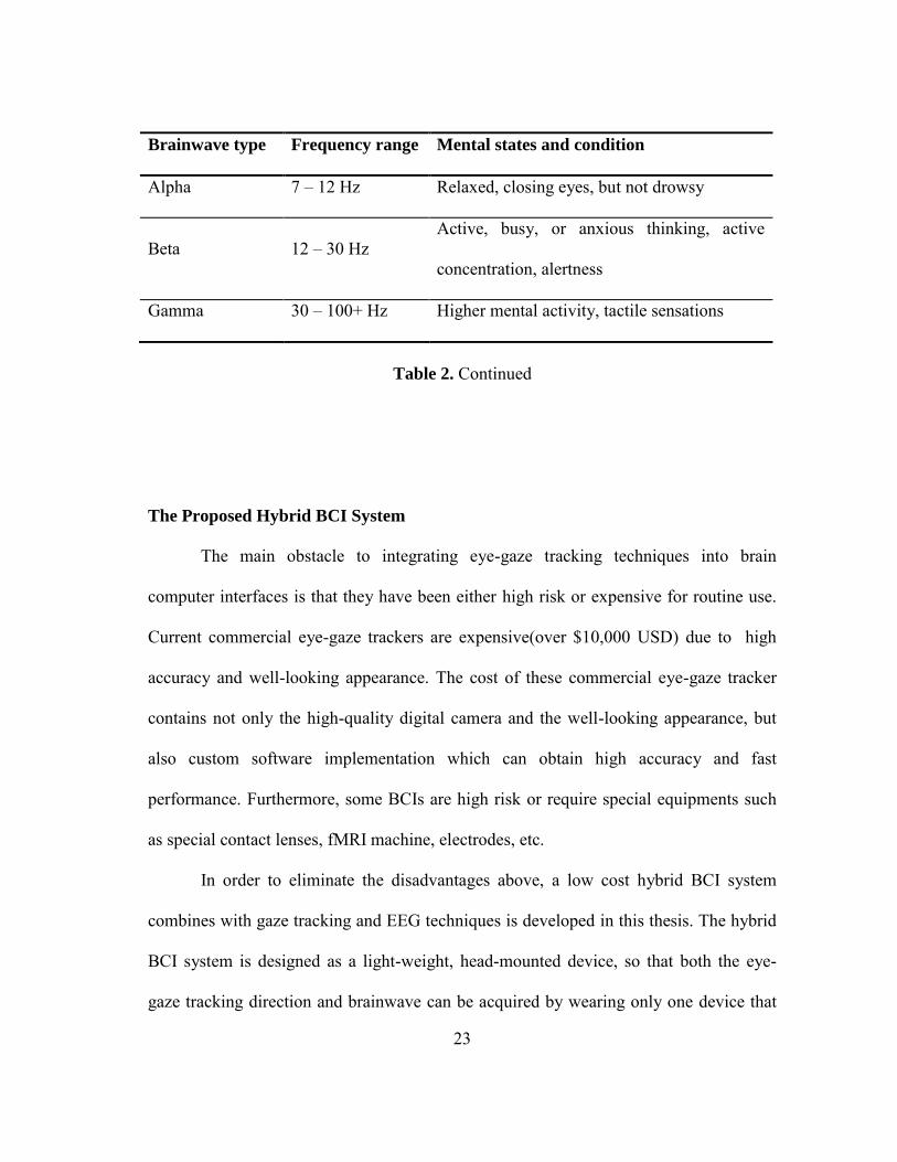
The main obstacle to integrating eye-gaze tracking techniques into brain
computer interfaces is that they have been either high risk or expensive for routine use.
Current commercial eye-gaze trackers are expensive(over $10,000 USD) due to high
accuracy and well-looking appearance. The cost of these commercial eye-gaze tracker
contains not only the high-quality digital camera and the well-looking appearance, but
also custom software implementation which can obtain high accuracy and fast
performance. Furthermore, some BCIs are high risk or require special equipments such
as special contact lenses, fMRI machine, electrodes, etc.
In order to eliminate the disadvantages above, a low cost hybrid BCI system
combines with gaze tracking and EEG techniques is developed in this thesis. The hybrid
BCI system is designed as a light-weight, head-mounted device, so that both the eye-
gaze tracking direction and brainwave can be acquired by wearing only one device that
24
includes one sensing node, an eye camera and a scene camera. A self-build eye-gaze
tracker with two cameras will be introduced in the next two chapters and it only cost less
than $100 USD. The eye-gaze tracking algorithm is developed and programmed in
LabVIEW.
Moreover, NeuroSky MindWave is used for EEG acquisition. When the
NeuroSky MindWave is worn, one electrode will be placed at “ ” based on the
International 10-20 system. The location " " is the most effective locations to
determine concentration and meditation. (Kubota and others 2001, 281-287) Besides,
eye blinking can be detected by EOG in the same location. The NeuroSky MindWave is
sold for $79.99 USD on the market. So the total cost of the hybrid BCI system cost about
$150 USD. It is much cheaper than the commercial eye-gaze trackers and medical EEG
equipments mentioned above. Furthermore, it can achieve 80% performance of
commercial eye-gaze trackers and medical EEG equipments and the cost is just 2% of
them.
25
CHAPTER III
HARDWARE DESIGN
In this thesis, a self-build eye-gaze tracker and a commercial EEG product will
be used. The cost of the eye-gaze tracker includes two cameras and NeuroSky
MindWave are $58.43 USD and $79.99 USD respectively. The total cost of the
hardware in this thesis is $138.42 USD. The design of the eye-gaze tracker and
NeuroSky MindWave is depicted below.
Self-build Eye-gaze Tracker
The eye-gaze tracker is designed for head mounted and mobile use. It works in
infrared spectrum using dark pupil effects. The eye-gaze tracker consists of one camera
for eye tracking, one camera for scene viewing, three IR LED, one 22 ohm resistor, an
IR pass filter and a glasses frame. The construction of the eye-gaze tracker is based on
(Mantiuk and others 2012; Babcock, Pelz, and Peak 2003; Li, Babcock, and Parkhurst
2006, 95-100; Abbott and Faisal 2012, 046016) The materials are listed in Table 3.
The glasses are made of off-the-shelf component. The main part of glasses is the
eye capture module shown as Figure 12A. It is responsible for providing an image of the
eye to the computer. The main part of the module is the circuit inside Microsoft LifeCam
VX-1000 webcam. The Microsoft VX-1000 webcam is disassembled and only the
circuit with camera lens is used. Then we remove the IR filter in the original camera lens
and put a piece of exposed negative film to replace the IR filter. The exposed negative
26
film can be treated as an IR pass filter that allows capturing images in IR light which is
shown in Figure 12A-B. The eye capture module can connect to a computer via USB
port. Based on the USB technical specification an IR illumination system was integrated
with the eye capture module. Three IR LEDs are placed on the capture module and
supplied by USB cable the same as the lens shown as in Figure 12C. This solution is
very practical. The eye capture module is placed at the end of the an aluminum wire and
then mounted to the modified a glasses frame. In the end, the scene camera is placed on
the sensor arm of NeuroSky Mindwave. The complete self-build eye-gaze tracker is
shown in Figure 16.
Part name Quantity Cost
Microsoft LifeCam webcam VX-1000 (for eye tracking) 1 $20
Microsoft LifeCam webcam NX-3000 (for scene) 1 $20
Safety glasses frame 1 $5.95
IR LED 3 $3.76
Carbon resistor 1/4W 22R 1 $0.78
Exposed negative film 20 cm $4.95
Aluminum wire ø 5mm 30 cm $1
Mounting strips 2.4mm x 100mm 3 $0.99
Heat shrinkable tubin ø 10mm 10 cm $1
Total: $58.43
Table 3. Materials of self-build gaze tracker
27
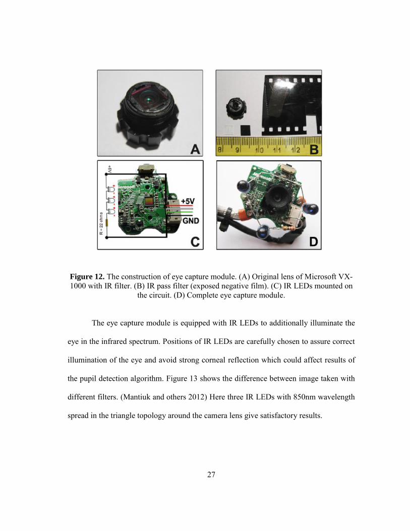
Figure 12. The construction of eye capture module. (A) Original lens of Microsoft VX-1000 with IR filter. (B) IR pass filter (exposed negative film). (C) IR LEDs mounted on
the circuit. (D) Complete eye capture module.
The eye capture module is equipped with IR LEDs to additionally illuminate the
eye in the infrared spectrum. Positions of IR LEDs are carefully chosen to assure correct
illumination of the eye and avoid strong corneal reflection which could affect results of
the pupil detection algorithm. Figure 13 shows the difference between image taken with
different filters. (Mantiuk and others 2012) Here three IR LEDs with 850nm wavelength
spread in the triangle topology around the camera lens give satisfactory results.
28
Figure 13. Image captured by a webcam. (A) With IR filter only. (B) With IR pass filter only. (C) With IR pass filter and illuminate by IR LED. (Mantiuk and others 2012)
NeuroSky MindWave
The NeuruSky MindWave is a single-channel EEG device produced by
Neurosky Inc. The NeuroSky MindWave consists of eight main parts, ear clip, flexible
ear arm, battery area, power switch, adjustable head band, sensor tip, sensor arm and
inside ThinkGear chipset. This device use a dry sensor to measure the EEG signals from
the forehead. The sensor tip is placed at “ ” location based on the International 10-20
system. At the same time, the sensor pick up ambient noise generated by human muscle,
computers, light bulbs, electrical sockets and other electrical devices. This headset
contains NeuroSky ThinkGear technology which measures the analog electrical signals
and processes them into digital signals. The ear clip is a grounds and reference which
allows ThinkGear chip to filter out the electrical noise. Then the chip transmits the
filtered data to a laptop/PC via bluetooth. (Salabun 2014, 169-174) The structure of
MindWave headset is shown in Figure 14.
29
Figure 14. NeuroSky Mindwave headset.
NeuroSky Mindwave can measure raw EEG signals, power spectrum (alpha, beta,
delta, gamma, theta), attention level, mediation level and eye blinking. The raw EEG
data received at a rate of 512 Hz. Other measured values are made every second.
Therefore, raw EEG data is a main source of information on EEG signals using
MindWave.
On the producer webpage, more than 130 applications can be found which is
classified into 4 platforms, 5 genres and 16 developers. These apps do not provide the
source code. Therefore, change of functionality is not possible. However, dynamic-link
library (thinkgear.dll) is available to handle the connection to the device. Moreover, we
can develop our won applications through MATLAB or LabVIEW software. The
30
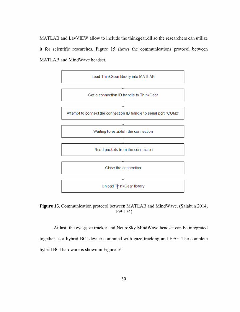
MATLAB and LavVIEW allow to include the thinkgear.dll so the researchers can utilize
it for scientific researches. Figure 15 shows the communications protocol between
MATLAB and MindWave headset.
Figure 15. Communication protocol between MATLAB and MindWave. (Salabun 2014, 169-174)
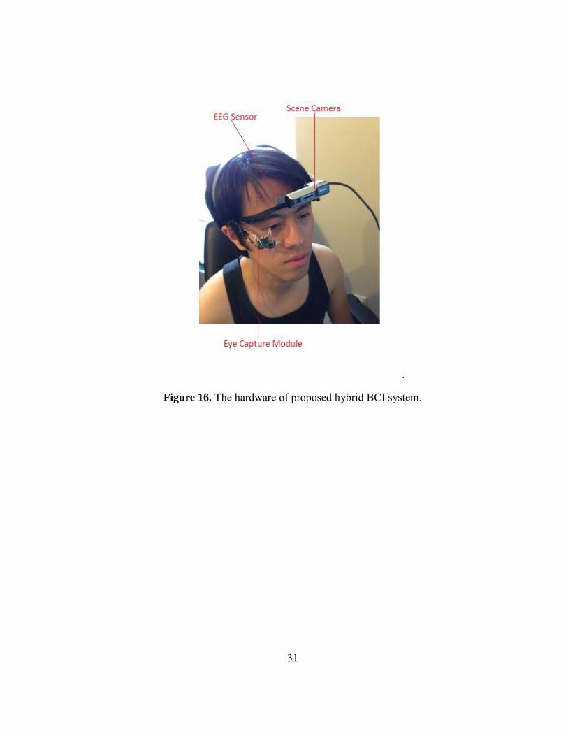
At last, the eye-gaze tracker and NeuroSky MindWave headset can be integrated
together as a hybrid BCI device combined with gaze tracking and EEG. The complete
hybrid BCI hardware is shown in Figure 16.
31
Figure 16. The hardware of proposed hybrid BCI system.
32
CHAPTER IV
SOFTWARE DESIGN
Presented in this chapter are two algorithms both developed in National
Instrument LabVIEW: eye-gaze tracking algorithm and EEG algorithm. The eye-gaze
tracking algorithm developed in the feature-based approach. The objective of this
algorithm is to extract the location of the pupil center so as to map it to the scene image.
The EEG algorithm is designed to detect human's attention level, meditation level and
eye-blinking times. These two algorithms is introduced respectively below.
Eye-gaze Tracking Algorithm
The main goal of eye-gaze tracking algorithm is to locate the pupil center and
project the estimated gaze direction onto the scene image. The eye-gaze tracking can be
divided into two parts: eye feature detection and gaze estimation. Eye feature detection
is to obtain the location of pupil center. Gaze estimation transforms the locations of pupil
center to gaze direction in the scene image through a calibration procedure. A general
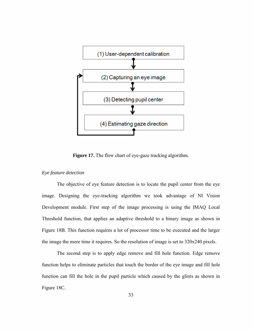
eye-gaze tracking calibration procedure is shown in Figure 17.
33
Figure 17. The flow chart of eye-gaze tracking algorithm.
Eye feature detection
The objective of eye feature detection is to locate the pupil center from the eye
image. Designing the eye-tracking algorithm we took advantage of NI Vision
Development module. First step of the image processing is using the IMAQ Local
Threshold function, that applies an adaptive threshold to a binary image as shown in
Figure 18B. This function requires a lot of processor time to be executed and the larger
the image the more time it requires. So the resolution of image is set to 320x240 pixels.
The second step is to apply edge remove and fill hole function. Edge remove
function helps to eliminate particles that touch the border of the eye image and fill hole
function can fill the hole in the pupil particle which caused by the glints as shown in
Figure 18C.
34
The third step is to apply a particle filter to distinguish the pupil from other dark
particles and estimate its center of mass as shown in Figure 18D. Through the particle
analysis report function, the pupil center can be found in the end shown as in Figure 18E.
Figure 18. Eye feature detection procedure. (A) Original eye image. (B) Convert to a binary image by applying a threshold. (C) Apply edge remove and fill hole function. (D)
Apply a particle filter. (E) The location of pupil center.
Calibration
In order to calculate the point of gaze in the scene image, a mapping must be
constructed between eye-position coordinates and scene-image coordinates. The
mapping can be initialized by relating known eye positions to known scene locations.
The typical procedure in eye-tracking methodology is to measure this relationship
through a calibration procedure. In this thesis, the user is required to look at nine points
of scene image during calibration. Figure 19 shows the mappings between the pupil
movable area defined by the nine pupil centers at calibration procedure and nine
reference points in the scene image. (Lee, Heo, and Park 2013, 10802-10822)
35
Figure 19. Pupil center locations mapping to reference points of scene image.
The pupil movable area constructed by nine pupil center locations can be divided
into four areas as shown in Figure 19. Pupil movable area 1 maps to scene area1, pupil
movable area 2 maps to scene area 2, and so on. For example, pupil movable area 1 is
defined by , , , which maps to scene area 1. And
the mapping function is defined as a transform matrix between pupil movable area 1
and scene area 1 as shown in Figure 20 and 21.
36
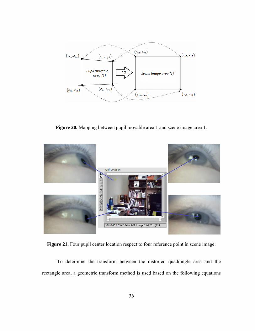
Figure 20. Mapping between pupil movable area 1 and scene image area 1.
Figure 21. Four pupil center location respect to four reference point in scene image.
To determine the transform between the distorted quadrangle area and the
rectangle area, a geometric transform method is used based on the following equations
37
(Gonzalez and Woods 2002; Cho and others 2009a, 127202-127202-15; Lee and others
2010, 289-298):
(3.1)
(3.2)
Equations (3.1) and (3.2) are based on a bilinear approximation which commonly
used in image registration. This geometric transform method can transform a distorted
image into a normal image. As shown in Equation (3.1) and (3.2), the 1st-order
polynomial function includes eight parameters which consider the 2D factor of rotation,
translation, scaling, parallel inclining, and distortion between and . (Lee,
Heo, and Park 2013, 10802-10822) In order to obtain the value of eight unknown
parameters, a transform matrix is represented as follows:
(3.3)
In this thesis, multi-geometric transformations (multiple 1st-order polynomial
functions) with the nine calibration points is used as shown in Figure 19. Four mapping
transforms ( , , and ) are defined between four pupil movable areas and four
scene image areas, as shown in Figure 22.
38
Figure 22. Mapping transforms. (A) Between pupil movable area 1 and scene image area 1. (B) Between pupil movable area 2 and scene image area 2. (C) Between pupil movable area 3 and scene image area 3. (D) Between pupil movable area 1 and scene
image area 1.
As shown in Figure 22A, is the mapping transform matrix between pupil
movable area 1 and scene area 1. Using the training data, the matrix can be obtained
in advance by multiplying and the inverse matrix of in the equation below (Lee,
Heo, and Park 2013, 10802-10822):
(3.4)
39
By applying the same calculation above, transform matrices , and can be
obtained via respective locations of pupil center. Then the gaze point can be estimated
on the scene image via the equation below:
(3.5)
During the tracking stage, if the location of pupil center belongs to the
quadrangle of pupil movable area 1, the matrix in Equation (3.4) is selected and the
gaze point on the scene image is calculated by multiplying and . By the
same method, the pupil center locates in pupil movable area 2, 3 or 4 can be calculated
by multiplying , or and respectively.
Previous studies (Cho and others 2009b, 127202-127202-15; Lee and others
2010, 289-298) also used the 1st-order polynomial function (geometric transform) to
map the pupil movable area onto the screen area. However, the main difference between
the gaze-tracking method in this research and the previous methods is that multi-
geometric transform matrices ( , , and ) is used, whereas previous studies used
only one single geometric transform matrix to map the quadrangle defined by ,
, and into the rectangle defined by , ,
and . Compare with the method in previous studies, multi-geometric
transform matrices method is more robust and accurate.
40
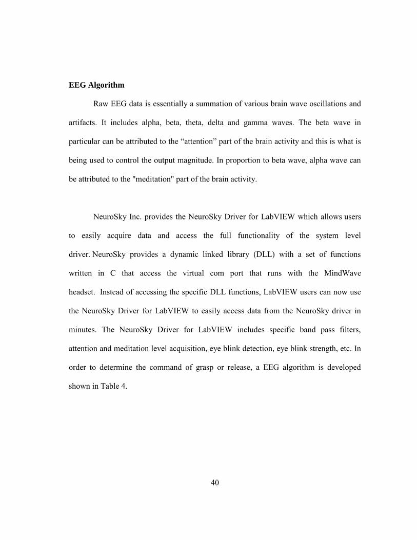
EEG Algorithm
Raw EEG data is essentially a summation of various brain wave oscillations and
artifacts. It includes alpha, beta, theta, delta and gamma waves. The beta wave in
particular can be attributed to the “attention” part of the brain activity and this is what is
being used to control the output magnitude. In proportion to beta wave, alpha wave can
be attributed to the "meditation" part of the brain activity.
NeuroSky Inc. provides the NeuroSky Driver for LabVIEW which allows users
to easily acquire data and access the full functionality of the system level
driver. NeuroSky provides a dynamic linked library (DLL) with a set of functions
written in C that access the virtual com port that runs with the MindWave
headset. Instead of accessing the specific DLL functions, LabVIEW users can now use
the NeuroSky Driver for LabVIEW to easily access data from the NeuroSky driver in
minutes. The NeuroSky Driver for LabVIEW includes specific band pass filters,
attention and meditation level acquisition, eye blink detection, eye blink strength, etc. In
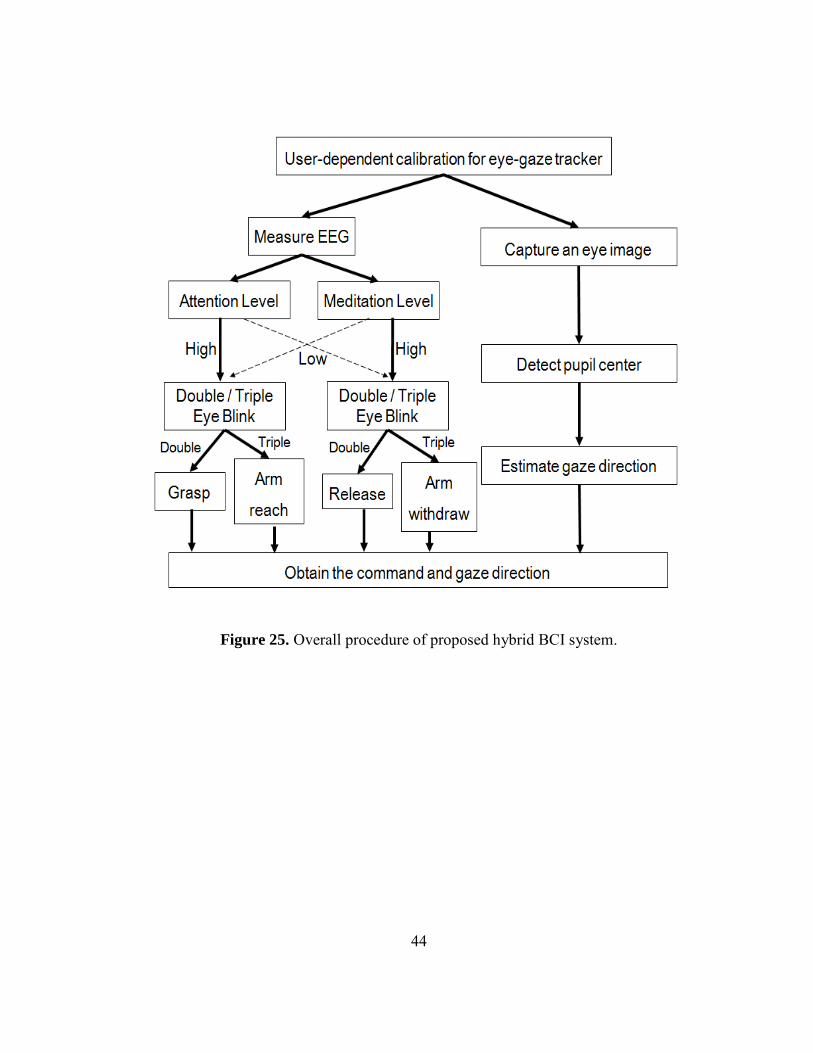
order to determine the command of grasp or release, a EEG algorithm is developed
shown in Table 4.
41
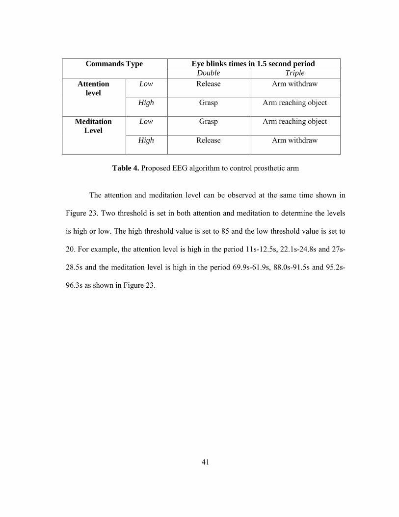
Commands Type Eye blinks times in 1.5 second period
Double Triple
Attention
level
Low Release Arm withdraw
High Grasp Arm reaching object
Meditation
Level Low Grasp Arm reaching object
High Release Arm withdraw
Table 4. Proposed EEG algorithm to control prosthetic arm
The attention and meditation level can be observed at the same time shown in
Figure 23. Two threshold is set in both attention and meditation to determine the levels
is high or low. The high threshold value is set to 85 and the low threshold value is set to
20. For example, the attention level is high in the period 11s-12.5s, 22.1s-24.8s and 27s-
28.5s and the meditation level is high in the period 69.9s-61.9s, 88.0s-91.5s and 95.2s-
96.3s as shown in Figure 23.
42
Figure 23. Attention level and meditation level.
The eye blink is relatively easy to observe from raw EEG signal. The amplitude
of eye blink signal is more larger than the EEG signal shown in Figure 24. A threshold is
set as well to determine there is eye blink or not.
(160,235) and (315,235). After the calculation, four transform matrices , , and
can be obtained. Then we input the values of , , and into the LabVIEW
program to finish the user-dependent calibration.
Before using the NeuroSky MindWave headset, a training procedure is required.
The training procedure helps the NeuroSky MindWave headset to accommodate to user's
brain activity. The user can watch a short training video that helps the user accommodate
to the headset quicker. (Nussbaum and Hargraves 2013) The training procedure usually
takes 10 to 15 minutes. Once the calibration and training procedure are finished, the
program can start to run and the user can start to use the hybrid BCI system. Figure 26
and 27 shows the GUI of eye-gaze tracking and EEG, respectively.
46
Figure 26. GUI of eye-gaze tracking.
Figure 27. GUI of NeuroSky MindWave.
47
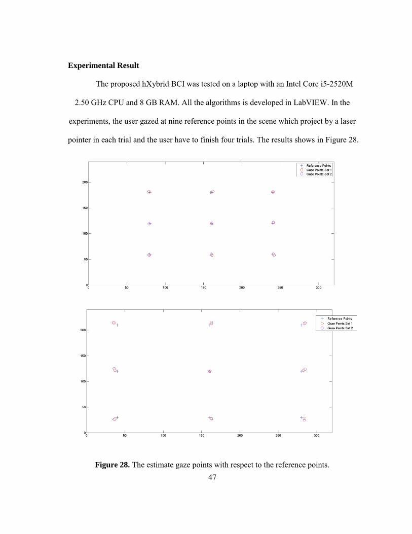
Experimental Result
The proposed hXybrid BCI was tested on a laptop with an Intel Core i5-2520M
2.50 GHz CPU and 8 GB RAM. All the algorithms is developed in LabVIEW. In the
experiments, the user gazed at nine reference points in the scene which project by a laser
pointer in each trial and the user have to finish four trials. The results shows in Figure 28.
Figure 28. The estimate gaze points with respect to the reference points.
48
Conclusion
This thesis has demonstrated the development of a low-cost, light weight, high
performance hybrid brain-computer interface combining eye-gaze tracking and EEG. By
combining these two different BCIs, the human's intention can be captured without using
any muscle. The eye-gaze tracker built with a scene camera can obtain the human gaze
direction, and EEG BCI can measure human's attention and meditation. Based on the
facts, some algorithms can be designed to control intelligent prostheses. The
experimental result shows that the accuracy is good enough to estimate the gaze
direction compared with the expensive commercial eye-gaze trackers. Furthermore, the
cost of the hybrid BCI system is low enough for individual researchers.
In future work, some machine vision algorithms need to be developed in order to
determine the distance between the user and desired reaching object. And error detect
algorithm also needs to be built if the gaze point is not correct on the desired reaching
object.
49
REFERENCES
Abbott, WW and AA Faisal. "Ultra-Low-Cost 3D Gaze Estimation: An Intuitive High Information Throughput Compliment to Direct Brain–machine Interfaces." Journal
of Neural Engineering 9, no. 4 (2012): 046016.
Aftanas, LI and SA Golocheikine. "Human Anterior and Frontal Midline Theta and Lower Alpha Reflect Emotionally Positive State and Internalized Attention: High-Resolution EEG Investigation of Meditation." Neuroscience Letters 310, no. 1 (2001): 57-60.
Babcock, Jason, Jeff Pelz, and Joseph Peak. "The Wearable Eyetracker: A Tool for the Study of High-Level Visual Tasks." In Proceedings of the Military Sensing Symposia
Specialty Group on Camouflage, Concealment, and Deception, Tucson, Arizona. (2003).
Bi, Luzheng, Xin-An Fan, and Yili Liu. "EEG-Based Brain-Controlled Mobile Robots: A Survey." Human-Machine Systems, IEEE Transactions On 43, no. 2 (2013): 161-176.
Carpi, Federico and Danilo De Rossi. "Emg‐ Based and Gaze‐ Tracking‐Based Man–Machine Interfaces." International Review of Neurobiology 86, (2009): 3-21.
Chen, Yingxi and Wyatt S. Newman. "A Human-Robot Interface Based on Electrooculography." In Robotics and Automation, 2004. Proceedings. ICRA'04.
2004 IEEE International Conference on, vol. 1, pp. 243-248. IEEE, 2004.
Cho, Chul Woo, Eui Chul Lee, Kang Ryoung Park, and Ji Woo Lee. "Robust Gaze-Tracking Method by using Frontal-Viewing and Eye-Tracking Cameras." Optical
Engineering 48, no. 12 (2009): 127202-127202.
Drewes, Heiko. "Eye gaze tracking for human computer interaction." PhD diss., Media Informatics Group, LMU Munich, Munich, Germany, 2010.
Gonzalez, Rafael C. and Richard E. Woods. "Digital Image Processing." Prentice-Hall, Upper Saddle River, NJ, USA, 2nd edition. (2002).
Hansen, Dan Witzner, David JC MacKay, John Paulin Hansen, and Mads Nielsen. "Eye Tracking Off the Shelf." In Proceedings of the 2004 symposium on Eye tracking
research & applications, pp. 58-58. ACM, 2004.
Khalid, Muhammad Bilal, Naveed Iqbal Rao, Intisar Rizwan-i-Haque, Sarmad Munir, and Farhan Tahir. "Towards a Brain Computer Interface using Wavelet Transform
50
with Averaged and Time Segmented Adapted Wavelets." In Computer, Control and
Communication, 2009. IC4 2009. 2nd International Conference on, pp. 1-4. IEEE, 2009.
Kübler, Andrea, Boris Kotchoubey, Jochen Kaiser, Jonathan R. Wolpaw, and Niels Birbaumer. "Brain–computer Communication: Unlocking the Locked in." Psychological Bulletin 127, no. 3 (2001): 358.
Kubota, Yasutaka, Wataru Sato, Motomi Toichi, Toshiya Murai, Takashi Okada, Akiko Hayashi, and Akira Sengoku. "Frontal Midline Theta Rhythm is Correlated with Cardiac Autonomic Activities during the Performance of an Attention Demanding Meditation Procedure." Cognitive Brain Research 11, no. 2 (2001): 281-287.
Lee, Eui Chul, Jin Cheol Woo, Jong Hwa Kim, Mincheol Whang, and Kang Ryoung Park. "A Brain–computer Interface Method Combined with Eye Tracking for 3D Interaction." Journal of Neuroscience Methods 190, no. 2 (2010): 289-298.
Lee, Ji Woo, Hwan Heo, and Kang Ryoung Park. "A Novel Gaze Tracking Method Based on the Generation of Virtual Calibration Points." Sensors 13, no. 8 (2013): 10802-10822.
Lee, Kwang-Hyuk, Leanne M. Williams, Michael Breakspear, and Evian Gordon. "Synchronous Gamma Activity: A Review and Contribution to an Integrative Neuroscience Model of Schizophrenia." Brain Research Reviews 41, no. 1 (2003): 57-78.
Li, Dongheng. "Low-cost eye-tracking for human computer interaction." MS thesis, Iowa State University, Ames, IA, USA, 2006.
Li, Dongheng, Jason Babcock, and Derrick J. Parkhurst. "openEyes: A Low-Cost Head-Mounted Eye-Tracking Solution." In Proceedings of the 2006 symposium on Eye
tracking research & applications, pp. 95-100. ACM, 2006.
Malmivuo, Jaakko and Robert Plonsey. Bioelectromagnetism: Principles and
Applications of Bioelectric and Biomagnetic Fields. Oxford, U.K.: Oxford University Press, 1995.
Mantiuk, Radosław, Michał Kowalik, Adam Nowosielski, and Bartosz Bazyluk. "Do-it-Yourself Eye Tracker: Low-Cost Pupil-Based Eye Tracker for Computer Graphics Applications." In Advances in Multimedia Modeling. K. Schoeffmann, et al., Eds. Berlin/Heidelberg, Germany: Springer, 2012, pp. 115-125.
51
Morimoto, Carlos H. and Marcio RM Mimica. "Eye Gaze Tracking Techniques for Interactive Applications." Computer Vision and Image Understanding 98, no. 1 (2005): 4-24.
Morimoto, Carlos Hitoshi, David Koons, Arnon Amir, and Myron Flickner. "Pupil Detection and Tracking using Multiple Light Sources." Image and Vision Computing 18, no. 4 (2000): 331-335.
Nicolas-Alonso, Luis Fernando and Jaime Gomez-Gil. "Brain Computer Interfaces, a Review." Sensors 12, no. 2 (2012): 1211-1279.
Nussbaum, Paul Alton and Rosalyn Hobson Hargraves. "Pilot Study: The use of Electroencephalogram to Measure Attentiveness Towards Short Training Videos." International Journal of Advanced Computer Science & Applications 4, no. 3 (2013).
Pfurtscheller, Gert, Brendan Z. Allison, Clemens Brunner, Gunther Bauernfeind, Teodoro Solis-Escalante, Reinhold Scherer, Thorsten O. Zander, Gernot Mueller-Putz, Christa Neuper, and Niels Birbaumer. "The Hybrid BCI." Frontiers in
Neuroscience 4, (2010).
Pfurtscheller, Gert and Christa Neuper. "Motor Imagery and Direct Brain-Computer Communication." Proceedings of the IEEE 89, no. 7 (2001): 1123-1134.
Pineda, Jaime A. "The Functional Significance of Mu Rhythms: Translating “seeing” and “hearing” into “doing”." Brain Research Reviews 50, no. 1 (2005): 57-68.
Salabun, Wojciech. "Processing and Spectral Analysis of the Raw EEG Signal from the MindWave." Przeglad Elektrotechniczny 90, (2014): 169-174.
Schalk, Gerwin, Dennis J. McFarland, Thilo Hinterberger, Niels Birbaumer, and Jonathan R. Wolpaw. "BCI2000: A General-Purpose Brain-Computer Interface (BCI) System." Biomedical Engineering, IEEE Transactions On 51, no. 6 (2004): 1034-1043.
Wolpaw, Jonathan R., Niels Birbaumer, Dennis J. McFarland, Gert Pfurtscheller, and Theresa M. Vaughan. "Brain–computer Interfaces for Communication and Control." Clinical Neurophysiology 113, no. 6 (2002): 767-791.
Zhang, Biao, Jianjun Wang, and Thomas Fuhlbrigge. "A Review of the Commercial Brain-Computer Interface Technology from Perspective of Industrial Robotics." In Automation and Logistics (ICAL), 2010 IEEE International Conference on, pp. 379-384. IEEE, 2010.
52
Zhang, Li, Wei He, Chuanhong He, and Ping Wang. "Improving Mental Task Classification by Adding High Frequency Band Information." Journal of Medical
Systems 34, no. 1 (2010): 51-60.
Zielinski, P. "Opengazer: Open-Source Gaze Tracker for Ordinary Webcams." Samsung