A hybrid force model to estimate the dynamics of curved legs in granular material Lichao Xu, Shiwu Zhang ⇑ , Nan Jiang, Ronald Xu Dept. of Precision Machinery and Precision Instrumentation, University of Science and Technology of China, Hefei, Anhui 230026, China Received 25 August 2014; received in revised form 24 March 2015; accepted 26 March 2015 Available 11 April 2015 Abstract Robot locomotion on rigid terrain or in fluids has been studied to a large extent. The locomotion dynamics on or within soft sub- strates such as granular material (GM) has not been fully investigated. This paper proposes a hybrid force model to simulate and evalu- ate the locomotion performance of a legged terrestrial robot in GM. The model incorporates an improved Resistive Force Theory (RFT) model and a failure-based model. The improved RFT model integrates the force components of individual leg elements over the curved leg portion submerged in GM at any moment during a full period of leg rotation. The failure-based model is applied in a bar drag model to yield the normal and the lateral forces of the individual RFT elements as functions of the locomotion depth and speed. The hybrid model is verified by the coincidence between the theoretical predictions and the experimental results. The hybrid model is used to analyze the effects of angular velocity and leg shape with high precision and can guide the design of the legs with any profiles. Our study reveals that the interactions between locomotor and substrate are determined by the locomotor structural characteristics, the nature of the sub- strate, and the control strategy. Ó 2015 ISTVS. Published by Elsevier Ltd. All rights reserved. Keywords: Terrestrial robots; Locomotion; Hybrid force model; Dynamics; Granular material 1. Introduction Developing robots able to overcome complex environ- ments has aroused more and more interests. A number of research groups have done excellent work on exploring robot locomotion in solid, liquid, and the transitional environments (Saranli et al., 2001; Raibert et al., 2008; Crespi et al., 2013; Boxerbaum et al., 2005; Dudek et al., 2007). Understanding dynamics of locomotors in soft sub- strates is significant to improve the locomotory perfor- mance of the robots in terrains such as desert and beach. Generally, there are two methods to explore the interaction between robots and terrains. One is through semiempirical equations based on well-known pressure-sinkage model (Bekker, 1969) and shearing stress-displacement model (Janosi and Hanamoto, 1961), which has been widely used in design of locomotors and soil mechanics prediction (Asnani et al., 2009; Ding et al., 2013; Iagnemma et al., 2004; Ding et al., 2013; Patel et al., 2004). The other method is mainly through FEM or DEM simulation based on different contact models (Xia, 2011; Fervers, 2004; Smith and Peng, 2013), these works also promoted the in-depth understanding of material properties and their interaction with robots. However, the limitation of the existing models generally cannot be applied when the locomotors semi-submerge in loose terrain (Terzaghi, 1943), and the parameters in simulation model have to be carefully adjusted to reflect the practical situation. Con- sidering this, robot locomotion in granular materials (GMs) is still in need of extensively study. Compared with solid and liquid materials, GMs show elastic deformation http://dx.doi.org/10.1016/j.jterra.2015.03.005 0022-4898/Ó 2015 ISTVS. Published by Elsevier Ltd. All rights reserved. ⇑ Corresponding author. E-mail address: [email protected](S. Zhang). www.elsevier.com/locate/jterra Available online at www.sciencedirect.com ScienceDirect Journal of Terramechanics 59 (2015) 59–70 Journal of Terramechanics
Transcript
Available online at www.sciencedirect.com
Journal
www.elsevier.com/locate/jterra
ScienceDirect
Journal of Terramechanics 59 (2015) 59–70
ofTerramechanics
A hybrid force model to estimate the dynamics of curved legsin granular material
Lichao Xu, Shiwu Zhang ⇑, Nan Jiang, Ronald Xu
Dept. of Precision Machinery and Precision Instrumentation, University of Science and Technology of China, Hefei, Anhui 230026, China
Received 25 August 2014; received in revised form 24 March 2015; accepted 26 March 2015Available 11 April 2015
Abstract
Robot locomotion on rigid terrain or in fluids has been studied to a large extent. The locomotion dynamics on or within soft sub-strates such as granular material (GM) has not been fully investigated. This paper proposes a hybrid force model to simulate and evalu-ate the locomotion performance of a legged terrestrial robot in GM. The model incorporates an improved Resistive Force Theory (RFT)model and a failure-based model. The improved RFT model integrates the force components of individual leg elements over the curvedleg portion submerged in GM at any moment during a full period of leg rotation. The failure-based model is applied in a bar drag modelto yield the normal and the lateral forces of the individual RFT elements as functions of the locomotion depth and speed. The hybridmodel is verified by the coincidence between the theoretical predictions and the experimental results. The hybrid model is used to analyzethe effects of angular velocity and leg shape with high precision and can guide the design of the legs with any profiles. Our study revealsthat the interactions between locomotor and substrate are determined by the locomotor structural characteristics, the nature of the sub-strate, and the control strategy.� 2015 ISTVS. Published by Elsevier Ltd. All rights reserved.
Keywords: Terrestrial robots; Locomotion; Hybrid force model; Dynamics; Granular material
1. Introduction
Developing robots able to overcome complex environ-ments has aroused more and more interests. A number ofresearch groups have done excellent work on exploringrobot locomotion in solid, liquid, and the transitionalenvironments (Saranli et al., 2001; Raibert et al., 2008;Crespi et al., 2013; Boxerbaum et al., 2005; Dudek et al.,2007). Understanding dynamics of locomotors in soft sub-strates is significant to improve the locomotory perfor-mance of the robots in terrains such as desert and beach.Generally, there are two methods to explore the interactionbetween robots and terrains. One is through semiempiricalequations based on well-known pressure-sinkage model
http://dx.doi.org/10.1016/j.jterra.2015.03.005
0022-4898/� 2015 ISTVS. Published by Elsevier Ltd. All rights reserved.
⇑ Corresponding author.E-mail address: [email protected] (S. Zhang).
(Bekker, 1969) and shearing stress-displacement model(Janosi and Hanamoto, 1961), which has been widely usedin design of locomotors and soil mechanics prediction(Asnani et al., 2009; Ding et al., 2013; Iagnemma et al.,2004; Ding et al., 2013; Patel et al., 2004). The othermethod is mainly through FEM or DEM simulation basedon different contact models (Xia, 2011; Fervers, 2004;Smith and Peng, 2013), these works also promoted thein-depth understanding of material properties and theirinteraction with robots. However, the limitation of theexisting models generally cannot be applied when thelocomotors semi-submerge in loose terrain (Terzaghi,1943), and the parameters in simulation model have to becarefully adjusted to reflect the practical situation. Con-sidering this, robot locomotion in granular materials(GMs) is still in need of extensively study. Compared withsolid and liquid materials, GMs show elastic deformation
r normal stress (Pa)s tangential stress (Pa)Ff forward advancing force (N)Fs supportive force (N)T torque (N m)c density of GM (g/cm3)h height of the fixed motor axle (cm)h1 depth of bar (cm)h0 width of bar (cm)Ls subsurface part length of curved leg (cm)b angle of direction of F\(�)Fz lift force on the bar (N)n angular position of element (rad)d submerging depth of element (cm)x angular velocity of the leg (rad/s)v speed vector of element/bar (rad/s)F\ normal force component (N)
Fk tangential force component (N)C\ maximum F\ (N)Ck maximum Fk (N)W1, W2 weight of GM in active/passive failure state (N)a, b axis of elliptical legs/, /w friction angle within sand/between sand and bar
(rad)r distance from element to rotating axle (mm)Mx, My torque caused by dFf and dFs (N m)a1, a2 angle between active/passive failure plane and x
-axis negative direction (rad)X1, X2 forces among sands in various states (N)P, Pw force between bar and sands in passive failure
region/force on sands in active failure region (N)k, k coefficient for variation of GM bulk density (-)w angle from v to tangential direction of element
(�)
60 L. Xu et al. / Journal of Terramechanics 59 (2015) 59–70
below the yield limit and different rheological propertieswhen destructed (Terzaghi, 1943; Kadanoff, 1999).
Some researchers have revealed GMs failure characteris-tics as well as the dynamics of intruders of regular shapemoving in GMs. For example, Nedderman described thestatics and the kinematics of GMs in a container(Nedderman, 2005); Albert et al. studied the forces appliedto a cylinder as it was dragged in a GM at a low speed(Albert et al., 1999); Camorra et al. analyzed the projectileimpact for improved calibration in particle dynamics sim-ulation (Ciamarra et al., 2004). Recently, Maladen et al.proposed the “Resistive Force Theory” (RFT) to modelthe undulatory swimming of a sandfish lizard (Goldmanet al., 2009). Despite these efforts, it is still difficult to esti-mate the interaction forces between the locomotion mecha-nisms and the substrate, which is crucial for the locomotionperformance of desert robots, amphibious robots or plane-tary robots in GM environments (Goldman et al., 2009;Liang et al., 2012; Knuth et al., 2012; Zhang et al., 2013;Gao et al., 2012). One obstacle is that the locomotion ofthe robot legs with complex shapes in GM involves varyingintruding depths and directions that can hardly calculatedthrough a limited number of experiments.
In this paper, a hybrid force model that incorporates animproved RFT model and a failure-based model is pro-posed to explore the leg–GM interaction with a relativelyhigh precision. The failure-based model calculates theforces on a dragged bar within GM at a low speed. Withminor modifications, it can also be applied to move withinGM at a high speed. By combining the failure-based modelwith an improved RFT model, one can conveniently esti-mate the forces applied to the locomotors as they penetratein GM. The proposed hybrid model needs only a limitednumber of parameters that are readily measurable, as evi-denced by our experiments. It is also observed that the
angular velocity contributes negligibly to the leg–GMinteraction within a certain working range. With such sim-plification, the forces and torques applied to different typesof semi-elliptical legs are calculated in order to reveal theperformance dependence of robot locomotion and guidethe leg shape design. A major advantage of the proposedmodel is that it considers the macroscopic effect of forcechains in the GM environment without the need to includethe complicated microscopic parameters, such as the orig-ination and the transmission of the forces among granularparticles. In summary, this study forms the basis for leg–GM interaction analysis and may further guide the designof the robot legs for optimal locomotion performance in aGM environment.
2. Materials and methods
The locomotion performance of a terrestrial robot isdetermined by the propulsion modes associated with thestructure of the locomotors. Two common types oflocomotion structures are wheels and legs. As a popularman-made locomotion mechanism, the wheel is designedto accomplish many daily tasks on even terrain, and thewheel–soil interaction has been extensively studied(Asnani et al., 2009; Ding et al., 2013; Iagnemma et al.,2004; Senatore et al., 2013). Legged robots or humanbeings are able to adapt to rough terrain, and the leg-terrain dynamics is usually analyzed with an inverted pen-dulum model. Furthermore, the dynamics between straightlegs and GMs are also explored with various experimentsand simulations (Ding et al., 2013; Liu and Kushwaha,2010; Yeomans et al., 2013; Scott and Saaj, 2012). As pre-sented by the previous study, both of these two locomotionstructures suffer the performance lost in GMs (Lejeuneet al., 1998).
L. Xu et al. / Journal of Terramechanics 59 (2015) 59–70 61
2.1. Locomotion mechanisms in GM
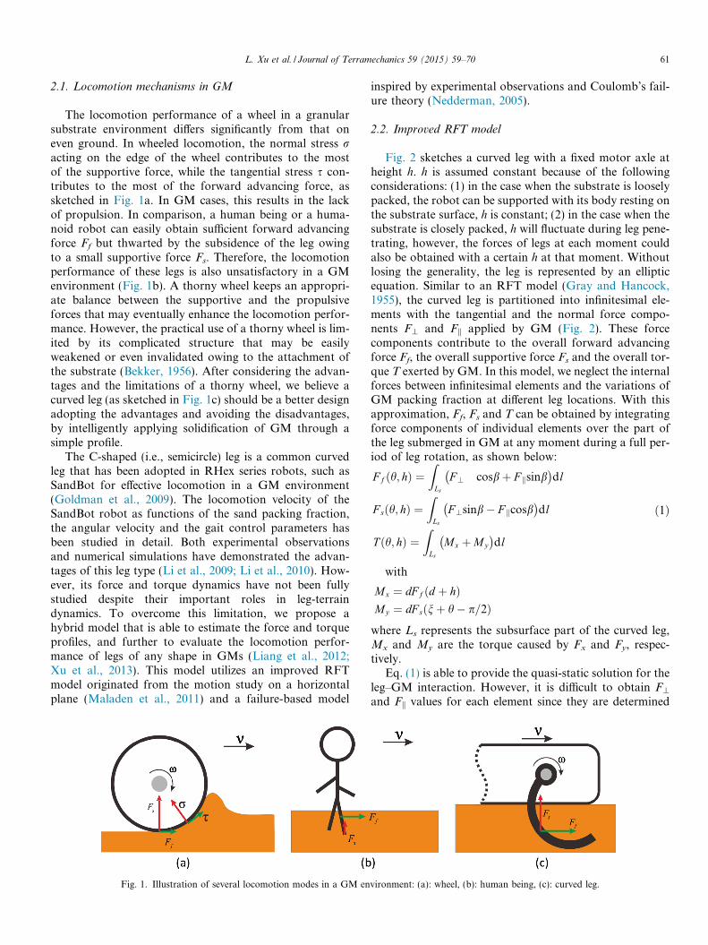
The locomotion performance of a wheel in a granularsubstrate environment differs significantly from that oneven ground. In wheeled locomotion, the normal stress racting on the edge of the wheel contributes to the mostof the supportive force, while the tangential stress s con-tributes to the most of the forward advancing force, assketched in Fig. 1a. In GM cases, this results in the lackof propulsion. In comparison, a human being or a huma-noid robot can easily obtain sufficient forward advancingforce Ff but thwarted by the subsidence of the leg owingto a small supportive force Fs. Therefore, the locomotionperformance of these legs is also unsatisfactory in a GMenvironment (Fig. 1b). A thorny wheel keeps an appropri-ate balance between the supportive and the propulsiveforces that may eventually enhance the locomotion perfor-mance. However, the practical use of a thorny wheel is lim-ited by its complicated structure that may be easilyweakened or even invalidated owing to the attachment ofthe substrate (Bekker, 1956). After considering the advan-tages and the limitations of a thorny wheel, we believe acurved leg (as sketched in Fig. 1c) should be a better designadopting the advantages and avoiding the disadvantages,by intelligently applying solidification of GM through asimple profile.
The C-shaped (i.e., semicircle) leg is a common curvedleg that has been adopted in RHex series robots, such asSandBot for effective locomotion in a GM environment(Goldman et al., 2009). The locomotion velocity of theSandBot robot as functions of the sand packing fraction,the angular velocity and the gait control parameters hasbeen studied in detail. Both experimental observationsand numerical simulations have demonstrated the advan-tages of this leg type (Li et al., 2009; Li et al., 2010). How-ever, its force and torque dynamics have not been fullystudied despite their important roles in leg-terraindynamics. To overcome this limitation, we propose ahybrid model that is able to estimate the force and torqueprofiles, and further to evaluate the locomotion perfor-mance of legs of any shape in GMs (Liang et al., 2012;Xu et al., 2013). This model utilizes an improved RFTmodel originated from the motion study on a horizontalplane (Maladen et al., 2011) and a failure-based model
Fig. 1. Illustration of several locomotion modes in a GM en
inspired by experimental observations and Coulomb’s fail-ure theory (Nedderman, 2005).
2.2. Improved RFT model
Fig. 2 sketches a curved leg with a fixed motor axle atheight h. h is assumed constant because of the followingconsiderations: (1) in the case when the substrate is looselypacked, the robot can be supported with its body resting onthe substrate surface, h is constant; (2) in the case when thesubstrate is closely packed, h will fluctuate during leg pene-trating, however, the forces of legs at each moment couldalso be obtained with a certain h at that moment. Withoutlosing the generality, the leg is represented by an ellipticequation. Similar to an RFT model (Gray and Hancock,1955), the curved leg is partitioned into infinitesimal ele-ments with the tangential and the normal force compo-nents F\ and Fk applied by GM (Fig. 2). These forcecomponents contribute to the overall forward advancingforce Ff, the overall supportive force Fs and the overall tor-que T exerted by GM. In this model, we neglect the internalforces between infinitesimal elements and the variations ofGM packing fraction at different leg locations. With thisapproximation, Ff, Fs and T can be obtained by integratingforce components of individual elements over the part ofthe leg submerged in GM at any moment during a full per-iod of leg rotation, as shown below:
F f ðh; hÞ ¼Z
Ls
F ? cosbþ F ksinb� �
dl
F sðh; hÞ ¼Z
Ls
F ?sinb� F kcosb� �
dl
T ðh; hÞ ¼Z
Ls
Mx þMy
� �dl
ð1Þ
with
Mx ¼ dF f ðd þ hÞMy ¼ dF sðnþ h� p=2Þ
where Ls represents the subsurface part of the curved leg,Mx and My are the torque caused by Fx and Fy, respec-tively.
Eq. (1) is able to provide the quasi-static solution for theleg–GM interaction. However, it is difficult to obtain F\
and Fk values for each element since they are determined
vironment: (a): wheel, (b): human being, (c): curved leg.
Fig. 2. Schematic of RFT analysis for a semi-elliptical leg penetrating GMat a certain depth. h is the height of the rotation axle above the surface ofGM. d is the depth of the element, dl, from GM surface, n denotes theangular position of the element. a and b are the long axial radius and theshort axis radius of the elliptical leg, respectively. h denotes the position ofthe curved leg, which is defined as the angle from the long axle of theelliptical leg to the positive direction along y-axis. F\ and Fk are the forcesin the tangential direction of the elliptic at the element and thecorresponding normal direction, respectively. dFf and dFs represent theforces resolved into x-axis direction and y-axis direction respectively. xrepresents the angular velocity of the leg. m denotes the speed vector of theelement, while w denotes the angle between m and the tangential directionof the element. b denotes the angle between F\ and dFf, r denotes thedistance from the element to the rotating axle.
62 L. Xu et al. / Journal of Terramechanics 59 (2015) 59–70
by many coupled parameters such as the GM characteris-tics, the submerging depth of the element, the velocity ofthe element, and the tangential direction of the ellipticalcurve at the designated position. Previous studies haveexamined the drag force applied on a submerged rod thatmoves horizontally (Kadanoff, 1999; Albert et al., 2000),the forces applied on an inclined plow or a lug duringmovement in GMs (Yang et al., 2014; Percier et al.,2011), as well as the effect of the locomotor geometry onthe resultant forces (Ding et al., 2011). However, no gen-eral theory has been established to explain the complicatedlocomotion dynamics that involves variable penetrationdepths and directions of the moving elements. We proposean improved RFT model to simulate locomotion dynamicsof a curved leg in GM. It is assumed that the forces appliedon each element are only relevant to its projected area onthe plane perpendicular to its instantaneous velocity direc-tion, velocity magnitude, and depth d. This assumption isbased on the analogy between GMs and a low Re fluidin the force origin (Gray and Hancock, 1955; Metcalfeet al., 2002; Lighthill, 1969). With the assumption, theforces F\ and Fk can be expressed as following:
F ? ¼ f 1ðw; t; dÞ ¼ f 1ðh; n;xÞF k ¼ f 2ðw; t; dÞ ¼ f 2ðh; n;xÞ
ð2Þ
Noted that the forces applied to each element are inte-grated only when w > 0, as it represents the situation wherethe moving element is in contact with GM. When w < 0,the element moves toward the space where the GM hasbeen pushed away by the curved leg in the previous posi-
tion. To obtain Ff, Fs, and T, a trapezoidal-cross-sectionbar is dragged horizontally in GM to mimic the situationin a RFT model and the forces perpendicular and parallelto the longitudinal direction of the bar are recordedexperimentally.
2.3. Bar drag experiment
An experimental setup as shown in Fig. 3a is used forforce recording in locomotion dynamic analysis. A bar issubmerged in GM at a specific depth and dragged by a slid-ing table fixed to a synchronous belt. The belt is driven by astepping motor at a constant speed in the range of1–100 cm/s. The angle between the longitudinal directionof the bar and the dragging direction can be convenientlyadjusted by a dividing plate beneath the sliding table. Asix-dimensional force sensor is mounted between the divid-ing plate and a vertical rod that is connected to the bar torecord the forces exerted on the bar while dragging in drysand. The sand used in the experiment is obtained fromriver banks that mixed three types of sand at a mixing ratioof 6:5:1. These sand samples are with particle diameters(PDs) of about 0.56 mm, 0.28 mm, and 0.125 mm, respec-tively. The average particle diameter (APD) is about0.41 mm and the bulk density (the ratio of the mass andthe volume, c) is 1.3454 g/cm3. The experiment is carriedout in a glass tank of 1100 cm � 50 cm � 30 cm (i.e.,2683 APD � 1220 APD � 732 APD), which is largeenough to eliminate the boundary effect of the tank onexperimental result. The sand particles filled the tank arefully combed and flattened in order to maintain the samec before each measurement. The bar is designed to have atrapezoidal cross section, with its length 10 times greaterthan its width. This design simplifies the force estimationon the stress surface by subtracting the forces on two endsurfaces of the bar and neglecting the forces applied onthe upper and the lower inclined surfaces (Lee andHerrmann, 1999).
As shown in Fig. 3b, the forces are recorded at differenttest conditions during the bar dragged in the GM. Themeasured forces demonstrate periodic fluctuations due tothe elastic compression of sand below the critical failurepoint and the rapid destruction of sand above it. Thesefluctuating forces are averaged within a specific windowin order to study the correlation of the forces with respectto the dragging angle and depth (Fig. 3d and e). In theexperiment, the lift force in the z-axis direction Fz, the forcenormal to the stress surface F\, and the force along thestress surface Fk (Fig. 3B) were measured with various w,which is set as an array with 4.5� interval in the range of0�–90�. Fz caused by drag in horizontal direction wasobserved at different w, and increased with the increase ofw (Fig. 3c), which was also analyzed in Ding et al.(2011), and this inspired the establishment of our failure-based model, which will be discussed in detail bellow. F\
presents an upward trend in the entire range, for the barneeded to push away more sand blocking its way as w
(a)
(b)
(c)
x
yz
(d)
(e)
Fig. 3. Bar drag experiment performed to predict the forces on the element in Eq. (2). (a): Schematic of the experimental setup, v is the velocity of the bar.F\ and Fk represent the normal force and the tangential force on the bar, respectively. Angle w between Fk and v is adjustable with a 4.5� resolution. Fz
denotes the lift force caused by horizontal drag. (b): An example of the bar dragged in the GM. (c): Average Fz measured at different w at depth of 2 cm.(d): F\ and (e): Fkmeasured in the experiment with respect to w at depth of 2 cm, 3 cm, 4 cm. Dashed lines are model fits described by Eqs. (3) and (4). Thebar was dragged at a constant speed of 1 cm/s. Due to the influence of connecting cylinder at the back of the bar, the data recorded at w = 0� and w = 4.5�are biased.
L. Xu et al. / Journal of Terramechanics 59 (2015) 59–70 63
increased (Fig. 3d). The situation of Fk is relatively com-plex (Fig. 3e), which is affected by the sands on the frontof the bar and F\. The flow of the sands on the front ofthe bar becomes few that decrease Fk as w increases; whilethe increase of F\ will raises Fk by increasing friction. InRegion I (w is less than 36�), Fk increases slowly for thedominant influence of F\, however, afterward, it decreasesmore rapidly for the dominant influence of sand flows,which offsets the impact brought by F\ and finally deter-mines its zero value when w equals 90� (Region II). Withthe bar drag experiment, the forces on the bar with variousw at certain depths can be obtained. Then, the key is thatthe trends of F\ and Fk are applicable at the conditionsof any depth and any speed.
Based on the above analysis, we developed an empiricalfitting model describes the relationship between the forcesand angle w. F\ on the bar (excluding two end surfaces)can be written as
F ? ¼ Ch? þ C? � Ch
?� �
sin w ð3Þ
Fk in Region I and II can be respectively approximatedas
F Ik ¼ Ch
k þ Ck � Chk
� �sin w
F IIk ¼ Ck cos w
ð4Þ
where Ch? and Ch
k, describes depth dependent components
in F\ and Fk at w = 0�, respectively. C\ and Ck representthe maximum F\ and Fk can reach, which occur at
w = 90� and w = 36� in our experiment, respectively. Wefound that there exists a nearly constant ratio between Ckand C\, which equals 0.37 ± 0.02 through a lot of experi-ments. Considering C\’s important role in the deter-mination of the curves, and the value of C\ varies alongwith the depth of the bar, we adopted a failure-basedmodel to obtain them.
2.4. Failure-based model
Here we propose a failure-based model to obtain F\
when w equals 90� at various depths. When w equals 90�,theoretically, Fk should be zero, while F\ should reach itsmaximum for the bar pushes the most amount of sandblocking its way in the situation. Taking into account ofsand forced movement in bar drag experiment, the top sur-face of sand bulging in front of the bar and then subsiding,a failure-based model was proposed. As shown in Fig. 4,the GM surrounding the bar is divided into two regions.For the sand in triangular region (ABC), just in upper frontof the bar, it subsides quickly, filling the space caused bythe movement of the bar, and can be regarded in activefailure state, while the sand in trapezoidal region (ACDE)contributes to the bulge can be regarded in passive failurestate (Ciamarra et al., 2004).
Assuming unit-distance in z direction, W1 and W2 canbe expressed as
W 1 ¼c2
h21cota1; W 2 ¼
c2ðh0 þ h1Þ2cota2 � h2
1cota1
� �ð5Þ
Fig. 4. A failure-based model to calculate F\. W1 and W2 are the weight of GM in active failure and passive failure state, respectively. P denotes the forcebetween sands in region ABC and outside, while Pw denotes force between the bar and sands in region ACDE. X1 and X2 represent the forces betweensands in regions ABC and ACDE, and sands in region ACDE and below, respectively. / is the friction angle within sand and /w is the friction anglebetween sand and the bar, which can all be measured by shear tests. h1 denotes the distance between the surface of the sand and the top edge of the bar. h0
represents the width of the bar. AC and DE represent the active failure plane and passive failure plane, respectively, a1 and a2 represent the angles betweenthe active and passive failure plane and x-axis negative direction, respectively.
0 90αmin αmax
Angle (degree)
Forc
e (N
)
Passive failure
Stable zoneActive failure
Fig. 5. Force in active failure zone, passive failure zone, and stable zone ofGM.
64 L. Xu et al. / Journal of Terramechanics 59 (2015) 59–70
Assuming that the bar is dragged in a low speed, i.e. theactive failure region and the passive failure are in quasi-sta-tic state, the equilibrium equation of the forces for theactive failure region can be resolved horizontally andvertically
X 2 cosða2 þ /Þ � X 1 cosða1 � /Þ � P w sin /w ¼ W 2 ð9Þ
Solving Eq. (9), gives
P w ¼W 2 sinða2 þ /Þ þ X 1 sinða2 � a1 þ 2/Þ½ �
cos /w þ a2 þ /ð Þ ð10Þ
The change curve of P in the state of active failure isdepicted as blue solid line in Fig. 5. Without disturbance,P locates in stable zone. Once the bar is dragged, P
decreases toward Pmax to reach active failure zone, atwhich P reaches Pmax when a1 equals amax. The changecurve of Pw in the state of passive failure is depicted as
red dashdot line in Fig. 5. Without disturbance, Pw alsolocates in stable zone. When the bar is dragged, Pw
increases toward Pmin to reach passive failure zone, whichresult in failures in different planes. Combined with thecharacteristics of the curves of both failures, motion canbe considered to occur at the critical points in the sametime roughly, thus P reaches Pmax when a1 equals amax
and Pw reaches Pmin when a2 equals amin, if the bar isdragged at a low enough speed. A detailed explanation ofthe active failure and the passive failure refers to Nedder-man’s work (Nedderman, 2005)
According to the above analysis, the value of a1 can beobtained by setting dP/da1 = 0, which gives
amax ¼ arctan tan/þ sec/=ffiffiffi2p� �
ð11Þ
Under this condition, substituting Eqs. (5), (8), (11) into(10), amin can be also obtained by the same way throughsetting dPw/da2 = 0, where amin is easy to obtain through
L. Xu et al. / Journal of Terramechanics 59 (2015) 59–70 65
numerical analysis even though the differential form is toocomplex to be solved analytically. Hence, the force Fw act-ing horizontally to facing sand plane (CD in Fig. 4) can bededuced as Fw = Pwcos/w. With the failure-based modelabove, the parameters in the empirical fitting modeldescribed by Eqs. (3) and (4) can be conveniently obtained.As shown in Fig. 3d and e, the fitting result and the dragexperiment corresponds well. Thus F\ and Fk at any depthcan also be obtained by changing h1 (Fig. 4). Noting thatboth types of failure and the derivation of the forces areonly suitable to the case of low-speed dragging, the calcula-tion of F\ and Fk would be extended to high-speed situa-tions in next section.
2.5. Hybrid force model
Due to the difference in the magnitude and direction ofthe speed at each element (Fig. 2) as well as the speed rangedetermined by the angular velocity of curved leg x, theinfluence of speed cannot be ignored in the improvedRFT, which is different from previous research in lowspeed cases (Albert et al., 1999; Chehata et al., 2003).According to the similar trends of F\ and Fk observed inthe bar drag experiment with different drag speeds, a con-venient method to take x into account is introduced. F\
was measured when w equals 90� at different speeds from1 cm/s to 100 cm/s at a certain depth. The interpolationresult can be used to obtain the proportional relationshipof the forces on the bar at different speeds with the samedepth (Fig. 6). By substituting Eqs. (3) and (4) into Eq.(2) and combining the failure-based model and therelationship expressed in Fig. 6, the force and torque actingon the leg at any certain moment can be obtained bynumerical computation.
In the hybrid force model, one important assumption isthat the bulk density c of the GM keeps constant duringthe leg penetration. However the assumption will lead tosmaller forces and torque in prediction, especially for thesupportive force. When the leg penetrates downward into
Fig. 6. F\ as a function of bar speed v in the range of 1–100 cm/s at depth3 cm, with w equaling to 90�. The green solid line is the interpolation resultused in improved RFT. (For interpretation of the references to colour inthis figure legend, the reader is referred to the web version of this article.)
the GM, c increases with depth due to gravity and compacteffect by the leg motion. The heterogeneity of the GM leadsto increase of the forces, most obviously in the supportiveforce Fs. Considering this, the actual force C\ should begreater than the model-predicted force Fw. Therefore, acalibration coefficient k is applied in the revised model totake heterogeneity into consideration. k represents theeffect brought by variation of the bulk density that is rele-vant to the maximum penetration depth of the curved legin the GM, Dd. The relationship can be represented as fol-lows: k ¼ kDd. Here k denotes the constants for the forcesdespite the leg shapes, which is set as 0.0325 for the for-ward force and 0.06 for the supportive force, respectively.
2.6. Fixed axle rotation experiment
In order to validate the hybrid force model for thelocomotion in granular media, we design and conduct anexperiment to rotate curved legs with a fixed axle. Theexperiment setup is shown in Fig. 7. A six-dimensionalforce sensor is mounted between step motor and the curvedleg record the forces exerted on the curved leg while rotat-ing in dry sand. The force sensor was connected to themotor by a coupling. Z axle of the force sensor coincideswith the leg’s rotation axle. In this way, the torque T canbe directly measured. The forces, Ff and Fs can also beobtained by decomposing two dimensional forces on thesensor along the direction of the forward force and the sup-portive force at each moment. Note that, before penetrat-ing in sands, the curved legs rotate in air first. Themeasured forces and torque in air will be saved as the influ-ence of inertia forces. After the experiment of correspond-ing legs rotating in sands, and the forces and torque will beprocessed to eliminate the influence of inertia forces. Thesand used in the experiment is same as that in the bar-dragexperiment. The sand particles filled the tank are fullycombed and flattened in order to maintain the same cbefore each measurement.
In the experiment, the influence of the shape of thecurved legs and that of the rotation speed could beexplored by switching the curved legs and altering the driv-ing speed of the step motor. To reveal the influence of the
Curved leg 6-D force sensor Stepper motorTank Coupling
Granular media
Fig. 7. Fixed axle rotation experiment performed to validate the forcescalculated in the hybrid force model.
66 L. Xu et al. / Journal of Terramechanics 59 (2015) 59–70
leg shape on the locomotion performance of robots in GM,five types of legs as shown in Fig. 8 are adopted for experi-ment. The vertical axis of these five elliptic legs, a, keepconstant, while the other axis, b, varies to form differentleg shapes. Leg I simulates the situation of a straight leg,Leg V simulates the situation of very bent leg, and LegIII is the semi-circle leg used in RHex series robots andAmphiHex-I (Saranli et al., 2001; Liang et al., 2012).Despite the shape of the legs, the influence of angularvelocity of the legs is also explored. The angular velocityof the leg is set below 11 rad/s. This working range is lim-ited by the parameters such as the maximal speed of thedragged bar and the shape of the leg.
3. Results and discussion
With the above hybrid model and experimental setup,the leg–GM dynamics in the entire rotating period of thecurved leg can be obtained and analyzed. Here the influ-enced of the angular velocity and the shape of the curvedlegs are explored by the model and experiment,simultaneously.
3.1. Influence of angular velocity
The influence of various angular velocities on the forcesand the torque acting on semi-circle leg is explored. Thedynamic characteristics of the forces and the torque duringa single period of leg penetration are obtained from thehybrid model and the corresponding experiments, respec-tively. These simulated force and torque profiles are incoincident with the corresponding experimental results, asplotted in Fig. 9. Based on the results, it is obvious thatthe semi-circle leg overcomes the existing limitations ofwheels or straight legs by providing both relatively largepropulsive and supportive forces. In addition to thepropulsive and supportive forces, torque T also plays animportant role in amphibious robot locomotion. For aconstantly rated power of the motor, the output torque isinversely proportional to the angular velocity x.
An interesting observation from Fig. 9 is that the angu-lar velocity x has a negligible influence on the forces andthe torque within the working range below 11 rad/s. A rea-sonable explanation for this observation is that the shape
Fig. 8. Five types of curved leg with various relative magnitudes of a andb. I: straight leg (a = 9b), II: less straight leg (a = 2b), III: semi-circle leg(a = b), IV: bent leg (a = 0.67b), V: very bent leg (a = 0.5b).
of the leg undermines the effect of the angular velocity xon the forces and the torque. Consequently, the shape ofthe leg is the major contributing factor that affects the per-formance of a terrestrial robot in GM under the samegranular condition and the same height h. Thus, we setthe angular velocity of 1 rad/s in the following study forthe convenience of analysis.
3.2. Influence of leg shape
For the different leg shapes, the dynamic characteristicsof the forces and the torque during a single period of legpenetration are numerically simulated and experimentallytested, as presented in Fig. 10, respectively. The coinci-dence between the simulated and the tested results verifiesthe effectiveness of the hybrid model. According to the fig-ures, the force and the torque profiles show similar peaksfor different leg shapes except that the peaks occur at differ-ent angular positions with different magnitudes for fewcases. Ff and Fs are relatively small in the case of a straightleg. As b increases, Ff and Fs increase monotonically till thecase of a semi-circle leg. As the leg shape changes from asemi-circle (i.e., a = b) to a bent shape (i.e., a < b), Ff andFs peak at different angular positions but remain relativelyconstant amplitudes. As b increases further, both the peakpositions and the peak amplitudes of the forces change sig-nificantly with the leg shape. By comparing the profiles ofFf and Fs in Fig. 10, it is noted that the phase of the Fs peakis always ahead of that of the Ff peak for the same legshape. This can be explained by the earlier penetrationeffect in the vertical direction than that in the horizontaldirection. Fig. 10(c) and (f) shows that the motor shouldprovide a larger torque to penetrate GM as b increases.However, the very bent leg affects T negatively, set agreater power requirement for the driving motor, and itseffect should be considered in the locomotor design.Fig. 11 shows the combinatory effect of the leg shape onFf/T and Fs/T. For an optimal locomotion performance,it is desirable to increase Ff and Fs while reduce T. Accord-ing to Fig. 11, changing the leg shape from a straight leg toa semi-circle leg improves the locomotion performance.However, further increase of b to a bent leg shape increasesFf/T but reduces Fs/T. In the extreme condition of a verybent leg, the locomotion performance becomes very poor.This result will provide an effective guidance for the legtype selection in the design of amphibious robots anddesert robots.
4. Discussion
For the different leg shapes, the moments that the legsbegin to penetrate GM vary, while the moments that thelegs leave GM are same thanks to the semi-elliptical shapeof the legs, which is shown in Fig. 10. However, the forcesacting on different legs shows great difference when theyleave GM. For example, the forces acting on the very bentleg approach zero long before the leg leaves the GM than
Fig. 9. Forces and torque of semi-circle leg obtained from the hybrid model and the corresponding experiment during one penetration period, respectively.Here a = b = 4.5 cm, h = 5 cm, and x equals 1 rad/s, 4 rad/s, 7 rad/s and 10 rad/s, respectively. Angular velocity x is chosen according to the maximumspeed we performed in bar drag experiment and the maximum speed of the element of the leg. Solid lines and dashed lines denote the data obtained fromthe model and the experiment, respectively: (a)–(c): forward advancing force, Ff, supportive force, Fs, and torque, T from the model. (d)–(f) forwardadvancing force, Ff, supportive force, Fs, and torque, T from the experiment.
L. Xu et al. / Journal of Terramechanics 59 (2015) 59–70 67
others do. The phenomenon could be explained by Fig. 12,which shows the correlation between the angle measuredcounterclockwise from the chord of an leg element to theleg axial diameter a (denoted as n) and the angle measuredcounterclockwise from speed v to tangential direction ofthe leg element (denoted as w). A negative w correspondsto the situation where the leg element is in contact withthe surrounding GM and contributes to the locomotiondynamics. According to Fig. 12, w is always negative forthe leg shapes from a straight leg to a semi-circle leg.However, a positive w occurs as n approaches to 0 rad inthe cases of the bent and the very bent legs. A positive wmeans the leg elements do not contribute to the leg–GMinteraction because the granular particles have been pushedaway by the neighboring leg elements with leg–GM interac-tions in advance. The portion of the leg elements withoutcontribution to the locomotion dynamics increases as the
axial diameter b increases, leading to the rapid decline ofFf, Fs and T for the bent and the very bent leg shapes, asshown in Fig. 10.
Though the model can nearly reflect the actual situa-tions, some differences between the estimation of the modeland experimental result still need to be discussed. Firstly,the estimation of a large negative for Fs of straight legmainly results from the simplification in hybrid forcemodel, that is we just use the forces measured from bardragged in a horizontal plane to simulate the forces ofleg penetration in a vertical plane. The simplification maybe correct if the interaction between the leg element andthe GM occurs relative deeply, while it is inaccurate whenthe interaction occurs at a smaller depth. The errorbecomes more obvious in the case of straight leg. Secondly,a slightly smaller value predicted especially in Fs of the verybent leg, comes from the assumption that compaction rate
Fig. 10. Forces and torque acting on the five types of legs obtained from the revised hybrid model and the corresponding experiments during onepenetrating period, respectively, here x equals 1 rad/s. Solid lines and dashed lines denote the data obtained from the model and the experiments,respectively. (a)–(c): forward advancing force, Ff, supportive force, Fs, and torque, T from the hybrid model. (d)–(f) forward advancing force, Ff,supportive force, Fs, and torque, T from the experiment.
Fig. 11. Ratios of (a) Ff to T and (b) Fs to T obtained from experiment during one rotation period in different leg type cases. Note that the value whentorque is too small is eliminated to remove the disturbance of noise.
68 L. Xu et al. / Journal of Terramechanics 59 (2015) 59–70
of the GM varies according to the maximum penetrationdepth of the legs. However, the compaction rate is relevantto more factors such as the penetrating volumes and the
penetration direction, which leads to a small deviationfor the case of very bent leg. Despite inaccuracy in somespecial cases, the trends and correlations show a good
v
bentvery bent
Fig. 12. w as a function of n in different leg cases. Inset: n is the anglemeasured counterclockwise from the chord of an leg element to long axisa. w is the angle measured counterclockwise from speed v to tangentialdirection of the leg element.
L. Xu et al. / Journal of Terramechanics 59 (2015) 59–70 69
consistence between the result from the hybrid model andthe experiments, which is meaningful when leg types aredetermined or control strategy is chosen in developing afield robot locomoting in desert or amphibiousenvironment.
According to the above analysis, very bent leg should beadopted when the substrate is very loose and energy is nota limiting factor, where Ff and Fs are the main factorsdetermining the locomotion performance. Generally, bybalancing the positive effect of forces and the negative effectof torque, as well as reducing the fluctuations of the centerof mass, semi-circle leg or bent leg should be chosen.Considering human beings or animals, who are not neces-sary and are not able to afford so much energy to maintainintense power continuously, straight or less straight legs arealso more beneficial, such as hatching sea turtles. Thelocomotion depends not only to the magnitude but alsoto the duration time of the forces. Thus, no matter whattype of leg is chose, the duration of the forces and the tor-que, especially the peak positions should be fully utilizedeither in control strategy or in structural design. One effec-tive method is to adopt a lower rotation speed in overlap-ping region of the two forces to extend the interaction timeand reduce inertia force of robot body, while to adopt ahigher speed in the region without contribution to F\
and Fk. Further consideration of the control strategy inevi-tably involves the weight and leg distribution of the robot,which would be explored in detail in future study.
RFT model was firstly introduced describe the propul-sion of sea-urchin spermatozoa, and then was applied toexplain sandfish’s swimming in sand (Goldman et al.,2009). In the work, the RFT model can only solve problemsof movement on an approximately plane, and give a satisfiedresult in a low speed situation. Compared to the work, weincluded the factor of bar velocity v and depth d besidesangle w in our model, so the model can be used to explainforce situation of variable depths and can deliver better pre-diction results for any profiles of locomotors. Recently, Liet al. extended the existing model to explain variable depthsituation, which achieves great success for good predictionson the dynamics of robot locomotion in GMs (Li et al.
(2013)). However, the model involves two angle parametersin vertical and horizontal planes simultaneously, whichrequires massive experiments to achieve the accurate forceson the elements of legs. In our model, we only consider oneangle parameter w to make it easy to be measured with arelatively high accuracy. More importantly, with the simpli-fied model, we can incorporate classic terramechanics suchas the failure based model into the hybrid model on locomo-tion in GM. With the hybrid model, the force predictionbecomes very easy by performing limited times of experi-ments conveniently.
5. Conclusion
In this paper, we proposed a hybrid force model todescribe the dynamics of locomotors of any shape. A fail-ure-based model explaining the situation that a bar isdragged at a low speed and any depth beneath the granularsurface is proposed, which was further extended to high-speed cases by a simple calibration. Combined withimproved RFT considering the factors of speed and depth,we estimated the dynamics of a newly designed locomotionmechanism, semi-elliptical leg, as well as predicted the per-formance influenced by the angular velocity and the shapeof legs. The result provides an important reference for thedesign and control of the amphibious and terrestriallocomotors. It is worth motioning that the sand used inbar drag experiment is gathered beside a river, whichemphasizes the practical value of the method rather thanchooses homogeneous and regular particles as GM.
With the hybrid model, the forces between the legs andGM can easily be estimated and evaluated. The methodapplied in this paper can be considered to be extended tomore types of complex substrates, such as wet sand, andso on. The most important significance is that the modelmakes it possible to predict dynamics on legs of complexshapes with a relative high accuracy, which is certainlytedious work when obtained by experiments. However, alot of work has to be done before it can be widely used.At least, more effective methods to account for the effectof different compaction rate may be discussed in detailand be incorporated in the model. In practical applications,the weight of the robot should also be considered for moreaccurate prediction of the velocity, the efficiency, or otherimportant assessment function of robot locomotionperformance.
Acknowledgment
This research has been financially supported byNational Natural Science Foundation of China (Nos.51375468, 50975270).
References
Albert, R., Pfeifer, M.A., Barabasi, A.L., Schiffer, P., 1999. Slow drag in agranular medium. Phys. Rev. Lett. 82 (1), 205–208.
70 L. Xu et al. / Journal of Terramechanics 59 (2015) 59–70
Albert, I., Tegzes, P., Kahng, B., Albert, R., Sample, J.G., Pfeifer, M.,et al, 2000. Jamming and fluctuations in granular drag. Phys. Rev.Lett. 84 (22), 5122–5125.
Asnani, V., Delap, D., Creager, C., 2009. The development of wheels forthe lunar roving vehicle. J. Terramech. 46 (3), 89–103.
Bekker, M.G., 1956. Theory of Land Locomotion: The Mechanics ofVehicle Mobility. University of Michigan Press.
Bekker, M.G., 1969. Introduction to Terrain-Vehicle Systems. Universityof Michigan Press, Ann Arbor (MI).
Boxerbaum, A.S., Werk, P., Quinn, R.D., Vaidyanathan, R., 2005. Designof an autonomous amphibious robot for surf zone operation: Part Imechanical design for multi-mode mobility. In: Proceedings of IEEE/ASME International Conference on Advanced Intelligent Mecha-tronics. pp. 1459–1464.
Chehata, D., Zenit, R., Wassgren, C.R., 2003. Dense granular flowaround an immersed cylinder. Phys. Fluids 15 (6), 1622–1631.
Ciamarra, M.P., Lara, A.H., Lee, A.T., Goldman, D.I., Vishik, I.,Swinney, H.L., 2004. Dynamics of drag and force distributions forprojectile impact in a granular medium. Phys. Rev. Lett. 92, 194301.
Crespi, A., Karakasiliotis, K., Guignard, A., Ijspeert, A.J., 2013.Salamandra robotica II: an amphibious robot to study salamander-like swimming and walking gaits. IEEE Trans. Robot. 29 (2), 308–320.
Ding, Y., Gravish, N., Goldman, D.I., 2011. Drag induced lift in granularmedia. Phys. Rev. Lett. 106 (2), 028001.
Ding, L., Gao, H., Deng, Z., Song, J., Liu, Y., Liu, G., et al, 2013. Foot–terrain interaction mechanics for legged robots: modeling and experi-mental validation. Int. J. Robot. Res. 32 (13), 1585–1606.
Ding, L., Deng, Z., Gao, H., Guo, J., Zhang, D., Iagnemma, K., 2013.Experimental study and analysis of the wheels’ steering mechanics forplanetary exploration wheeled mobile robots moving on deformableterrain. Int. J. Robot. Res. 32 (6), 712–743.
Fervers, C.W., 2004. Improved FEM simulation model for tire–soilinteraction. J. Terramech. 41 (2), 87–100.
Gao, H., Li, W., Ding, L., Deng, Z., Liu, Z., 2012. A method for on-linesoil parameters modification to planetary rover simulation. J. Ter-ramech. 49 (6), 325–339.
Goldman, D.I., Komsuoglu, H., Koditschek, D.E., 2009. March of thesandbots. IEEE Spectr. 46, 30–35.
Gray, J., Hancock, G.J., 1955. The propulsion of sea-urchin spermatozoa.J. Exp. Biol. 32 (4), 802–814.
Iagnemma, K., Kang, S., Shibly, H., Dubowsky, S., 2004. Online terrainparameter estimation for wheeled mobile robots with application toplanetary rovers. IEEE Trans. Robot. 20 (5), 921–927.
Janosi, Z., Hanamoto, B., 1961. The analytical determination of drawbarpull as a function of slip for tracked vehicles in deformable soils. In:Proceedings of the 1st International Conference on Soil–VehicleSystems. Turin, Italy.
Kadanoff, L.P., 1999. Built upon sand: theoretical ideas inspired bygranular flows. Rev. Mod. Phys. 71 (1), 435.
Knuth, M.A., Johnson, J.B., Hopkins, M.A., Sullivan, R.J., Moore, J.M.,2012. Discrete element modeling of a Mars Exploration Rover wheel ingranular material. J. Terramech. 49 (1), 27–36.
Lee, J., Herrmann, H.J., 1999. Angle of repose and angle of marginalstability: molecular dynamics of granular particles. J. Phys. A: Math.Gen. 26 (2), 373.
Lejeune, T.M., Willems, P.A., Heglund, N.C., 1998. Mechanics andenergetics of human locomotion on sand. J. Exp. Biol. 201 (13), 2071–2080.
Li, C., Umbanhowar, P.B., Komsuoglu, H., Koditschek, D.E., Goldman,D.I., 2009. Sensitive dependence of the motion of a legged robot ongranular media. P. Natl. Acad. Sci. 106 (9), 3029–3034.
Li, C., Umbanhowar, P.B., Komsuoglu, H., Goldman, D.I., 2010. Theeffect of limb kinematics on the speed of a legged robot on granularmedia. Exp. Mech. 50 (9), 1383–1393.
Li, C., Zhang, T., Goldman, D.I., 2013. A terradynamics of leggedlocomotion on granular media. Science 339 (6126), 1408–1412.
Liang, X., Xu, M., Xu, L., Liu, P., Ren, X., Kong, Z., Yang, J., Zhang, S.,2012. The AmphiHex: a novel amphibious robot with transformableleg–flipper composite propulsion mechanism. In: IEEE/RSJ Interna-tional Conference on Intelligent Robots and Systems (IROS). pp.3667–3672.
Lighthill, M., 1969. Hydromechanics of aquatic animal propulsion. Annu.Rev. Fluid Mech. 1 (1), 413–446.
Liu, J., Kushwaha, R.L., 2010. Force transmitted below the soil surface byhuman gait. J. Terramech. 47 (5), 337–342.
Maladen, R.D., Ding, Y., Umbanhowar, P.B., Kamor, A., Goldman,D.I., 2011. Mechanical models of sandfish locomotion reveal principlesof high performance subsurface sand-swimming. JR Soc. Interface 8(62), 1332–1345.
Metcalfe, G., Tennakoon, S.G.K., Kondic, L., Schaeffer, D.G., Behringer,R.P., 2002. Granular friction, Coulomb failure, and the fluid–solidtransition for horizontally shaken granular materials. Phys Rev E 65(3), 031302.
Nedderman, R.M., 2005. Statics and Kinematics of Granular Materials.Cambridge University Press.
Patel, N., Ellery, A., Allouis, E., Sweeting, M., Richter, L., 2004. Rovermobility performance evaluation tool (RMPET): a systematic tool forrover chassis evaluation via application of Bekker theory. In:Proceedings of the 8th ESA Workshop on Advanced Space Technolo-gies for Robotics and Automation. pp. 1–8.
Percier, B., Manneville, S., McElwaine, J.N., Morris, S.W., Taberlet, N.,2011. Lift and drag forces on an inclined plow moving over a granularsurface. Phys. Rev. E 84 (5), 051302.
Raibert, M., Blankespoor, K., Nelson, G., Playter, R., 2008. Bigdog, therough–terrain quadruped robot. In: Proceedings of the 17th WorldCongress. pp. 10822–10825.
Saranli, U., Buehler, M., Koditschek, D.E., 2001. RHex: a simple andhighly mobile hexapod robot. Int J Robot Res 20 (7), 616–631.
Scott, G.P., Saaj, C.M., 2012. The development of a soil trafficabilitymodel for legged vehicles on granular soils. J. Terramech. 49 (3), 133–146.
Senatore, C., Wulfmeier, M., Vlahinic, I., Andrade, J., Iagnemma, K.,2013. Design and implementation of a particle image velocimetrymethod for analysis of running gear–soil interaction. J. Terramech. 50(5), 311–326.
Smith, W., Peng, H., 2013. Modeling of wheel–soil interaction over roughterrain using the discrete element method. J. Terramech. 50, 277–287.
Terzaghi, K., 1943. Theoretical Soil Mechanics. Wiley, New York.Xia, K., 2011. Finite element modeling of tire/terrain interaction:
application to predicting soil compaction and tire mobility. J.Terramech. 48 (2), 113–123.
Xu, L., Liang, X., Xu, M., Zhang, S., 2013. Interplay of theory andexperiment in analysis of the advantage of the novel semi-elliptical legmoving on loose soil. In: IEEE/ASME International Conference onAdvanced Intelligent Mechatronics. pp. 26–31.
Yang, Y., Sun, Y., Ma, S., Yamamoto, R., 2014. Characteristics ofnormal and tangential forces acting on a single lug during translationalmotion in sandy soil. J. Terramech. 55, 47–59.
Yeomans, B., Saaj, C.M., Van Winnendael, M., 2013. Walking planetaryrovers – experimental analysis and modelling of leg thrust in loosegranular soils. J. Terramech. 50 (2), 107–120.
Zhang, S., Liang, X., Xu, L., Xu, M., 2013. Initial development of a novelamphibious robot with transformable fin–leg composite propulsionmechanisms. J. Bio. Eng. 10 (4), 434–445.