Active RF Testbed for the SWOT Mission Microwave Remote Sensing Laboratory 2011 Earth Science Technology Forum A Ka-band to baseband RF Testbed for the SWOT mission Paul Siqueira (UMass), Russel Tessier (UMass), Brandon Heavey (JPL), Daniel Esteban- Fernandez (JPL) Vishwas Vijayendra, Kan Fu, Tony Swochak, Tom Hartley (UMass) Mike Nakashima (JPL)
Transcript
Active RF Testbed for the SWOT Mission
Microwave Remote Sensing Laboratory
2011 Earth Science Technology Forum
A Ka-band to baseband RF Testbedfor the SWOT mission
Paul Siqueira (UMass), Russel Tessier (UMass), Brandon Heavey (JPL), Daniel Esteban-
Fernandez (JPL)
Vishwas Vijayendra, Kan Fu, Tony Swochak, Tom Hartley (UMass)Mike Nakashima (JPL)
Microwave Remote Sensing Laboratory
2011 ESTFActive RF Testbed for the SWOT Mission
SWOT RF Testbed
2
• Based on ESTO funded downconverter development to explore receiver topologies and to characterize/compensate for thermal effects
• Additional testbed parts constructed from available test equipment and RF parts
• Ability to perform tests over temperature
• High-speed (2x3GSamp/sec ADC/FPGA Board) for capturing and processing data in real time
• TRL Advancement
Microwave Remote Sensing Laboratory
2011 ESTFActive RF Testbed for the SWOT Mission
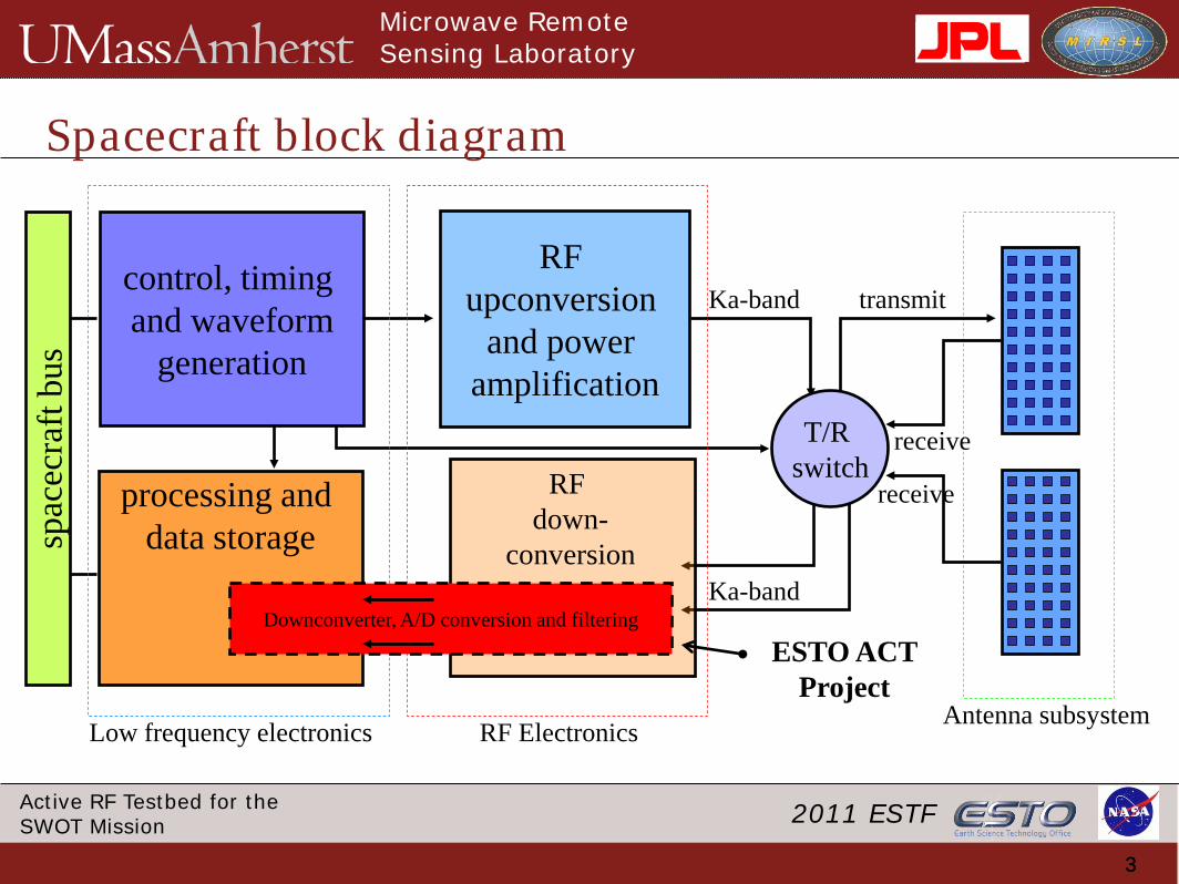
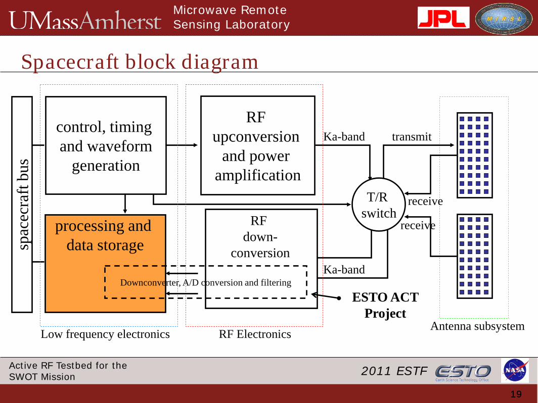
Spacecraft block diagram
33
control, timing and waveform
generation
RF upconversion
and power amplification
processing and data storage
Antenna subsystem
transmit
receive
receiveT/R switch
RF Electronics
spac
ecra
ft bu
s
Low frequency electronics
Downconverter, A/D conversion and filtering
RF down-
conversion
ESTO ACT Project
Ka-band
Ka-band
Microwave Remote Sensing Laboratory
2011 ESTFActive RF Testbed for the SWOT Mission
Block Diagram of RF Testbed
4
1.25 GHz ARB
HVPS
EIK
L-ba
nd L
O
Ka-
band
LO
Load
40 dB coupler
Load
40 dB coupler
Ka-band LO
2 x 3 GSamp/sec A/D & FPGA
Mass Data storage
Roc
ket I
/O o
r PC
I bus
Low data rate telemetry
telemetry sensors
upconverterdownconverter
* Shaded regions indicate ESTO funded development components
Microwave Remote Sensing Laboratory
2011 ESTFActive RF Testbed for the SWOT Mission
Spacecraft block diagram
55
control, timing and waveform
generation
RF upconversion
and power amplification
processing and data storage
Antenna subsystem
transmit
receive
receiveT/R switch
RF Electronics
spac
ecra
ft bu
s
Low frequency electronics
Downconverter, A/D conversion and filtering
RF down-
conversion
ESTO ACT Project
Ka-band
Ka-band
Microwave Remote Sensing Laboratory
2011 ESTFActive RF Testbed for the SWOT Mission
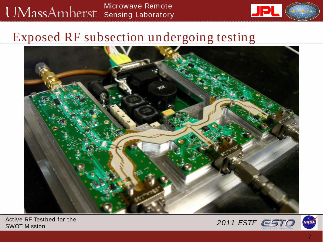
Ka-band downconverter development
6
•To improve isolation and thermal management, DC electronics were moved into a secondary cavity• drop-down walls isolate filter cavities• between-board connections made with Tusonix through-connectors. • L-band signal amplified to be directly sampled by A/D converter
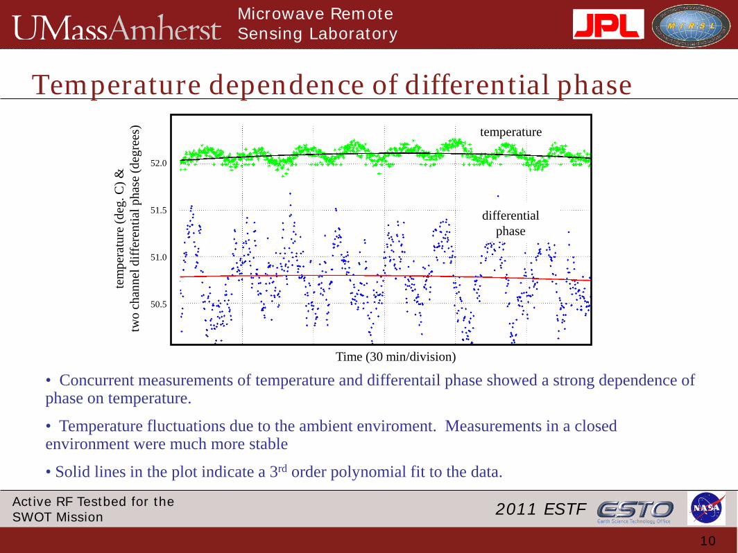
• Concurrent measurements of temperature and differentail phase showed a strong dependence of phase on temperature.
• Temperature fluctuations due to the ambient enviroment. Measurements in a closed environment were much more stable
• Solid lines in the plot indicate a 3rd order polynomial fit to the data.
Microwave Remote Sensing Laboratory
2011 ESTFActive RF Testbed for the SWOT Mission
Thermal Analysis
11
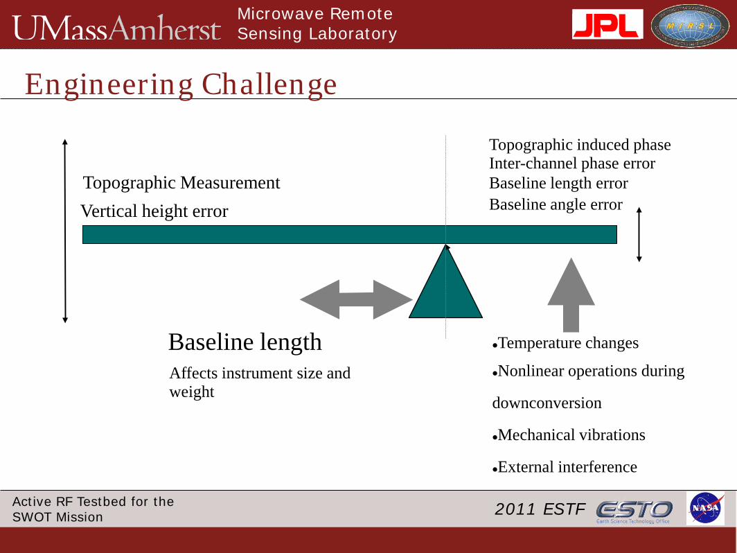
• 35 GHz signals have a wavelength of 8.4 mm.
• Changes in the physical path length due to thermal expansion/contraction, will cause changes in the signal phase as will temperature imbalances in active components
• A one degree phase change is equivalent to 23 µm of electrical path length change. Integrated over 5 cm of total path length, this is equivalent to a 0.05% expansion coefficient, or 5 parts in 10,000.
• Thermal imbalances between the two interferometric paths will thus induce a temperature dependent phase error.
• We are measuring temperature “on-board” so that this phase error may be monitored and corrected in the digital stage.
• Point measures of temperature are unlikely to be sufficient to characterize the phase error, as they do not take into account temperature distributions or the thermal inertia of the chassis
• Thermal modeling will help understand the source of thermal imbalance as it is distributed troughout the system
Microwave Remote Sensing Laboratory
2011 ESTFActive RF Testbed for the SWOT Mission
Measurements of Differential Phase
12
Low Frequency Electronics
Low Frequency Electronics
Two-Channel DownconverterSiO2 Cables
(5 inches)
Power splitter
Signal source
Diff
eren
tial P
hase
Mea
sure
men
t
3.5
cm
Microwave Remote Sensing Laboratory
2011 ESTFActive RF Testbed for the SWOT Mission
13
Thermal Testing and Characterization is a tricky affair
0.25oC/second, 15oC/min; -100oC to 300oC temperature range
Remote operation via serial port or IEEE-488 bus
downconverter
Microwave Remote Sensing Laboratory
2011 ESTFActive RF Testbed for the SWOT Mission
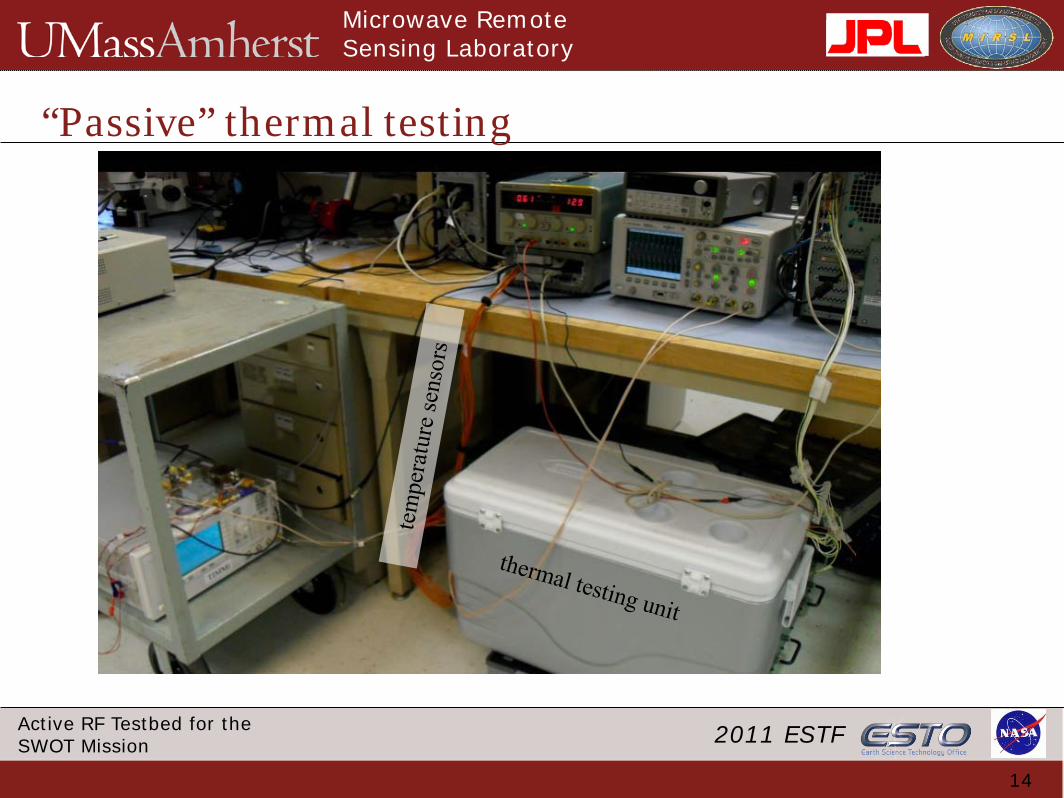
“Passive” thermal testing
14
Microwave Remote Sensing Laboratory
2011 ESTFActive RF Testbed for the SWOT Mission
A 3D-relief of previous Ka-band board
15
34.55 GHz LO in
Telemetry and regulated power
on-board temperature sensors
Used for COMSOL FEM modeling
Microwave Remote Sensing Laboratory
2011 ESTFActive RF Testbed for the SWOT Mission
2 55
-2 25
0 40
45
50
30
35
Temperature imbalance (oC) Temperature (oC)
1
-1
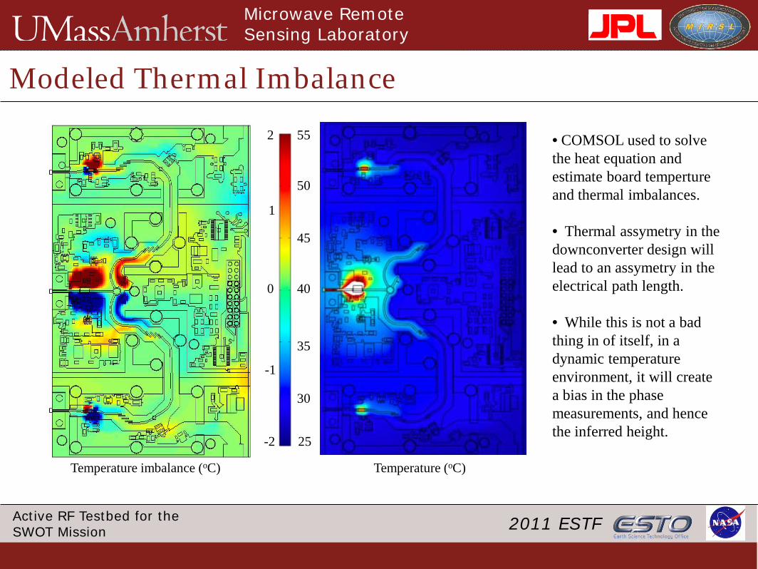
Modeled Thermal Imbalance
• COMSOL used to solve the heat equation and estimate board temperture and thermal imbalances.
• Thermal assymetry in the downconverter design will lead to an assymetry in the electrical path length.
• While this is not a bad thing in of itself, in a dynamic temperature environment, it will create a bias in the phase measurements, and hence the inferred height.
Microwave Remote Sensing Laboratory
2011 ESTFActive RF Testbed for the SWOT Mission
Dynamic Modeling of Temperature
17
T(t) = TSS − TSS − T0( )e−αtModel (emperical)
observed
• Dynamic modeling of temperature is challenging because of the complexity of the subject matter
• Absolute accuracy is less important than the ability to capture the low order derivatives
• As modeling improves, we will incorporate the results into the observed phase behavior between the two channels
• Similar model results have been obtained using COMSOL. An emperical model is used currently for tuning the COMSOL model.
• Results will be used to better inform the microwave engineering
Microwave Remote Sensing Laboratory
2011 ESTFActive RF Testbed for the SWOT Mission
Thermal Telemetry combined with Science Data
18
FPGAfiltering andtemperature
compensation
A/DChan 1 demux
A/DChan 2 demux
Thermal telemetry
two channelsof digital
output
Microwave Remote Sensing Laboratory
2011 ESTFActive RF Testbed for the SWOT Mission
Spacecraft block diagram
1919
control, timing and waveform
generation
RF upconversion
and power amplification
processing and data storage
Antenna subsystem
transmit
receive
receiveT/R switch
RF Electronics
spac
ecra
ft bu
s
Low frequency electronics
Downconverter, A/D conversion and filtering
RF down-
conversion
ESTO ACT Project
Ka-band
Ka-band
Microwave Remote Sensing Laboratory
2011 ESTFActive RF Testbed for the SWOT Mission
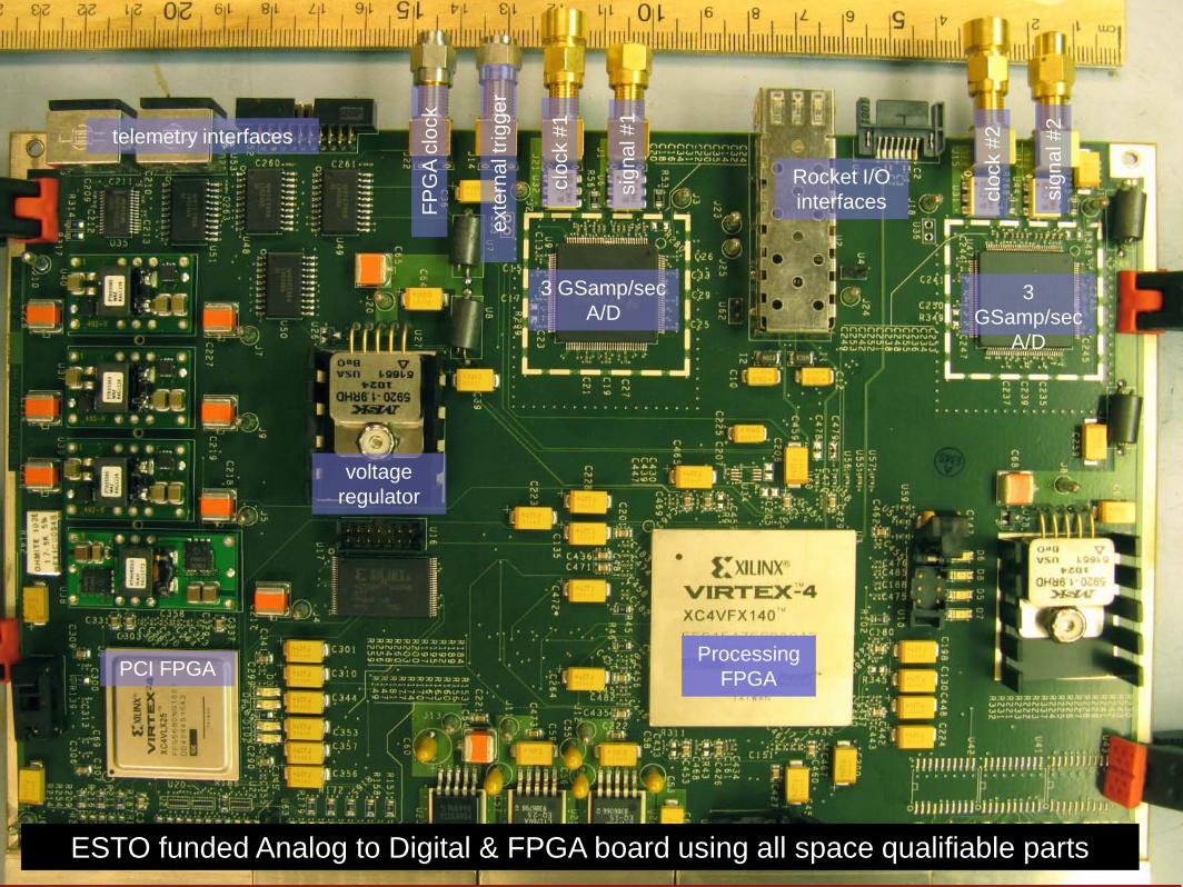
ESTO funded Analog to Digital & FPGA board using all space qualifiable parts
3 GSamp/sec A/D
3 GSamp/sec
A/D
Processing FPGAPCI FPGA
Rocket I/Ointerfaces
telemetry interfaces
cloc
k #1
cloc
k #2
sign
al #
1
sign
al #
2
FPG
A cl
ock
exte
rnal
trig
ger
voltage regulator
Microwave Remote Sensing Laboratory
2011 ESTFActive RF Testbed for the SWOT Mission
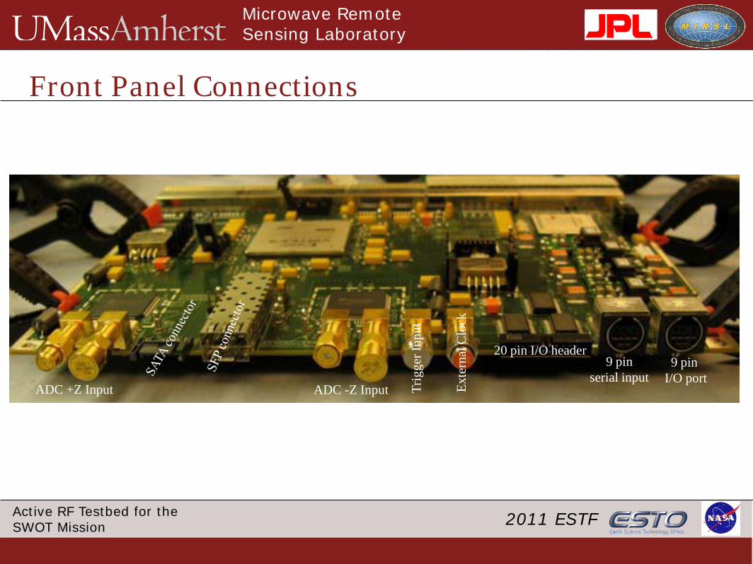
Front Panel Connections
ADC +Z Input ADC -Z Input Trig
ger I
nput
Exte
rnal
Clo
ck
20 pin I/O header9 pin
serial input9 pin
I/O port
Microwave Remote Sensing Laboratory
2011 ESTFActive RF Testbed for the SWOT Mission
A/D performance validation
22
• Residual errors are less than 1/100th of the input voltage (~40 dB in power)
• Dominated by quantization errors (7 bits ~ 44 dB QSNR)
• ENOB estimated to be 7 bits, close to the published ENOB of 7.2 bits
Microwave Remote Sensing Laboratory
2011 ESTFActive RF Testbed for the SWOT Mission
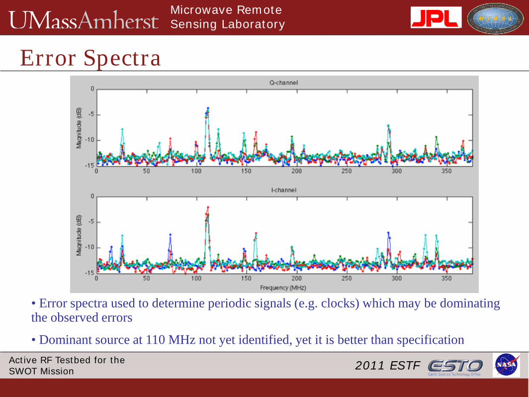
Error Spectra
• Error spectra used to determine periodic signals (e.g. clocks) which may be dominating the observed errors
• Dominant source at 110 MHz not yet identified, yet it is better than specification
• EIK Demand for large current from the HVPS at the PRF (4 kHz) causes an oscillation in the system phase performance
Microwave Remote Sensing Laboratory
2011 ESTFActive RF Testbed for the SWOT Mission
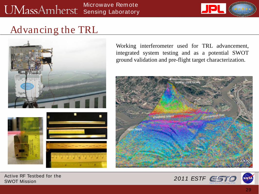
Advancing the TRL
29
Working interferometer used for TRL advancement,integrated system testing and as a potential SWOTground validation and pre-flight target characterization.
Microwave Remote Sensing Laboratory
2011 ESTFActive RF Testbed for the SWOT Mission
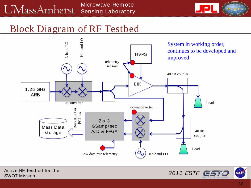
Block Diagram of RF Testbed
30
1.25 GHz ARB
HVPS
EIK
L-ba
nd L
O
Ka-
band
LO
Load
40 dB coupler
Load
40 dB coupler
Ka-band LO
2 x 3 GSamp/sec A/D & FPGA
Mass Data storage
Roc
ket I
/O o
r PC
I bus
Low data rate telemetry
telemetry sensors
upconverterdownconverter
System in working order, continues to be developed and improved
Questions?31
• We are continuing our expertise in Ka-band microwave technology development• Integration of RF hardware with digital subystems allows detailed analysis of error in components and across the system• Measurement accuity sufficient for measuring milligree variations in the propagation path• Hardware components are valid across a variety of NASA mission types (e.g. GRACE II, SWOT)