A Language-Based Approach to Run-Time Assurance for Autonomous Systems Sumukh Shivakumar Electrical Engineering and Computer Sciences University of California at Berkeley Technical Report No. UCB/EECS-2020-99 http://www2.eecs.berkeley.edu/Pubs/TechRpts/2020/EECS-2020-99.html May 29, 2020
Transcript
A Language-Based Approach to Run-Time Assurance forAutonomous Systems
Sumukh Shivakumar
Electrical Engineering and Computer SciencesUniversity of California at Berkeley
Permission to make digital or hard copies of all or part of this work forpersonal or classroom use is granted without fee provided that copies arenot made or distributed for profit or commercial advantage and that copiesbear this notice and the full citation on the first page. To copy otherwise, torepublish, to post on servers or to redistribute to lists, requires prior specificpermission.
Acknowledgement
I would like to deeply thank my advisor Sanjit A. Seshia, and my mentorsAnkush Desai and Hazem Torfah for their immeasurable guidance, support,and patience throughout my research journey. I would also like thank myfamily for their continuous, unconditional support and encouragement.
A Language-Based Approach to Run-Time Assurance for Autonomous Systems
by
Sumukh Shivakumar
A thesis submitted in partial satisfaction of the
requirements for the degree of
Master of Science
in
Electrical Engineering and Computer Sciences
in the
Graduate Division
of the
University of California, Berkeley
Spring 2020
A Language-Based Approach to Run-Time Assurance for Autonomous Systems
Sumukh Shivakumar
Research Project
Submitted to the Department of Electrical Engineering and Computer Sciences, University of California at Berkeley, in partial satisfaction of the requirements for the degree of Master of Science, Plan II. Approval for the Report and Comprehensive Examination:
Committee:
Sanjit A. Seshia Research Advisor
(Date)
* * * * * * *
Joseph E. Gonzalez Second Reader
(Date)
May 27, 2020
5/26/2020
1
Abstract
A Language-Based Approach to Run-Time Assurance for Autonomous Systems
by
Sumukh Shivakumar
Master of Science in Electrical Engineering and Computer Sciences
University of California, Berkeley
Distributed Mobile Robotics (DMR) systems are increasingly present in complex autonomousmissions, which creates excitement around autonomous robots, but raises questions of safety.Safety of these DMR systems cannot always be guaranteed at design time. To address this, weprovide a language-based approach for run-time assurance for robotic systems based on theRobot Operating System (ROS). We present SOTER, an updated run-time assurance (RTA)framework for building safe, distributed robotic systems on ROS. The SOTER frameworkspecifically contains a programming language for implementing reactive robotic software andan integrated run-time assurance system that allows programmers to use uncertified com-ponents, but still provide safety guarantees. We demonstrate the efficacy of SOTER usinga multi-robot surveillance case study, with multiple run-time assurance modules. Throughrigorous simulation, we show that SOTER enabled systems ensure safety, even when usingthird-party components.
I would like to deeply thank my advisor Sanjit A. Seshia, and my mentors Ankush Desaiand Hazem Torfah for their immeasurable guidance, support, and patience throughout myresearch journey. I would also like thank my family for their continuous, unconditionalsupport and encouragement.
1
Chapter 1
Introduction
There has been an increase in autonomous robots collaborating to perform complex missionsin recent times, which has created excitement around the future opportunities offered by dis-tributed mobile robotic (DMR) systems. These robotic systems are commonly involved indiverse and safety critical roles [7], but pose a particularly challenging problem with regardsto safety. When designing these DMR systems, safety often cannot be guaranteed uncondi-tionally at design time. These DMR systems also often contain 3rd party components, suchas machine learning based components, which are hard to verify for safety. One solution isto use formal verification and systematic testing techniques; however, these techniques areoften computationally expensive and have not yet caught up with this increased complexity[21]. There is hence a need to somehow monitor these DMR systems, in order to ensure thatthey are safe. In particular, there is a need for a systematic way to define monitors for DMRsystems so that can be directly integrated with common robot SDKs that are used to buildthese systems.
These DMR systems have found themselves in numerous use cases, such as packagedelivery systems, personal transportation, and surveillance. One approach to certifyingthese systems for safety is to use run-time assurance. This is where the programmer builds asystem at design time that has the ability to monitor itself and the surrounding environmentat run-time. This system also has the ability to switch to a formally verified safe mode ofoperation when necessary, even if this means degraded performance.
A popular run-time assurance framework is the Simplex architecture [22]. In the contextof robotic systems, this architecture is composed of three main components: (1) the advancedcontroller (AC) which controls the robot under normal operating conditions, (2) the safecontroller (SC) which has been previously certified to keep the robot within a safe regionof operation, often at degraded performance, and (3) the decision module (DM) which hasalso been previously certified to periodically monitor the robot’s state and its environmentto decide whether to switch from the advanced controller to the safe controller so that itremains with a safe region of operation.
Simplex-based Run-Time Assurance (RTA) frameworks operate with the advanced con-troller driving the system, paired with the decision module that monitors the overall system
CHAPTER 1. INTRODUCTION 2
every ∆ time to analyze whether the robot is in a state where its safety specification canbe violated within ∆ time. If it decides that the robot is in imminent danger, it switchescontrol from the advanced controller to the safe controller. These framework are useful, buthave limitations in their existing implementations. Many existing techniques [15] [1] [19]apply this framework to just a single component in the entire system, or wrap the entiresystem using a single Simplex module, making the design of the components of this moduleoften extremely difficult and complicated. Many prior applications also lack programminglanguage support for constructing these RTA systems in a module manner, optimizing onlyfor communication and timing of the system. Some approaches only focus on monitoringcapabilities [9] and do not provide a systematic method of switching from the safe controllerback to the advanced controller to minimize the overall performance hit. Most importantly,no prior work provides a comprehensive framework with language support for monitor gen-eration and Simplex-based run-time assurance on top of the Robot Operating System. Inorder to solve these issues, there is a need for a programming framework for building theseprovably safe robotic systems with run-time assurance that considers all facets of the softwarestack.
In this work, we build upon SOTER [4], a programming framework used to build saferobotic systems using run-time assurance. The goal of our work is to provide formal monitor-ing support and run-time assurance for general robot SDK’s by extending the SOTER systemto become much more modular in supporting a variety of robotics platforms. Specifically,we focus on refactoring the SOTER toolkit to support the Robot Operating System (ROS),which is a common robotics platform. The motivation largely stems from the DARPAAssured Autonomy project to ensure autonomous systems behave correctly as autonomyevolves with machine learning. This effort is in conjunction with Boeing, who have test bedsto vet these assured autonomy techniques. These test beds are largely built on top of theROS platform and so it is clear that having a version of this SOTER run-time assurancesoftware framework on top of the ROS platform would substantially aid in the use of run-time assurance on their automated taxiing project and help advance one avenue of assuredautonomy.
In SOTER, a program is built as a collection of nodes, which are periodic processes, thatcommunicate with other nodes in a publish-subscribe mode of communication. An RTAmodule written in the SOTER language, as in traditional RTA modules, is composed of anadvanced controller, a safe controller, and a safety specification which the decision moduleuses to switch between controllers. The programmer can construct these RTA modulesand specify timing behavior for the decision module so the pre-certified safe controller hasthe ability to switch back to the advanced controller to maximize overall performance of thesystem. SOTER importantly supports compositional construction of an overall RTA system.In other words, the SOTER contains constructs used to built RTA modules for individualcomponents of the system, and with many such RTA modules, the programmer is able toprovide security guarantees for the overall composite system. The SOTER toolkit itselfalso includes a compiler that generates C code that can be executed on top of the Mavlinksoftware platform.
CHAPTER 1. INTRODUCTION 3
In this work, we refactor the SOTER framework to support modular components thathelp port the system on to ROS. Through this process, we make a number of systems contri-butions in order to allow the SOTER integration on generic SDK’s just as ROS. This includesthe ability to compile SOTER programs directly as ROS nodes, having P programming lan-guage support in ROS’s native catkin workspace, and dynamically creating ROS nodes fromthe SOTER language, directly from application level code in the SOTER program.
In all, we provide a clear software stack for distributed mobile robotics as well as a pro-gramming framework for monitoring, which supports a Simplex-based run-time assurancesystem. This new implementation leverages the original SOTER compiler and generates ex-ecutable C code that can be directly ported on to robots in addition to simulation platformssuch as Gazebo [13] and Open AI gym [12]. We demonstrate the efficacy of this refactoredversion of the SOTER framework by building a multi-robot surveillance case study. Ourresults show that this SOTER framework can ensure the safety of multiple robots simulta-neously even in the presence of unsafe third-party components and controllers.
In summary, we make the following novel contributions:
1. A refactored programming framework for Simplex-based run-time assurance on top ofthe ROS platform.
2. SOTER/P language support for native ROS development.
3. A modular robotics software stack to build distributed mobile robotic systems.
4. A sample case study for multi-robot surveillance with multiple RTA modules on differ-ent components of the software stack that compose together meeting the overall safetyspecification of the system.
5. Experimental results in simulation on the ROS platform proving how SOTER can beused for guaranteeing correctness of a system in the presence of third-party unverifiedcomponents. Videos of our simulations can be found on https://drona-org.github.io/Drona/and implementation of our framework can be found at https://github.com/Drona-Org/Drona.
4
Chapter 2
Background
2.1 The P Language
The SOTER framework relies on being an asynchronous event-driven language. SOTERis largely built on top of the P language, which is a domain specific language meant towrite asynchronous event driven code easily [3]. It is designed to implement protocols thatdictate the interaction between concurrently executing components, which is essential forsafe execution of such programs. P also provides the tools in order to be able to createformally safe programs, which are verified through systematic testing. This naturally makesit a good fit for the SOTER language.
A P program is represented as a group of interacting state machines, and each of whichcommunicate asynchronously with events. Events themselves are queued onto a machine’sbuffer, a first-in-first-out queue, and machines are responsible for handling each of theseevents in a responsive manner. These events are commonly queued by other machines, butcan also be raised from the same machine as well. If a machine does not handle any one ofthe events that could be potentially enqueued, a failure is thrown during compilation, whichis detected during automatic verification.
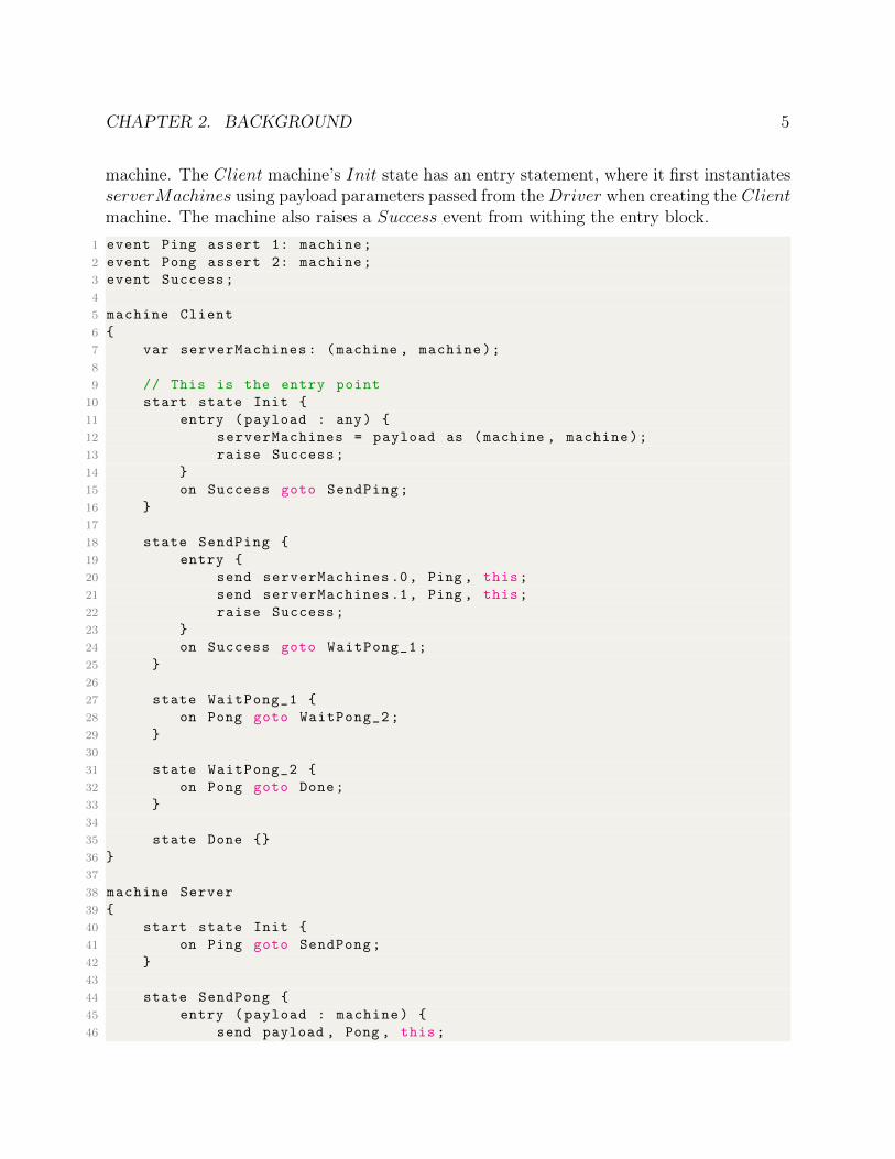
The PingPong P program shown below illustrates the features and semantics of the Planguage. This program contains 3 machines: Client, Server, and Driver. The goal ofthis P program is to create a Client machine that communicates with two Server machines.At a high level, the Client machine sends a Ping event to both of the Server machinessequentially and expects a reply from each one.
An event can be raised by a machine or can be sent from one machine to another. Inour PingPong example, the Server machine raises the Success event, which is queued ontoits own FIFO buffer from the SendPong state. Formally, each state description consistsof 4 elements: a state name, a set of events (called the deferred set), a set of event actionpairs (called action handlers), and a statement (called the entry statement), which getsexecuted when a state is entered. A machine contains control states, transitions, actions, andvariables. Events cause machines to transition into other states found within the same state
CHAPTER 2. BACKGROUND 5
machine. The Client machine’s Init state has an entry statement, where it first instantiatesserverMachines using payload parameters passed from the Driver when creating the Clientmachine. The machine also raises a Success event from withing the entry block.
1 event Ping assert 1: machine;
2 event Pong assert 2: machine;
3 event Success;
4
5 machine Client
6 {
7 var serverMachines: (machine , machine);
8
9 // This is the entry point
10 start state Init {
11 entry (payload : any) {
12 serverMachines = payload as (machine , machine);
13 raise Success;
14 }
15 on Success goto SendPing;
16 }
17
18 state SendPing {
19 entry {
20 send serverMachines .0, Ping , this;
21 send serverMachines .1, Ping , this;
22 raise Success;
23 }
24 on Success goto WaitPong_1;
25 }
26
27 state WaitPong_1 {
28 on Pong goto WaitPong_2;
29 }
30
31 state WaitPong_2 {
32 on Pong goto Done;
33 }
34
35 state Done {}
36 }
37
38 machine Server
39 {
40 start state Init {
41 on Ping goto SendPong;
42 }
43
44 state SendPong {
45 entry (payload : machine) {
46 send payload , Pong , this;
CHAPTER 2. BACKGROUND 6
47 raise Success;
48 }
49 on Success goto End;
50 }
51
52 state End {
53 entry {
54 raise(halt);
55 }
56 }
57 }
58
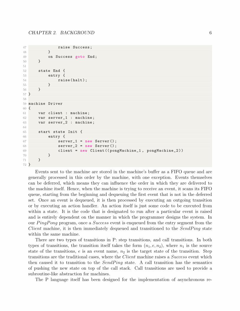
59 machine Driver
60 {
61 var client : machine;
62 var server_1 : machine;
63 var server_2 : machine;
64
65 start state Init {
66 entry {
67 server_1 = new Server ();
68 server_2 = new Server ();
69 client = new Client (( pongMachine_1 , pongMachine_2))
70 }
71 }
72 }
Events sent to the machine are stored in the machine’s buffer as a FIFO queue and aregenerally processed in this order by the machine, with one exception. Events themselvescan be deferred, which means they can influence the order in which they are delivered tothe machine itself. Hence, when the machine is trying to receive an event, it scans its FIFOqueue, starting from the beginning and dequeuing the first event that is not in the deferredset. Once an event is dequeued, it is then processed by executing an outgoing transitionor by executing an action handler. An action itself is just some code to be executed fromwithin a state. It is the code that is designated to run after a particular event is raisedand is entirely dependent on the manner in which the programmer designs the system. Inour PingPong program, once a Success event is enqueued from the entry segment from theClient machine, it is then immediately dequeued and transitioned to the SendPing statewithin the same machine.
There are two types of transitions in P: step transitions, and call transitions. In bothtypes of transitions, the transition itself takes the form (n1, e, n2), where n1 is the sourcestate of the transitions, e is an event name, n2 is the target state of the transition. Steptransitions are the traditional cases, where the Client machine raises a Success event whichthen caused it to transition to the SendPing state. A call transition has the semanticsof pushing the new state on top of the call stack. Call transitions are used to provide asubroutine-like abstraction for machines.
The P language itself has been designed for the implementation of asynchronous re-
CHAPTER 2. BACKGROUND 7
sponsive systems, and so it has many built in tools that help the programmer with thisimplementation. One of the biggest support tools P provides within the compiler itself ischecking for unhandled events with automatic verification. If an event arrives in a state andthere is no transition defined for this event, then the verifier throws an unhandled eventviolation. Of course there are certain situations in which the designer of the system wouldwant to delay handling of such events or dropping/ignoring the events all together. In thesesituations, P allows for these events to be members of the deferred set, and in this case theverifier at compilation time will not flag the events as unhandled. The verifier however alsohas a built-in liveness check that disallows deferring events indefinitely long. This ensuresthat the verifier is not simply silenced because every event is in the deferred set.
Under the hood, a P program itself is compiled down from these high level semantics intoa “core language” where state descriptions are tuples in the form (n, d, s1, s2), where n is astate name, d is a set of deferred events, s1 is an entry statement, and s2 is an exit statement.A P program reduced to its core language consists of event declarations, a nonempty list ofmachines, and one machine creation statement. Each event declaration also contains a listof types which are sent with an event as payload. Machine declarations now in this corelanguage consist of (1) a machine name, (2) a list of events, (3) a list of variables, (4) alist of actions, (5) a list of states, (6) a list of transitions, and (7) a list of action bindings.Each variable event in the high level P semantics, as seen in the PingPong program, has adeclared type, and currently P supports int, byte, bool, event, and machine identifier types.
The P compiler takes these P programs and compiles them down to executable C code.The C code is automatically generated with statically allocated data structures, as defined inthe P compiler, and these data structures are examined by the P run-time when it executesthe operational semantics of the program. The P run-time contains all of the functionalityfor executing operational P semantics, such as creating machines and enqueueing events onto specific machines. Most of this functionality is kept private to the run-time; however,when integrating another driver framework with the P compiler, often times the run-timeneeds modifications and foreign functions need to be implemented.
A critical feature of the core language and semantics of the P language is that it allowsfor the use of foreign functions. This feature is very important in the context of writingreal world asynchronous code. To support 3rd party codebases and external code, P allowsthe programmer to call functions written in the C programming language directly from Pprograms. These functions are called from within specific P machines and therefore needto be introduced to the machine’s scope with a declaration that gives the function’s nameand type signature. The run-time semantics of the foreign functional is nearly identical toa standard C method call. Chapter 3 shows how one must rely on this functionality of P inorder to be able to interface with the Robot Operating System’s (ROS) C++ API for theSOTER implementation and experiments.
In all, the goal of the P programming language is to allow the programmer to unifymodeling and programming into one activity. Not only can a P program be compiled intoexecutable C code, but it can also be verified using model checking techniques. With itsemphasis on asynchronous event-driven programming, P makes a natural choice to use for
CHAPTER 2. BACKGROUND 8
SOTER, which relies on many underlying features of P. Our SOTER implementation canbe built as an extension to the existing P language, making the necessary changes to theexisting P compiler in order to support the run-time assurance language primitives.
2.2 Drona Framework
In order to build this run-time assurance framework for robotic systems, we must also havea reliable framework in which to build and coordinate distributed mobile robotic systems.One of the key components/dependencies to making our SOTER implementation viableon ROS based systems is Drona [2]. Drona is a software framework for building reliabledistributed mobile robotics applications. It enables the programmer to program an ensembleof robots with formal guarantees and high assurance of correct operation. Distributed mobilerobotics (DMR) systems are those which involve teams of networked robots navigating aphysical space to coordinate and accomplish specific tasks. In general distributed mobilerobotics systems are becoming increasingly prevalent in complex safety-critical applications[2]. Drona aims to bridge the gap between such systems and providing high assurance andprovable guarantees on such systems to enable large scale adaptation. Drona considers theclass of DMR systems where the robots are in a known workspace with static obstacles andthe tasks to be performed by the robots are generated dynamically. A task represents movinga single robot to a specified goal location.
One of the fundamental problems when working with a team of mobile robotics that sharethe same workspace is that the programmer must design the system to prevent collisions andstill compute optimal motion plans for the individual robots. Additionally, it is difficult toprogram autonomous reactive robots to properly handle dynamically generated events.
Drona makes the process of building these systems easier by integrating the P languageinto the Drona tool-chain. As mentioned in section 2.1, P aids the programmer in imple-menting and specifying asynchronous and event-driven programs. In this case, the Dronasoftware stack can be represented as a series of interacting state machines that communicatewith a series of asynchronous events. The P programs are then compiled into C code whichcan be deployed on a number of robotic systems with the proper interfaces, such as Mavlink[11].
A DMR system implemented using Drona software stack consists of both event-drivenasynchronous processes and periodic processes. Hence, Drona has been termed to be amixed-synchronous system. DMR systems written in Drona can be formally verified usingP’s built model checking system, Zing. The model checking approach is based on the notionof approximate synchrony where the clocks of each of the robots are not necessarily syncedbut bounded within a given limit.
The Drona software stack can be divided into 3 main components: the task planner, thesoftware stack, and the robot SDK as displayed in Figure 2.1.
The task planner is where the programmer implements application specific protocolsto guarantee that the system satisfies the application specific goals. In the example for a
CHAPTER 2. BACKGROUND 9
Figure 2.1: DMR Software Stack from [2]
priority mail drone delivery system, the task planner is responsible for ensuring that themail requests are handled responsively by individual drones and are always delivered inpriority order. In an effort to achieve this goal and have a particular drone visit a specificlocation in the workspace, the task planner sends a request to the motion planner, a separatecomponent inside the DMR software stack. The motion planner is responsible for computinga trajectory to the goal location. The multi-robot motion planner module is responsible forcomputing safe and collision-free trajectories for each of the robots by coordinating with allother robots within the system. Once the trajectory is computed, the motion planner thensends this trajectory to the plan executor module. It is important to note that the motionplanner is a modular component that allows the programmer to swap the multi-robot motionplanner with other third-party motion planners, such as the Open Motion Planning Library(OMPL) motion planner [23]. Once the motion planner has computed a path for the robot,it then sends this path back to the Task Planner which forwards it to the Plan Executormodule. The Plan Executor module is responsible for interacting with the robot SDK tophysically execute the robots’ paths in accordance to their designated trajectories. The PlanExecutor module ensures that the robot properly follows and executes the path provided bythe Motion Planner module.
The Sense and Infer module within the software stack implements monitors that contin-uously look at a variety of sensor streams from their respective robot and informs the TaskPlanner if there is something awry and needs immediate attention. The monitors themselvesare also represented as state-machines, following P language semantics with asynchronous,event-driven flow of communication between the other Drona stack components. In the ex-
CHAPTER 2. BACKGROUND 10
ample of a battery monitor, the P state machine would view inputs streams from the robot’sbattery sensor and inform the task-planner when the battery level of the robot is below acertain threshold.
The final component of the overall DMR stack is the Robot SDK. Often times, robotmanufacturing companies provide a software development kit that provides robot primitivesand functions that allow the programmer to controller robot operations. This SDK alsosamples the state of the robots and often enables inter-robot communication as well. Froma formal verification perspective, the DMR software stack is verified under the assumptionthat the robot SDK is correct.
Currently, the robot SDK that the Drona software stack support is the Micro Air Ve-hicle Link (MAVLink) protocol [11]. It is a protocol meant for communicating with smallunmanned vehicles. MAVLink is a very lightweight messaging protocol for communicatingwith drones specifically. It follows a modern publish-subscribe communication model andthe point-to-point design pattern. The MAVLink toolchain uses XML message definitionsto generate MAVLink libraries. MAVLink, in addition to providing communication betweenthe drones, enables communications between the drone and a ground control station.
The Drona software framework contains four main components: an event-driven pro-gramming language for implementing and specifying a DMR application, a reliable DMRsoftware stack, a model checking backend for efficiently verifying the DMR system, and arun-time library for executing the generated C code on a designated robot SDK [2]. Thesoftware framework is an extension to the state-machine based programming language P, sothat generated C code from the P compiler can be executed on top of the MAVLink protocol.The language is also extended with primitives for specifying workspace configuration. Belowis a diagram showing the Drona tool chain.
Figure 2.2: Drona Software Framework from [2]
The Drona application, which the programmer implements using the aforementioned ex-tension to the P language, also consists of four subcomponents. The four subcomponentsinclude a workspace configuration XML file, and implementation block, a specification block,
CHAPTER 2. BACKGROUND 11
and the test-driver/environment block. The workspace config XML file provides the detailsregarding workspace information. This information includes the number of robots present inthe static workspace, the robot starting positions, locations of all static obstacles, the loca-tions of charging stations for each robot, and any other static workspace related information.Many of the configuration details of the workspace is Task Planner specific, so dependingon the application goals, the programmer can add additional relevant information. In thispriority mail delivery experiment, designated battery charging stations were added for eachof the robots. The specification block is where application specific correctness propertiesare defined. The specifications themselves are implemented as monitors, or spec monitormachines in the P language. The implementation block is the main collection of P state-machines where the Task Planner is implemented. This is where the programmer designsand develops the Task Planner component from the DMR stack based on application specificgoals. Lastly, the test-driver block implements the finite environment state machines thatclose the DMR system for verification.
The Drona compiler, which is an extension of the P compiler, generates a translationof the application into the Zing modeling language. Zing, in this implementation, has beenextended to support mixed-synchronous abstraction to automatically check if the programsatisfies the desired properties expressed in the specification block. The compiler also turnsthe DMR application into C code that is compiled by a standard C compiler and linkedagainst the Drona/P run-time and MAVLink to generate the executable code that can bedeployed on to the robot or the simulator.
One of the biggest drawbacks of the vanilla Drona implementation is that it does notnatively support robotics systems based on the Robot Operating System (ROS). As describedin Chapter 3, one of the main contributions of this research effort has been in migrating Dronato become much more flexible in supporting a variety of other robot SDKs, namely ROS.
2.3 SOTER Framework
Framework Overview
This implementation of SOTER that supports the Robot Operating System, heavily relieson the previous work that comes from the original SOTER paper [4], which provides thetheoretical basis for a lot of the work that will be described later. Before that, it is importantto understand the theoretical underpinnings that make the design of such a language possible.As previously mentioned, there has been a recent movements towards achieving greaterdegrees of autonomy and intelligence in robotic systems that also strongly correlates with thecomplexity of these systems. Especially with the recent drive towards including third-partymachine learning components, it is extremely challenging to provide design-time certification,and formal safety guarantees.
One way to minimize the divide between increasingly complex robotic systems and thesafety guarantees that can provided is to incorporate techniques of run-time assurance. This
CHAPTER 2. BACKGROUND 12
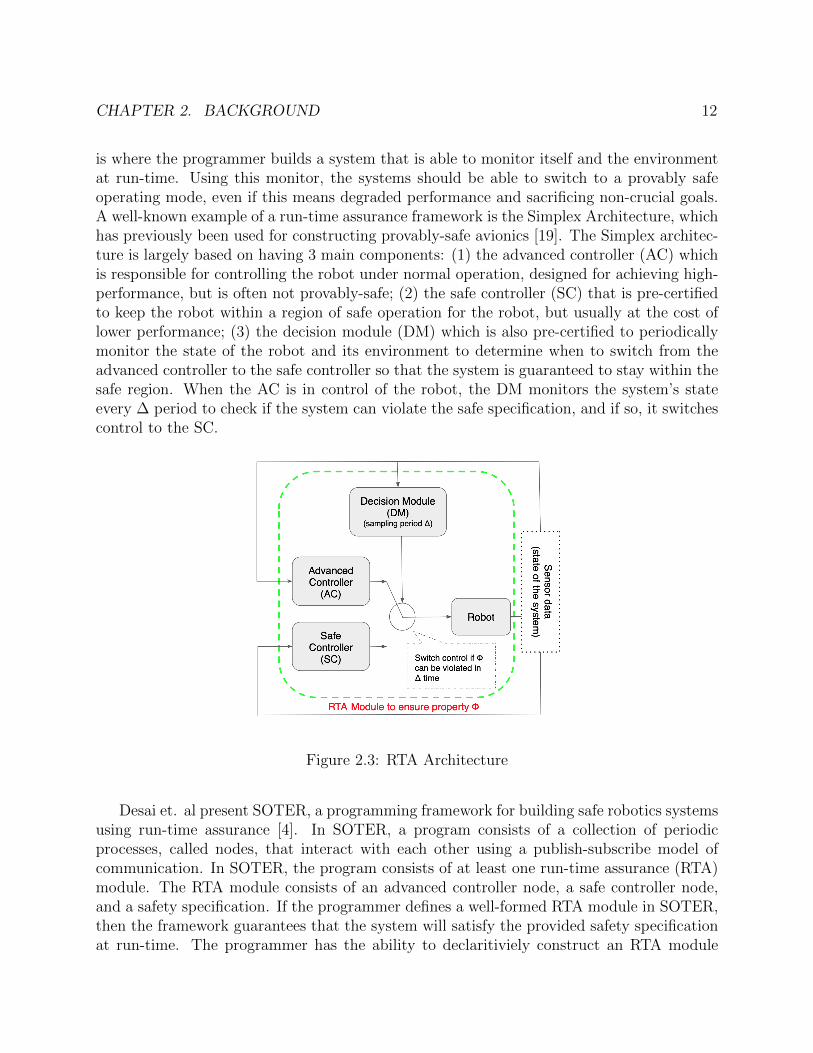
is where the programmer builds a system that is able to monitor itself and the environmentat run-time. Using this monitor, the systems should be able to switch to a provably safeoperating mode, even if this means degraded performance and sacrificing non-crucial goals.A well-known example of a run-time assurance framework is the Simplex Architecture, whichhas previously been used for constructing provably-safe avionics [19]. The Simplex architec-ture is largely based on having 3 main components: (1) the advanced controller (AC) whichis responsible for controlling the robot under normal operation, designed for achieving high-performance, but is often not provably-safe; (2) the safe controller (SC) that is pre-certifiedto keep the robot within a region of safe operation for the robot, but usually at the cost oflower performance; (3) the decision module (DM) which is also pre-certified to periodicallymonitor the state of the robot and its environment to determine when to switch from theadvanced controller to the safe controller so that the system is guaranteed to stay within thesafe region. When the AC is in control of the robot, the DM monitors the system’s stateevery ∆ period to check if the system can violate the safe specification, and if so, it switchescontrol to the SC.
Figure 2.3: RTA Architecture
Desai et. al present SOTER, a programming framework for building safe robotics systemsusing run-time assurance [4]. In SOTER, a program consists of a collection of periodicprocesses, called nodes, that interact with each other using a publish-subscribe model ofcommunication. In SOTER, the program consists of at least one run-time assurance (RTA)module. The RTA module consists of an advanced controller node, a safe controller node,and a safety specification. If the programmer defines a well-formed RTA module in SOTER,then the framework guarantees that the system will satisfy the provided safety specificationat run-time. The programmer has the ability to declaritiviely construct an RTA module
CHAPTER 2. BACKGROUND 13
with specified timing behavior, combining provably-safe operation with the feature of usingthe advanced controller whenever safe to achieve good performance. SOTER provides aproper way for the decision module to switch back from the safe controller to the advancedcontroller, which extends the traditional RTA framework and providing higher performance,since it is in the system’s best interest to maximize AC utilization whenever safe to do so.
As mentioned before, SOTER provides a high-level domain specific language. Addition-ally, it supports compositional construction of RTA systems. The SOTER language includesconstructs that decompose the overall RTA systems into individual RTA modules that areindividually monitored and composed in order to provide overall security guarantees for theentire system. SOTER also includes a compiler that generates the decision module nodethat implements the switching logic. It also generates C code to be directly executed usingrobot SDKs, such as MAVLink.
When using the SOTER framework, the programmer first needs an application layer tospecify objectives for the robotic system. For the purpose of this overview, we can use a robotsurveillance system as our application. At the top of the SOTER stack, is the applicationlayer where the programmer specifies system goals, in this case ensures that all surveillancepoints are visited indefinitely. The application creates target locations for a specific robot.The application layer then communicates with the motion planner to compute a series ofway points for the robot to visit that target point. This motion planner communicatesthese way points sequentially to a motion primitives library, which takes each way point andgenerates a low level control for the robot to follow the trajectory computed. It is importantto note that the underlying dynamics of these controllers, which have usually not been pre-certified for safety, causes deviations from the true reference path. When implementingthis application protocol, the programmer often uses many such uncertified components.Examples include third party solvers or libraries like the Open Motion Planning Library[23] to compute way points for the robot. Likewise, motion primitives are themselves oftenlearned using Reinforcement Learning [10], or provided by third-parties without consideringsafety [8]. In the presence of such uncertified components, it is difficult to provide formalguarantees of safety at design time, especially when the components themselves are hard toverify.
As mentioned, SOTER is a high-level domain specific language based on publish-subscribemodel of communication. A SOTER program is a collection of periodic processes that publishand subscribe on a variety of topics, or communication channels. Fig. 2.3 is an exampleof the SOTER semantics for node creation as well as how nodes publish and subscribe tospecific topics.
In the example provided in Figure 2.4, a topic titled targetWaypoint is created which is acommunication channel that supports messages of type coord, which was previously declaredas a tuple of floats. This is followed by a node declaration with title MotionPrimitive thatsubscribes to topics localPosition and targetWaypoint. For the purposes of this example,the localPostition topic creation has been omitted. The MotionPrimitive node also publishesonto the controlAction topic as well. The node runs periodically every 10ms, reads messagesfrom the subscribed topics, performs local computations, and then publishes that control
CHAPTER 2. BACKGROUND 14
Figure 2.4: SOTER Semantics
action on the controlAction topic.In the real world, the motion primitives, represented by the motion primitive node,
generate control actions to go from the current position to the target position using a thirdparty controller provided by the robot manufacturer. This controller can be consideredour advanced, unverified controller in the context of the Simplex architecture mentionedbefore. These low level controllers often use approximations when modeling the dynamicsof the robot, making the simulation performance optimal, not safety optimal. As mentionedalready, this is the very same motivation to have a run-time assurance module in the SOTERframework.
Figure 2.5: RTA-Protected Motion Primitive from [4]
CHAPTER 2. BACKGROUND 15
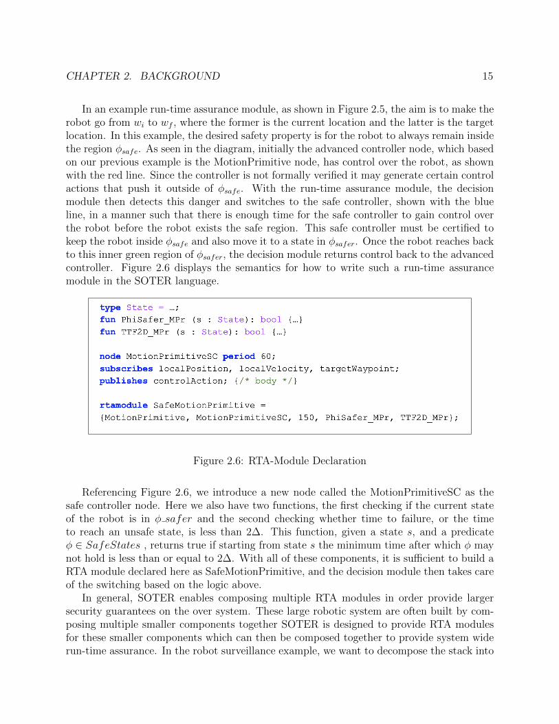
In an example run-time assurance module, as shown in Figure 2.5, the aim is to make therobot go from wi to wf , where the former is the current location and the latter is the targetlocation. In this example, the desired safety property is for the robot to always remain insidethe region φsafe. As seen in the diagram, initially the advanced controller node, which basedon our previous example is the MotionPrimitive node, has control over the robot, as shownwith the red line. Since the controller is not formally verified it may generate certain controlactions that push it outside of φsafe. With the run-time assurance module, the decisionmodule then detects this danger and switches to the safe controller, shown with the blueline, in a manner such that there is enough time for the safe controller to gain control overthe robot before the robot exists the safe region. This safe controller must be certified tokeep the robot inside φsafe and also move it to a state in φsafer. Once the robot reaches backto this inner green region of φsafer, the decision module returns control back to the advancedcontroller. Figure 2.6 displays the semantics for how to write such a run-time assurancemodule in the SOTER language.
Figure 2.6: RTA-Module Declaration
Referencing Figure 2.6, we introduce a new node called the MotionPrimitiveSC as thesafe controller node. Here we also have two functions, the first checking if the current stateof the robot is in φ safer and the second checking whether time to failure, or the timeto reach an unsafe state, is less than 2∆. This function, given a state s, and a predicateφ ∈ SafeStates , returns true if starting from state s the minimum time after which φ maynot hold is less than or equal to 2∆. With all of these components, it is sufficient to build aRTA module declared here as SafeMotionPrimitive, and the decision module then takes careof the switching based on the logic above.
In general, SOTER enables composing multiple RTA modules in order provide largersecurity guarantees on the over system. These large robotic system are often built by com-posing multiple smaller components together SOTER is designed to provide RTA modulesfor these smaller components which can then be composed together to provide system widerun-time assurance. In the robot surveillance example, we want to decompose the stack into
CHAPTER 2. BACKGROUND 16
3 components: (1) an RTA-protected motion planner, (2) a battery safety RTA module, and(3) an RTA-protected motion primitive module.
Run-Time Assurance Module
Here, we will formalize the different components of the RTA module.A topic is formally defined a tuple (e, v), where e ∈ E represents the unique name of the
topic and E is the universe of all topic names. v ∈ V is the value that is posted on this topicfrom V , the universe of of all possible values that can be communicated using topic e.
A node in SOTER can be described as a period input-output state-transition: at everytime instant, the node reads the values on its input topics, updates its own state, andpublishes values on its output topics. Formally, a node is a tuple (N,I,O,T,C) where (1) N∈ N is the unique name for the node from the set of all nodes, (2) I ⊂ E is the set of alltopics this node is subscribed to, (3) O ⊆ E is set of all topics which this node publishesto, (4) T ⊆ L × (I → V ) × L × (O → V ) is the transition relation of the node (the nodelistens to I, transitions its local state and publishes to O), (5) C = {(N, t0), (N, t1), ...} isthe time-table representing the times t0, t1, ... at which the node N takes a step.
Moving to the run-time assurance module, let S represent the state space of the system,i.e. the set of all possible configurations of the system. The desired safety property isrepresented as φsafe ⊆ S, meaning the goal is to maintain the robot inside the φsafe set.
The RTA module can be formally represented as a tuple (Nac, Nsc, Ndm,∆, φsafe, φsafer).
1. Nac ∈ N is the AC node
2. Nsc ∈ N is the SC node
3. Ndm ∈ N is the decision module (DM) node
4. ∆ ∈ R+ represents the period of DM
5. φsafe ⊆ S is desired safety property
6. φsafer ⊆ S is stronger safety property
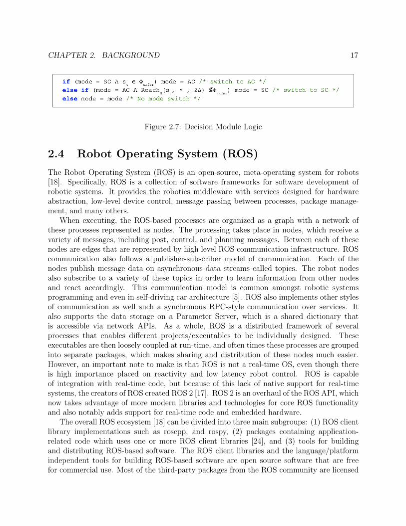
Figure 2.7 below, displays the switching logic that sets which controller is in charge of theRTA module given the current state of the system. The DM node evaluates this switchinglogic once every ∆ time units. We can see that if the robot state is in φsafer, then it switchesfrom Nsc to Nac. The ReachM(s, *, t) ⊆ S represents the set of all states reachable in time[0,t] from the current state, using any controller and so the DM checks if the system willremain inside φsafe in the next 2∆ time. If not, then Nsc must take control until broughtback to φsafer.
CHAPTER 2. BACKGROUND 17
Figure 2.7: Decision Module Logic
2.4 Robot Operating System (ROS)
The Robot Operating System (ROS) is an open-source, meta-operating system for robots[18]. Specifically, ROS is a collection of software frameworks for software development ofrobotic systems. It provides the robotics middleware with services designed for hardwareabstraction, low-level device control, message passing between processes, package manage-ment, and many others.
When executing, the ROS-based processes are organized as a graph with a network ofthese processes represented as nodes. The processing takes place in nodes, which receive avariety of messages, including post, control, and planning messages. Between each of thesenodes are edges that are represented by high level ROS communication infrastructure. ROScommunication also follows a publisher-subscriber model of communication. Each of thenodes publish message data on asynchronous data streams called topics. The robot nodesalso subscribe to a variety of these topics in order to learn information from other nodesand react accordingly. This communication model is common amongst robotic systemsprogramming and even in self-driving car architecture [5]. ROS also implements other stylesof communication as well such a synchronous RPC-style communication over services. Italso supports the data storage on a Parameter Server, which is a shared dictionary thatis accessible via network APIs. As a whole, ROS is a distributed framework of severalprocesses that enables different projects/executables to be individually designed. Theseexecutables are then loosely coupled at run-time, and often times these processes are groupedinto separate packages, which makes sharing and distribution of these nodes much easier.However, an important note to make is that ROS is not a real-time OS, even though thereis high importance placed on reactivity and low latency robot control. ROS is capableof integration with real-time code, but because of this lack of native support for real-timesystems, the creators of ROS created ROS 2 [17]. ROS 2 is an overhaul of the ROS API, whichnow takes advantage of more modern libraries and technologies for core ROS functionalityand also notably adds support for real-time code and embedded hardware.
The overall ROS ecosystem [18] can be divided into three main subgroups: (1) ROS clientlibrary implementations such as roscpp, and rospy, (2) packages containing application-related code which uses one or more ROS client libraries [24], and (3) tools for buildingand distributing ROS-based software. The ROS client libraries and the language/platformindependent tools for building ROS-based software are open source software that are freefor commercial use. Most of the third-party packages from the ROS community are licensed
CHAPTER 2. BACKGROUND 18
under many open source licenses as well. These packages are often used for common roboticsystem functionalities such as robot models, perception, planning, simulation tools, hardwaredrivers, mapping, and many other algorithms.
ROS client libraries are primarily built for Unix systems and officially supports theUbuntu Linux operating system, because of the open source software dependencies of thelibraries themselves. Other operating systems are “supported” by the community, but arelargely under experimental development.
The overall goal of the Robot Operating System is to facilitate code reuse in roboticsdevelopment, and in support of this goal there are a number of features that ROS possessesthat make it a very appealing choice for robotics research. Such features include, easytesting with ROS’s builtin unit testing framework, language independence with ROS alreadyhaving a C++ and Python API, ROS’s thinness making it easy to port and integrate withother frameworks, ROS-agnostic libraries, and scalability, making it appropriate for largedevelopment processes. All of these features make ROS such a widely used framework forrobotics research as a whole, warranting the shift to ROS for both the Drona and SOTERimplementation.
19
Chapter 3
Run-Time Assurance with SOTER onROS
This chapter outlines the main contributions of this work, namely the new architecture ofthe SOTER framework, how it achieves assurance on robotic systems based on the RobotOperating System, and the multi-robot surveillance case study we use to evaluate the efficacyof the framework. The approach we took to designing this framework was to re-design eachcomponent and create a narrow interface of communication between each component andthe Robot SDK, though separate Cpp modules. Using this framework, the user simplyneeds to build their program using the SOTER language at the application level, usingthe components outlined below, and the SOTER framework will automatically create theexecutable Cpp code that interfaces with the ROS ecosystem. Because we specifically focuson the ROS, we make our framework flexible enough to where any ROS developer can createtheir ROS packages in their native catkin workspace, but now using SOTER code. Thisarchitecture makes it a very modular framework that fits perfectly into traditional roboticsdevelopment.
3.1 Architecture Overview
The design goal of this new SOTER architecture is to have clearly defined components thatabstract different levels of the generic robotics software stack. As mentioned, a huge concernfor programming and creating highly reactive robotic systems is to properly handle non-deterministically generated asynchronous events. Hence, we integrate the P state-machinebased programming language as the basis for this SOTER framework. Looking at Figure 3.1,the general idea of our architecture is to have the programmer simply implement applicationlogic at a high level using SOTER, and have the rest of our framework use these declarationsto generate the necessary components in order to accomplish those application goals. Thegoal is to have the programmer interact with high-level constructs and declaratively buildthese robotic systems with monitoring capabilities, and have the framework remove a lot of
CHAPTER 3. RUN-TIME ASSURANCE WITH SOTER ON ROS 20
the overhead that comes with building these systems traditionally. Hence, we organize thearchitecture as seen in Figure 3.1, with modular components that create many abstractionsbetween different levels of the framework.
Organizing the various components as P state machines helps simplify the process ofimplementing and specifying asynchronous event-driven programs. For this reason, the ar-chitecture of our refactored version of SOTER on the Robot Operating System borrows fromthe original Drona DMR stack with some notable differences. These differences include newmodules in the Software Stack and a completely different methodology for communicatingwith the Robot SDK. This new narrow interface of communication to the Robot SDK en-ables efficient communication, easily monitor-able components, and portability on to otherSDKs.
At a high level, looking at Figure 3.1, the programmer primarily interfaces with theTask Planner, where they implement application specific goals. The Task Planner will haveone or more robot machines, which are the actual robots used in the application. Eachof these robots maps to destinations using their own motion planner, and these plans areexecuted by the plan executor module. For monitoring, the programmer interfaces withthe Sense and Infer module, where they implement monitors that observe certain propertiesof the application. Lastly each of these components interface the Robot SDK through athin middleware termed Cpp Modules, which abstract away many of the underlying detailsneeded for ROS programming, and make them accessible in the SOTER language.
The new architecture has been designed such that migrating to new alternatives to ROSin the future incurs minimal overhead, and is flexible to support even ROS 2 [17], LCM[16], MAVLink [11], and ZeroMQ [26], just to name a few. We will outline the new SOTERarchitecture by first describing each of the components in the framework, as shown in Figure3.1.
Task Planner
For the purposes of illustrating the different features of the SOTER framework, we will beusing a robot surveillance sample case study. We use this case study for later evaluatingour framework as well. Starting with the top of the stack, we have the application, whichwe term the Task Planner. The Task Planner is where the programmer implements all ap-plication specific goals. In the context of the robot surveillance example, this applicationlayer implements the robot surveillance protocol that ensures the application specific prop-erty, which is to have multiple robots visit a series of different points indefinitely. This iswhere the programmer includes information on how to instantiate individual robots, whattopics/events they’re are subscribed to, and which points individual robots must visit. Theprogrammer encodes all of this information using the P language. The Task Planner alsois in charge of setting up the Robot SDK interface, in this case the ROS interface. Wewill discuss this more later when discussing the middleware necessary to integrate P intoa ROS-based workflow. It is also important to note that the Task Planner is often imple-mented as a multi-threaded P state machine, so this much of the communication happens
CHAPTER 3. RUN-TIME ASSURANCE WITH SOTER ON ROS 21
asynchronously, especially in the multi-robot case. In the surveillance protocol, the singleinstance of the Task Planner is often communicating to two separate robots concurrently inorder to have both robots visit locations simultaneously, covering more workspace area inless time for our specific application.
Figure 3.1: SOTER Framework Architecture
Robot State Machine
As shown in Figure 3.1, the next components in the SOTER architecture are the Robotmachines. Each of these P based state machines are instantiated from the Task Plannerdirectly and each one represent a different robot as part of the application. Hence, therecan be multiple instantiations of the generic robot state machine. The robot machine isresponsible for subscribing and listening to events published by the Task Planner for eachindividual robot, and to act accordingly. In the robot surveillance example, there are twoinstances of the Robot machine and each robot is responsible for listening to locations sentby the Task Planner. The robot machines also have to initialize themselves with the RobotSDKs, in this case ROS, as soon as they are instantiated by the Task Planner. This is partof the middleware necessary to integrate P into the ROS SDK. The robot machines also needto know the presence of other robots in their workspace, and so the task planner provides
CHAPTER 3. RUN-TIME ASSURANCE WITH SOTER ON ROS 22
each robot with the information required to learn the positions and communicate with all ofthe other robots in the application.
Motion Planner
Each Robot state machine creates a designated motion planner state machine. The goalof the motion planner machine is create a path with a series of way points to reach aparticular destination in the workspace. With an instantiation for each robot state machine,the motion planner accordingly only computes paths for a specific robot. Hence, when a robotstate machine receives a specific destination points from the Task Planner, this informationthen gets transmitted to the the respective motion planner to compute the correspondingpath. The reason for this separation and multiple instances of the motion planner in thestack is again to fulfill the original goal of having the multiple robots survey the workspaceconcurrently. With this architecture, each robot can compute its own specific paths for itsown destinations. The separation of the motion planner from the robot itself allows for amore modular design. This is helpful especially since there are many options for third-partymotion planners; this design allows a programmer to swap motion planners easily withouthaving to re-architect their full robotics stack. In the robot surveillance case study, we usethe Open Motion Planning Library (OMPL) motion planner [23] in order to compute paths.In our case, we use the OMPL library out of the box, which also relies on a custom workspaceparser library to take into account the initial locations of the robots, static obstacles, andother key features of the workspace. This workspace parser reads an XML file to read inthis information. This is also particularly important when using multiple motion plannersconcurrently, which is often the case in the Simplex architecture for run-time assurance.The original SOTER paper has an example with a performant AC motion planner next toa verifiable, safe motion planner, where control is swapped based of the decision module[4]. One thing to note about this motion planner design is that it takes advantage of theP language’s ability to be able to call external function written in the C language, throughforeign functions as described in Chapter 2. These motion planner machines are hence ableto make third party C function calls easily from directly inside the P program, which makesit even easier to integrate third-party motion planners who have C/Cpp APIs. These foreignC functions live in a separate C module that can then be compiled with the P program andexecuted together. This is the implementation we use in the robot surveillance case study.We will further discuss the compilation process when describing ROS integration with theP language.
Plan Executor
Each of the motion planner machines for their respective robots, creates an instance of a PlanExecutor state machine. The Plan Executor machine’s goal is to be able to physically executea path, which is defined by a series of way points in order to reach a destination point, on aspecific robot. Hence, each Plan Executor is also uniquely mapped to a specific robot in the
CHAPTER 3. RUN-TIME ASSURANCE WITH SOTER ON ROS 23
workspace. The Plan Executor listens for paths from its corresponding motion planner, andthen interfaces with ROS through foreign functions in order to physically execute the pathon to their respective robot. In this case, because ROS only has a Cpp API, we call a Cppforeign function that gets masked as a C function later down the line with the compiler. Moreon this interface will be discussed later. Now looking at Figure 3.1, we see a clear, ordered,logical chain of P state machines from the Task Planner, to the Robot State Machines, totheir respective Motion Planners, to their respective Plan Executors. These machines areintentionally constructed for events to not only be sent down stream, but also upstream. Asmentioned, the overall framework is a multi-threaded application where many aspects of theprogram will run asynchronously. However, this flow of sending and executing one locationat a time to the Robot machine needs to be happen sequentially. Hence, we use threadblocking in P semantics (using the send/receive blocks) to stop further execution of thesemachines until notified otherwise. More concretely, once the Motion Planner computes itspath for a specific target destination, the Motion Planner sends this path to its Plan Executorand then halts all further execution until the Plan Executor finally finishes executing theROS goToDestination function, which only terminates when the robot has finally reachedthat destination point. The Plan Executor then sends an event to the Motion Plannernotifying its completion, and then the Motion Planner also sends this completion messagefurther upstream to the Robot machine to signal it to send the next point that as beenqueued from the Task Planner. This clearly separated design for the Software Stack enablesthis bidirectional communication which is essential, and otherwise difficult to implement inrobotic systems.
ROS Integration
In order to understand the ROS integration into our P based DMR software stack, we mustfirst overview the traditional ROS development flow using its official build system, catkin[25]. Catkin is a collection of CMake macros and associated code used to build softwarepackages, in this case ROS based packages. To build any ROS-based project, you mustfirst create this project from within a catkin workspace. The catkin workspace is dividedinto 3 categories: (1) Source Space, (2) Build Space, and (3) Development Space. Thesource space is where all source code of the catkin package resides. The build space is whereCMake is called to build the catkin packages that are found in the source space. CMake isa cross-platform open source tool to manage the build-process of software using a compiler-independent method [14]. It can traditionally be used to build C/Cpp based projects, whichis appropriate for ROS Cpp projects. The development space, also termed the devel space, iswhere the built targets are placed prior to being installed. There is also an inexplicit installspace, which does not reside in the workspace. This is where targets are installed, once theyare built. Certain packages contain specific nodes, which reside in the source space. Thesenodes are specific executable programs within the package. Once these packages are builtand installed, specific nodes can be run using the rosrun package_name node_name command.
CHAPTER 3. RUN-TIME ASSURANCE WITH SOTER ON ROS 24
Now before proceeding, we must first overview how traditional P programs are compiledand executed. This will help motivate the integration process with ROS and the catkinworkspace. Traditionally, P programs are constructed in either one or more .p files usingthe semantics described in Chapter 2. These P files are then compiled using the P compiler,which is a .NET Core application. This compiles all of the P programs automatically intoC code. In order to actually execute the P program, there needs to be a driver C programwith a traditional main method that calls the PrtMkMachine(...) function from the P run-timedirectly on the driving P machine found in the P program. This is to tell the executable whichP state machine to start execution from. With this Main.c file along with the newly compiledC files as a result of calling the P compiler on the relevant P files, we now have at least 2 Cfiles that need to be built and executed. In P, this done using CMake, so the programmeris responsible for creating a CMakeLists.txt file with the relevant files and libraries, whichincludes all of the P run-time. After running cmake, this generates a traditional executableof the P program which can then be run from the command line.
Now having described how both ROS and P operate as standalone systems, we can nowdescribe how to integrate both. We will describe this process in the context of our robotsurveillance case study to concretize the steps taken. To start, we have left the ROS buildsystem exactly the same with the traditional catkin flow. The only change in the ROSflow is in the source space for our specific package. We start by creating a stand alonecatkin package for our project, which we call Drona. This Drona package found in the catkinsource space then contains separate nodes for different tasks/applications. Within this Drona
package is where we stray from the traditional ROS development flow. Here we populateour software stack with a series of P files, one for each of the components of the SOTERrobotics stack. These P state machines have various responsibilities, some of which are verydependent on the ROS SDK. In these cases, we use foreign function calls from directly in P.These foreign functions live in separate Cpp modules that directly interact with ROS usingthe roscpp API. It is important to note that traditionally P programs only support C foreignfunctions, so we need to use the extern "C" declaration for each of our foreign functions. Thismakes the function-name in Cpp have C linkage so that the client C code, which will be theP to C compiled programs, can link to these functions using a compatible C header file thatcontains the declarations of these functions. This is enough to be able to call these Cppfunctions from with the P program. Now with the properly formatted foreign functions, theP program is ready to be compiled to C using the traditional dotnet compiler. We also needto make a change to the way we create the driver C program that runs the full P program.Now because the P programs rely on ROS functionality, there is some setup that is requiredeven before calling PrtMkMachine, on the first driving P machine. Since again this ROS setupis only possible using the roscpp API, this driver program also now needs to be a cpp filewith all ROS initialization and then the call to PrtMkMachine to initialize the first P machinewhich in our case is the TaskPlanner machine. We now have all Cpp files containing foreignfunctions, the compiled C files from our P programs, and the driver Cpp program to initializethe TaskPlanner. We now create the necessary CMake files and incorporate all of these files inaddition to any external dependencies. In our drone surveillance example, we also needed to
CHAPTER 3. RUN-TIME ASSURANCE WITH SOTER ON ROS 25
include the P run-time, the OMPL motion planner, and the external workspace parser whichis used by the OMPL motion planner. The combination of multiple CMake files help declarethe executable P program has a ROS executable inside of our Drona catkin package. Thishelps then interface with these executable P programs as any traditional ROS executableand so we can use the rosrun command as before. Even in the traditional ROS developmentflow, the programmer often has multiple nodes and packages running simultaneously, witheach package tasked with a specific application. In our case study, we have the Drona packageas the executable robot software and we have a separate multi_robot package that launches agazebo simulation of the actual robots used to run our robot surveillance application. Thissimulation catkin package is the physical workspace to run experiments, and therefore has tohave the same features as found in the xml workspace file used as part of our OMPL motionplanner.
Overall with this kind of decoupled architecture between the software stack and theRobot SDK, out SOTER implementation of a generic DMR software stack is now muchmore modular, making ports to other Robot SDKs far simpler. Through the use of foreignfunctions and CMake, we can easily include any generic 3rd party SDK with a C/Cpp APIeasily.
Sense & Infer Module / Run-Time Assurance
Transitioning into run-time assurance for our SOTER implementation, the final componentof our DMR software stack as shown in Figure 3.1 is the Sense and Infer module. TheSense and Infer module is where the programmer is able to include monitors that use avariety of sensors from the robot and observe different properties of the system. Monitorsare also responsible for providing run-time assurance based on their observations. Hence,the monitors also implement the decision module logic where they are able to switch controlfrom the advanced controller to the safe controller based on the state of the system. Theconstruction of the monitors themselves is largely dependent on the RTA module and desiredsafety specification of the application. In general the monitors also interface with manyproperties of the robot or simulation itself which is all available through the ROS SDK, andhence the Sense and Infer module as a whole also has a dependence on ROS. Like with thepreviously described components, the Sense and Infer module is entirely implemented as aseries of P state machines and because of the ROS dependencies, they again use the Cppforeign functions from directly within the monitors with a setup similar to that which wasdescribed in the ROS Integration.
To aid in our discussion of what goes into the construction of these P based monitors, wewill now draw upon the specific run-time assurance modules used in our robot surveillancecase study. The first monitor we construct is a Battery monitor that observes batterypercentage of the robot. The desired safety property we want for our software stack isto provide battery safety, that prioritizes safely bringing the robot to the charging stationwhen the battery charge falls below a threshold level. Hence, there needs to be a Batterymonitor for each of our robots. The monitor itself first gets initialized by the corresponding
CHAPTER 3. RUN-TIME ASSURANCE WITH SOTER ON ROS 26
Robot state machine with the necessary information to observe the corresponding robot.The battery machines each make foreign Cpp function calls that retrieve the current batterypercentage of the robot. We consider the robot to be in a safer state if its battery percentageis above 85%. We design our decision logic, the ttf2∆ function, based on the maximumamount battery discharge that could happen in 2∆ time and the maximum charge requiredto bring the robot to its corresponding charging station. We will go into the specifics of theconstruction of this RTA in the evaluation section, but given the construction of this functionwe repeatedly call this function in a loop every ∆ time and if the monitor senses that thebattery percentage will fall below 85%, then the monitor calls a very specially constructedCpp foreign function SwitchACToSC(...) which switches control from the advanced controller,which receives the current motion plan from the Motion Planner machine and forwards itto the Plan Executor machine, to the safe controller, which is a certified planner that safelybrings the robot from its current position to the charging station. Once the robot hassafely recharged at the charging station, the decision logic will sense that there is no longerimminent danger and call another foreign function SwitchSCToAC to return control back to theadvanced controller from the safe controller.
The next P based monitor we use in our robot surveillance case study is a location basedmonitor in order to geofence our grid-like workspace. In this experiment, our robots travelto a variety of points in a 5 x 5 grid. However, we consider the robot to be in the saferstate when in the inner 4 x 4 grid, and safe if in the difference in the outer border, outsideof the 4 x 4, but still within the 5 x 5. If the robot is outside of the 5 x 5, then it is inan unsafe state. Hence, in order provide such safety guarantees, we construct a P monitorthat exclusively monitors the location of the robot. It is important to note that just likein the battery monitor case, we have a separate monitor for each of the robots, geofencingeach independently. The monitor itself follows a similar construction to the battery example,since it also behaves as the decision module. This location based monitor gets instantiatedfrom each of the respective Robot state machines. The monitor then repeatedly makes aforeign cpp function call MonitorLocation(...) to observe the robot location. Our ∆ for thisRTA module is 0.5 seconds and we design our design logic using this value in addition tothe current position and the velocities of the robots in order to decide whether the robotwill be in an unsafe state within 2∆. Using this check that happens every ∆ time, we againuse the same foreign function SwitchACToSC(...) to switch to the safe controller when dangeris imminent. In this case the Safe Contoller is a certified planner that safely brings therobot back towards the center of our workspace, moving away from the geo fenced barrier asquickly as possible. The monitor still observes the location of the robot and switches backto the advanced controller once back into a safer state using SwitchSCToAC(...).
The third P based monitor we use in our robot surveillance case study is again anotherlocation based monitor, but this time to prevent collisions between robots. In this case, wehave a separate location monitor that gets spawned, not at the robot level, but at the TaskPlanner level, where it monitors locations of all the robots simultaneously. In our robotsurveillance case study, we have two robots simultaneously navigating the workspace and sowe want to make sure that the robots’ paths never cross, causing a collision. In this case,
CHAPTER 3. RUN-TIME ASSURANCE WITH SOTER ON ROS 27
the robot is in a safer state if the robot is more than 0.5 units away from any other robot,and in a safe state if the robot is between 0.3 and 0.5 units away from another robot. If therobot is less than 0.3 units from another robot, then it is considered in an unsafe state. Thismonitor also acts as the decision module for each of the robots and periodically observes eachrobot using the MonitorLocation(...) foreign Cpp function every ∆ time, which is again 0.5seconds. The decision logic again uses the velocity of each robot in addition to each positionto determine if it’s in danger. If so, it calls the SwitchACToSC(...) to switch to the safecontroller which is a certified planner to move the robot back 0.5 units until out of collisionterritory. Once the robot is back into a safe state, the monitor calls SwitchSCToAC(...) toreturn control to the advanced controller, which is a node that receives the current motionplan from the planner to move towards to the original destination point and forwards it tothe Plan executor to execute it using the motion primitives provided by the ROS SDK.
P Interrupt Mechanism
In this architecture, the way the decision modules/monitors switch control from the ad-vanced controller to the safe controller is by interrupting the execution of the Plan Executormodule. At this stage, the Plan executor interfaces with the Cpp modules in order to prop-erly execute plans provided by the motion planner. Currently, the Sense and Infer module,which houses the monitors, is indirectly interrupting this flow of execution by switching con-trol at the Cpp module level. However, ideally we need a mechanism that interrupts theflow of execution at the P language level. The monitors implemented in the Sense and Infermodules need to directly interrupt the Plan Executor, rather than interrupting the functioncalls the Plan Executor makes from the Cpp modules to interface with ROS. This is so thatwe abstract away as much Cpp code as possible and stick to implementing all flows in thisframework using the SOTER language exclusively. Currently, the P language, which we usefor implementation, does not support any sort of interrupt mechanism, where event basedcommunication and action handlers can be halted in between. We leave this implementationof an interrupt mechanism in the P language as future work.
3.2 Language/Systems Contributions for SOTER
Integration on ROS
This section builds off the ROS Integration subsection, where we describe the key languageand systems contributions we make in order to support SOTER/P on top of the ROS plat-form specifically. This section intends to enumerate the specific contributions and capabilitiesthat are now possible with ROS development using the SOTER framework.
CHAPTER 3. RUN-TIME ASSURANCE WITH SOTER ON ROS 28
Compiling P Programs as ROS nodes
Using this refactored SOTER framework, developers can now execute programs in the Planguage as traditional ROS nodes. Programmers are able to create ROS packages just asbefore, but they can now include P code as part of those packages. Traditionally, ROSdevelopers have a source space where they include all of the application specific code for aspecific package. This space can now also include P files, which are then compiled downto executable Cpp ROS executables. These executables can be run just as before withthe command rosrun ros_package ros_executable, which can be called from the ROS catkinworkspace. Traditionally SOTER/P programs are compiled down to executable C code. Inthis work, we make modifications to the compilation process of these processes in order tosupport the traditional catkin compilation process of ROS. These P programs are compiledso that they can be executed natively by the ROS Master node.
Dynamic ROS node generation from the P language
Through this SOTER framework, we now have the ability to dynamically create ROS nodeswith their own publishers and ROS callbacks from Task Planner at the P language level. Us-ing this, you can create a Robot machine in P, and all the setup for its publisher, subscriber,and call back information will automatically be handled in the Cpp modules, abstractingaway overhead of traditional ROS programming. The publish and subscribe method ofcommunication is used to control the dynamics of the robot, but is something the SOTERdeveloper does not have to worry about as they are only concerned with moving the robotto a series of way points. The callback information is used to provide support for lots of themonitoring capabilities. Again, the P programmer does not need to concern themselves withthe details of how the monitor is capturing its information. Rather, they have the ability tosimply create monitors that interface with these callbacks. We store all of this P to ROSinformation in a series of maps, so that there is a one to one correspondence between the Pprogram and the ROS nodes.
As part of this dynamic node generation, we split ROS initialization and all the publish/-subscribe nodes. Traditionally ROS programs have to do some initialization of the masternode and all publishers/subscribers at the start of the main program that drives their en-tire ROS program. We now have many different components in our software stack that arewritten in P and P programs themselves have a driver C program that initializes the mainP machine. In this framework, we decoupled the ROS initialization process between thisdriver C program, which now had to be modified to a Cpp program, and moved all otherROS initialization into Cpp modules that are called dynamically as new components in Pare initialized.
CHAPTER 3. RUN-TIME ASSURANCE WITH SOTER ON ROS 29
Cpp Integration for P programs
Through this framework, we had to make some modifications to how P programs are compiledso that they can be connected to the ROS ecosystem. One of the main changes we neededto make was to integrate Cpp into P programs, instead of C, since ROS only supports a CppAPI. P programs traditionally are compiled into executable C code, but this is problematicwith the ROS Cpp API. This required some changes to the P compilation process, which isnow directly integrated with the ROS compilation process. We had to specifically modify thedriver C program for P to support Cpp, the functions associated with this driver program(mainly used for making the P program multi-threaded), and all the foreign functions toCpp, since many had ROS dependencies.
P Integration with third party simulators
Through this framework, in order to actually drive robots using the Robot Operating System,we needed the P code to interface with third party simulators. This is so that the changes inthe Task Planner at the SOTER/P level, directly resulted in modifications at the simulationlevel. Through this refactor, we were able to integrate executable P code with third partysimulators. In our case study, we were able to compile and run our P code on a third partygazebo simulator.
3.3 Evaluation
We empirically evaluate the SOTER framework by building an RTA protected robot surveil-lance software stack that satisfies the following safety invariant: φbattery ∧φgeofence∧φcollision.The goal of our evaluation is to show how this new SOTER framework can be used tobuild a safe software stack for a sample case study, where each component provides securityguarantees and satisfies its own safety specification. An important feature of this SOTERarchitecture is the ability switch from the advanced controller to the safe controller andback, in order to maximize performance. We also empirically evaluate our software stackusing rigorous simulation to show that the RTA-protected software stack ensures safety ofthe system even in the presence of third party components, where the system would haveotherwise failed.
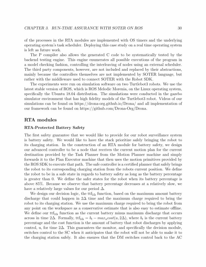
SOTER Framework / Experimental Setup
The SOTER framework itself is largely built on top of the state machine based programminglanguage, P. For this reason, it also has the ability to take advantage of many of the toolsbuilt into the P language. Specifically, it uses the compiler, the P run-time, and the backendsystematic testing engine. The compiler first checks that all components are properly formedand converts the syntax of the P language into executable C code. The P to C run-time thenexecutes this program by using the C representations of the nodes. The periodic behavior
CHAPTER 3. RUN-TIME ASSURANCE WITH SOTER ON ROS 30
of the processes in the RTA modules are implemented with OS timers and the underlyingoperating system’s task scheduler. Deploying this case study on a real time operating systemis left as future work.
The P compiler also allows the generated C code to be systematically tested by thebackend testing engine. This engine enumerates all possible executions of the program ina model checking fashion, controlling the interleaving of nodes using an external scheduler.The third party components, however, are not included and replaced by their abstractions,mainly because the controllers themselves are not implemented by SOTER language, butrather with the middleware used to connect SOTER with the Robot SDK.
The experiments were run on simulation software on two Turtlebot3 robots. We use thelatest stable version of ROS, which is ROS Melodic Morenia, on the Linux operating system,specifically the Ubuntu 18.04 distribution. The simulations were conducted in the gazebosimulator environment that has high fidelity models of the Turtlebot3 robot. Videos of oursimulations can be found on https://drona-org.github.io/Drona/ and all implementation ofour framework can be found on https://github.com/Drona-Org/Drona.
RTA modules
RTA-Protected Battery Safety
The first safety guarantee that we would like to provide for our robot surveillance systemis battery safety. We would like to have the stack prioritize safely bringing the robot toits charging station. In the construction of an RTA module for battery safety, we designour advanced controller to be a node that receives the current motion plan for the currentdestination provided by the Task Planner from the Motion Planner machine and simplyforwards it to the Plan Executor machine that then uses the motion primitives provided bythe ROS SDK to execute that path. The safe controller is a certified planner that safely bringsthe robot to its corresponding charging station from the robots current position. We definethe robot to be in a safe state in regards to battery safety as long as the battery percentageis greater than 0. We define the safer states for the robot when its battery percentage isabove 85%. Because we observe that battery percentage decreases at a relatively slow, wehave a relatively large values for our period ∆.
We design our decision logic, the ttf2∆ function, based on the maximum amount batterydischarge that could happen in 2∆ time and the maximum charge required to bring therobot to its charging station. We use the maximum charge required to bring the robot fromany point on the workspace as a conservative estimate that is also easy to estimate offline.We define our ttf2∆ function as the current battery minus maximum discharge that occursacross in time 2∆. Formally, ttf2∆ = bt −maxucost(u, 2∆), where bt is the current batterypercentage and the cost function is the amount of battery that robot discharges by applyingcontrol, u, for time 2∆. This guarantees the monitor, and specifically the decision module,switches control to the SC when it anticipates that the robot will not be able to make it tothe charging station safely. It also ensures that the DM switches control back to the AC
CHAPTER 3. RUN-TIME ASSURANCE WITH SOTER ON ROS 31
when the robot is sufficiently charged, which only happens once the robot has sufficientlyreached at least 85% charge. Figure 3.2 shows a snapshot from our simulation where robotsare approaching their respective charging stations, abandoning their original destinations,when battery is low and the monitor senses that the robots may not have enough charge toreach the destination and arrive at the charging station safely.
Figure 3.2: Battery Simulation
RTA for Geofencing
The second safety guarantee that we would like to provide for our robot surveillance systemis geofencing. We would like the software stack to prioritize safely bringing the robot backwithin the safe grounds of the workspace. In the construction of this RTA module forgeofencing, we design our advanced controller to be a node that receives the current motionplan for the current destination provided by the Task Planner from the motion plannermachine that uses the motion primitives provided by the ROS SDK to execute that path.The safe controller is a certified planner that safely brings the robot back towards the centerof the workspace, out of the less safe outer boundary of our 5 x 5 grid workspace. Wedesign the robot to be in a safe state as long as the robot has a longitude and latitudebetween 0 and 5, inclusively. Formally, 0 ≤ robotid,x ≤ 5 ∧ 0 ≤ robotid,y ≤ 5. We define
CHAPTER 3. RUN-TIME ASSURANCE WITH SOTER ON ROS 32
the safer states for the robot when its in the middle 4 x 4 subgrid within the workspace, or0.5 ≤ robotid,x ≤ 4.5 ∧ 0.5 ≤ robotid,y ≤ 4.5. Because location of the robot changes quiterapidly we have the smallest ∆ period possible of 0.5 seconds, since this is the minimumamount of time needed to refresh the ROS callback in order to read all robots’ positionsfrom the monitors.
Figure 3.3: Geo-Fence Simulation
We design our ttf2∆ function based on the maximum amount the robot can move in anydirection under any control in 2∆ time. We define our ttf2∆ as the current position of therobot and the maximum distance change in 2∆ time. This maximum distance is computedunder the hood as a function of ∆, as well as the x and y components of the velocity of therobot at time t. Because we have also capped the speeds of the robots themselves, we caneasily estimate worst case behavior as a conservative estimate which in turn guarantees thatthe decisions module switches control to the SC when the robot is in only the safe region,and headed outside of the 5 x 5. In this instant, the SC will gain control and bring the robotfrom its current position towards the center of the workspace until it reaches the the saferregion, in which the AC will gain control of the robot once again, as it attempts to visit thenext destination provided by the Task Planner. Figure 3.3 is a snapshot from our simulationand shows the robot moving back to safety and visually depicts the boundaries of what issafer, safe, and unsafe. The robot is attempting to go back to the gray safer zone, as it wasoriginally in the yellow safe zone, but on its way to visit a point in the red unsafe zone.
CHAPTER 3. RUN-TIME ASSURANCE WITH SOTER ON ROS 33
RTA for Collision Avoidance
The third safety guarantee that we would like to provide for our robot surveillance system iscollision avoidance. We would like the software stack to prioritize safely maneuvering out ofcrashes with other robots in the event where their motion plans cause their paths cross. In theconstruction of this RTA module for collision avoidance, we design our advanced controllerto be a node that receives the current motion plan for the current destination providedby the Task Planner from the Motion Planner machine that uses the motion primitivesprovided by the ROS SDK to execute that path. The safe controller is a certified plannerthat safely moves the robot back by 0.5 units radially from the to be collision point. Therobot is in a safe state if the robot is more than 0.3 units away from the other robot, ordist(robot1, robot2) ≥ 0.3. The robot is in a safer state if dist(robot1, robot2) ≥ 0.5. Becauselocation of the robot changes quite rapidly we have the smaller ∆ period of 0.5 seconds.
Figure 3.4: Collision Avoidance Simulation
We design our ttf2∆ function very similar to the geofence version of the ttf2∆ function.The function is based on the maximum amount the robot can move in any direction underany control in 2∆ time. We define our ttf2∆ as the current position of the robot and themaximum distance change in 2∆ time. This maximum distance is computed under the hoodas a function of ∆, as well as the x and y components of the velocity of the robot at timet. Because we have also capped the speeds of the robots themselves, we can easily estimate
CHAPTER 3. RUN-TIME ASSURANCE WITH SOTER ON ROS 34
worst case behavior as a conservative estimate which in turn guarantees that the decisionmodule switches control to the SC when the robot is in the safe (and not safer) region, andheaded to crash with the other robot. In this instant, the SC will gain control and bring therobot from its current position radially backwards from the collision point until it reachesthe the safer region and has one robot wait until the other robot completes its plan, in whichthe AC will gain control of the robot once again, as it attempts to visit the destination pointprovided by the Task Planner. Figure 3.4 is a snapshot from our simulation that showsrobots have successfully avoided colliding into one another, where both robots move radiallyout from their original collision point, and one waits as the other completes its plan andmoves on to its next destination.
Rigorous Simulation
Figure 3.5: Results of Rigorous Simulation
To show that the SOTER frameworks aids in building robust robotics systems with secu-rity guarantees, we conducted rigorous stress testing of the RTA-protected robot surveillancesoftware stack. We conducted software in the loop simulations, where the 2 autonomousrobots were tasked to visit randomly generated surveillance points in the Gazebo 5 x 5 Gridworkspace, while avoiding static obstacles. Totally, the robots drove for approximately 2hours of simulation, which was plenty given the relatively small size of our workspace therobots were exploring. We conducted this simulation 4 times and we found that on averagethere were 313 total disengagements, where the advanced controller switched over to thesafe controller to avoid a potential safety violation. The majority of these disengagementswere due to geo-fencing, where robots would try to explore outside of the boundaries of whatis considered safe, and we can attribute this relatively high number again to the relativelysmall size of the workspace. The recovery times of geo-fencing was relatively small, so it didnot hurt overall performance. With all three RTA modules in action, we found that that
CHAPTER 3. RUN-TIME ASSURANCE WITH SOTER ON ROS 35
several instances of returning control to the AC after recovering the system as well. Duringour rigorous simulation, the AC nodes were in control on average 80.2% of the time. Thus,safety is ensured without sacrificing overall performance of the robotic system as a whole.
36
Chapter 4
Conclusion
The focus of this thesis is to provide a language based approach for run-time assurance forrobotic systems based on the Robot Operating System. We present SOTER, an updatedrun-time assurance (RTA) framework for building safe, distributed robotic systems on ROS,but can be generalized to any Robot SDK. In this work, we show that the SOTER frame-work provides a programming language to implement safe robotic systems using the Simplexarchitecture. We also provide results showing how to build the decision module that imple-ments the switching logic between the advanced controller and the safe controller, and showits efficacy on a robot surveillance case study. The goal of this thesis is to create a generalstrategy that can be used to further build such safe systems on ROS or any other SDK.
4.1 Future Work
This work focused on the overall architecture and design of the SOTER framework to becompatible with the Robot Operating System. We focus on a fundamental restructure of theSOTER implementation from its previous iteration and its predecessor Drona, and make itmore flexible in supporting a variety of Robot SDKs. One part of this included manuallyincluding monitors in the Sense and Infer module that observe specific sensor data streamson the robot in order to decide when to switch from the advanced controller to the safecontroller. An interesting new direction would be to automatically generate these monitorsin the SOTER/P compiler when given provided an RTA module. The goal would be tohave the programmer create an RTA module where they simply define the AC, SC, thesafe/safer states, and the ttd2∆ function. The compiler should then synthesize the monitorautomatically using the RTA language primitives and still function to the standard we presentin this work.
An immediate future direction is to implement an interrupt mechanism in the P pro-gramming language. Currently, the Sense and Infer module indirectly interrupts the flowof execution and switches between the AC and SC at the Cpp level, where ROS API’s areimplemented. Ideally, we would like a mechanism that interrupts the flow of execution at
CHAPTER 4. CONCLUSION 37
the P language level. This way the monitors can directly interrupt execution and switchcontrol before reaching ROS, abstracting away complexity and leaving logic at the SOTERlanguage level.
Another interesting future direction would be to build a more sophisticated case study.As mentioned, this work was in part motivated by a research initiative from DARPA’sAssured Autonomy project in collaboration with Boeing for automated taxiing of their aircrafts [6]. With their work progressing in parallel, it would be nice to incorporate theiradvanced controllers and safe controllers for an automated taxiing case study using thisSOTER framework. Ideally, this framework would provide additional security guarantees ontop of their current system.
SOTER also provides a nice fit on top other existing work, such as Introspective Envi-ronment Modeling [20], where the system can algorithmically generate assumptions on theenvironment in which the system can operate correctly. Using this technique, SOTER couldnot only understand when the system is safe, but also automatically synthesize a run-timemonitor that can determine when to switch between the AC and SC, a generation processwhich the publication details. This would thus reduce what the programmer is responsiblefor when creating their software stack. This would provide a nice end-to-end run-time as-surance system that would be very easy to integrate into any robotic system, allowing us tomake further progress in the field of verified intelligent autonomous systems.
38
Bibliography
[1] Brandon Bohrer et al. “VeriPhy: Verified Controller Executables from Verified Cyber-Physical System Models”. In: SIGPLAN Not. 53.4 (June 2018), pp. 617–630. issn:0362-1340. doi: 10.1145/3296979.3192406. url: https://doi.org/10.1145/
3296979.3192406.
[2] Ankush Desai et al. “DRONA: A Framework for Safe Distributed Mobile Robotics”. In:Proceedings of the 8th International Conference on Cyber-Physical Systems - ICCPS17 (2017). doi: 10.1145/3055004.3055022.
[4] Ankush Desai et al. “SOTER: A Runtime Assurance Framework for ProgrammingSafe Robotics Systems”. In: 2019 49th Annual IEEE/IFIP International Conferenceon Dependable Systems and Networks (DSN) (2019). doi: 10.1109/dsn.2019.00027.
[5] Designing a Connected Vehicle Platform on Cloud IoT Core — Solutions. url: https://cloud.google.com/solutions/designing-connected-vehicle-platform.
[6] Daniel J. Fremont et al. Formal Analysis and Redesign of a Neural Network-BasedAircraft Taxiing System with VerifAI. 2020. arXiv: 2005.07173 [cs.LG].
[7] Jeremie Guiochet, Mathilde Machin, and Helene Waeselynck. “Safety-critical advancedrobots: A survey”. In: Robotics and Autonomous Systems 94 (2017), pp. 43–52. doi:10.1016/j.robot.2017.04.004.
[8] Home Page. July 2019. url: https://pixhawk.org/.
[9] Jeff Huang et al. “ROSRV: Runtime Verification for Robots”. In: RV. 2014.
[10] Leslie Pack Kaelbling, Michael L. Littman, and Andrew W. Moore. “ReinforcementLearning: A Survey”. In: J. Artif. Int. Res. 4.1 (May 1996), pp. 237–285. issn: 1076-9757.
[15] Dung Phan et al. “A Component-Based Simplex Architecture for High-AssuranceCyber-Physical Systems”. In: 2017 17th International Conference on Application ofConcurrency to System Design (ACSD) (2017). doi: 10.1109/acsd.2017.23.
[19] John D. Schierman et al. “Runtime Assurance Framework Development for HighlyAdaptive Flight Control Systems”. In: (Jan. 2015). doi: 10.21236/ad1010277.
[20] Sanjit A. Seshia. “Introspective Environment Modeling”. In: Runtime Verification. Ed.by Bernd Finkbeiner and Leonardo Mariani. Cham: Springer International Publishing,2019, pp. 15–26. isbn: 978-3-030-32079-9.
[21] Sanjit A. Seshia and Dorsa Sadigh. “Towards Verified Artificial Intelligence”. In: CoRRabs/1606.08514 (2016). arXiv: 1606.08514. url: http://arxiv.org/abs/1606.08514.
[22] Lui Sha. “Using simplicity to control complexity”. In: IEEE Software 18.4 (2001),pp. 20–28. doi: 10.1109/ms.2001.936213.
[23] Ioan A. Sucan, Mark Moll, and Lydia E. Kavraki. “The Open Motion Planning Li-brary”. In: IEEE Robotics Automation Magazine 19.4 (2012), pp. 72–82. doi: 10.1109/mra.2012.2205651.