12 A Location Prediction Based Routing Protocol and its Extensions for Multicast and Multi-path Routing in Mobile Ad hoc Networks Natarajan Meghanathan Jackson State University, Jackson, MS United States of America 1. Introduction A mobile ad hoc network (MANET) is a dynamic distributed system of wireless nodes that move independently of each other. MANET routing protocols are either proactive or reactive in nature. Proactive routing protocols determine and maintain routes between any pair of nodes irrespective of their requirement. The reactive on-demand routing protocols determine a route only when required. As the network topology changes dynamically, reactive routing has been preferred over proactive routing (Broch et. al., 1998). We will focus only on the reactive on-demand routing protocols in this chapter. Based on route selection principles, MANET routing protocols can be classified as minimum-weight based and stability-based (Meghanathan, 2009d). Most of the minimum- weight based protocols aim to minimize the number of hops in a path. Some of the well- known minimum-hop based routing protocols are the Dynamic Source Routing (DSR) protocol (Johnson et. al., 2000), Ad hoc On-demand Distance Vector (AODV) routing protocol (Perkins & Royer, 1999) and the Location-Aided Routing (LAR) protocol (Ko & Vaidya, 2000). Stability-based protocols aim for routes with longer lifetimes in order to reduce the number of route discoveries. The Flow Oriented Routing Protocol, FORP, (Su et. al., 2001) yields the sequence of most stable routes among the stable path routing protocols available in the literature (Meghanathan, 2008). Performance comparison studies reveal that the stable path protocols could incur as low as half the number of route discoveries incurred by the minimum-hop based protocols, but the average hop count of stable paths could be as large as twice the minimum hop count (Meghanathan, 2008). Frequent flooding-based route discoveries incurred by the minimum-hop based protocols significantly consume network bandwidth and congest the network. Stable paths with larger hop count also consume more network bandwidth and reduce frequency reuse. Moreover, nodes that are part of a stable path are used more predominantly compared to the other nodes in the network. In this chapter, we discuss a new MANET routing protocol called “Location Prediction Based Routing” (LPBR) protocol (Meghanathan, 2009a) that simultaneously minimizes the number of route discoveries as well as the hop count of paths used for a source-destination session. We assume all the nodes are position-aware using techniques like Global Positioning Systems (Hofmann-Wellenhof, 2004) and the clocks across all nodes are synchronized. www.intechopen.com
Transcript
12
A Location Prediction Based Routing Protocol and its Extensions for Multicast and Multi-path
Routing in Mobile Ad hoc Networks
Natarajan Meghanathan Jackson State University, Jackson, MS
United States of America
1. Introduction
A mobile ad hoc network (MANET) is a dynamic distributed system of wireless nodes that
move independently of each other. MANET routing protocols are either proactive or
reactive in nature. Proactive routing protocols determine and maintain routes between any
pair of nodes irrespective of their requirement. The reactive on-demand routing protocols
determine a route only when required. As the network topology changes dynamically,
reactive routing has been preferred over proactive routing (Broch et. al., 1998). We will focus
only on the reactive on-demand routing protocols in this chapter.
Based on route selection principles, MANET routing protocols can be classified as
minimum-weight based and stability-based (Meghanathan, 2009d). Most of the minimum-
weight based protocols aim to minimize the number of hops in a path. Some of the well-
known minimum-hop based routing protocols are the Dynamic Source Routing (DSR)
protocol (Johnson et. al., 2000), Ad hoc On-demand Distance Vector (AODV) routing
protocol (Perkins & Royer, 1999) and the Location-Aided Routing (LAR) protocol (Ko &
Vaidya, 2000). Stability-based protocols aim for routes with longer lifetimes in order to
reduce the number of route discoveries. The Flow Oriented Routing Protocol, FORP, (Su et.
al., 2001) yields the sequence of most stable routes among the stable path routing protocols
available in the literature (Meghanathan, 2008). Performance comparison studies reveal that
the stable path protocols could incur as low as half the number of route discoveries incurred
by the minimum-hop based protocols, but the average hop count of stable paths could be as
large as twice the minimum hop count (Meghanathan, 2008). Frequent flooding-based route
discoveries incurred by the minimum-hop based protocols significantly consume network
bandwidth and congest the network. Stable paths with larger hop count also consume more
network bandwidth and reduce frequency reuse. Moreover, nodes that are part of a stable
path are used more predominantly compared to the other nodes in the network. In this
chapter, we discuss a new MANET routing protocol called “Location Prediction Based
Routing” (LPBR) protocol (Meghanathan, 2009a) that simultaneously minimizes the number
of route discoveries as well as the hop count of paths used for a source-destination session.
We assume all the nodes are position-aware using techniques like Global Positioning
Systems (Hofmann-Wellenhof, 2004) and the clocks across all nodes are synchronized.
www.intechopen.com
Mobile Ad-Hoc Networks: Protocol Design
218
LPBR works as follows: Whenever a source node has data packets to send to a destination node but does not have a route to that node, it initiates a flooding-based route discovery by broadcasting a Route-Request (RREQ) packet. During this flooding process, each node forwards the RREQ packet exactly once after incorporating its location update vector (LUV) in the RREQ packet. The LUV of a node comprises the node ID, the current X and Y co-ordinates of the nodes, the current velocity and angle of movement with respect to the X-axis. The destination node collects the LUV information of all the nodes in the network from the RREQ packets received through several paths and sends a Route-Reply (RREP) packet to the source on the minimum hop path traversed by a RREQ packet. The source starts sending the data packets on the path learnt (based on the RREP packet) and informs the destination about the time of next packet dispatch through the header of the data packet currently being sent. If an intermediate node could not forward a data packet, it sends a Route-Error (RERR) packet to the source node, which then waits a little while for the destination to inform it of a new route predicted using the LUVs gathered from the latest flooding-based route discovery. If the destination does not receive the data packet within the expected time, it locally constructs the current global topology by predicting the locations of the nodes. Each node is assumed to be currently moving in the same direction and speed as mentioned in its latest LUV. If there is at least one path in the predicted global topology, the destination node sends the source a LPBR-RREP packet on the minimum hop path in the predicted topology. If the predicted path actually exists in reality, the intermediate nodes on the predicted route manage to forward the LPBR-RREP packet to the source. The source uses the route learnt through the latest LPBR-RREP packet to send the data packets. A costly flooding-based route discovery has been thus avoided. If an intermediate node could not forward the LPBR-RREP packet (i.e., the predicted path did not exist in reality), the intermediate node sends a LPBR-RREP-ERROR packet to the destination informing it of the failure to forward the LPBR-RREP packet. The destination discards all the LUVs and the source initiates the next flooding-based route discovery after timing out for the LPBR-RREP packet. In the second part of the chapter, we discuss two multicast extensions to LPBR (Meghanathan, 2009b), referred to as NR-MLPBR and R-MLPBR. Both the multicast extensions are aimed at minimizing the number of global broadcast tree discoveries as well as the hop count per source-receiver path of the multicast tree. They use a similar idea of letting the receiver nodes to predict a new path based on the locally constructed global topology obtained from the location and mobility information of the nodes learnt through the latest broadcast tree discovery. Receiver nodes running NR-MLPBR (Non-Receiver aware Multicast extensions of LPBR) are not aware of the receivers of the multicast group, whereas each receiver node running R-MLPBR (Receiver-aware Multicast Extension of LPBR) is aware of the identity of the other receivers of the multicast group. NR-MLPBR attempts to predict a minimum hop path to the source, whereas R-MLPBR attempts to predict a path to the source that has the minimum number of non-receiver nodes. If more than one path has the same minimum number of non-receiver nodes, then R-MLPBR breaks the tie among such paths by choosing the path with the minimum number of hops to the source. Thus, R-MLPBR is also designed to reduce the number of links in the multicast tree, in addition to the average hop count per source-receiver path and the number of global broadcast tree discoveries. In the final part of the chapter, we discuss a node-disjoint multi-path extension to the LPBR protocol, referred to as LPBR-M (Meghanathan, 2009c). It has been earlier observed that for different conditions of network density and node mobility, the number of broadcast route
www.intechopen.com
A Location Prediction Based Routing Protocol and its Extensions for Multicast and Multi-path Routing in Mobile Ad hoc Networks
219
discoveries needed for node-disjoint multi-path routing is not significantly different from the number of route discoveries for link-disjoint multi-path routing (Meghanathan, 2007). Also, there is not much difference in the average hop count of the node-disjoint paths and the link-disjoint paths. On the other hand, node-disjoint paths are preferred for fault tolerance, load balancing and extending the lifetime of the nodes. LPBR-M minimizes the control overhead by reducing the number of broadcast route discoveries as much as possible using multi-path routing. Also, LPBR-M yields an average hop count per multi-path that is almost equal to that of the minimum-hop based multi-path routing protocols. The rest of the chapter is organized as follows: Section 2 describes the design of the LPBR
protocol and Section 3 describes the performance comparison study of LPBR with
minimum-hop based and stability-based unicast routing protocols. Section 4 describes the
design of the multicast extensions, NR-MLPBR and R-MLPBR and Section 5 describes the
performance comparison study of these two multicast extensions of LPBR with that of
minimum-hop based and minimum-edge based multicast routing protocols. Section 6
describes the design of the node-disjoint multi-path extension of LPBR, referred to as LPBR-
M, and Section 7 presents its simulation performance comparison study with well-known
link-disjoint and node-disjoint multi-path routing protocols. Section 8 concludes the chapter.
Throughout the chapter, the terms ‘node’ and ‘vertex’, ‘link’ and ‘edge’, ‘message’ and
‘packet’ are used interchangeably. They mean the same.
2. Design of the Unicast Location Prediction Based Routing (LPBR) protocol
2.1 Route discovery to collect Location Update Vectors (LUVs) When the source has a data packet to send to a destination and is not aware of any route to
that node, the source initiates a flooding-based route discovery by sending a Route-Request
packet (RREQ) to its neighbors. The source maintains a monotonically increasing sequence
number for the flooding-based route discoveries it initiates to reach the destination. Each
node on receiving the first RREQ packet (with a sequence number greater than that seen
before), will include its location update vector LUV (comprising the node ID, X, Y co-
ordinate information, current velocity and angle of movement with respect to the X-axis) in
the RREQ packet. The intermediate node also appends its node ID in the “Route record”
field of the RREQ packet. The LUV and the RREQ are shown in Figures 1 and 2 respectively.
Fig. 1. Location Update Vector Collected from Each Node
Fig. 2. Route Request (RREQ) Packet with the LUVs
www.intechopen.com
Mobile Ad-Hoc Networks: Protocol Design
220
The destination receives several RREQ packets across different paths and selects the minimum hop path among them using the “Route record” field in these RREQ packets. A Route-Reply (RREP) packet (refer Figure 3) is sent on the discovered minimum hop route to the source. All the nodes receiving the RREP packet will update their routing tables to forward incoming data packets (for the source-destination session) to the node that sent the RREP packet. Note that in order to collect the latest location and mobility information of each node through the LUVs, we intentionally do not let any intermediate node to respond to the source with a RREP for a RREQ packet. RREQ packets reach the destination through several paths and will gather the LUVs from several nodes in the network. We consider the time of receipt of the RREQ packet as the time of obtaining the LUV of a node as we expect no major link failures to happen during the time lapsed in between a node sending its LUV in the RREQ packet and the RREQ reaching the destination.
Fig. 3. Route Reply (RREP) Packet
2.2 Data packet transmission and route maintenance The source starts sending data packets to the destination on the route learnt through the RREP packet. In addition to the usual sequence number, source and destination fields, the header of the data packet (refer Figure 4) has three specialized fields: the ‘More Packets’ (MP) field, the ‘Current Dispatch Time’ (CDT) field and the ‘Time Left for Next Dispatch’ (TLND) field. The additional overhead associated with these three header fields amount to only 97 bits per data packet.
Fig. 4. Structure of the Header of the Data Packet
The CDT field stores the time as the number of milliseconds lapsed since Jan 1, 1970, 12 AM. If the source has more data to send, it sets the MP flag to 1 and the TLND field to be the number of milliseconds since the CDT of the latest data packet sent. If the source has no more data to send, the MP flag is set to 0 and the TLND field is left blank. As we assume synchronized clocks across all nodes, the destination calculates the end-to-end delay for the data packet based on the local time of receipt of the data packet and the CDT field in the header of the data packet. The destination maintains an average of the end-to-end delay per data packet incurred for the path currently being used to communicate with the source and updates it based on the end-to-end delay suffered by the data packet currently received. If the source has set the MP flag, the destination computes the ‘Next Expected Packet Arrival
www.intechopen.com
A Location Prediction Based Routing Protocol and its Extensions for Multicast and Multi-path Routing in Mobile Ad hoc Networks
221
Time’ (NEPAT) as CDT + TLND + 2*Average end-to-end delay per data packet. A timer is started for the NEPAT value. If a link failure occurs due to two nodes constituting the link drifting away, the upstream node of the broken link informs the source through a Route-Error packet (Figure 5). The source on learning the route failure stops sending data packets and waits for the destination to inform it of any new route through a LPBR-RREP packet.
Fig. 5. Structure of the Route-Error Packet
2.3 Predicting node location using location update vector If the destination does not receive the data packet within the NEPAT time, it will attempt to locally construct the global topology using the location and mobility information of the nodes learnt from the latest flooding-based route discovery. Each node is assumed to continue to move in the same direction with the same speed as mentioned in its latest LUV. Let (XuSTIME, YuSTIME) be the X and Y co-ordinates of node u learnt from its LUV collected at time STIME. Let AngleuSTIME and VelocityuSTIME represent the angle of movement with respect to the X-axis and the velocity at which node u is moving. We determine the location of node u at time CTIME, denoted by (XuCTIME, YuCTIME), as follows: Distance traveled by node u from time STIME to CTIME is: DistanceuSTIME-CTIME = (CTIME – STIME + 1)* VelocityuSTIME. Then, XuCTIME = XuSTIME + Offset-XuCTIME and YuCTIME = YuSTIME + Offset-YuCTIME. The offsets in the X and Y-axes depend on the angle of movement and the distance traveled.
where 0˚ ≤ AngleuSTIME ≤ 360˚ Let the network boundaries be given by [0, 0], [Xmax, 0], [Xmax, Ymax] and [0, Ymax]. XuCTIME and YuCTIME are bounded by the constraints: 0 ≤ XuCTIME ≤ Xmax and 0 ≤ YuCTIME ≤ Ymax. If a predicted X and/or Y co-ordinate value falls outside this window, the value is reset to the nearest co-ordinate limit.
2.4 Path prediction and source notification Based on the predicted locations of each node in the network at time CTIME, the destination
node locally constructs the global topology. Note that there exists an edge between two
nodes in the locally constructed global topology if the predicted distance between the two
nodes (computed based on their predicted locations) is less than or equal to the transmission
range of the nodes. The destination node d then locally runs the Dijkstra’s minimum hop
path algorithm (Cormen et. al., 2001) with the starting node being the source s on the
predicted global topology. If at least one s-d path exists, the destination sends a LPBR-RREP
packet (refer Figure 6) on the minimum hop s-d path with the route information included in
the packet.
www.intechopen.com
Mobile Ad-Hoc Networks: Protocol Design
222
Fig. 6. Structure of the LPBR-RREP Packet
Each intermediate node receiving the LPBR-RREP packet updates its routing table to record the incoming interface of the packet as the outgoing interface for any data packet sent from s to d and then forwards the LPBR-RREP packet to the next node on the path to the source node. If the predicted s-d path exists in reality, then the source s is most likely to receive the LPBR-RREP packet before the LPBR-RREP-timer expires. The source now sends the data packets on the route learnt through the latest LPBR-RREP packet received from the destination. The Route-Repair Time (RRT) is the time that lapsed since the source received the Route-Error packet. An average RRT value is maintained at the source as it undergoes several route failures and repairs before the next flooding-based route discovery. The LPBR-RREP-timer (initially set to the route acquisition time) is then set to 1.5*Average RRT value, so that we give sufficient time for the destination to learn about the route failure and generate a new LPBR-RREP packet. Nevertheless, this timer value will be still far less than the route acquisition time that would be incurred if the source were to launch a flooding-based route discovery. Hence, our approach will only increase the network throughput.
Fig. 7. Comprehensive Illustration of the Working of the LPBR Protocol
www.intechopen.com
A Location Prediction Based Routing Protocol and its Extensions for Multicast and Multi-path Routing in Mobile Ad hoc Networks
223
2.5 Handling prediction failures If an intermediate node could not successfully forward the LPBR-RREP packet to the next node on the path towards the source, it informs the absence of the route to the destination through a LPBR-RREP-ERROR packet (refer Figure 8). The destination on receiving the LPBR-RREP-ERROR packet discards all the LUVs and does not generate any new LPBR-RREP packet. After the LPBR-RREP-timer expires, the source initiates a new flooding-based route discovery. Figure 7 comprehensively illustrates the working of the LPBR protocol.
Fig. 8. Structure of the LPBR-RREP-ERROR Packet
3. Simulation performance study of LPBR
We use ns-2 (version 2.28; Breslau, et. al., 2000) as the simulator for our study. We implemented the LPBR, FORP and LAR protocols and used the implementation of DSR that comes with ns-2. The MAC layer module used is the IEEE 802.11 (Bianchi, 2000) implementation available in ns-2. The network dimension used is a 1000m x 1000m square network. The transmission range of each node is assumed to be 250 m. The number of nodes used is 25 and 75 nodes representing networks of low and high density respectively. Traffic sources are constant bit rate (CBR). The number of source-destination (s-d) sessions used is 15 (indicating low traffic load) and 30 (indicating high traffic load). The starting timings of these s-d sessions are uniformly distributed between 1 to 50 seconds. The sessions continue until the end of the simulation time, which is 1000 seconds. Data packets are 512 bytes in size and the packet sending rate is 4 data packets/second. For each node, we made sure that the node does not end up a source for more than two sessions and/ or not as a destination for more than two sessions. The node mobility model used in all of our simulations is the Random Waypoint model (Bettstetter, 2004), a widely used mobility model in MANET simulation studies. According to this model, each node starts moving from an arbitrary location to a randomly selected destination location at a speed uniformly distributed in the range [0,…,vmax]. Once the destination is reached, the node may stop there for a certain time called the pause time and then continue to move by choosing a different target location and a different velocity. The vmax values used are 10 m/s, 30 m/s and 50 m/s representing scenarios of low, moderate and high node mobility respectively. Pause time is 0 seconds. We measure the following performance metrics. Each data point in Figures 9 through 12 is an average of data collected using 5 mobility trace files and 5 sets of randomly selected 15 or 30 s-d sessions, depending on the simulation condition.
• Time between successive route discoveries: It is the time between successive global broadcast flooding based route discoveries per s-d session, averaged over all the s-d sessions. The larger the time between successive broadcast route discoveries, the lower is the number of route discoveries and vice-versa.
www.intechopen.com
Mobile Ad-Hoc Networks: Protocol Design
224
• Hop count per path: It is the average hop count per path, time-averaged over all the s-d sessions. For example, if we have been using two paths P1 of hop count 3 and P2 of hop count 5 for time 10 and 20 seconds respectively, then the time-averaged hop count of P1 and P2 is (3*10 + 5*20)/30 = 4.33.
• End-to-end delay per Data packet: It is the average of the delay incurred by the data packets that originate at the source and delivered at the destination. The delay incurred by a data packet includes all the possible delays – the buffering delay due to the route acquisition latency, the queuing delay at the interface queue to access the medium, the transmission delay, propagation delay, and the retransmission delays due to the MAC layer collisions.
• Packet delivery ratio: It is the ratio of the data packets delivered to the destination to the data packets originated at the source, computed over all the s-d sessions.
• Control messages received: It is the sum of the route discovery control messages (like RREQ, RREP, Route-Error in the case of DSR, LAR and FORP; RREQ, RREP, Route-Error, LPBR-RREP, and LPBR-RREP-Error messages in the case of LPBR) received by the nodes in the network, computed over all the s-d sessions of a simulation run. Note that most of the control messages for route discovery are broadcast in nature. The sum of the energy lost at all the receivers of a broadcast message is far greater than the energy lost by the transmitter of the broadcast message. Hence, we measure the control message overhead as the sum of the number of control messages received at all the nodes in the network across all the s-d sessions of a simulation run.
3.1 Time between successive route discoveries LPBR incurs the largest time between successive route discoveries as observed in Figure 9. Note that the values for the time between successive route discoveries for LAR and DSR are low, but are almost the same. This is because the minimum hop s-d routes obtained by LAR are almost similar to that of DSR. Only the means by which the minimum hop routes are acquired are different. At least 80% of the LAR route discoveries are successful when made within the Request Zone. At most only 20% of the LAR route discoveries have to be made through global flooding. Note that the time between successive route discoveries is almost independent of the offered data traffic load because the source-destination sessions are independent of each other. The stable path based FORP incurs larger time between successive route discoveries (i.e. a reduced number of route discoveries) when compared with the minimum hop based DSR and LAR. FORP routes are more stable in networks of high density compared to networks of low density. This is because as we increase the number of nodes in the neighborhood, there are more chances of finding stable links that will exist for a longer time. On the other hand, minimum hop based routes are more stable in networks of low density compared to networks of high density. The instability of the minimum hop paths could be attributed to the larger physical distance of the constituent hops on the path (Edge effect; Lim et. al., 2002). The physical distance of each hop in a minimum-hop path is on average close to 80% of the transmission range of the nodes. Thus, the constituent nodes of a hop are more likely to drift away quickly. In the case of LPBR, even though its routes are also likely to be prone to Edge effect because of incurring a hop count that is only at most 10% more than that of DSR for any simulation condition tested, the effectiveness and accuracy of the location prediction and the route prediction approaches helps to avoid the flooding-based route discoveries as much as possible.
www.intechopen.com
A Location Prediction Based Routing Protocol and its Extensions for Multicast and Multi-path Routing in Mobile Ad hoc Networks
225
vmax = 10 m/s vmax = 30 m/s vmax = 50 m/s
Fig. 9. Average Time between Successive Route Discoveries per Source-Destination Session
3.2 Hop count per path In Figure 10, we observe that the hop count incurred by LPBR routes is almost close to that
incurred by DSR and LAR routes. On the other hand, the hop count of LPBR routes is
significantly smaller compared to that incurred by FORP. This indicates the effectiveness of
the route prediction approach adopted in LPBR. The hop count of the routes predicted upon
a route failure is close to being the minimum in the network at that instant of time. FORP
routes have a larger hop count in networks of higher node mobility. When the network
topology changes dynamically, a link is predicted to have a higher lifetime, if the constituent
nodes of a link are approaching towards each other or traveling parallel to each other. As
node mobility increases, stable links can be predicted to exist only if the distance separating
the constituent nodes of the link is far smaller than the transmission range of the nodes. The
hop count of FORP routes in networks of moderate and high network mobility is 5 to 15%
more than that of FORP routes in networks of low mobility.
vmax = 10 m/s vmax = 30 m/s vmax = 50 m/s
Fig. 10. Average Hop Count per Source-Destination (s-d) Path
As the routing protocols simulated in this chapter do not take the queue size into
consideration while determining the routes, the hop count of the routes for each protocol is
independent of the offered data traffic load. Similarly, the hop count of the routes chosen by
LPBR, DSR and LAR are almost independent of the maximum velocity of the nodes. But, the
hop count of FORP routes is somewhat influenced by the dynamics of node mobility.
3.3 End to end delay per data packet Figure 11 illustrates the end-to-end delay per data packet for the routing protocols. LPBR
incurs the lowest end-to-end delay per data packet for all of the simulation conditions. For
networks of high density, the end-to-end delay per data packet for both LAR and LPBR are
close to each other and their delay values are significantly smaller than those incurred by
the other routing protocols. In high-density networks, all nodes are not heavily loaded and
the hop count of LAR paths are lower than that obtained in networks of low density. Most
of the LAR route discoveries are done within the Request Zone and the route discovery
www.intechopen.com
Mobile Ad-Hoc Networks: Protocol Design
226
control overhead is only 60% of that incurred due to regular flooding. Hence, the data
packets sent using LAR suffer lower delays. The end-to-end delays per data packet for both
LAR and LPBR in networks of high density are only within 5% of each other’s value.
vmax = 10 m/s vmax = 30 m/s vmax = 50 m/s
Fig. 11. Average End-to-End Delay per Data Packet for a Source-Destination (s-d) Session
FORP suffers a higher end-to-end delay per packet than that of LPBR and LAR. This is
attributed to the paths of larger hop count chosen by FORP to reduce the number of route
transitions. In the case of DSR, the routing protocol incurs a higher end-to-end delay per
data packet, compared to LPBR and LAR. The route-acquisition delay for DSR is lower than
that of LPBR for the 25 nodes and 15 s-d pairs scenario (by a factor of 20 to 30%). On the
other hand, as we increase the network density and/or the offered data traffic load, the
route acquisition delay of DSR tremendously increases. DSR is not scalable as we increase
node mobility and the number of source-destination sessions.
3.4 Packet delivery ratio Figure 12 illustrates the packet delivery ratio achieved with the routing protocols simulated
in this chapter. LPBR achieves the highest packet delivery ratio among all the protocols in all
the simulation conditions tested. This indicates the effectiveness of the location prediction
approach and the route prediction technique adopted by LPBR. As LPBR undergoes the
minimal number of route discoveries, there is not much route discovery control overhead
traffic that blocks the data packets from going through the queues of the nodes. Among the
four sets of simulation conditions tested (50 nodes with 30 s-d pairs, 50 nodes with 15 s-d
pairs, 25 nodes with 30 s-d pairs, 25 nodes with 30 s-d pairs), the 25 nodes with 30 s-d pairs
scenario generates the maximum amount of data traffic load per node in the network
because the routes between the 30 s-d pairs have to be handled by only 25 nodes in the
network and most of the nodes are also either source and/or destination of at least one s-d
session. Though the packet delivery ratio of LPBR drops by 10 to 25% for this scenario,
LPBR still incurs the highest packet delivery ratio among all the routing protocols.
For a given offered traffic load and node mobility, DSR incurs a larger packet delivery ratio
for low density networks; whereas, LAR and FORP incur a relatively larger packet delivery
ratio than DSR for high density networks. This could be attributed to the relative instability
of DSR routes in high-density networks vis-à-vis low-density networks. As a result, DSR
incurs larger control traffic route discovery overhead in high density networks, leading to
the dropping of data packets at the queues of the nodes. LAR incurs relatively the least
amount of route discovering control traffic overhead in high-density networks, as most of
the broadcasts within the Request Zone are successful in discovering the routes from the
source to the destination and the amount of control traffic generated by broadcasting within
the Request Zone is only 60% of that generated due to global flooding.
www.intechopen.com
A Location Prediction Based Routing Protocol and its Extensions for Multicast and Multi-path Routing in Mobile Ad hoc Networks
227
vmax = 10 m/s vmax = 30 m/s vmax = 50 m/s
Fig. 12. Average Packet Delivery Ratio for a Source-Destination (s-d) Session
3.5 Control message received We measure the control message overhead as the number of control messages received by
the nodes in the network, rather than the number of control messages transmitted (because
the control traffic is broadcast in nature). For example, if a node has 10 neighbors and it
broadcasts a packet to its neighborhood, then there is just one transmission, but there are 10
receptions. All neighbors of the node lose energy to receive the packet. Broadcast
transmissions of control packets are not preceded by MAC layer (Request-To-Send–Clear-
To-Send) RTS-CTS mechanisms (Bianchi, 2000) to reserve the medium. So, a receiving node
has no option other than to receive the entire control packet and then dump it if it is
redundant or not useful. Figure 13 illustrates the number of route discovery control
messages received across all nodes in the network for all the sessions of a particular
simulation condition, averaged over several runs of the same condition. LPBR incurs the
least route discovery control message overhead when compared to DSR, LAR and FORP.
Fig. 13. Routing Control Overhead – summed over all Source Destination (s-d) Sessions
4. Multicast extensions of LPBR
The objective of the multicast extensions to LPBR (referred to as NR-MLPBR and R-MLPBR) is to simultaneously minimize the number of global broadcast tree discoveries as well as the
www.intechopen.com
Mobile Ad-Hoc Networks: Protocol Design
228
hop count per source-receiver path. The Non-Receiver aware Multicast extension to LPBR (NR-MLPBR) precisely does this and it does not assume the knowledge of the receiver nodes of the multicast group at every receiver node. The Receiver-aware multicast extension of LPBR (R-MLPBR) assumes that each receiver node knows the identities of the other receiver nodes in the multicast group. This enables R-MLPBR to also reduce the number of links in the multicast tree in addition to reducing the number of global broadcast tree discoveries and the hop count per source-receiver path. Each receiver node running R-MLPBR learns the identity information of peer receiver nodes through the broadcast tree discovery procedure. Both the multicast extensions assume the periodic exchange of beacons in the neighborhood. This is essential for nodes to learn about the moving away of the downstream nodes in the multicast tree. The following sections describe the working of the two multicast extensions in detail. Unless otherwise stated specifically, the description holds good for the both NR-MLPBR and R-LPBR. A multicast group comprises of nodes that wish to receive data packets from an arbitrary source, which is not part of the group.
4.1 Broadcast of multicast tree request messages Whenever a source node has data packets to send to a multicast group and is not aware of a multicast tree to the group, the source initiates a broadcast tree discovery procedure by broadcasting a Multicast Tree Request Message (MTRM) to its neighbors. Each node, including the receiver nodes of the multicast group, on receiving the first MTRM of the current broadcast process (i.e., a MTRM with a sequence number greater than those seen before), includes its Location Update Vector, LUV in the MTRM packet. The LUV of a node comprises the following: node ID, X, Y co-ordinate information, Is Receiver flag, Current velocity and Angle of movement with respect to the X-axis. The Is Receiver flag in the LUV, if set, indicates that the node is a receiving node of the multicast group. The node ID is also appended on the “Route record” field of the MTRM packet. The structure of the LUV and the MTRM is shown in Figures 14 and 15 respectively.
Fig. 14. Location Update Vector (LUV) per Node
Fig. 15. Structure of the Multicast Tree Request Message
4.2 Construction of the multicast tree Paths constituting the multicast tree are independently chosen at each receiver node. A receiver node gathers several MTRMs obtained across different paths and selects the minimum hop path among them by looking at the “Route Record” field in these MTRMs. A Multicast Tree Establishment Message (MTEM) is sent on the discovered minimum hop route to the source. The MTEM originating from a receiver node has the list of node IDs
www.intechopen.com
A Location Prediction Based Routing Protocol and its Extensions for Multicast and Multi-path Routing in Mobile Ad hoc Networks
229
corresponding to the nodes that are on the minimum hop path from the receiver node to the source (which is basically the reverse of the route recorded in the MTRM). The structure of the MTEM packet is shown in Figure 16. An intermediate node upon receiving the MTEM packet checks its multicast routing table whether there exist an entry for the <Multicast Source, Multicast Group ID> in the table. If an entry exists, the intermediate node merely adds the tuple <One-hop sender of the MTEM, Originating Receiver node of the MTEM> to the list of <Downstream node, Receiver node> tuples for the multicast tree entry and does not forward the MTEM further. The set of downstream nodes are part of the multicast tree rooted at the source node for the multicast group. If a <Multicast Source, Multicast Group ID> entry does not exist in the multicast table, the intermediate node creates an entry and initializes it with the <One-hop sender of the MTEM, Originating Receiver node of the MTEM> tuple. For each MTEM received, the source adds the neighbor node that sent the MTEM and the corresponding Originating Receiver node to the list of <Downstream node, Receiver node> tuples for the group.
Fig. 16. Structure of Multicast Tree Establishment Message
4.3 Multicast tree acquisition and data transmission After receiving the MTEMs from all the receivers within the Tree Acquisition Time (TAT),
the source starts sending the data packets on the multicast tree. The TAT is based on the
maximum possible diameter of the network (an input parameter in our simulations). The
diameter of a network is the maximum of the hop count of the minimum hop paths between
any two nodes in the network. The TAT is dynamically set at a node based on the time it
took to receive the first MTEM for a broadcast tree discovery procedure. The structure of the
header of the multicast data packet is shown in Figure 17. In addition to regular fields like
Multicast Source, Multicast Group ID and Sequence Number, the header of the multicast
data packet includes three specialized fields: the ‘More Packets’ (MP) field, the ‘Current
Dispatch Time’ (CDT) field and the ‘Time Left for Next Dispatch’ (TNLD) field. The CDT
field stores the time as the number of milliseconds lapsed since Jan 1, 1970, 12 AM. These
additional overhead (relative to that of the other ad hoc multicast protocols) associated with
the header of each data packet amounts to only 12 more bytes per data packet.
The source sets the CDT field in all the data packets sent. If the source has any more data to
send, it sets the MP flag to 1 and sets the appropriate value for the TLND field, which
indicates the number of milliseconds since the CDT. If the source does not have any more
data to send, it will set the MP flag to 0 and leaves the TLND field blank. As we assume the
clocks across all nodes are synchronized, a receiver will be able to calculate the end-to-end
delay for the data packet based on the time the packet reaches the node and the CDT field in
the header of the data packet. An average end-to-end delay per data packet is maintained at
the receiver for the current path to the source. If the source has set the MP flag, the receiver
computes the ‘Next Expected Packet Arrival Time’ (NEPAT), as the CDT field + TLND field
+ 2*Average end-to-end delay per data packet. A timer is started for the NEPAT value.
www.intechopen.com
Mobile Ad-Hoc Networks: Protocol Design
230
Fig. 17. Structure of the Header of the Multicast Data Packet
4.4 Multicast tree maintenance If an intermediate node notices that its link with a downstream node has failed (i.e., the two nodes have moved away and are no longer neighbors), the intermediate node generates and sends a Multicast Path Error Message (MPEM) to the source of the multicast group entry. The MPEM has information about the receiver nodes affected (obtained from the multicast routing table) because of the link failure with the downstream node. Figure 18 shows the structure of an MPEM. The intermediate node removes the tuple(s) corresponding to the downstream node(s) and the affected receiver node(s). After these deletions, if no more <Downstream node, Receiver node> tuple exists for a <Source node, Multicast group ID> entry, the intermediate node removes the entire row for this entry from the routing table.
Fig. 18. Structure of a Multicast Path Establishment Message (MPEM)
The source, upon receiving the MPEM, will wait to receive a Multicast Predicted Path Message (MPPM) from each of the affected receivers, within a MPPM-timer maintained for each receiver. The source estimates a Tree-Repair Time (TRT) for each receiver as the time that lapsed between the reception of the MPEM from an intermediate node and the MPPM from the affected receiver. An average value for the TRT per receiver is maintained at the source as it undergoes several path failures and repairs before the next global broadcast based tree discovery. The MPPM-timer (initially set to the time it took for the source to receive the MTEM from the receiver) for a receiver will be then set to 1.5* Average TRT value, so that we give sufficient time for the destination to learn about the route failure and generate a new MPPM. Nevertheless, this timer will be still far less than the tree acquisition time that would be incurred if the source were to launch a global broadcast tree discovery. Hence, our approach will only increase the network throughput and does not decrease it.
4.5 Prediction of node location using the Location Update Vectors (LUVs) If a receiver does not receive the data packet within the NEPAT time, it will attempt to locally construct the global topology using the location and mobility information of the nodes learnt from the latest broadcast tree discovery. The procedure to predict the location of a node at a time instant CTIME based on the LUV gathered from node u at time STIME is the same as that explained in Section 2.3. The two multicast extensions, NR-MLPBR and R-MLPBR, differ from each other on the nature of the paths predicted at the receiver.
4.6 NR-MLPBR: Multicast path prediction The receiver node locally runs the Dijkstra’s minimum hop path algorithm (Cormen, 2001) on the predicted global topology. If at least one path exists from the source node to the
www.intechopen.com
A Location Prediction Based Routing Protocol and its Extensions for Multicast and Multi-path Routing in Mobile Ad hoc Networks
231
receiver node in the generated topology, the algorithm returns the minimum hop path among them. The receiver node then sends a MPPM (structure shown in Figure 19) on the discovered path with the route information included in the message.
Fig. 19. Structure of the Multicast Predicted Path Message (MPPM)
4.7 R-MLPBR: Multicast path prediction The receiver node uses the LUV obtained from each of the intermediate nodes during the
latest global tree broadcast discovery process to learn about the identification (IDs) of its
peer receiver nodes that are part of the multicast group. If there existed a direct path to the
source on the predicted topology, the receiver node chooses that path as the predicted path
towards the source. Otherwise, the receiver node determines a set of node-disjoint paths on
the predicted global topology. The node-disjoint paths to the source are ranked depending
on the number of non-receiver nodes that act as intermediate nodes on the path. The path
that has the least number of non-receiver nodes as intermediate nodes is preferred. The
reason is a path that has the least number of non-receiver nodes is more likely to be a
minimum hop path and if a receiver node lies on that path, the number of newly added
links to the tree would also be reduced. R-MLPBR thus aims to discover paths with the
minimum hop count and at the same time attempts to conserve bandwidth by reducing the
number of links that get newly added to the tree as a result of using the predicted path. The
MPPM is hence sent on the predicted path that has minimum number of non-receiver nodes.
If two or more paths has the same minimum number of non-receiver nodes, R-MLPBR
breaks the tie by choosing the path with the minimum hop count to the source.
Note that R-MLPBR chooses the path with the minimum number of non-receiver nodes,
rather than the path with the maximum number of receiver nodes, as the latter design has
the possibility of yielding paths with significantly larger hop count from the source to the
receiver node without any guarantee on the possible reduction in the number of links. Our
choice of choosing the path with the minimum number of non-receiver nodes helps to
maintain the hop count per source-receiver path close to the minimum hop count and at the
same time does helps to reduce the number of links in the tree to a certain extent.
4.8 Propagation of the multicast predicted path message towards the source An intermediate node on receiving the MPPM adds the tuple <One-hop sender of the MPPM, Originating Receiver node of the MPPM> to the list of <Downstream node, Receiver node> tuples for the multicast tree entry corresponding to the source node and the multicast group to which the MPPM belongs to. The MPPM is then forwarded to the next downstream node on the path towards the source. If the source receives the MPPM from the appropriate receiver before the MPPM-timer expires, it indicates that the predicted path does exist in reality. A costly global broadcast tree discovery has been thus avoided. If an intermediate node could not successfully forward the MPPM to the next node on the path towards the source, it informs the receiver node of the absence of the route through a
www.intechopen.com
Mobile Ad-Hoc Networks: Protocol Design
232
MPPM-Error packet. The receiver node on receiving the MPPM-Error packet discards all the LUVs and does not generate any new MPPM. After the MPPM-timer expires, the multicast source initiates a new global broadcast-based tree discovery procedure.
5. Simulation performance study of NR-MLPBR and R-MLPBR
The network dimension used is a 1000m x 1000m square network. The transmission range of each node is assumed to be 250m. The number of nodes used in the network is 25 and 75 nodes representing networks of low and high density with an average distribution of 5 and 15 neighbors per node respectively. Initially, nodes are uniformly randomly distributed in the network. We compare the performance of NR-MLPBR and R-MLPBR with that of the minimum-hop based Multicast Extension of Ad hoc On-demand Distance Vector (MAODV) routing protocol (Royer & Perkins, 1999) and the minimum-link based Bandwidth Efficient Multicast Routing Protocol (BEMRP) (Ozaki, et. al., 2001). We implemented all of these four multicast routing protocols in ns-2. The broadcast tree discovery strategy employed is the default flooding approach. The node mobility model used is the Random Waypoint model with each node starts moving from an arbitrary location to a randomly selected destination location at a speed uniformly distributed in the range [0,…,vmax]. The vmax values used are 10 m/s, 30 m/s and 50 m/s representing scenarios of low, moderate and high node mobility respectively. Pause time is 0 seconds. Simulations are conducted with a multicast group size of 2, 4 (small size), 8, 12 (moderate size) and 24 (larger size) receiver nodes. For each group size, we generated 5 lists of receiver nodes and simulations were conducted with each of them. Traffic sources are constant bit rate (CBR). Data packets are 512 bytes in size and the packet sending rate is 4 data packets/second. The multicast session continues until the end of the simulation time, which is 1000 seconds. The performance metrics studied through this simulation are the following:
• Number of Links per Tree: This is the time averaged number of links in the multicast trees discovered and computed over the entire multicast session.
• Hop Count per Source-Receiver Path: This is the time averaged hop count of the paths from the source to each receiver of the multicast group and computed over the entire multicast session.
• Time between Successive Broadcast Tree Discoveries: This is the time between two successive broadcast tree discoveries, averaged over the entire multicast session. The larger the time between successive broadcast tree discoveries, the lower is the number of broadcast tree discoveries. This metric is a measure of the lifetime of the multicast trees discovered and also the effectiveness of the path prediction approach followed in NR-MLPBR and R-MLPBR.
The performance results for each metric displayed in Figures 20 through 22 are an average of the results obtained from simulations conducted with 5 sets of multicast groups and 5 sets of mobility profiles for each group size, node velocity and network density values. The multicast source in each case was selected randomly among the nodes in the network and the source is not part of the multicast group. The nodes that are part of the multicast group are merely the receivers.
5.1 Number of links per multicast tree R-MLPBR manages to significantly reduce the number of links (Figure 20) vis-à-vis the MAODV and NR-MLPBR protocols without yielding to a higher hop count per source-
www.intechopen.com
A Location Prediction Based Routing Protocol and its Extensions for Multicast and Multi-path Routing in Mobile Ad hoc Networks
233
receiver path. R-MLPBR is the first multicast routing protocol that yields trees with the reduced number of links and at the same time, with a reduced hop count (close to the minimum) per source-receiver path. However, R-MLPBR cannot discover trees that have minimum number of links as well as the minimum hop count per source-receiver path. BEMRP discovers trees that have a reduced number of links for all the operating scenarios. However, this leads to larger hop count per source-receiver paths for BEMRP (Figure 21).
25 Nodes, vmax = 10 m/s 25 Nodes, vmax = 30 m/s 25 Nodes, vmax = 50 m/s
75 Nodes, vmax = 10 m/s 75 Nodes, vmax = 30 m/s 75 Nodes, vmax = 50 m/s
Fig. 20. Average Number of Links per Multicast Tree
25 Nodes, vmax = 10 m/s 25 Nodes, vmax = 30 m/s 25 Nodes, vmax = 50 m/s
75 Nodes, vmax = 10 m/s 75 Nodes, vmax = 30 m/s 75 Nodes, vmax = 50 m/s
Fig. 21. Average Hop Count per Source-Receiver Path for a Multicast Session
5.2 Hop count per source-receiver path All the three multicast routing protocols – MAODV, NR-MLPBR and R-MLPBR, incur almost the same average hop count per source-receiver path (refer Figure 21) and it is considerably lower than that incurred for BEMRP. The hop count per source-receiver path is an important metric and it is often indicative of the end-to-end delay per multicast packet
www.intechopen.com
Mobile Ad-Hoc Networks: Protocol Design
234
from the source to a specific receiver. BEMRP incurs a significantly larger hop count per source-receiver path and this can be attributed to the nature of this multicast routing protocol to look for trees with a reduced number of links. When multiple receiver nodes have to be connected to the source through a reduced set of links, the hop count per source-receiver path is bound to increase. The hop count per source-receiver path increases significantly as we increase the multicast group size.
5.3 Time between successive broadcast tree discoveries The time between successive broadcast tree discoveries (Figure 22) is a measure of the
stability of the multicast trees and the effectiveness of the location prediction and path
prediction approach of the two multicast extensions. For a given node density and node
mobility, both NR-MLPBR and R-MLPBR incur relatively larger time between successive
broadcast tree discoveries for smaller and medium sized multicast groups. MAODV tends
to be more unstable as the multicast group size is increased, owing to the minimum hop
nature of the paths discovered and absence of any path prediction approach. For larger
multicast groups, the multicast trees discovered using BEMRP are relatively more stable by
virtue of the protocol’s tendency to strictly minimize only the number of links in the tree.
25 Nodes, vmax = 10 m/s 25 Nodes, vmax = 30 m/s 25 Nodes, vmax = 50 m/s
75 Nodes, vmax = 10 m/s 75 Nodes, vmax = 30 m/s 75 Nodes, vmax = 50 m/s
Fig. 22. Average Time between Successive Broadcast Tree Discoveries
6. Node-disjoint multi-path extension of LPBR (LPBR-M)
We define a multi-path between a source-destination (s-d) pair as the set of multiple paths between the source s and destination d. We now propose a multi-path extension for LPBR to discover node-disjoint multi-paths such that both the number of global broadcast multi-path discoveries as well as the hop count per s-d multi-path (average of the hop count of all the multiple node-disjoint paths of a multi-path) is simultaneously minimized. We assume that the clocks across all nodes are at least loosely synchronized. This is essential to ensure proper timeouts at the nodes for failure to receive a certain control message.
www.intechopen.com
A Location Prediction Based Routing Protocol and its Extensions for Multicast and Multi-path Routing in Mobile Ad hoc Networks
235
6.1 Broadcast of route request messages Whenever a source node has data packets to send to a destination and is not aware of any path to the latter, the source initiates a broadcast route discovery procedure by broadcasting a Multi-path Route Request (MP-RREQ) message to its neighbors. Each node, except the destination, on receiving the first MP-RREQ of the current broadcast process (i.e., a MP-RREQ with a sequence number greater than those seen before), includes its Location Update Vector, LUV, in the MP-RREQ message. The LUV of a node (same as that in Figure 1) comprises the following: Node ID, X, Y co-ordinate information, Current velocity and Angle of movement with respect to the X-axis. The Node ID is also appended in the “Route Record” field of the MP-RREQ message (refer Figure 23).
6.2 Generation of the route reply messages When the destination receives a MP-RREQ message, it extracts the path traversed by the
message (sequence of Node IDs in the Route Record) and the LUVs of the nodes (including
the source) that forwarded the message. The destination stores the paths learnt in a set,
RREQ-Path-Set, maintained in the increasing order of their hop count. Ties between paths
with the same hop count are broken in the order of the time of arrival of their corresponding
MP-RREQ messages at the destination. The LUVs are stored in a LUV-Database maintained
for the latest broadcast route discovery procedure initiated by the source. The destination
runs a local path selection heuristic to extract the set of node-disjoint paths, RREQ-ND-Set,
from the RREQ-Path-Set. The heuristic makes sure that except the source and the destination
nodes, a node can serve as an intermediate node in at most only one path in the RREQ-ND-
Set. The RREQ-ND-Set is initialized and updated with the paths extracted from the RREQ-
Path-Set satisfying this criterion. In other words, a path P in the RREQ-Path-Set is added to
the RREQ-ND-Set only if none of the intermediate nodes in P are already part of any of the
paths in the RREQ-ND-Set. Once the RREQ-ND-Set is built, the destination sends a Multi-
path Route Reply (MP-RREP) message for every path in the RREQ-ND-Set. An intermediate
node receiving the MP-RREP message (refer Figure 24) updates its routing table by adding
the neighbor that sent the message as the next hop on the path from the source to the
destination. The MP-RREP message is then forwarded to the next node towards the source
as indicated in the Route Record field of the message.
Fig. 24. Multi-path Route Reply (MP-RREP) Message
www.intechopen.com
Mobile Ad-Hoc Networks: Protocol Design
236
6.3 Multi-path acquisition time and data transmission After receiving the MP-RREP messages from the destination within a certain time called the Multi-path Acquisition Time (MP-AT), the source stores the paths learnt in a set of node-disjoint paths, NDP-Set. The MP-AT is based on the maximum possible diameter of the network (an input parameter in our simulations). The diameter of the network is the maximum of the hop count of the minimum hop paths between any two nodes in the network. The MP-AT is dynamically set at a node depending on the time it took to receive the first MP-RREP for a broadcast discovery process.
Fig. 25. Structure of the Data Packet
For data transmission, the source uses the path with the minimum hop count among the paths in the NDP-Set. In addition to the regular fields of source and destination IDs and the sequence number, the header of the data packet (refer Figure 25) includes four specialized fields: the ‘Number of Disjoint Paths’ field that indicates the number of active node-disjoint paths currently being stored in the NDP-Set of the source, the ‘More Packets’ (MP) field, the ‘Current Dispatch Time’ (CDT) field and the ‘Time Left for Next Dispatch’ (TNLD) field. The CDT field stores the time as the number of milliseconds lapsed since Jan 1, 1970, 12 AM. These additional overhead (relative to the other routing protocols) associated with the header is only 13 more bytes per data packet. The source sets the CDT field in all the data packets sent. In addition, if the source has any more data to send, it sets the MP flag to 1 and sets the appropriate value for the TLND field, which indicates the number of milliseconds since the CDT. If the source does not have any more data to send, it will set the MP flag to 0 and leaves the TLND field blank. As we assume the clocks across all nodes are at least loosely synchronized, the destination uses the CDT field in the header of the data packet and the time of arrival of the packet to update the average end-to-end delay per data packet for the set of multi-paths every time after receiving a new data packet on one of these paths. If the MP flag is set, the destination computes the ‘Next Expected Packet Arrival Time’ (NEPAT), which is CDT field + TLND field + 2*NDP-Set Size*Average end-to-end delay per packet. A timer is started for the NEPAT value. To let the destination to wait until the source manages to successfully route a packet along a path in the NDP-Set, the NEPAT time takes the NDP-Set Size into account.
6.4 Multi-path maintenance If an intermediate node could not forward the data packet due to a broken link, the upstream node of the broken link informs about the broken route to the source node through a Multi-path-Route-Error (MP-RERR) message, structure shown in Figure 26. The source node on learning the route failure will remove the failed path from its NDP-Set and attempt to send data packet on the next minimum-hop path in the NDP-Set. If this path is actually available in the network at that time instant, the data packet will successfully propagate its way to the destination. Otherwise, the source receives a MP-RERR message on the broken path, removes the failed path from the NDP-Set and attempts to route the data packet on the next minimum hop path in the NDP-Set. This procedure is repeated until the
www.intechopen.com
A Location Prediction Based Routing Protocol and its Extensions for Multicast and Multi-path Routing in Mobile Ad hoc Networks
237
source does not receive a MP-RERR message or runs out of an available path in the NDP-Set. In the former case, the data packet successfully reaches the destination and the source continues to transmit data packets as scheduled. In the latter case, the source is not able to successfully transmit the data packet to the destination.
Fig. 26. Multi-path Route Error (MP-RERR) Message
Before initiating another broadcast route discovery procedure, the source will wait for the destination node to inform it of a new set of node-disjoint routes through a sequence of MP-LPBR-RREP messages. The source will run a MP-LPBR-RREP-timer and wait to receive at least one MP-LPBR-RREP message from the destination. For the failure of the first set of node-disjoint paths, the value of this timer would be set to the multi-path acquisition time (the time it took to get the first MP-RREP message from the destination since the inception of route discovery), so that we give sufficient time for the destination to learn about the route failure and generate a new sequence of MP-LPBR-RREP messages. For subsequent route-repairs, the MP-LPBR-RREP-timer will be set based on the time it takes to get the first MP-LPBR-RREP message from the destination.
6.5 LPBR-M: Multi-path prediction If a destination node does not receive the data packet within the NEPAT time, it will attempt to locally construct the global topology using the location and mobility information of the nodes learnt from the latest broadcast tree discovery. The procedure to predict the location of a node (say node u) at a time instant CTIME based on the LUV gathered from node u at time STIME is the same as that explained in Section 2.3. The destination locally runs the algorithm for determining the set of node-disjoint paths (Meghanathan, 2007) on the predicted global topology. The algorithm is explained as follows: Let G (V, E) be the graph representing the predicted global topology, where V is the set of vertices and E is the set of edges in the predicted network graph. Let PN denote the set of node-disjoint s-d paths between source s and destination d. To start with, we run the O(|V|2) Dijkstra algorithm (Cormen, 2001) on G to determine the minimum hop s-d path. If there is at least one s-d path in G, we include the minimum hop s-d path p in the set PN. We then remove all the intermediate nodes (nodes other than source s and destination d) that were part of the minimum-hop s-d path p in the original graph G to obtain the modified graph G’ (V’, E’). We then determine the minimum-hop s-d path in G’ (V’, E’), add it to the set PN and remove the intermediate nodes that were part of this s-d path to get a new updated G’ (V’, E’). We repeat this procedure until there exists no more s-d paths in the network. The set PN contains the node-disjoint s-d paths in the original network graph G. Note that when we remove a node from a network graph, we also remove all the links associated with the node.
6.6 MP-LPBR-RREP message propagation and handling prediction failure The destination d sends a MP-LPBR-RREP message (refer Figure 27) to the source s on each of the predicted node-disjoint paths. Each intermediate node receiving the MP-LPBR-RREP message updates its routing table to record the incoming interface of the message as the outgoing interface for any new data packets received from s to d. The MP-LPBR-RREP
www.intechopen.com
Mobile Ad-Hoc Networks: Protocol Design
238
message has a “Number of Disjoint Paths’ field to indicate the total number of paths predicted and a ‘Is Last Path’ Boolean field that indicates whether or not the reported path is the last among the set of node-disjoint paths predicted. If the source s receives at least one MP-LPBR-RREP message before the MP-LPBR-RREP-timer expires, it indicates that the corresponding predicted s-d path on which the message propagated through does exists in reality. The source creates a new instance of the NDP-Set to store all the newly learnt node-disjoint s-d routes and sends data on the minimum hop path among them.
Fig. 27. Structure of the MP-LPBR-RREP Message
The source node estimates the Route-Repair Time (RRT) as the time that lapsed between the reception of the last MP-RERR message from an intermediate node and the first MP-LPBR-RREP message from the destination. An average value of the RRT is maintained at the source as it undergoes several route failures and repairs before the next broadcast route discovery. The MP-LPBR-RREP-timer (initially set to the multi-path acquisition time) will be then set to 1.25*Average RRT value, so that we give sufficient time for the destination to learn about the route failure and generate a sequence of MP-LPBR-RREP messages. If an intermediate node attempting to forward a MP-LPBR-RREP message of the destination could not successfully forward the message to the next node on the path towards the source, the intermediate node informs the absence of the route through a MP-LPBR-RREP-RERR message sent back to the destination. If the destination receives MP-LPBR-RREP-RERR messages for all the MP-LPBR-RREP messages initiated or the NEPAT time has expired, then the node discards all the LUVs and does not generate any new MP-LPBR-RREP message. The destination waits for the source to initiate a broadcast route discovery. After the MP-LPBR-RREP-timer expires, the source initiates a new broadcast route discovery.
7. Simulation performance study of LPBR-M
We study the performance of LPBR-M through extensive simulations and also compare its performance with that of the link-disjoint path based AOMDV (Marina & Das, 2001) and the node-disjoint path based AODVM (Ye et. al., 2003) routing protocols. We implemented all these three multi-path routing protocols in ns-2. We use a 1000m x 1000m square network. The transmission range per node is 250m. The number of nodes used in the network is 25, 50 and 75 nodes representing networks of low, medium and high density with an average distribution of 5, 10 and 15 neighbors per node respectively. For each combination of network density and node mobility, simulations are conducted with 15 source-destination (s-d) pairs. Traffic sources are constant bit rate (CBR). Data packets are 512 bytes in size and the packet sending rate is 4 data packets/second. Simulation time is 1000 seconds. The node mobility model used is the Random Waypoint model (Bettstetter, 2004). During every direction change, the velocity of a node is uniformly and randomly chosen from the range [0,…,vmax] and the values of vmax used are 10, 30 and 50 m/s, representing node mobility levels of low, moderate and high respectively. The Medium-Access Control (MAC) layer
www.intechopen.com
A Location Prediction Based Routing Protocol and its Extensions for Multicast and Multi-path Routing in Mobile Ad hoc Networks
239
model used is the IEEE 802.11 model (Bianchi, 2000) involving Request-to-Send (RTS) and Clear-to-Send (CTS) message exchange for coordinating channel access. The performance metrics studied are the following:
• Time between Successive Broadcast Multi-path Route Discoveries: This is the time between two successive broadcast multi-path route discoveries, averaged for all the s-d sessions over the simulation time. We use a set of multi-paths as long as at least one path in the set exists, in increasing order of their hop count. We opt for a broadcast route discovery when all paths in a multi-path set fails. Hence, this metric is a measure of the lifetime of the multi-path set and a larger value is preferred for a routing protocol.
• Control Message Overhead: This is the ratio of the total number of control messages (MP-RREQ, MP-RREP, MP-LPBR-RREP and MP-LPBR-RREP-RERR) received at every node to that of the total number of data packets delivered at a destination, averaged over all the s-d sessions for the entire simulation time. In a typical broadcast operation, the total amount of energy spent to receive a control message at all the nodes in a neighborhood is greater than the amount of energy spent to transmit the message.
• Average Hop Count of all Disjoint-paths used: This is the time-averaged hop count of the disjoint paths determined and used by each of the multi-path routing protocols.
Each data point for the performance metrics in Figures 28 and 29 is an average of the results
obtained from simulations conducted with 5 sets of mobility profiles of the nodes and 15
randomly picked s-d pairs, for each combination of node mobility and density.
vmax = 10 m/s vmax = 30 m/s vmax = 50 m/s
Fig. 28. Time between Successive Broadcast Multi-path Route Discoveries
7.1 Time between successive multi-path route discoveries LPBR-M yields the longest time between successive broadcast multi-path route discoveries (refer Figure 28). Thus, the set of node-disjoint paths discovered and predicted by LPBR-M are relatively more stable than the set of link-disjoint and node-disjoint paths discovered by the AOMDV and AODVM routing protocols respectively. As we increase node mobility, the difference in the time between successive multi-path route discoveries incurred for AOMDV and AODVM vis-à-vis LPBR-M increases. Also, for a given level of node mobility, as we increase the network density, the time between successive route discoveries for LPBR-M increases relatively faster compared to those incurred for AOMDV and AODV-M.
7.2 Control message overhead For a given level of node mobility and network density, LPBR-M incurs the lowest control message overhead (refer Figure 29). For a given level of node mobility, AOMDV and AODVM respectively incur 4%-16% and 14%-34% more control message overhead than LPBR-M when flooding is used. In networks of moderate node mobility, the control message overhead incurred by the three multi-path routing protocols while using flooding is 2.1 (high density) to 3.4 (low density) times more than that incurred in networks of low
www.intechopen.com
Mobile Ad-Hoc Networks: Protocol Design
240
node mobility. In networks of high node mobility, the control message incurred by the three multi-path routing protocols while using flooding is 3.0 (high density) to 3.7 (low density) times more than that incurred in networks of low node mobility.
vmax = 10 m/s vmax = 30 m/s vmax = 50 m/s
Fig. 29. Control Message Overhead for LPBR-M, AOMDV and AODVM
7.3 Average hop count per multi-path For a given routing protocol and network density, the average hop count of the disjoint-paths used is almost the same, irrespective of the level of node mobility. As we add more nodes in the network, the hop count of the paths tends to decrease as the source manages to reach the destination through relatively lesser number of intermediate nodes. With increase in network density, there are several candidates to act as intermediate nodes on a path. The average hop count of the paths in high and moderate density networks is 6%-10% less than the average hop count of the paths in networks of low density. The average hop count for all the three multi-path routing protocols is almost the same.
8. Conclusions
This chapter discusses the design of a location prediction based routing protocol (LPBR) and its extensions for multicast and multi-path routing in mobile ad hoc networks (MANETs). The aim of each category of the LPBR protocols is to simultaneously minimize the number of times the underlying communication structures (single path, tree or multi-paths) are discovered through a global broadcast discovery as well as the hop count of the paths and/or the number of links that are part of these communication structures. Simulation performance results indicate that the number of broadcast route discoveries incurred with LPBR is significantly lower than that incurred with the best stable path routing protocol (FORP) known in the literature and at the same time, the hop count per path is only at most 12% more than that of the most commonly used minimum-hop based routing protocol (DSR). The time between successive LPBR route discoveries can be as large as 50-100% and 120-220% more than that incurred with FORP and DSR respectively. The receiver-aware multicast extension of LPBR (R-MLPBR) manages to significantly reduce the number of multicast tree discoveries with very minimal increase (as large as only 20%) in the hop count per source-receiver path and the number of links per multicast tree. The non receiver-aware multicast extension of LPBR (NR-MLPBR) determines multicast trees that have hop count very close to that of the minimum-hop based MAODV protocol, albeit with a reduced number of broadcast tree discoveries. The node-disjoint multi-path extension of LPBR (LPBR-M) reduces the number of multi-path broadcast route discoveries to as large as 44% compared to AOMDV and AODVM and at the same time, incurs a hop count that is very much the same as these two multi-path routing protocols. All of these performance results indicate the effectiveness of the location prediction approach in LPBR. The rationale behind the success in re-discovering routes and trees (using location
www.intechopen.com
A Location Prediction Based Routing Protocol and its Extensions for Multicast and Multi-path Routing in Mobile Ad hoc Networks
241
prediction) without often going through a broadcast discovery process is that two nodes that form a link in the actual network may not exactly be positioned at the location predicted; but the predicted locations are close enough to include the a link in the global topology locally predicted at the destination node. Another notable characteristic of LPBR and its extensions is that the location information of the nodes is not periodically disseminated offline through a location service mechanism; instead, the location information is disseminated along with the route discovery control messages. As there exist no single unicast single path or multi-path/ multicast routing protocol that can simultaneously minimize the number of route discoveries as well as the hop count per path and/or the number of links per tree, LPBR and its multicast and multi-path extensions are a valuable addition to the MANET literature.
9. Acknowledgments
The research on the multicast and multi-path extensions of the Location Prediction Based Routing Protocol was sponsored by the Army Research Laboratory and was accomplished under Cooperative Agreement Number W911NF-08-2-0061. The views and conclusions in this document are those of the authors and should not be interpreted as representing the official policies, either expressed or implied, of the Army Research Laboratory or the U.S. Government. The U.S. Government is authorized to reproduce and distribute reprints for Government purposes notwithstanding any copyright notation herein.
10. References
Bettstetter, C.; Hartenstein, H. & Perez-Costa, X. (2004). Stochastic Properties of the Random Way Point Mobility Model. Wireless Networks, Vol. 10, No. 5, (September 2004), pp. 555-567, ISSN: 10220038.
Bianchi, G. (2000). Performance Analysis of the IEEE 802.11 Distributed Coordination Function. IEEE Journal of Selected Areas in Communications, Vol. 18, No. 3 (March 2000), pp. 535-547, ISSN: 07338716.
Broch, J.; Maltz, D. A.; Johnson, D. B.; Hu, Y. C. & Jetcheva, J. (1998). A Performance Comparison of Multi-hop Wireless Ad Hoc Routing Protocols, Proceedings of the 5th ACM Annual Conference on Mobile Computing and Networking (MOBICOM), pp. 85-97, ISBN: 158113035X, October 1998, Dallas, TX, USA.
Cormen, T. H.; Leiserson, C. E.; Rivest, R. L. & Stein, C. (2001). Introduction to Algorithms, 2nd Edition, MIT Press, ISBN: 0262032937.
Hofmann-Wellenhof, B.; Lichtenegger, H. & Collins, J. (2004). Global Positioning System, 5th Edition, Springer, ISBN: 978-3211835340.
Johnson, D. B.; Maltz, D. A. & Broch, J. (2001). DSR: The Dynamic Source Routing Protocol for Multi-hop Wireless Ad hoc Networks, In: Ad hoc Networking, Charles E. Perkins, (Ed.), 139 – 172, Addison Wesley, ISBN: 0201309769.
Ko, Y.-B. & Vaidya, N. H. (2000). Location-Aided Routing (LAR) in Mobile Ad hoc Networks. Wireless Networks, Vol. 6, No. 4 (July 2000), pp. 307-321, ISSN: 10220038.
Lim, G.; Shin, K.; Lee, S.; Yoon, H.; & Ma, J. S. (2002). Link Stability and Route Lifetime in Ad hoc Wireless Networks, Proceedings of the International Conference on Parallel
www.intechopen.com
Mobile Ad-Hoc Networks: Protocol Design
242
Processing Workshops, pp. 116-123, ISBN: 0769516777, August 2002, Vancouver, Canada.
Marina, M. K. & Das, S. R. (2001). On-demand Multi-path Distance Vector Routing in Ad hoc Networks, Proceedings of the IEEE International Conference on Network Protocols, pp. 14-23, ISBN: 0769514294, November 2001, Riverside, CA, USA.
Meghanathan, N. (2007). Stability and Hop Count of Node-Disjoint and Link-Disjoint Multi-path Routes in Ad Hoc Networks, Proceedings of the 3rd IEEE International Conference on Wireless and Mobile Computing, Networking and Communications, p. 42, ISBN: 0769528899, October 2007, White Plains, NY, USA.
Meghanathan, N. (2008). Exploring the Stability-Energy Consumption-Delay-Network Lifetime Tradeoff of Mobile Ad hoc Network Routing Protocols. Journal of Networks, Vol. 3, No. 2, (February 2008), pp. 17-28, ISSN: 17962056.
Meghanathan, N. (2009a). A Location Prediction Based Reactive Routing Protocol to Minimize the Number of Route Discoveries and Hop Count per Path in Mobile Ad hoc Networks. The Computer Journal, Vol. 52, No. 4, (July 2009), pp. 461–482, ISSN: 00104620.
Meghanathan, N. (2009b). Multicast Extensions to the Location Prediction Based Routing Protocol for Mobile Ad hoc Networks. ISAST Transactions on Computers and Intelligent Systems, Vol. 1, No. 1, (August 2009), pp. 56–65, ISSN: 17982448.
Meghanathan, N. (2009c). A Node-Disjoint Multi-path Extension of the Location Prediction Based Routing Protocol for Mobile Ad hoc Networks, Proceedings of the 3rd International Conference on Signal Processing and Communication Systems, ISBN: 9781424444731, September 2009, Omaha, NE, USA.
Meghanathan, N. (2009d). Survey and Taxonomy of Unicast Routing Protocols for Mobile Ad hoc Networks. The International Journal on Applications of Graph Theory in Wireless Ad hoc Networks and Sensor Networks, Vol. 1, No. 1, (December 2009), pp. 1 – 21, ISSN: 09757260.
Ozaki, T.; Kim, J.-B. & Suda, T. (2001). Bandwidth-Efficient Multicast Routing for Multihop, Ad hoc Wireless Networks, Proceedings of the 20th Annual Joint Conference of the IEEE Computer and Communications Societies (INFOCOM), Vol. 2, pp. 1182-1192, ISBN: 0780370163, August 2002, Anchorage, AK, USA.
Perkins, C. E. & Royer, E. M. (1999). Ad hoc On-demand Distance Vector Routing, Proceedings of the 2nd Annual IEEE International Workshop on Mobile Computing Systems and Applications, pp. 90–100, ISBN: 0769500250, February 1999, New Orleans, LA, USA.
Royer, E. M. & Perkins, C. E. (1999). Multicast Operation of the Ad hoc On-demand Distance Vector Routing Protocol, Proceedings of the 5th ACM Annual Conference on Mobile Computing and Networking (MOBICOM), pp. 207-218, ISBN: 1581131429, August 1999, Seattle, WA, USA.
Su, W.; Lee, S.-J. & Gerla, M. (2001). Mobility Prediction and Routing in Ad hoc Wireless Networks. International Journal of Network Management, Vol. 11, No. 1, (Jan-Feb. 2001), pp. 3-30, ISSN: 10991190.
Ye, Z.; Krishnamurthy, S. V. & Tripathi, S. K. (2003). A Framework for Reliable Routing in Mobile Ad hoc Networks, Proceedings of the 22nd Annual Joint Conference of the IEEE Computer and Communications Societies (INFOCOM), Vol. 1, pp. 270-280, ISBN: 0780377524, March-April 2003, San Francisco, CA, USA.
www.intechopen.com
Mobile Ad-Hoc Networks: Protocol DesignEdited by Prof. Xin Wang
ISBN 978-953-307-402-3Hard cover, 656 pagesPublisher InTechPublished online 30, January, 2011Published in print edition January, 2011
InTech ChinaUnit 405, Office Block, Hotel Equatorial Shanghai No.65, Yan An Road (West), Shanghai, 200040, China
Phone: +86-21-62489820 Fax: +86-21-62489821
Being infrastructure-less and without central administration control, wireless ad-hoc networking is playing amore and more important role in extending the coverage of traditional wireless infrastructure (cellularnetworks, wireless LAN, etc). This book includes state-of-the-art techniques and solutions for wireless ad-hocnetworks. It focuses on the following topics in ad-hoc networks: quality-of-service and video communication,routing protocol and cross-layer design. A few interesting problems about security and delay-tolerant networksare also discussed. This book is targeted to provide network engineers and researchers with design guidelinesfor large scale wireless ad hoc networks.
How to referenceIn order to correctly reference this scholarly work, feel free to copy and paste the following:
Natarajan Meghanathan (2011). A Location Prediction Based Routing Protocol and its Extensions for Multicastand Multi-path Routing in Mobile Ad hoc Networks, Mobile Ad-Hoc Networks: Protocol Design, Prof. Xin Wang(Ed.), ISBN: 978-953-307-402-3, InTech, Available from: http://www.intechopen.com/books/mobile-ad-hoc-networks-protocol-design/a-location-prediction-based-routing-protocol-and-its-extensions-for-multicast-and-multi-path-routing

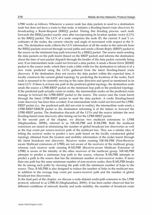


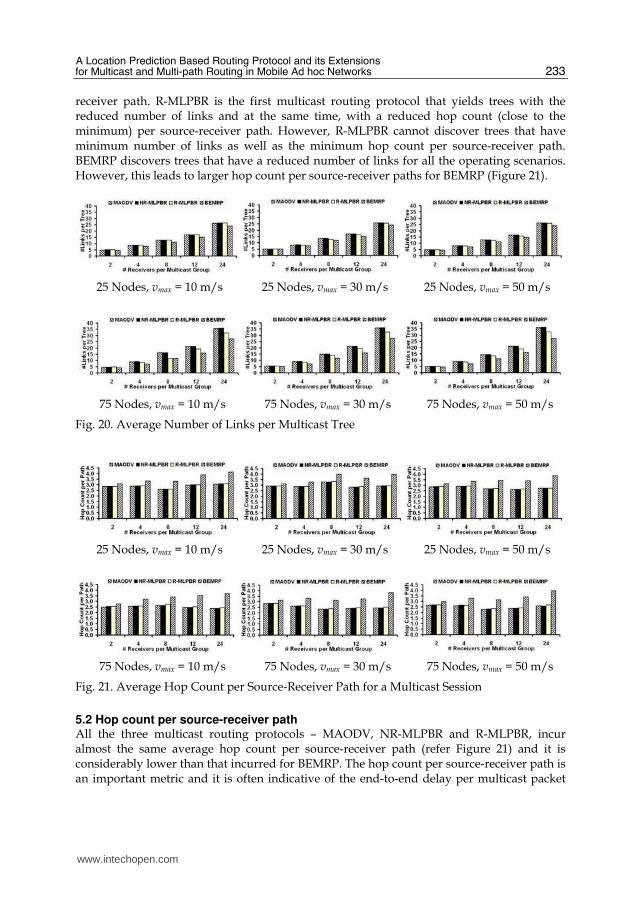


![A Novel Hybrid Routing Protocol for Mobile Adhoc Network · A Novel Hybrid Routing Protocol for Mobile Adhoc Network ... routing overhead, ... Reactive routing protocol [2, 8, 9]](https://static.documents.pub/doc/80x56/5ac806c47f8b9a42358bf340/a-novel-hybrid-routing-protocol-for-mobile-adhoc-network-novel-hybrid-routing-protocol.jpg)


