62:1 (2013) 1–8 | www.jurnalteknologi.utm.my | eISSN 2180–3722 | ISSN 0127–9696
Full paper Jurnal
Teknologi
A Low Cost Stirring Platform with Integrated Temperature Control Scheme for Microbioreactor Operation Hazwan Halimoon
a, Muhd Nazrul Hisham Zainal Alam
b*
aDepartment of Bioprocess Engineering, Faculty of Chemical Engineering, Universiti Teknologi Malaysia, 81310 UTM Johor Bahru, Johor, Malaysia bProcess Systems Engineering Centre, Faculty of Chemical Engineering, Universiti Teknologi Malaysia, 81310 UTM Johor Bahru, Johor, Malaysia *Corresponding author: [email protected]
Article history
Received :3 December 2012
Received in revised form :
18 February 2013
Accepted :15 April 2013
Graphical abstract
Abstract
In this paper, we presented the establishment of a cheap and simple stirring platform integrated with on/off
temperature controller for microbioreactor operation. The stirring platform was designed to provide
necessary mixing via magnetic stirrer bar for a microbioreactor setup. The microbioreactor (volume ~ 300
microliter) used in this investigation was fabricated out of the poly(methylmethacrylate) (PMMA) polymer material via micromachining. The reactor was deliberately designed to work under bubble-free
conditions and limited only to batch operation. The paper first described the details of the mechanical
design of the stirring platform and the microbioreactor prototype used in the work. These include the dimensions of the reactor and the stirring platform, positioning of the sensors and actuators employed,
wiring connections, and the process control algorithm. Secondly, experimental results obtained to assess
the mixing quality of the reactor and to characterize the performance of the controller (stirring and temperature) in terms of control accuracy and system responses were presented. We show that by
implementing a rather straight forward control algorithm, the mixing quality and the temperature of the
microbioreactor can be accurately controlled within an acceptable range of the set point values and provide a good response (i.e. in the range of few seconds). Results also showed that (1) at agitation rate of
300 rpm, mixing time as fast as 3 seconds was obtained and (2) reactor temperature can be tightly
controlled at ±0.15 oC of the set point value.
Keywords : Microbioreactors; mixing, process automation; temperature control and micro-stirrer bar
Abstrak Dalam kertas kerja ini, penghasilan pelantar pengadukan integrasi bersama sistem kawalan suhu
buku/tutup untuk operasi mikrobioreaktor ditunjukkan. Pelantar pengadukan ini direkabentuk untuk
menyediakan operasi pengadukan dengan menggunakan pengaduk magnet mikro bagi sistem mikrobioreaktor. Mickrobioreaktor (isipadu ~ 300 microliter) yang digunakan dalam ujikaji ini telah
diperbuat daripada bahan polimer poly(methylmethacrylate) (PMMA) secara pembuatan-mikro. Reaktor
tersebut direkabentuk untuk digunakan dalam keadaan bebas-buih dan terhad pada operasi berpukal sahaja. Kertas kerja ini pertamanya akan menerangkan tentang rekabentuk mekanikal pelantar pengadukan
dan prototaip mikrobioreaktor yang digunakan dalam ujikaji ini. Ini termasuk dimensi reactor dan pelantar
pengadukan, perletakkan pengesan-pengesan dan penggerak-penggerak, penyambungan wayar, dan algoritma proses kawalan. Keduanya, keputusan-keputusan eksperimen yang diperolehi untuk menilai
kualiti pengadukan dan untuk menguji keberkesanan unit kawalan (pengadukan dan suhu) dari segi
ketepatan kawalan, dan tindakbalas unit kawalan akan ditunjukkan. Kami tunjukkan bahawa dengan menggunakan algoritma kawalan yang yang mudah, kualiti pengadukan dan suhu mikrobioreaktor boleh
dikawal dengan tepatnya dalam lingkungan yang boleh diterima dan memberikan tindakbalas yang bagus
(iaitu dalam lingkungan beberapa saat). Keputusan menunjukkan bahawa (1) pada kadar pengadukan 300 rpm, masa pencampuran sepantas 3 s diperolehi dan (2) suhu reactor boleh dikawal dengan rapatnya pada
±0.15 oC daripada nilai yang disasarkan.
Kata kunci: Mikrobioreaktor; pengadukan; proses automasi; kawalan suhu dan pengaduk magnet mikro
© 2013 Penerbit UTM Press. All rights reserved.
1.0 INTRODUCTION
Microbioreactors are miniature size reactor system that generally
fabricated to facilitate studies associated with bioprocessing e.g.
fermentation experiments to screen for optimal growth conditions
for cells [1-3], assessing novel enzyme processes [4-6], etc.
Microbioreactors are indeed a new emerging technology and have
been receiving increasing attention from the academia and
2 Hazwan & Muhd Nazrul Hisham / Jurnal Teknologi (Sciences & Engineering) 62:1 (2013), 1–8
industry due to their numerous advantages in assessing biological
processes. These include significant reduction in substrates
consumption due to small working volumes (i.e. less than 1
milliliter), high throughput, remarkably fast mass and heat
transfer rates, rich-information system and offer a good process
control capabilities comparable to the bench scale bioreactor
systems [7].
In microbioreactor operation, a good mixing scheme is
imperative for (1) the transport and/or homogenous mixing of
nutrients and substrates (e.g. oxygen, carbon sources, etc.), (2)
keeping cells in suspension and finally, (3) to promote adequate
mass and heat transfer rates through-out the reactor. Hence,
allowing the system to handle a larger amount of biomass with
increased reaction rates [7]. On a standard bench scale bioreactor
system, intense mixing is normally applied to achieve necessary
turbulence conditions (i.e. NRe > 2000) for a good mixing [8]. On
contrary, in a microliter scale operation, due to the low Reynolds
number; liquid motion in the reactor is always in the laminar flow
regime (i.e. NRe < 100) [7,9] and often relies on the molecular
diffusion rather than turbulence. Mixing in this state is terribly
slow and inefficient. Therefore, alternatives to improve mixing
condition in such a small reactor system are generally aimed at
increasing the contact/interfacial area and/or reduce the diffusion
lengths between two or more fluids [7,9].
Mixing in microbioreactors can be achieved by either passive
mixing or active mixing schemes [7]. Table 1 shows advantages
and disadvantages of various types of mixing schemes that have
been implemented in the microbioreactor world to provide
sufficient mixing for microbioreactor operation. In passive (or
static) mixing schemes, no moving parts are applied and mixing is
achieved by pumping the reactor content through a well-
structured groove that is normally machined into a shallow
microchannel. During mixing, fluid streams are repeatedly split
and combined along the microchannel to achieve a homogenous
mixing [10]. Indeed, seemingly like a viable solution but
necessary three-dimensional microstructures for a sufficient
mixing e.g. the staggered herringbone mixer [10] can be
extremely difficult to fabricate. Moreover, such passive method
does not guarantee that the cells will be in suspension state during
operation. In the active mixing schemes, moving parts (e.g. orbital
shaker [11], magnetic stirrer bar [1,3,5,9,12], micropumps and
microvalves [2], syringe pump [13], etc.) are normally utilized for
mixing of the reactor content. Active mixing schemes can be
activated on demand and generally deployed to induce mixing
inside the microbioreactor reaction chamber.
Table 1 Advantages and disadvantages for different mixing scheme options for microbioreactor operation
Mixing schemes Types Advantages Disadvantages
Passive
T/Y shape and
serpent-like mixers [4]
Easy to fabricate
Simple reactor design
No moving parts
Continuous operation: possible
Pump needed
Less effective for viscous medium
Microchannel can be excessively long
Parallel operation: costly if external pumps
are used
Staggered
herringbone
mixer [10]
Simple reactor design
No moving parts
Shorten microchannel’s length for mixing
Continuous operation: possible
Difficult to fabricate
Difficult to scale-up
Pump needed
Parallel operation: costly if external pumps are used
Active
Shaker [11] Simple solution for lab
Parallel operation: possible (i.e. if user satisfied with the same mixing speed for every reactors)
Not feasible for reactor with no headspace
(i.e. induce little mixing)
Batch operation only
Impossible to scale-up
Magnetic stirrer bar [1,3,5,9,12]
Better for viscous medium
Prevent any dead zones
Easy to scale-up
Continuous operation: possible
Simple reactor design
Parallel operation: costly (i.e. magnetic stirrer for each reactor)
Difficult to fabricate stirrer bar (except for the commercial ones)
High velocity
recirculation
flow [2]
Simple reactor design
Continuous operation: possible
High recycle flow improved mixing
Pump needed
Slow mixing in the tubes
Complex fluidic connections for parallel
operation
Air cushions [13] Parallel operation: possible at different mixing speed
Prevent any dead zones
Continuous operation: possible
Difficult to fabricate
Difficult to scale-up
One of the most commonly used active mixing methods for
mixing in microbioreactor operation is the use a magnetic stirrer
bar [1,3,5,9,12]. In the microbioreactor design of Zhang et al.
[9], a ring-shape magnetic stirrer bar (6 mm arm length, 0.5 mm
diameter) was fabricated and mounted on a hub (i.e. a rigid
vertical post) for a steady mixing on a fixed rotational axis.
Whilst this system creates defined liquid movement in the
reaction chamber volume, it suffers from a couple of drawbacks
3 Hazwan & Muhd Nazrul Hisham / Jurnal Teknologi (Sciences & Engineering) 62:1 (2013), 1–8
as well. First, both the stirrer bar as well as the hub needed to
mount the impeller requires a precise fabrication which can be
complicated and secondly, it cannot guarantee that there are no
dead zones in the reactor: the corners between the vertical walls
and the horizontal floor are typically the most critical point [7].
An alternative solution and perhaps a simpler approach is to use
a commercially available micro magnetic stirrer bar [5,12].
Zainal Alam et al. [5] and Schäpper et al. [12] used a micro
magnetic stirrer bar (3 mm length, 1.2 mm diameter, Sigma) and
actuated it above a magnetic stirrer platform to create a random
chaotic motion inside the reactor chamber. Thus, eliminates any
possible dead zones whilst keeping the microbial cells in
suspension. Since the magnetic stirrer bar is not mounted on any
hub, it often hits the reactor walls and bounce back to the center
of the reactor chamber in an irregular pattern. This makes it
rather difficult to simulate with standard engineering software
e.g. COMSOL, Fluent, etc. for optimization purposes. In any
case, the use of magnetic stirrer bar is truly advantageous as it
could create an intense local mixing and provides the necessary
updraft lifting force to keep the microbial cells in suspension.
Intense mixing created larger interfacial area and increase
contact times for mixing. Reactor design is also simpler [5,9,12]
and hence; minimize the reactor fabrication steps required.
In this paper, we presented the establishment of a low cost
and simple stirring platform with integrated temperature control
scheme for microbioreactor operation. The stirring platform was
designed to provide necessary mixing via magnetic stirrer bar
with inclusion of a cheap temperature control scheme for a
microbioreactor setup. In our application we aimed at
developing disposable single-use microbioreactors with minimal
or no electrical connections on the single-use part of the reactor.
Thus, keeping a low fabrication cost and decreasing the risk of
handling errors during starting-up of the microbioreactor
operation. The paper first described the details of the
mechanical design of the stirring platform and the
microbioreactor prototype used in the work. These include the
dimensions of the reactor and the stirring platform, positioning
of the sensors and actuators employed, wiring connections, and
the process control algorithm. Secondly, experimental results
obtained to assess the mixing quality of the reactor and to
characterize the performance of the controller in terms of
control accuracy and system responses were presented.
2.0 MATERIALS AND METHODS
2.1 Microbioreactor Design and Fabrication
The microbioreactor prototype presented in this work was
fabricated specifically to facilitate two different types of
experiments. The reactor was used (1) to assess the mixing
quality of the reactor and (2) to evaluate the workability of the
integrated temperature control scheme. It was designed to work
with constant working volume, with no head space and under
bubble-free conditions.
The prototype (Figure 1a) consisted of a reaction chamber
(centered in the middle of the reactor) and a trapezoid shape side
stand. The reaction chamber has a depth of 2.5 mm and a
diameter of 12 mm, giving a volume of about 300 microliter.
The bottom of the reaction chamber was covered by a thin
poly(methylmethacrylate) (PMMA) layer (thickness ~ 0.5 mm)
where else the top of the reaction chamber was left open. A
magnetic stirrer bar with a length of 7 mm and thickness of 2
mm was placed on the reactor’s floor for mixing. The side wall
of the prototype was extended into a trapezoid shape side stand
(thickness = 1 mm and surface area ~ 132 mm2) to keep the
reactor in balance (i.e. rigid position) during operation. In this
prototype, there are neither microchannels nor additional ports
for loading of the reactor content. The reactor content was filled
by injecting a known amount of desired working solution from
the top of the reactor which is already-opened. The reactor
design was kept simple as (1) it will only be used for a proof-of-
concept study and, (2) to minimize the fabrication steps needed.
The prototype was completely made of
poly(methylmethacrylate) (PMMA) and was fabricated by using
computer-numerical-controlled (CNC) milling machine (MDX-
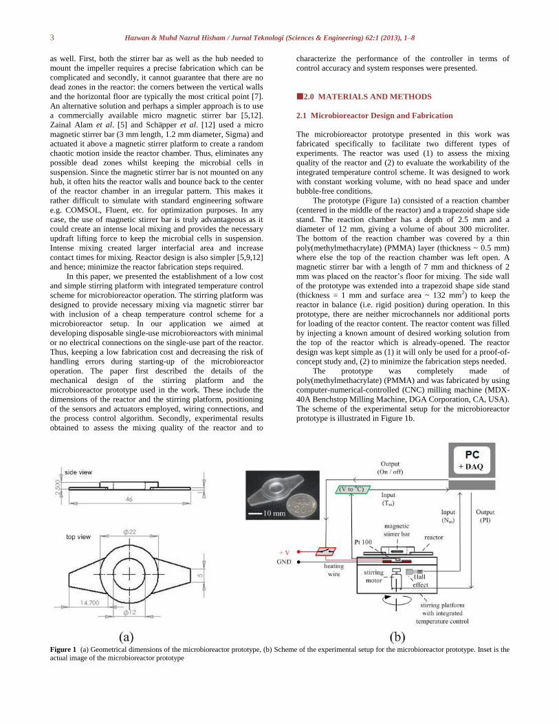
40A Benchstop Milling Machine, DGA Corporation, CA, USA).
The scheme of the experimental setup for the microbioreactor
prototype is illustrated in Figure 1b.
Figure 1 (a) Geometrical dimensions of the microbioreactor prototype, (b) Scheme of the experimental setup for the microbioreactor prototype. Inset is the
actual image of the microbioreactor prototype
4 Hazwan & Muhd Nazrul Hisham / Jurnal Teknologi (Sciences & Engineering) 62:1 (2013), 1–8
2.2 Stirring Platform: Mechanical Design
A cheap stirring platform with integrated temperature control
scheme was customized to provide necessary mixing and
temperature control capacity for the microbioreactor prototype
(Figure 2a). For this purpose, a 12 cm (length) x 8 cm (width) x
5 cm (thickness) Polyvinyl chloride (PVC) housing was utilized.
The platform was designed as a modular component containing
a magnetic stirrer (built in inside the PVC housing) and a
temperature controller plate (fixed via screws on the top of the
PVC housing).
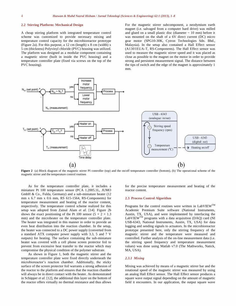
For the magnetic stirrer subcomponent, a neodymium earth
magnet (i.e. salvaged from a computer hard drive) was milled
and glued on a small plastic disc (diameter ~ 10 mm) before it
was mounted on the shaft of a 6V direct current (DC) micro
gear motor (SPG10-30K, Cytron Technologies Sdn. Bhd.,
Malaysia). In the setup also contained a Hall Effect sensor
(A1301EUA-T, RS-Components). The Hall Effect sensor was
used to measure the magnetic stirrer speed and it was placed as
close as possible to the magnet on the motor in order to provide
strong and persistent measurement signal. The distance between
the tips of switch and the edge of the magnet is approximately 1
mm.
Figure 2 (a) Block diagram of the magnetic stirrer PI controller (top) and the on/off temperature controller (bottom), (b) The operational scheme of the
magnetic stirrer and the temperature control routines
As for the temperature controller plate, it includes a
miniature Pt 100 temperature sensor (PCA 1.2005.1L, JUMO
GmbH & Co., Fulda, Germany) and a sub-miniature heater (12
mm x 6.7 mm x 0.6 mm, RS 615-1564, RS-Components) for
temperature measurement and heating of the reactor content,
respectively. The temperature control scheme realized for this
setup was adopted from Zainal Alam et al. [14]. Figure 2b
shows the exact positioning of the Pt 100 sensor (5 × 2 × 1.3
mm) and the microheater on the temperature controller plate.
The heater was integrated in this manner in order to provide an
even heat distribution into the reaction chamber. In the setup,
the heater was connected to a DC power supply (converted from
a standard ATX computer power supply with 3.3, 5 and 7 V
outputs) for heating. The surface containing the sub-miniature
heater was covered with a cell phone screen protector foil to
prevent from excessive heat transfer to the reactor which may
compromise the physical condition of the polymer substrate.
As shown in Figure 1, both the magnetic stirrer and the
temperature controller plate were fixed directly underneath the
microbioreactor’s reaction chamber. Additionally, the sticky
surface of the screen protector foil warrants a strong adhesion of
the reactor to the platform and ensures that the reaction chamber
will always be in direct contact with the heater. As demonstrated
in Schäpper et al. [12], the additional thin layer on the bottom of
the reactor offers virtually no thermal resistance and thus allows
for the precise temperature measurement and heating of the
reactor content.
2.3 Process Control Algorithm
Programs for the control routines were written in LabVIEWTM
Academic Premium Suite software (National Instruments,
Austin, TX, USA), and were implemented by interfacing the
LabVIEWTM programs with a data acquisition (DAQ) card (NI
USB-6343, National Instruments, Austin, TX, USA) for data
logging and sending signals to actuators. In the microbioreactor
prototype presented here, only the stirring frequency of the
magnetic stirrer and the temperature were measured and
controlled. Further analysis of the on-line measurement data (i.e.
the stirring speed frequency and temperature measurement
values) was done using Matlab v7.0 (The Mathworks, Natick,
MA, USA).
2.3.1 Mixing
Mixing was achieved by means of a magnetic stirrer bar and the
rotational speed of the magnetic stirrer was measured by using
an analog Hall Effect sensor. The Hall Effect sensor produces a
square wave output signal depending on the amount of magnetic
field it encounters. In our application, the output square wave
5 Hazwan & Muhd Nazrul Hisham / Jurnal Teknologi (Sciences & Engineering) 62:1 (2013), 1–8
signal of the Hall Effect sensor was based on the number of
passes made by the magnetic stirrer i.e. in revolution per minute
(rpm). Sampling frequency used to obtain the square wave
signal (via LabVIEW) was 1500 Hz (samples per second).
Additionally; the square wave pulses generated by the Hall
Effect sensor were confirmed by using an oscilloscope (data not
shown). The magnetic stirrer stirring frequency was adjusted
(i.e. either increase or decrease of stirring frequency) by a
proportional-integral (PI) control algorithm whose error signal
was based on the deviation between the measured and the
desired stirring frequency values (Figure 2a). A power transistor
was connected between the DC power supply and the DC motor
to amplify the analog output signal from the DAQ as the analog
outputs do supply enough current to drive the DC motor during
operation. The magnetic stirrer PI controller was tuned using the
Ziegler-Nichols tuning method [15]. A set point tracking
experiment was also performed to assess the performance of the
PI controller based on its accuracy, response time and settling
time.
2.3.2 Temperature control
The temperature of the reactor content was controlled by an
on/off controller which was adopted from Zainal Alam et al.
[14]. The operation of the temperature controller is presented in
Figure 2a. In this feedback temperature controller, analog
voltage signals received from the temperature sensor (Pt 100)
were linearized and converted to temperature values (oC) via a
transmitter (JUMO dTRANS T04, JUMO GmbH & Co., Fulda,
Germany). Deviation (error) between the desired set point value
Tsp and the measured value Tm will then be computed by
LabVIEW program. Heating will only be activated if the Tm
value goes below the desired Tsp value (i.e. if the error is
positive, Tsp > Tm), else the heater will remain in off state.
Heating is achieved by passing an electrical current at fixed
voltage supply through the resistance wire embedded on the
stirring platform. A latching relay was used to connect the DC
power supply to the heating wire for heating. A 1 s delay was
introduced in the routine to prevent rapid switching of the relay
output [14]. The on/off temperature control scheme was tuned
by applying various power inputs (i.e. at 3.3, 5 and 7 V) at
different temperature set point values between 25oC and 50oC.
The tuning step was necessary to achieve optimal on/off
controller settings (good accuracy and fast response).
Both of the control routines presented here were set to
operate sequentially in continuous loop where it involves the use
of analog in-/output (AI/AO) channels and digital output
channel of the DAQ card. The operational scheme of the
LabVIEW program is presented in Figure 2b. The LabVIEW
program was initiated by first performing the measurement and
control of the magnetic stirring frequency via the AI/AO ports.
In sequence, the program then read the temperature
measurement data through a different AI port and gives out the
resulting digital output value for the temperature control part.
The routine was then looped back to the first step to repeat the
whole cycle again. One complete cycle runs for approximately 3
s before restarting (excluding the time consumed for heating).
All experiments were repeated twice to check data
reproducibility.
2.4 Mixing Test: Fluorescent Dye Visualization Technique
The mixing quality of our microbioreactor prototype was
assessed using the fluorescent dye visualization technique [5].
The experiment was performed by first filling the reactor with
the desired working solution, which was then followed by
adding a drop of fluorescent solution (prepared by diluting a
concentrated fluorescein green solution with distilled water at
mixing ratio 1:1) with a syringe. Mixing effects were observed
and images of dispersion of the fluorescent solution in the
reactor were recorded by a digital camera (Nikon D90, Nikon
Corporation, Japan). Mixing time was estimated at various
agitation rates (i.e. at 100 rpm, 200 rpm and 300 rpm) by using
water as the model solution. Duplicates were made for each
condition tested. Mixing time was recorded as the time for the
fluorescent dye to be completely dispersed.
A rather straight forward image analysis was also
performed to graphically assess the homogeneity of the reactor
content at various mixing conditions. Recorded images were
uploaded and analyzed via ImageJ software (Wayne Rasband,
National Institute of Health, USA) [16]. Analysis was based on
the difference between the background colour and the colour
intensity of the concentrated dye injected into the
microbioreactor chamber. The colour difference was computed
and the homogeneity level in the microbioreactor chamber was
represented as total area covered by the concentrated dye (i.e.
percentage area covered).
3.0 RESULTS AND DISCUSSIONS
3.1 Controller Performance
Figure 3 shows the response of the microbioreactor PI stirring
controller and the on/off temperature controller for a series of
step changes in the agitation and temperature set point values,
respectively. For the PI stirring controller, the agitation rate, N
(rpm) was raised from an off-state condition (i.e. initial
condition at zero voltage supply) until it reached the agitation
rate, N of approximately 600 rpm which is the maximum speed
achievable by the DC motor used in this microbioreactor setup.
As previously mentioned, the controller was tuned according to
the Ziegler-Nichols tuning method. The controller constants
attained were 0.3 and 0.017 for the proportional, Kc and integral,
Ti constants, respectively. Since a readily available sub-VI (a
sub program attained from the LabVIEW software library) for
the PI stirring controller was used, the controller constants can
also be automatically adjusted and/or refined to give better
approximations of the PI stirring controller i.e. if needed so.
Based on the data obtained (Figure 3a), it was found that the PI
controller responded nearly instantaneously in every step change
applied with a recorded response time of about 0.001 ms. A
slight overshoot and/or undershoot (~2 rpm from the set point
values) with settling time of approximately 8 s when increasing
and/or decreasing the agitation rate are expected behavior for
such PI controller. As presented in Figure 3a, the accuracy
attained for the PI stirring controller was + 1 rpm of the set point
value. For the on/off temperature controller, the controller was
tuned to operate at heater pulse length of 1 s and connected to
voltage supply of 5 V. It was found that by implementing such
settings the temperature can be controlled to within ±0.15 oC of
the set point value. This is illustrated in Figure 3b. Moreover, no
delay was observed when regulating the temperature set point
values from one set point to another. This is mostly due to the
high surface to volume ratio, S/V (1100 m-1) of the
microbioreactor which facilitates a fast thermal response. The
fluctuating measured signal (as seen in Figure 3b) is a typical
behavior of the on/off controller. The heating rate and the
cooling rate of the reactor were calculated to be 0.36 oC·s-1 and
0.16 oC·s-1, respectively. The cooling step was rather slow
compared to the heating capacity of the controller as there is no
cooling element was realized in the setup and cooling was
6 Hazwan & Muhd Nazrul Hisham / Jurnal Teknologi (Sciences & Engineering) 62:1 (2013), 1–8
merely depends on heat dissipation to the surroundings.
Eventually, room temperature will be reached asymptotically as
the driving force is the temperature difference itself. Our results
are consistent with what have been reported by Zainal Alam et
el. [14].
Figure 3 Figure 3. Response of the microbioreactor PI stirring controller (left) and on/off temperature controller (right) for a series of step changes in the
agitation and temperature set point values, respectively
3.2 Mixing Quality And Homogeneity
The mixing quality of the microbioreactor was evaluated by
using a simple tracer method i.e. by visualizing the dispersion
rate of a very small amount of concentrated fluorescent solution.
Such method enabled us to visualize the mixing pattern inside
the reactor and predict the mixing time at various agitation rates.
Results obtained from the mixing test experimentation are
depicted in Figure 4. Based on the time-course images in Figure
4, it can be seen that the fluorescent solution immediately
unwound and disperse uniformly throughout the reaction
chamber due to the stirring action of the magnetic stirrer bar.
Regardless of the agitation rate applied, uniform color
distribution was eventually obtained after a certain period of
time. The obvious concentration difference between the
concentrated fluorescent solution and the mother solution
(water) led to diffusion of the concentrated dye into other
regions within the reaction chamber where else the vigorous
stirring action of the magnetic stirrer bar breaks the concentrated
dye to create larger interfacial area for mixing. A longer mixing
time was recorded for slower agitation rate i.e. at N=100 rpm
mixing time is approximately 33 s but at higher agitation rate
(i.e. at N=300 rpm), the mixing accelerated and a mixing time of
about 3 s was recorded. A faster mixing was achieved at higher
agitation rates because at increasing rates, the degree of local
turbulence also increases which promotes better mixing. The
degree of local turbulence was represented by the Reynolds
number, NRE. Reynolds number can be defined as a
dimensionless number of that gives a measure of the degree of
turbulence in a confined space [17]. It was found that the
turbulence conditions within the microbioreactor reaction
chamber was shifting from laminar flow regime (NRE = 81) to
transition phase (NRE = 245) when the agitation rate was
increased from N=100 rpm to N=300 rpm, respectively. Results
attained in this study are comparable with data from published
investigations on mixing in microbioreactor setup via magnetic
stirrer bar. Zhang et al. [9], integrated a ring-shape magnetic
stirrer bar (6 mm arm length, 0.5 mm diameter) and a mixing
time of 30 s was achieved when operating at agitation rate, N of
180 rpm (the microbioreactor volume was 150 microliter. Zainal
Alam et al. [5] used a commercial magnetic stirrer bar (3 mm
length, 1.2 mm diameter, Sigma) to stir a sugar beet pectin
solution (solution concentration = 10 g/L) and uniformity was
obtained in less than 30 s when operated at agitation rate, N of
500 rpm (the microbioreactor volume was 200 microliter).
Similarly in Schäpper et al. [12], a commercial magnetic stirrer
bar (3 mm length, 1.2 mm diameter, Sigma) was used and a
complete mixing was observed after 1.2 s (the microbioreactor
volume was 100 microliter).
Figure 4 Images of mixing of the fluorescent dye solution in the microbioreactor at various stirring speed i.e. top: N =100 rpm (NRE=
81), middle: N=200 rpm (NRE= 163) and bottom: N=300 rpm (NRE=
245). Arrows indicate the point of injection
7 Hazwan & Muhd Nazrul Hisham / Jurnal Teknologi (Sciences & Engineering) 62:1 (2013), 1–8
From the results in Figure 4, uniform colour distribution
seemingly indicated that the reactor content was well-mixed
without any “dead zones”. However, to confirm this, we
assessed the quality of the image by using the graphical analysis
software (ImageJ software, Wayne Rasband, National Institute
of Health, USA) [16]. If the homogeneity level is approximately
or greater than 95% (i.e. based on the difference of colour
intensity), it can be assumed that a well-mixed condition was
successfully achieved. This was however not the case in our
microbioreactor setup when the agitation rate was set at stirring
speed 200 rpm and below (Figure 5). At this condition, the
reactor content was only 80-85% homogenous. As evident in
Figure 5c, a nearly perfect homogenous solution was
sufficiently obtained when operating at agitation rate of 300
rpm. The results further suggested that for our microbioreactor
operation, conducting the microbioreactor experiments at
agitation rate in the range between 300 rpm to 400 rpm is
sufficient to achieve a good and the necessary homogenous
reactor content. Although the micro magnetic stirrer bar was not
attached to a fixed axis and rotating in an irregular movement, it
did not create any limitations for our microbioreactor operation.
On contrary, it seems that such irregular rotating motion
eliminates the unnecessary ‘dead-zones’ within the
microbioreactor chamber particularly on the edge and corners of
the reaction chamber walls.
Figure 5 Results of image analysis representing the level of homogeneity of the microbioreactor content at various stirring speed i.e. (a) N=100 rpm (NRE=
81),. (b) N=200 rpm (NRE= 163) and (c) N=300 rpm (NRE= 245). Dashed red lines representing the level of homogeneity achieved at given conditions and inset illustrates the final state of the reactor content
Figure 6 Picture of the actual microbioreactor setup established in the Process Systems Engineering Centre (PROSPECT), UTM hands-on laboratory
3.3 Practical Feasibility Of The Microbioreactor Setup
The whole idea of the work was to fabricate a low cost and
feasible operating gear for the microbioreactor operation. In our
microbioreactor system, the plan was to keep the microbireactor
design as simple as possible and separate the essential sensors
and actuators to control the microbioreactor operation on a
separate platform. As a separate unit made completely from a
cheap poly(methylmethacrylate) (PMMA) polymer that featured
only a reaction chamber and a micro magnetic stirrer bar; the
microbioreactor can definitely be made disposable.
Additionally, the microbioreactor would be easy-to-handle as no
cleaning nor sterilization steps needed when starting new
experiment.
The operating platform was customized by using parts and
electronic components that are commercially available
inexpensively in any hardware and/or electronic store. The
capital cost was approximately 100-125 € / setup. Despite its
simplicity, the operating platform allows users to vary the
agitation and the temperature set point values accordingly. The
agitation rate can be adjusted by changing the frequency of the
DC motor (possible operating range between 0 to 600 rpm) and
the temperature of the reactor content can be varied by
controlling the on/off pulse length of the micro-heater (possible
range between room temperature and 50oC). Such flexibility
provides one to carry out experimentation and/or investigations
by using the microbioreactor setup at various experimental
conditions. The microbioreactor at its current state is only
suitable to cater batch biocatalyst processes under buffered
8 Hazwan & Muhd Nazrul Hisham / Jurnal Teknologi (Sciences & Engineering) 62:1 (2013), 1–8
conditions. Surely, future improvements is needed e.g.
integration of on line UV detection method, dissolved oxygen
control, etc., such that the microbioreactor setup can also be
used to carry out fermentation experiments. Based on the
experimental results (Figure 3 and Figure 4), fast mass and heat
transfer rates i.e. in the range of few seconds demonstrated the
main advantage of conducting experimentation in sub-milliliter
range. The only minor drawback for our setup is the bulky and
the expensive National Instruments (NI) data acquisition card
(DAQ) for execution of the process control routines. The unit is
however imperative for the microbioreactor operation and a
cheaper NI data acquisition cards are also available which could
perform similarly to what was used in this microbioreactor setup
i.e. the NI USB 6343 (Figure 6).
4.0 CONCLUSIONS
A cheap and simple stirring platform integrated with on/off
temperature controller for microbioreactor operation was
developed. The microbioreactor prototype was fabricated from
poly(methylmethacrylate) (PMMA) polymer and separated from
the stirring platform. This was deliberate as the plan was to
bring forth the single-use (i.e. disposable) microbioreactor
concept. It was demonstrated that the set point values for the
agitation rate and the reactor temperature can be precisely
controlled within acceptable range of the set point values. The
controller is also user-friendly as to operate the microbioreactor
system, one need only to adjust the frequency of the DC motor
for mixing and vary the heating pulse length for the temperature
control. Further improvements are necessary in order to push the
capacity of the microbioreactor technology such that it can
facilitate fermentation experiments rather than limiting its
usefulness only for biocatalyst processes.
Acknowledgement
We would like to express our gratitude to Malaysia Ministry of
Higher Education (MOHE) and Universiti Teknologi Malaysia
for funding the project. The project was funded by Research
University Potential Academic Grant Scheme (PAS) (vote
number, 05J26). Special thanks also to Abdul Muim Abdul
Nasir for providing help with the experimentation.
\
References
[1] Szita, N., Bocazzi, P., Zhang, Z., Boyle, P., Sinskey, A. J., and Jensen,
K. F. 2005. Development of a Multiplexed Microbioreactor System
for High-throughput Bioprocessing. Lab on a Chip. 5: 819–826.
[2] Lee, H. L., Bocazzi, P., Ram, R. J., and Sinskey, A. J. 2006.
Microbioreactor Arrays with Integrated Mixers wnd Fluid Injectors for High Throughput Experimentation with Ph And Dissolved
Oxygen Control. Lab on a Chip. 6: 1229–1235.
[3] Zhang, Z., Perozziello, G., Boccazzi, P., Sinskey, A. J., Geschke, O.
and Jensen, K. F. 2007. Microbioreactors for Bioprocess
Development. Association for Laboratory Automation. 12: 143–151.
[4] Swarts, J. W., Vossenberg, P., Meerman, M. H., Janssen, A. E. M. and
Boom, R. M. 2008. Comparison of Two-phase Lipase-catalyzed
Esterification on Micro and Bench Scale. Biotechnology and Bioengineering. 99: 855–861.
[5] Zainal Alam, M. N. H., Pinelo, M., Samantha, K., Jonsson, G., Meyer,
A., and Gernaey, K. V. 2010. A Continuous Membrane
Microbioreactor System for Development of Integrated Pectin
Modification and Separation Processes. Chemical Engineering
Journal. 167: 418–426.
[6] Pohar, A., Znidarsic-Plazl, P., and Plazl, I. 2012. Integrated System of
a Microbioreactor and a Miniaturized Continuous Separator for Enzyme Catalyzed Reactions. Chemical Engineering Journal. 189–
190: 376–382.
[7] Schäpper, D., Zainal Alam, M. N. H., Szita, N., Lantz, A. E.,
Gernaey, K. V. 2009. Application of Microbioreactors in
Fermentation Process Development: A Review. Analytical and
Bioanalytical Chemistry. 395: 679–695.
[8] Shuler, M. L. and Kargi, F. 2002. Bioprocess Engineering: Basic Concepts. 2nd ed. Prentice Hall, New Jersey, US. 292–296.
[9] Zhang, Z., Szita, N., Boccazzi, G., Sinskey, A. J. and Jensen, K. F.
2005. A Well-mixed, Polymer-based Microbioreactor with Integrated
Optical Measurements. Biotechnology and Bioengineering. 93: 287–
296.
[10] Strook, A. D., Dertinger, S. K. W., Ajdari, A., Mezić, I., Stone, H. A.
and Whitesides, G. M. 2002. Chaotic Mixer for Microchannels.
Science. 295:647–651. [11] Wen, Y., Zang, R., Zhang, X., and Yang, S. 2012. A 24-microwell
Plate with Improved Mixing and Scalable Performance for High
Throughput Cell Cultures. Process Biochemistry. 47: 612–617.
[12] Schäpper, D., Stocks, S. M., Szita, N., Lantz, A. E., and Gernaey, K.
V. 2010. Development of a Single-use Microbioreactor for
Cultivation of Microorganisms. Chemical Engineering Journal. 160:
891–898. [13] Li, X., van der Steen, G., van Dedem, G. W. K., van der Wielen, L. A.
M., van Leeuwen, M., van Gulik, W. M., Heijnen, J. J.,
Krommenhoek, E. E., Gardeniers, J. G. E., van den Berg, A. and
Ottens, M. 2008. Improving Mixing in Microbioreactors. Chemical
Engineering Science. 63: 3036–3046.
[14] Zainal Alam, M. N. H., Schäpper, D., and Gernaey, K. V. 2010.
Embedded Resistance Wire as Heating Element for Temperature
Control in Microbioreactors. Journal of Micromechanics and Microengineering. DOI: 10.1088/0960-1317/20/5 /055014.
[15] Seborg, D. E., Edgar, T. F., and Mellichamp, D. A. 2004. Process
Dynamics and Control. 2nd ed. New Jersey: John Wiley & Sons, Inc.
317–320.
[16] Collins, T. J. 2007. ImageJ for Microscopy. BioTechniques. 43(1
Suppl): 25–30. doi:10.2144/000112517.
[17] Bailey, J. F., and Ollis, D. F. 1986. Biochemical Engineering
Fundamentals. 2nd ed. Mc-Graw Hill, New York, US
.