Automated 3D Printer Farm A Major Qualifying Project submitted to the Faculty of the WORCESTER POLYTECHNIC INSTITUTE in partial fulfillment of the requirements for the Degree of Bachelor of Science By: Dasan E. Costandi - Robotics Engineering Lauren N. Pontbriant - Robotics Engineering Alexander N. Ruggiero - Robotics Engineering Kevin A. Valente-Comas - Robotics Engineering Project Advisor: Professor Craig Putnam Date: 04/20/17
Transcript
Automated 3D Printer Farm
A Major Qualifying Project submitted to the Faculty
of the WORCESTER POLYTECHNIC INSTITUTE
in partial fulfillment of the requirements for the Degree of Bachelor of Science
By:
Dasan E. Costandi - Robotics Engineering Lauren N. Pontbriant - Robotics Engineering
Alexander N. Ruggiero - Robotics Engineering Kevin A. Valente-Comas - Robotics Engineering
Project Advisor: Professor Craig Putnam
Date:
04/20/17
Abstract Automation can be applied to many different disciplines including 3D printing. This project applies automation to a 3D printer farm with the goal of removing the need for human interactions. The robot incorporated into the system, the Fanuc 200iB, is used for removing the plates from the printer, placing completed prints onto a cooling rack and placing new plates onto the printer. A management system consisting of an Arduino, a Raspberry Pi and a Repetier server is used for coordinating the movements of system elements.
1
Table of Contents 1. Introduction……………………………………………………………………………………..5
1.1 3D Printer Farm…………………………………………………………………………...6 1.2 Intended Use……………………………………………………………………………....6
2. Background…………………………………………………………………………………….7 2.1 Origins of 3D Printing……………………………………………………………………..7 2.2 3D Printing Terminology…………………………………………………………………..7 2.3 3D Printing Applications in Education…..………………………………………………..8 2.4 STEM Education…………………………………………………………………………..9 2.5 Printer Farms……………………………………………………………………………....9 2.6 Automation of 3D Printing………………………………….…………………..………....9 2.7 Cost Analysis……………………………………………………………………………..10
2.8 Ethical Implications of Automation………………………..……………………………..10 3. Methodology…………………………………………………………………………………..11
3.1 Printer……………………………………………………………………………………..11 3.2 Robot……………………………………………………………………………………...12 3.3 Printbed…………………………………………………………………………………...13 3.4 Magnetic Base……………………………………………….…………………………...14 3.5 End Effector………………………………………………….…………………………...15 3.6 Plate Storage……………………………………………….…………………………….19 3.7 Workspace Usage………………………………………….…………………………….20 3.8 Integration with Printers…………………………………….……………………………20 3.9 Software…………………………………………………………………………………..21
8.2 Raspberry Pi Python Script……………………………………………………………..41
2
8.3 Fanuc Code……………………………………………………………………………....41 8.4 Bill of Materials……………...……………………………………………………………45 8.5 Schematic…………………………………………………………………………….......48
3
List of Figures Figure 1: Flowchart of 3D Printer Farm Figure 2: Monoprice Maker Select 3D Printer Figure 3: Fanuc LR Mate 200iB 5p Figure 4: Printbed Comparison Figure 5: Magnetic Base CAD Model Figure 6: Forklift End Effector version 1 Figure 7: Forklift End Effector version 2 Figure 8A: Displacement of forklift with 50N Load Figure 8B: Strain of forklift with 50N load Figure 8C: Stress of forklift with 50N load Figure 8D: Safety factor of forklift with 50N load Figure 9: Workspace Usage Diagram Figure 10: High-Level System Data Transmission Figure 11: Magnetic Base Figure 12: End Effector Figure 13: Replacement rack Figure 14: Storage conveyer belt Figure 15: Revised High-Level System Data Transmission Figure 16: Workspace
List of Tables Table 1: 3D Printer Comparison Table 2: EOAT Design Comparison Table 3: Software Decision Matrix
4
1. Introduction 3D printing is quickly becoming a leading technology in the prototyping industry.
3D printers are seeing a lot of use in personal projects, part replacements and teaching tools. It is a process for making a physical object from a three-dimensional digital model, typically by laying down many thin successive layers of material. 3D printers fall into the category of additive manufacturing, along with laser sintering devices and injection molding [1].
3D printed models are often inexpensive and rapidly produced in comparison to objects produced through conventional means. Conventional manufacturing is a machining or subtractive process that requires many tools and hours of preparation in order to produce a usable part. 3D printing holds several benefits over subtractive manufacturing. In most applications, less waste material is generated, fewer types of inventory are needed, fewer hours of maintenance are required, and fewer hours of setup, such as fixturing, are required. These benefits are fully dependant on the quality of the 3D printer and proper calibration [22].
Due to these benefits, several manufacturers are migrating to 3D printing for both prototyping and manufacturing. Carbon, Made In Space, and WASP are a handful of many new manufacturing companies focused on large-scale additive manufacturing operations. Industry-grade printers generally have technicians or trained employees to maintain and operate the printers. However, consumers are often in the dark regarding proper configuration, operation and maintenance of budget 3D printers. This leads to many printed parts having defects and the misconception that 3D printers are meant for hobbyists, rather than innovators.
3D printer farms have gained popularity as a new alternative to conventional prototyping and personally-owned 3D printers. Printer farms are too new to perform a market analysis on, however it is safe to hypothesize they have gained popularity due to being a cheaper alternative, removing the need for the customer to calibrate and maintain personal printers, and possessing a system that allows for near-constant use of the 3D printers. Printer farms were originally conceived as a service that offers a space for 3D printers to be stored, maintained, monitored and operated by trained technicians [2], though the current instances of printer farms are independent
5
businesses that own all the printers they use and instead offer to 3D print any object or part.
1.1 3D Printer Farm A 3D printer farm operates in the following fashion: First, the system receives a
CAD design and order instructions. Some printer farms also offer a service where an employee helps the customer with the design process. Next, the order is placed in a queue which assigns print jobs to individual printers in the farm. Once printed, the part is inspected by an employee and possibly re-printed if imperfections are found. Finally, the finished product is delivered to the customer. The process is usually used for printing prototypes, but small batches of parts can be printed as well. Figure 1 outlines the flow of processes of a 3D printer farm.
Figure 1: Flowchart of 3D Printer Farm
1.2 Intended Use The process of removing a completed part and uploading 3D model data, or
G-code, to a printer is a dull and repetitive process. Having a robotic system perform these repetitive, time-consuming tasks allows the printer farm staff to re-dedicate their time and effort into improving their services. In addition, it is feasible to use a camera to automate the part inspection process, however this process is a goal for a future project. The robotic system could be especially utilized in an academic or industrial environment. In an academic environment, the people that maintain printers are often instructors. Automating a campus’ 3D printer farm allows instructors to devote their time to other responsibilities, giving students more access to rapid printing technology without detracting from traditional classroom time. Developing this kind of resource is the motivation for our project.
6
2. Background
2.1 Origins of 3D Printing
The earliest 3D printing technologies, originally called Rapid Printing (RP) technologies, became viable during the late 1980’s. 3D printing was conceived as a fast and cost-efficient process for creating prototypes in the product development industry. In 1983 the first 3D printer was created by Charles Hull using a process called stereolithography (SL) [3]. SL is a process that solidifies thin layers of UV light-sensitive liquid polymer using a laser. He patented his design three years later and co-founded 3D Systems Corporation, which is one of the largest organizations operating in the 3D printing sector. Their first commercial rapid printing system, SLA-1, was introduced in 1987 and sold commercially in 1988.
From 1987 to 1990, more RP technologies were developed. These technologies included Fused Deposition Modelling (FDM), Selective Laser Sintering (SLS), Laser Sintering (LS) and direct metal laser sintering (DMLS). Many more methods were developed before the 90s. Up to this point, 3D printing technologies were designed primarily for industrial applications. It wasn’t until the late 1990s that 3D printers were also used for medical applications [4].
Initially, 3D printers were very expensive and reached prices greater than $10,000. In 2007, 3D Systems released the first 3D printer that was under $10,000. In 2005, the organization RepRap was founded and aimed to make an open source, self-replicating 3D printer. This printer would be cheap enough that consumers could buy it and make their own everyday products. In addition, they would potentially be able to 3D print another printer and give it to a friend. In 2008, the concept finally came to fruition and the company began selling the first self-replicating 3D printer. The development of affordable printers allowed 3D printing be used in a wider variety of industries. By early 2010, 3D printers were being used for automotive, manufacturing, aviation, medical, jewelry, and personal purposes [5].
2.2 3D Printing Terminology
For this project, the team will be using and referencing consumer grade 3D printers. There are many components that are consistent across 3D printers including a print bed, extruder and slicing software.The print bed is the surface that the part is printed onto. A heated plate or induction coil can be added under the print bed to help prevent the print from warping, help the initial lines to stick, or aid in removal. Warping is
7
when the edges of a plastic cool down before the rest of the part, causing curling at the edges of each layer. This results in the edges being lifted thus deforming the part and potentially rendering it unusable. The materials of the heated bed and the methods used to heat them up vary [6][7]. Polylactic acid (PLA) and Acrylonitrile Butadiene Styrene (ABS) are both common thermoplastics that come in the form of a spooled filament. Both materials are polymers and are relatively inexpensive. Having access to both filaments provides greater versatility when printing for the following reasons: PLA melts at a lower temperature than ABS and has fewer warping issues. ABS is easier to extrude, is stronger, and results in a part safe for post-processing, such as machining. The purpose of the part and the functionality of the printer itself are considered when choosing a filament [8][9].
The filament is fed into the extruder, or “hot end”, where it is melted and forced through a precision machined nozzle, typically less than 1mm in diameter.
An IMS or IP Multimedia Subsystem is an architectural framework. It is used for ease of communication between different IP services such as wireless and wired networks[28].
2.3 3D Printing Applications in Education
3D printing is increasingly being used to teach a variety of subjects including engineering, mathematics, anatomy and art. 3D printing provides students with a hands-on experience to accompany traditional classroom learning. 3D modeling classes benefit from the use of a 3D printer because it allows students to visualize their designs in a new medium and learn from mistakes. It also exposes students to the limitations of printing abilities caused by the physical components of the 3D printer itself as well as printing materials.
Aside from promoting creativity, 3D printing in the classroom allows students to explore ideas that would have otherwise been impossible to fabricate. Curriculum on technology topics are often specially tailored to the content and the student audience. The learning aids for these tailored lessons are often expensive or not regionally available. 3D printing allows for an easy way to develop and create these teaching aids. Printing is also useful in situations where it is difficult to obtain replacement parts. In the field of special needs education, the creation of educational aids for accessible curriculum content is especially crucial. A study has shown 3D design and 3D printing to be an invaluable function in creating custom adaptive devices [25].
8
2.4 STEM Education
Science, Technology, Engineering, and Math (STEM) education is becoming more important as society becomes more dependent on technology. It is suggested in the book The Case for STEM Education: Challenges and Opportunities that one of the main problems faced by STEM education is including technology and engineering in current science curriculums. [23]. 3D printing can help solve this problem by introducing students to a variety of different software programs for designing and printing parts. Some of these technologies also allow students to run simulations on parts before they are printed, so that students can modify them to fit their purposes before they are physically created. This also provides students with the opportunity to apply learned equations in real world situations. 3D printers provide students with the ability to apply the scientific method in real time by creating a hypothesis, testing, tweaking the design and printing the final product. Furthermore, a 3D printer farm allows more students to take part in the engineering process at once and see it through to implementation.
2.5 Printer Farms
Typically, 3D printers are viewed solely as a tool for producing prototypes. A printer farm represents the concept that 3D printers can be a small-volume production tool as well. They take advantage of the value gained from owning multiple 3D printers. From technical point of view, a printer farm is a collection of 3D printers connected by a common server. The server allows the company to individually monitor printers, delegate large numbers of print requests, and even remotely control print operations. A printer farm can vastly increase the number of jobs that can be fulfilled consecutively or at the same time[10].
Several companies have released printer farm software packages that include the server and an online platform. The software allows you to have a queue of print jobs that spans multiple printers. Any connected printers can receive print jobs and report its status to the server. The online platform is reachable from any web browser and provides a portal to access the server and by extension, the printers.
2.6 Automation of 3D Printing
As with other manufacturing processes, there is a desire to have automation for 3D printing. The most common way to achieve this is through part removal. The first company to attempt automated part removal was Makerbot. They replaced the print bed with a conveyor belt, allowing the printer to simply “roll” parts off the machine and
9
proceed to the next part. NVbot produced a 3D printer that will remove the printed part with a wedge-like scraping tool upon the completion of a job. A project at North Carolina State University has made a conveyer modification, similar to Makerbot, to remove the part at the end of the print operation [12][13].
In particular, small or very fragile parts that were 3D printed may be damaged by scraping methods similar to NVbot’s. We propose to automate a different part of the 3D printing process in order to protect the part and refrain from directly modifying a printer. We will use a robotic system to remove the need for human interaction in removing prints from the print bed [14].
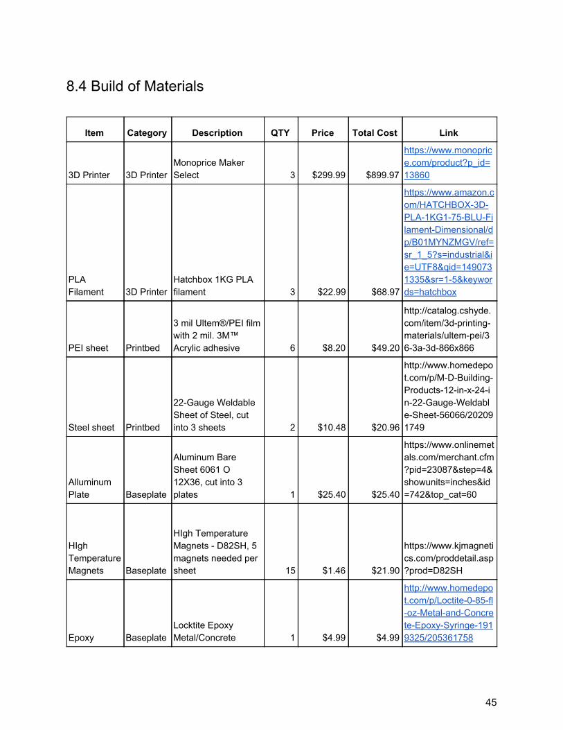
2.7 Cost Analysis
We can use our bill of materials as seen in section 8.4 as a reference for the total cost of the additional materials that we bought. Added to the current cost of a comparable new Fanuc arm, the entire system costs $32,350. In order for the cost of the system to be comparable to a non-automated printer farm, it would have to be incredibly reliable and require almost no human interaction or maintenance. The investment would break even when the cost for all materials in the system equals the wages and benefits that any employees would have earned. The investment becomes profitable when the cost of maintenance, replacement filament, and overhead is less than the cumulative profit from print requests. Often, printer farms have only one staff member assigned to the operation of their printers. The cost of the robot equals the cost of a human worker paid minimum wage after 2,818 hours.
2.8 Ethical Implications of Automation A main fear of automation is that it will take jobs away from humans [31]. Early
on, automation was primarily used for jobs that are dull, dangerous or dirty. However, the automation process did not stop there as robots became capable of completing more complex and skilled tasks. Workers found themselves competing with robots for jobs in the way that they feared. It was argued that robots would free workers for more interesting jobs or activities that require more skill [30]. However, workers replaced by robots do not have the ability to immediately transition in a new position without retraining, so the opportunity to have a better job often does not apply [30]. Therefore, automation is ethical as long as we provide instructions to laid off employees to allow them to return to the workforce alongside the robots or to change to a different profession.
10
3. Methodology
3.1 Printer The qualities considered in the examination of 3D printers for the use in this
project were: overall cost, location of the company’s headquarters, and if the software was open source. The expected budget constraint is $1000 and multiple printers are needed. Only American suppliers of 3D printers were considered for two reasons: faster, more reliable shipping and product support. Based on that knowledge, several companies were ranked higher and given more priority than others.
Table 1: 3D Printer Comparison
Printer Name Price Open
source Heated-
bed? Size
(inch) Notes
Printrbot Play $399 Y N 4X4X5 assembled and shipped in USA
Printrbot Simple $599 Y N 6X6X6 assembled and shipped in USA
Monoprice Maker Select $318 Y Y 8X8X7
assembled and shipped in USA (free shipping + 1 year warranty)
GeeeTech Prusa i3
$399 (Base $299, Shipping ~$100) Y Y 8X8X7
china + generic parts + assembling required
Mod-t $399 N N 4X6X5
da Vinci Jr. $329 N N 6X6X6
The team contacted several 3D printing companies to request academic
discounts on printers. The companies contacted for sponsorship included Monoprice, Printrbot, Ultimaker, Lulzbot and Dremel. Out of all the companies contacted only Printbot and Lulzbot replied, offering slight discounts and a possible partnership. Neither of the offers were taken as the 3D printers supplied by both companies cost over $1000 with the discount and the details of the partnership were too vague. The 3D printer
11
chosen for this project was the Monoprice Maker Select v2, displayed in Figure 2 below. When compared to its competitors, the printer has a remarkable amount of features for its low price of $330. Some features include: a heated bed, a LCD screen, an instructional manual, maintenance tools, a microSD card, and an open-source control board that supports 3rd party firmware [15][16]. This allows for two printers that have all of the desired qualities to fit the budget. An additional printer will be supplied out of pocket.
Figure 2: Monoprice Maker Select 3D Printer [16]
3.2 Robot
There were 3 options considered for the system’s plate manipulator: using a Fanuc LR Mate 200ib robotic arm, using a Thermo robotic arm or designing a custom robotic system.
The Fanuc is capable of lifting more than 2 kg, which is the minimum required payload for our project, but is the oldest of the three options. The Thermo is easier to integrate with than the Fanuc, but the Thermo can only lift a maximum of 2 kg. Ideally the load will not reach 2 kg, however, a robotic arm that allows for a bit of leeway is desirable. A custom robotic design would be the easiest to integrate and the maximum payload could be modified, but this is the most expensive option since each component would need to be purchased. In addition, a lot of time would be consumed designing, building and testing the robot. The Fanuc was chosen in the end.
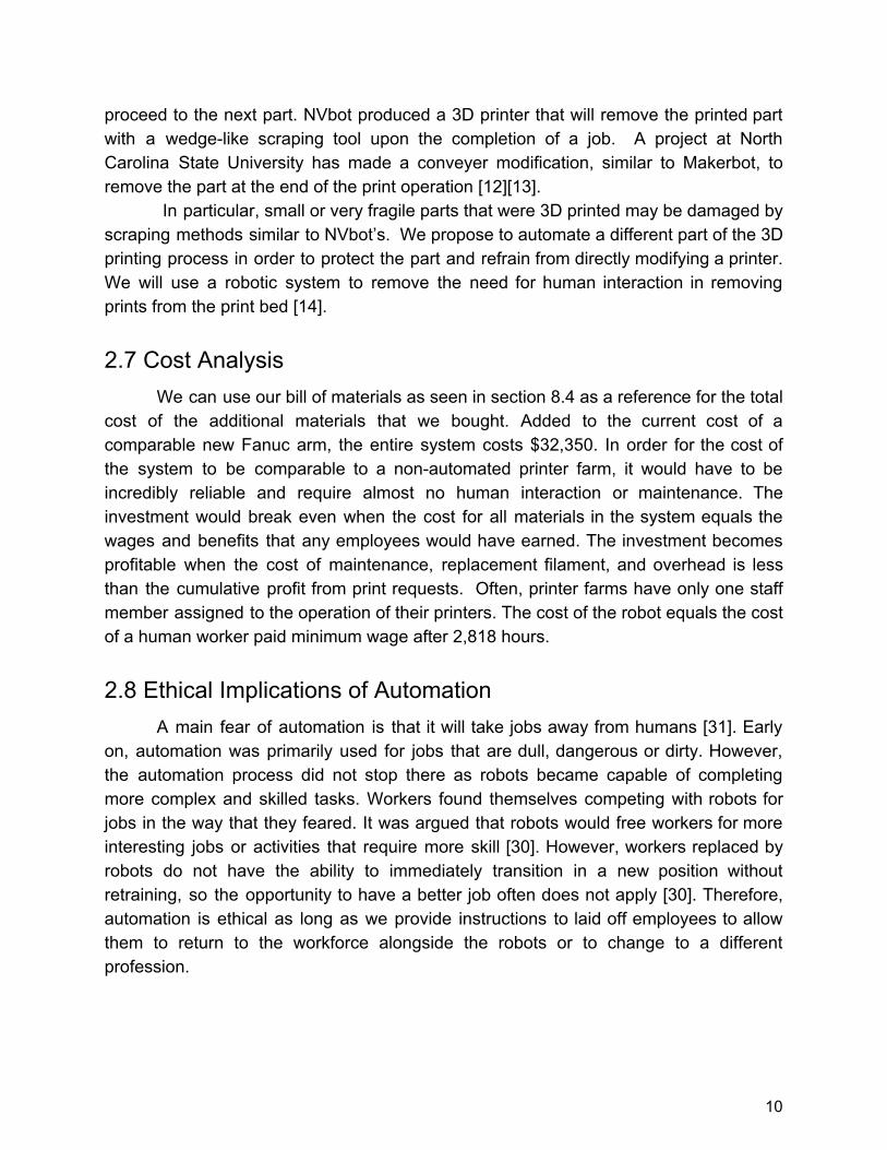
The Fanuc, displayed in Figure 3, possesses the following features: the robot has 6 degrees of freedom, which is more than enough to maneuver around the printers, and a 5kg payload. Also, WPI already owns a Fanuc LR Mate 200iB 5p, so no additional costs are incurred to acquire the robot.
12
Figure 3: Fanuc LR Mate 200iB 5p [27]
3.3 Printbed Due to the Fanuc’s payload being limited to 5kg, the project requires a print bed
that takes minimal vertical force to remove. The print bed also requires excellent PLA adhesion in order to prevent warping and to produce repeatable, successful prints. To satisfy these requirements, a magnetic base will be utilized in conjunction with a Polyetherimide (PEI) print surface. Instead of purchasing a print bed, the print bed will be designed and manufactured by the team.
The print bed will consist of two parts: a PEI layer and a steel sheet. PEI was chosen because it is recognized as a “miracle” print bed material by the RepRap community, which consists of experienced 3D printer users who have experimented with a wide array of print bed materials. With the combination of a heated bed and a PEI layer, the build plate is able to have excellent part adhesion for both PLA and ABS plastic. PEI is also durable and requires low maintenance. The PEI is adhered to a thin sheet of steel to allow the plate to stick to magnets as well as be durable enough to withstand the forces acted on by the robot [17]. Figure 4 displays the CAD model of the print bed and the actual print bed used in our project. The tab cutouts from the model were not added to the actual print beds due to the decision to use an active method of securing the plates rather than a passive method.
13
Figure 4: Printbed Comparison
3.4 Magnetic Base
A magnetic base made out of aluminum and high temperature magnets was chosen. The magnets within this base will attract the print bed, which as defined previously contains steel, thus preventing build plate sliding. Aluminum has very good thermal conductivity and is able to distribute heat evenly, which is crucial for a successful print job. If the PEI sheet has temperature differences across its surface, it loses effectiveness as a build surface.
The selected magnets have an individual pull force of 14.5N. Each base contains five magnets. If we visualize magnetic field as a vector pointing along the axis of the north and south poles, we can calculate the overall pull force using simple vector geometry. The Pythagorean theorem states , thus adding five vectors that √a2 + b2 = c2
are likely pointing in different directions equates to This means the base 2.4.√5 4.5· 1 2 = 3 has an average pull force of 32.4N. Ordinarily, magnets lose their magnetism at temperatures above 175F or 79.4C. In contrast, high temperature magnets can withstand 150C or 302F without diminishing its magnetic field [18][19]. Since the maximum temperature of a heated bed is 120 C or 248 F, these magnets will work well for the magnetic base. Figure 5, seen below, displays a CAD model of the magnetic base.
14
Figure 5: Magnetic Base CAD Model
3.5 End Effector
The team designed and built an end effector to manipulate the print beds. Three distinct designs were considered for part removal: a forklift, a conveyor belt and a gripper. In the end, the forklift was chosen due to the simplicity and low weight of the design. Two version were created over the course of the project, one passive and one active. A CAD model of the first version end effector is shown in Figure 6.
Figure 6: Forklift End Effector version 1
The first version of the end effector is completely passive and offered only two
shallow depressions for the print bed to rest in. The tabs on the print beds were meant to fit into the depressions on the forklift arms, preventing the print bed from sliding in the XY plane when in motion. The forklift end effector possesses several benefits over the conveyer and gripper options. First, there are no moving parts on this design and
15
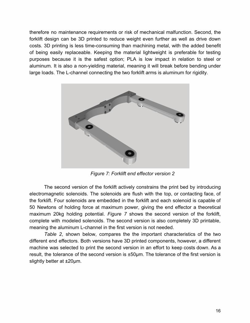
therefore no maintenance requirements or risk of mechanical malfunction. Second, the forklift design can be 3D printed to reduce weight even further as well as drive down costs. 3D printing is less time-consuming than machining metal, with the added benefit of being easily replaceable. Keeping the material lightweight is preferable for testing purposes because it is the safest option; PLA is low impact in relation to steel or aluminum. It is also a non-yielding material, meaning it will break before bending under large loads. The L-channel connecting the two forklift arms is aluminum for rigidity.
Figure 7: Forklift end effector version 2
The second version of the forklift actively constrains the print bed by introducing
electromagnetic solenoids. The solenoids are flush with the top, or contacting face, of the forklift. Four solenoids are embedded in the forklift and each solenoid is capable of 50 Newtons of holding force at maximum power, giving the end effector a theoretical maximum 20kg holding potential. Figure 7 shows the second version of the forklift, complete with modeled solenoids. The second version is also completely 3D printable, meaning the aluminum L-channel in the first version is not needed.
Table 2, shown below, compares the the important characteristics of the two different end effectors. Both versions have 3D printed components, however, a different machine was selected to print the second version in an effort to keep costs down. As a result, the tolerance of the second version is ±50µm. The tolerance of the first version is slightly better at ±20μm.
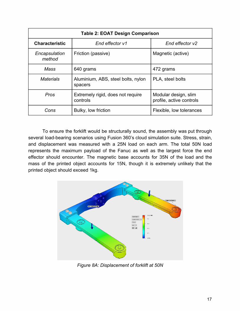
Cons Bulky, low friction Flexible, low tolerances To ensure the forklift would be structurally sound, the assembly was put through
several load-bearing scenarios using Fusion 360’s cloud simulation suite. Stress, strain, and displacement was measured with a 25N load on each arm. The total 50N load represents the maximum payload of the Fanuc as well as the largest force the end effector should encounter. The magnetic base accounts for 35N of the load and the mass of the printed object accounts for 15N, though it is extremely unlikely that the printed object should exceed 1kg.
Figure 8A: Displacement of forklift at 50N
17
The maximum simulated displacement of the forklift is 1.4mm, which occurs at the farthest end point. The results of the simulation indicate that the right arm will yield 0.5mm more than the left arm. This result does not have a logical explanation, therefore we will proceed with the assumption that both arms will displace 1.4mm.
Figure 8B: Strain of forklift at 50N
The maximum strain present in the end effector is in the thinnest section of the
base, which supports the forklift arms. The strain of 0.001303mm/mm is calculated using an equivalent, or Von Mises, magnitude representing all six tensors in the XX, XY, XZ, YY, YZ, and ZZ planes. Using this method, we are able to approximate the sum of strain in any given 1mm cubic slice in the model. The strain value indicates a 1mm cubic slice will deform at most 1um, which is well within our tolerance.
18
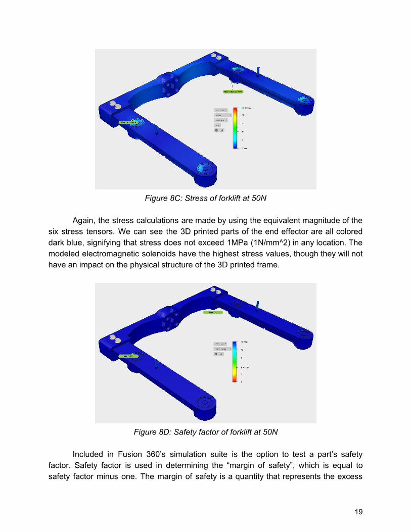
Figure 8C: Stress of forklift at 50N
Again, the stress calculations are made by using the equivalent magnitude of the
six stress tensors. We can see the 3D printed parts of the end effector are all colored dark blue, signifying that stress does not exceed 1MPa (1N/mm^2) in any location. The modeled electromagnetic solenoids have the highest stress values, though they will not have an impact on the physical structure of the 3D printed frame.
Figure 8D: Safety factor of forklift at 50N
Included in Fusion 360’s simulation suite is the option to test a part’s safety
factor. Safety factor is used in determining the “margin of safety”, which is equal to safety factor minus one. The margin of safety is a quantity that represents the excess
19
capacity of a part. The margin of safety indicates how many more loads of the current test it can withstand before failing. In this case, the margin of safety is 14 for over 98% of the end effector. The margin of safety indicates a force greater than or equal to 700N on each arm will cause a failure. According to simulations, the forklift design appears to be the most versatile and safe option.
3.6 Plate Storage The workspace contains a monitored shelving system to store clean print beds
and a passive roller to store beds with completed prints. Each layer of the shelf consists of two, centered aluminium L-brackets. The brackets keep the print bed level and provide room for the end of arm tooling to lift and remove plates. Each shelf has a limit switch to detect if the shelf is occupied. This data is used to command the Fanuc to the appropriate shelf. The passive roller is a gravity-assisted storage bay in which used print beds roll down a gentle slope into a wooden cubby.
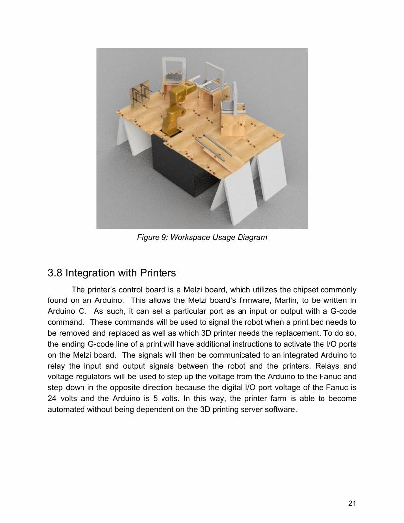
3.7 Workspace Usage The workspace given has been optimized to fit all necessary structures. The
proposed environment can be seen in the diagram below. The 3 printers and prepared plate storage rack encircle the Fanuc’s workspace, while the conveyor belt system moves removed print beds to a place where they can cool and await part removal. The prepared plate storage rack will have 6 shelves that are 240mm by 240mm. Each shelf will have a raised platform that is 200mm by 200mm so that the forklift can maneuver underneath the print beds to lift them. This diagram was made with the assumption that the space given is 4ft by 8ft. If necessary, the conveyor belt can be adapted to accommodate changes in the amount of space available. Since we are only using 6 plates, a full-sized conveyer belt is unnecessary, but can be extended to increase productivity and allow for larger print volumes in the future.
20
Figure 9: Workspace Usage Diagram
3.8 Integration with Printers
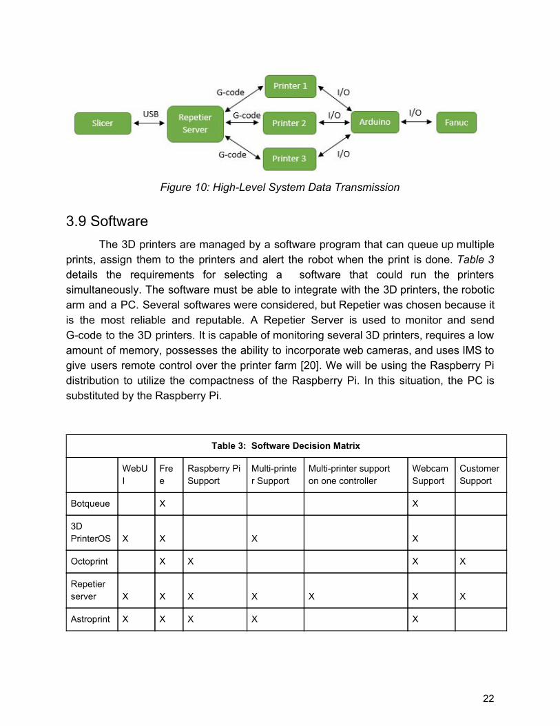
The printer’s control board is a Melzi board, which utilizes the chipset commonly found on an Arduino. This allows the Melzi board’s firmware, Marlin, to be written in Arduino C. As such, it can set a particular port as an input or output with a G-code command. These commands will be used to signal the robot when a print bed needs to be removed and replaced as well as which 3D printer needs the replacement. To do so, the ending G-code line of a print will have additional instructions to activate the I/O ports on the Melzi board. The signals will then be communicated to an integrated Arduino to relay the input and output signals between the robot and the printers. Relays and voltage regulators will be used to step up the voltage from the Arduino to the Fanuc and step down in the opposite direction because the digital I/O port voltage of the Fanuc is 24 volts and the Arduino is 5 volts. In this way, the printer farm is able to become automated without being dependent on the 3D printing server software.
21
Figure 10: High-Level System Data Transmission
3.9 Software The 3D printers are managed by a software program that can queue up multiple
prints, assign them to the printers and alert the robot when the print is done. Table 3 details the requirements for selecting a software that could run the printers simultaneously. The software must be able to integrate with the 3D printers, the robotic arm and a PC. Several softwares were considered, but Repetier was chosen because it is the most reliable and reputable. A Repetier Server is used to monitor and send G-code to the 3D printers. It is capable of monitoring several 3D printers, requires a low amount of memory, possesses the ability to incorporate web cameras, and uses IMS to give users remote control over the printer farm [20]. We will be using the Raspberry Pi distribution to utilize the compactness of the Raspberry Pi. In this situation, the PC is substituted by the Raspberry Pi.
Table 3: Software Decision Matrix
WebUI
Free
Raspberry Pi Support
Multi-printer Support
Multi-printer support on one controller
Webcam Support
Customer Support
Botqueue X X
3D PrinterOS X X X X
Octoprint X X X X
Repetier server X X X X X X X
Astroprint X X X X X
22
4. Results This section details every revision and the outcome of the project in relation to
the goals the team set out to accomplish. In short, the team
4.1 Design Changes
4.1.1 Magnetic Base One of the first things the team discovered was the magnets used for the
magnetic base were stronger than expected. The design of the Base was changed to hold fewer magnets. Instead of 12 per base plate each base now contains 5 (One on each corner plus one on the middle). Instead of press-fitting the magnets into the base plate, epoxy was used to glue the magnets to the base plate. Previously, the magnets would occasionally stay attached to the print bed and slide out of the base plate. The material used for the magnetic base remained the same. Figure 11 shows the final magnetic base that was mounted to the printers.
Figure 11: Magnetic Base
The purpose of this change is to save resources and correct for an assumed
variable that led to a miscalculation. Section 3.4 discusses the force exerted by the magnets in the base. If we apply the same equation used in that section and account for seven additional magnets, we can calculate the force required for the Fanuc to remove a print bed: . It is obvious that a force of 50N is far too high and 0.23N√14.5 22 · 1 = 5 could exceed the Fanuc’s maximum payload.
23
4.1.2 End Effector The major problem with the first version is the inability to constrain the print bed
in the Z axis. The problem was discovered through two observations. First, when using the Fanuc to remove a print bed attached to a printer, the bed has a tendency to “leap” upwards and land on the forklift in a compromising position. The “leap” is caused by the reactive upwards force of the forklift as it moves the steel print bed vertically out of range of the magnets. Within the magnetic field, the print bed pushes downward on the forklift, generating a reactive force on the forklift pointing upwards. Upon leaving the magnetic field, the downward force generated by the print bed ceases to exist and the print bed accelerates upward due to the unbalanced forces in the Z axis. Second, the print bed was observed vibrating during extended linear motions. The vibration, though not confirmed, is most likely caused by the Fanuc drive servos.
Figure 12: End Effector
4.1.3 Plate Storage A rack was used to hold the replacement print beds. There were 3 shelves (one
for each 3D printer) each with one print bed. Limit switches were placed on each shelf that were connected to the Arduino. These limit switches signalled the Arduino whether the shelves were empty or filled. The final code did not rely on these limit switches. The Difficulties subsection of Discussions gives an explanation as to why this was done. A
24
passive conveyer belt was used to store finished prints. However, the final design changed from the original design. Figures 13 and 14 show the final design of the storage rack and conveyor respectively.
Figure 13: Replacement rack
Figure 14: Storage conveyer
4.1.4 Raspberry Pi Usage Early on in the project, it was found that IO lines from the onboard controller of
the printers was very limited. In order to fix this, we utilized a special feature with the
25
Raspberry Pi distribution of Repetier-Server. In the software, we are able to run custom python scripts that can manipulate the server and the device it is running on. This allowed us to utilize the Raspberry Pi’s GPIO lines to us as serial line to the Arduino. Using a voltage divider for the Raspberry Pi’s input lines, we were able to effectively communicate between the Raspberry Pi and the Arduino.
Figure 15: Revised High-Level System Data Transmission
4.1.5 Workspace Usage In the original design the Fanuc should have been in the center of the
workspace. However, the Fanuc was already mounted unto a small workspace. Instead of unmounting and remounting the Fanuc, the team opted on placing the new workspace over the old one. This placed the Fanuc in the middle of the southern edge of the workspace. The rest of the workspace had to be placed in an ark. Figure 16 shows how the workspace was arranged.
26
Figure 16: Workspace
The replacement rack was placed left of the Fanuc. In front of the Fanuc were
the three 3D printers in an arc formation. To the right of the Fanuc was the print bed storage conveyer.
4.2 Achievements In a general sense, the project was successfully completed. The workspace was
properly constructed in such a way that the Fanuc could reach and interact with all objects within the workspace. All components were properly programmed and were capable of communicating with each other. The workflow was as follows: The 3D printers received a print job from the Repetier Server on the Raspberry Pi. Once the 3D printers finished their print jobs, the Arduino would signal the Fanuc. The Fanuc would then remove and replace the printbed for each of the 3D printers. When finished, the Fanuc would send a signal to the Arduino. The Arduino would then signal the Repetier Server within the Raspberry Pi that the printbed has been replaced. The Repetier Server would then free up the 3D printer to accept a new print job and the cycle would repeat.
While the goals in general were met, due to several difficulties the whole process was not automated. The team had to replace the Arduino and the Raspberry Pi. The Arduino’s microprocessor got damaged and the Raspberry Pi was no longer capable of receiving signal. Due to time and resources constraints as well as some other difficulties, the Raspberry Pi was not replaced. Thus the team was forced to manually
27
communicate with the Arduino once a print was done. However, this was the only issue that the team was unable to fully address the rest of the project goals were completely met. Also none of the stretch goals were met. For a full explanation of the difficulties encountered please refer to the Difficulties subsection within the Discussion section. For details on the goals and stretch goals please refer to this project's proposal.
5. Discussion
5.1 Difficulties The team faced multiple setbacks throughout the project, predominantly
unexpected hardware failures. The Fanuc controller had a blown fuse that resulted in it being unable to send or receive data through its digital I/O pins or supply power through any of its Vcc pins. This halted the entire project due to it delaying our testing period. Once the fuse was replaced, the Fanuc could send data and supply power again.
A pair of major setbacks caused the team’s demo to be pushed to another date. The setback was caused because the fuse was blown again because of an accidental ground loop between the Fanuc’s Robot and Data ports. However, this caused an unexpected disruption in the I/O pins resulting in their associated pin numbers changing. In addition, the Raspberry Pi overheated unrelated to the Fanuc’s issue. The Raspberry Pi, while still able to run the Repetier Server was unable to transmit a signal when a print was done. Another Raspberry Pi was purchased to replace the old one. However, the new Raspberry Pi overheated due to receiving data while unpowered and can no longer be used. In the end, the old Raspberry Pi was used since it could still host the server. The team had to manually send data to the Arduino when the prints were done. This was all done due to time constraints and the lack of nearby stores that sold a Raspberry Pi.
The Arduino Mega had to be replaced as well, due to an issue isolating the Fanuc’s 24V data lines from the Mega’s input ports. An Arduino Uno was used to replace the Mega and a relay with a voltage regulator replaced the faulty circuit. While smaller and with less processing power, the Uno was enough to run the program. Only a small change had to be done due to the limited number of pins on the Uno. The change was that the replacement shelves, which were managed independently, are now tied to the 3D printers in code, i.e. when printer 1 needs a replacement the robot automatically goes to shelf 1.
28
6. Future Work This section is intended for whomever will pick up this project. It will contain
suggestions on some areas that could be improved and how to improve them. This project is created primarily for use in higher education settings where the
people who are responsible for the printer farm have other, more pressing, responsibilities. It would be intended to serve an entire student population and the project proposed in this document would have to be expanded upon to do so. Depending on the space available, a gantry could be added so that the robot can serve more printers. This would allow for both horizontal and vertical robot movement.
The team highly recommends using a modern robot. Some of the biggest difficulties were caused by the Fanuc, which has become obsolete and has limited support. The model was no longer archived by the manufacturer, which made it impossible to code using any offline software. Also the robot had no ethernet port so any program that had to be uploaded to the robot had to be done through manual transfer. The lack of proper documentation made it difficult to find any I/O lines. These were some of the issues that made the project more difficult and can be easily solved with the use of a more modern and documented robot.
Another possible goal for future projects is to mount a camera on each 3D printer to remotely verify the project, reducing the need for the presence of the operator in the room during the printing process. If verified, the robot would remove the part from the printer and place it onto a cooling rack. If the print is successful, the printer starts the next job in the queue. If unsuccessful, the printer is taken offline and goes into maintenance to attempt to determine the cause of the print failure [11].
7. Bibliography
[1] H. Lipson and M. Kurman, Fabricated: The new world of 3D printing. John Wiley, 2013. [Online]. Available: https://books.google.com/books?hl=en&lr=&id=MpLXWHp-srIC&oi=fnd&pg=PA1&dq=history+of+3D+printing&ots=Z2fTuOK03C&sig=86t3Mq8ZJ5KmBxNWn0WH5wb7_uA#v=onepage&q&f=false. Accessed: Sep. 19, 2016.
[2] S. J. Grunewald, "San Diego 3D printing company cultivates the printer farm," 3D Printing Industry, 2014. [Online]. Available: http://3dprintingindustry.com/news/san-diego-3d-printing-company-cultivates-printer-farm-28195/. Accessed: Sep. 19, 2016. [3] D. 3 I. TV, "3DPI.TV - 3D printing inventor to receive honour from national inventors hall of fame," 3D Printing Industry, 2014. [Online]. Available: http://3dprintingindustry.com/news/3dpi-tv-3d-printing-inventor-25021/. Accessed: Sep. 19, 2016. [4] 3 P. D. Industry, "The free beginner’s guide - history," 3D Printing Industry, 2016. [Online]. Available: http://3dprintingindustry.com/3d-printing-basics-free-beginners-guide/history/. Accessed: Sep. 19, 2016. [5] T. Wohlers and T. Gornet, "History of additive manufacturing," in badraccoon. [Online]. Available: http://badraccoon.gr/wp/wp-content/uploads/2015/01/history2011.pdf. Accessed: Sep. 19, 2016. [6] D. Feeney, "Not all heated beds are created equal - SD3D printing," in 3D Printing, SD3D Printing, 2015. [Online]. Available: http://www.sd3d.com/not-all-heated-beds-are-created-equal/. Accessed: Sep. 19, 2016. [7] J. L. Bouthillier, "Heat beds in 3D printing – advantages and equipment," 2016. [Online]. Available: https://bootsindustries.com/heat-bed-3d-printing/. Accessed: Sep. 19, 2016. [8] T. Rogers, "Everything you need to know about Polylactic acid (PLA)," 2015. [Online]. Available: https://www.creativemechanisms.com/blog/learn-about-polylactic-acid-pla-prototypes. Accessed: Sep. 20, 2016. [9] T. Rogers, "Everything you need to know about ABS plastic," in Creative Mechanisms, 2015. [Online]. Available: https://www.creativemechanisms.com/blog/everything-you-need-to-know-about-abs-plastic. Accessed: Sep. 20, 2016.
[10] S. J. Grunewald, "Former MakerBot team launches voodoo manufacturing 3D printing service bureau," in 3D Printers, 3DPrint.com, 2015. [Online]. Available: https://3dprint.com/99194/voodoo-3d-printing-bureau/. Accessed: Oct. 14, 2016. [11] Alec, "Is 3D printing a viable and affordable alternative to injection molding production?," in 3D printer and 3D printing news, 3ders.org, 2014. [Online]. Available: http://www.3ders.org/articles/20141106-is-3d-printing-technology-a-viable-and-affordable-alternative-to-injection-molding-production.html. Accessed: Oct. 15, 2016. [12] NC State ECE, "3d printer - automatic print removal," in YouTube, YouTube, 2014. [Online]. Available: https://www.youtube.com/watch?v=bf4Rsh_3sMU. Accessed: Oct. 15, 2016. [13] C. Pax, Z. Smith, A. Mayer, N. Pettis, and M. Industries, Patent US8282380 - automated 3D build processes. Google Books, 2010. [Online]. Available: https://www.google.com/patents/US8282380?dq=inassignee:%22Makerbot+Industries%22&ei=Ht5nUoTKF87wkQe5mYCYBg. Accessed: Oct. 15, 2016. [14] N. V. R. Corporation, "Products," in NVBots, 2016. [Online]. Available: https://nvbots.com/products/ Accessed: Oct. 15, 2016. [15] Amazon, "Monoprice 13860 maker select 3d printer V2," in Amazon.com: Industrial & Scientific, Amazon, 1996. [Online]. Available: https://www.amazon.com/Monoprice-Select-Printer-Heated-Filament/dp/B018GZBC3Y/ref=sr_1_sc_1?s=industrial&ie=UTF8&qid=1473620084&sr=1-1-spell&keywords=monoprice+maker+selct. Accessed: Oct. 15, 2016. [16] Monoprice, "Maker select 3D printer v2," in Monoprice, Monoprice.com, 2016. [Online]. Available: http://www.monoprice.com/product?p_id=13860. Accessed: Oct. 15, 2016. [17] M. Doll, "Part Removal of 3D Printed Parts," in DSpace.mit.edu, 2014. [Online]. Available: https://dspace.mit.edu/bitstream/handle/1721.1/92203/897366098-MIT.pdf?sequence=2. Accessed: Oct. 15, 2016. [18] NA, "K&J magnetics: D81SH," in K&J Magnetics, Inc. [Online]. Available: https://www.kjmagnetics.com/proddetail.asp?prod=D81SH&cat=167. Accessed: Oct. 15, 2016.
[19] NA, "K&J magnetics: D82SH," in K&J Magnetics. [Online]. Available: https://www.kjmagnetics.com/proddetail.asp?prod=D82SH. Accessed: Oct. 15, 2016. [20] NA, "Control your 3d printer from everywhere - anytime!," in Repitier Server, Repetier-Server. [Online]. Available: https://www.repetier-server.com. Accessed: Oct. 15, 2016. [21] NA, "Introduction," in Marlin, Marlin 3D Printer Firmware. [Online]. Available: http://www.marlinfw.org/docs/basics/introduction.html Accessed: Oct. 15, 2016. [22] David Bak, "Rapid prototyping or rapid production? 3D printing processes move industry towards the latter",Assembly Automation, Vol. 23 Iss: 4, pp.340 - 345 [23] R. W. Bybee, The case for STEM education: Challenges and opportunities. Arlington: National Science Teachers Association, 2014. [24] "Dimension 1200es 3D modeling printers," in Stratasys, 2015. [Online]. Available: http://www.stratasys.com/3d-printers/design-series/dimension-1200es. Accessed: Sep. 19, 2016. [25] E. Buehler, N. Comrie, M. Hofmann, S. McDonald, and A. Hurst, "Investigating the implications of 3D printing in special education," ACM Transactions on Accessible Computing, vol. 8, no. 3, pp. 1–28, Mar. 2016. [26] T. Rowe Price Connections, “A Brief History of 3D Printing”. [Online]. Available: https://individual.troweprice.com/staticFiles/Retail/Shared/PDFs/3D_Printing_Infographic_FINAL.pdf. Accessed: Sep. 19, 2016. [27] NA, "FANUC LRMate 200iB/5P RJ3iB," in Robot Work. [Online]. Available: https://www.robots.com/fanuc/lr-mate-200ib-5p. Accessed: Oct. 19, 2016 [28] NA, "Understanding IMS," 2013. [Online]. Available: http://dataedge.ie/wp-content/uploads/2013/07/Network-Testing-Understanding-IMS.pdf. Accessed: Nov. 28, 2016. [29] NA, “United States Average Hourly Wages in Manufacturing”. [Online]. Available: http://www.tradingeconomics.com/united-states/wages-in-manufacturing. Accessed: Jan. 23, 2016.
[30] Lin, Patrick,Abney,Keith,Bekey, Gearge A. “Robot Ethics”. MIT Press, December 2011, Accessed: Jan 23, 2016. [31] Ramaswamy, Joshi. “Automation and Ethics”. Springer Handbook of Automation. Springer Berlin Heidelberg. 2009. Accessed: Jan. 23, 2016
8. Appendix
8.1 Arduino Code
8.1.1 Integration Code /* @Title: Integration Circuit @Purpose: To act as an intermediary between the 3d pritners and the Fanuc Robot Arm @authors: Lauren Pontbriant, Alex Ruggiero, Kevin A. Valente-Comas */ //Pin Registers //Printer I/O ports
33
const int p1i = 8; const int p1o = 9; const int p2i = 10; const int p2o = 11; const int p3i = 12; const int p3o = 13; //Relay output lines to Fanuc const int relay1 = 7; //printer 1 & Top Shelf const int relay2 = 6; //printer 2 & Mid Shelf const int relay3 = 5; //printer 3 & Bot SHelf const int relay4 = 4; //Fanuc Signal //Voltage Regulator input lines from Fanuc const int fanucIn = 3; //cycle completion //Shelf limit switches const int s1 = 19; const int s2 = 20; const int s3 = 21; void setup() { // initialize serial communication at 9600 bits per second: Serial.begin(9600); //set pinmode pinMode(p1i, INPUT); pinMode(p1o, OUTPUT); pinMode(p2i, INPUT); pinMode(p2o, OUTPUT); pinMode(p3i, INPUT); pinMode(p3o, OUTPUT); pinMode(relay1, OUTPUT); pinMode(relay2, OUTPUT); pinMode(relay3, OUTPUT); pinMode(fanucIn, INPUT); pinMode(s1, INPUT); pinMode(s2, INPUT); pinMode(s3, INPUT); }
SignalFanuc(); //wait for signal from Fanuc for completion while (digitalRead(fanucIn) == LOW) {
delay(10); } Serial.println("Signal Recieved"); //set output line back to 0 if (pr == 1)
digitalWrite(relay1, LOW); if (pr == 2)
digitalWrite(relay2, LOW); if (pr == 3)
digitalWrite(relay3, LOW); } //Function for dropOff void Replace(int sr) { //Check which shelf has a replacement print bed int shelfN = ShelfN(); //Tell Fanuc which Shelf to pickup if (shelfN == 1)
if (shelfN == 2) digitalWrite(relay2, HIGH); Serial.println("Picking print bed2");
if (shelfN == 3) digitalWrite(relay3, HIGH); Serial.println("Picking print bed3");
SignalFanuc(); //wait for signal from Fanuc for completion while (digitalRead(fanucIn) == LOW) {
delay(10); } Serial.println("Signal Recieved"); //set output line back to 0 if (shelfN == 1)
36
digitalWrite(relay1, LOW); if (shelfN == 2)
digitalWrite(relay2, LOW); if (shelfN == 3)
digitalWrite(relay3, LOW); //Tell Fanuc Printer pr is drop off over Relay number pr if (sr == 1)
digitalWrite(relay1, HIGH); if (sr == 2)
digitalWrite(relay2, HIGH); if (sr == 3)
digitalWrite(relay3, HIGH); SignalFanuc(); //wait for signal from Fanuc for completion while (digitalRead(fanucIn) == LOW) {
delay(10); } //set output line back to 0 if (sr == 1)
digitalWrite(relay1, LOW); if (sr == 2)
digitalWrite(relay2, LOW); if (sr == 3)
digitalWrite(relay3, LOW); } //Function for Shelf int ShelfN() { int n = 0; while (n = 0) {
if (digitalRead(s1) == HIGH) { //shelf1 is not empty n = 1;
} else if (digitalRead(s2) == HIGH) { //shelf2 is not empty
n = 2 } else if (digitalRead(s3) == HIGH) { //shelf3 is not empty
n = 3; }
} return n; }
37
//Send Pulse Signal to Fanuc void SignalFanuc() { digitalWrite(relay4) == HIGH; for (int i, i < 15, i++) {
Serial.print ("Signaling Fanuc"); } digitalWrite(relay4) == LOW; } //Send Signal back to Raspberry PI CycleComplete(int pi) { //Tell Fanuc Printer pr is pickup over Relay number pr if (pi == 1) {
digitalWrite(p1o, HIGH); while (digitalRead(p1i) == HIGH) {
delay(10); } digitalWrite(p1o, LOW);
} else if (pi == 2) {
digitalWrite(p2o, HIGH); while (digitalRead(p2i) == HIGH) {
delay(10); } digitalWrite(p2o, LOW);
} else if (pi == 3) {
digitalWrite(p3o, HIGH); while (digitalRead(p3i) == HIGH) {
delay(10); } digitalWrite(p3o, LOW);
} }
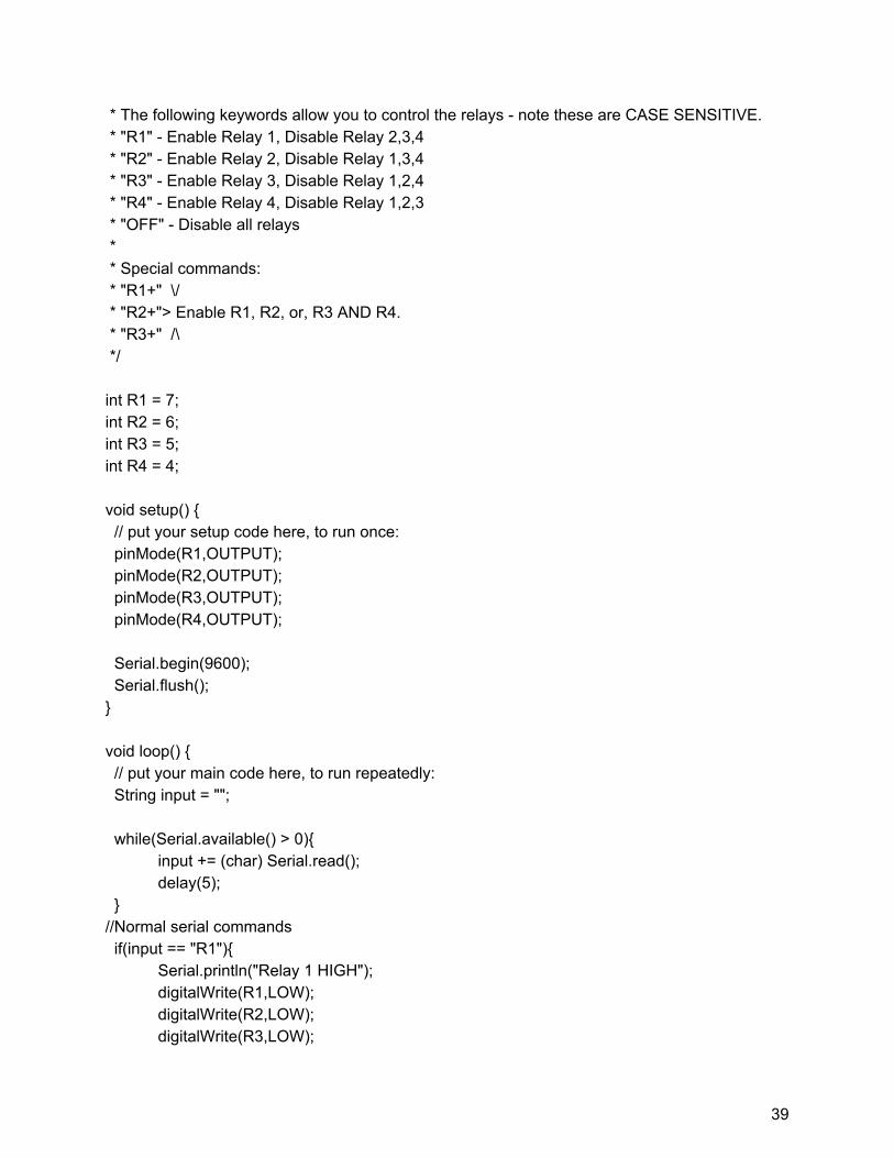
8.1.2 Arduino and Fanuc Integration Code /*HOW TO RUN THIS CODE * First, make sure you've selected the appropriate port and board model. * Second, upload the script and open the Serial monitor (Tools > Serial Monitor) *
38
* The following keywords allow you to control the relays - note these are CASE SENSITIVE. * "R1" - Enable Relay 1, Disable Relay 2,3,4 * "R2" - Enable Relay 2, Disable Relay 1,3,4 * "R3" - Enable Relay 3, Disable Relay 1,2,4 * "R4" - Enable Relay 4, Disable Relay 1,2,3 * "OFF" - Disable all relays * * Special commands: * "R1+" \/ * "R2+"> Enable R1, R2, or, R3 AND R4. * "R3+" /\ */ int R1 = 7; int R2 = 6; int R3 = 5; int R4 = 4; void setup() { // put your setup code here, to run once: pinMode(R1,OUTPUT); pinMode(R2,OUTPUT); pinMode(R3,OUTPUT); pinMode(R4,OUTPUT); Serial.begin(9600); Serial.flush(); } void loop() { // put your main code here, to run repeatedly: String input = ""; while(Serial.available() > 0){
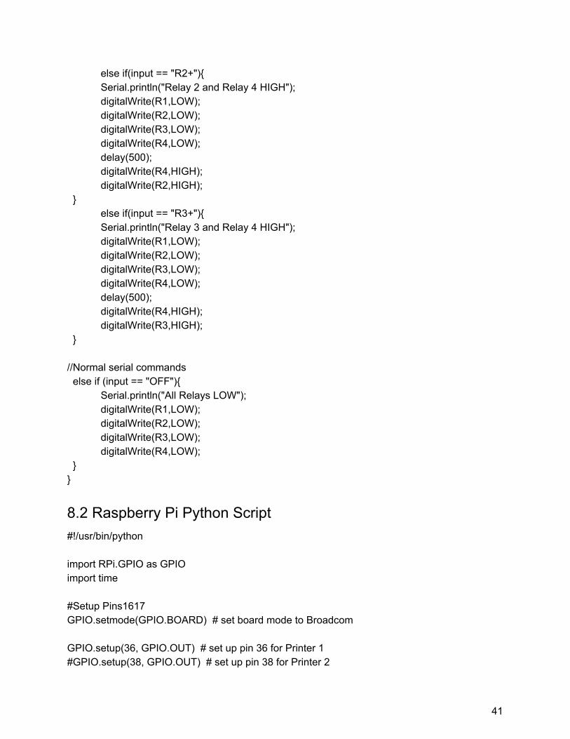
8.2 Raspberry Pi Python Script #!/usr/bin/python import RPi.GPIO as GPIO import time #Setup Pins1617 GPIO.setmode(GPIO.BOARD) # set board mode to Broadcom GPIO.setup(36, GPIO.OUT) # set up pin 36 for Printer 1 #GPIO.setup(38, GPIO.OUT) # set up pin 38 for Printer 2
41
#GPIO.setup(40, GPIO.OUT) # set up pin 40 for Printer 3 GPIO.setup(33, GPIO.IN, pull_up_down=GPIO.PUD_DOWN) # set up pin 33 for Printer 1 #GPIO.setup(35, GPIO.IN, pull_up_down=GPIO.PUD_DOWN) # set up pin 35 for Printer 2 #GPIO.setup(37, GPIO.IN, pull_up_down=GPIO.PUD_DOWN) # set up pin 37 for Printer 3 print "Begin Printer 1 Integration" GPIO.output(36, 1) # turn on pin 36 print "Waiting for Signal" time.sleep(1) GPIO.wait_for_edge(33, GPIO.RISING) # wait for input from pin 33 GPIO.output(36, 0) # turn off pin 36 print "Signal Recieved" GPIO.cleanup()
8.3 Fanuc Code J P[1:HOME] 50% CNT50
WAIT RI[4]=ON WAIT RI[4]=OFF R[1]=0 WAIT 2.00(sec) IF RI[1]=ON, JMP LBL[1] IF RI[2]=ON, JMP LBL[2] IF RI[3]=ON, JMP LBL[3] LBL[1] R[1]=1
J P[23] 25% CNT50 L P[24] 500mm/sec FINE
DO[107]=ON J P[25] 25% FINE L P[26] 1000mm/sec CNT10 J P[27] 100% CNT100
JMP LBL[4] LBL[2] R[1]=2
J P[18] 25% CNT50 L P[19] 500mm/sec FINE
DO[107]=ON J P[20] 25% FINE L P[21] 1000mm/sec CNT10 J P[22] 100% CNT100
42
JMP LBL[4] LBL[3] R[1]=3
J P[13] 25% CNT50 L P[14] 500mm/sec FINE
DO[107]=ON J P[15] 25% FINE L P[16] 1000mm/sec CNT10 J P[17] 100% CNT100