Albert J. Juhasz Glenn Research Center, Cleveland, Ohio A Mass Computation Model for Lightweight Brayton Cycle Regenerator Heat Exchangers NASA/TM—2010-216799 September 2010 AIAA–2010–7087 https://ntrs.nasa.gov/search.jsp?R=20100037206 2018-08-26T19:48:15+00:00Z
Transcript
Albert J. JuhaszGlenn Research Center, Cleveland, Ohio
A Mass Computation Model for Lightweight Brayton Cycle Regenerator Heat Exchangers
Since its founding, NASA has been dedicated to the advancement of aeronautics and space science. The NASA Scientifi c and Technical Information (STI) program plays a key part in helping NASA maintain this important role.
The NASA STI Program operates under the auspices of the Agency Chief Information Offi cer. It collects, organizes, provides for archiving, and disseminates NASA’s STI. The NASA STI program provides access to the NASA Aeronautics and Space Database and its public interface, the NASA Technical Reports Server, thus providing one of the largest collections of aeronautical and space science STI in the world. Results are published in both non-NASA channels and by NASA in the NASA STI Report Series, which includes the following report types: • TECHNICAL PUBLICATION. Reports of
completed research or a major signifi cant phase of research that present the results of NASA programs and include extensive data or theoretical analysis. Includes compilations of signifi cant scientifi c and technical data and information deemed to be of continuing reference value. NASA counterpart of peer-reviewed formal professional papers but has less stringent limitations on manuscript length and extent of graphic presentations.
• TECHNICAL MEMORANDUM. Scientifi c
and technical fi ndings that are preliminary or of specialized interest, e.g., quick release reports, working papers, and bibliographies that contain minimal annotation. Does not contain extensive analysis.
• CONTRACTOR REPORT. Scientifi c and
technical fi ndings by NASA-sponsored contractors and grantees.
• CONFERENCE PUBLICATION. Collected papers from scientifi c and technical conferences, symposia, seminars, or other meetings sponsored or cosponsored by NASA.
• SPECIAL PUBLICATION. Scientifi c,
technical, or historical information from NASA programs, projects, and missions, often concerned with subjects having substantial public interest.
• TECHNICAL TRANSLATION. English-
language translations of foreign scientifi c and technical material pertinent to NASA’s mission.
Specialized services also include creating custom thesauri, building customized databases, organizing and publishing research results.
For more information about the NASA STI program, see the following:
• Access the NASA STI program home page at http://www.sti.nasa.gov
• E-mail your question via the Internet to help@
sti.nasa.gov • Fax your question to the NASA STI Help Desk
at 443–757–5803 • Telephone the NASA STI Help Desk at 443–757–5802 • Write to:
NASA Center for AeroSpace Information (CASI) 7115 Standard Drive Hanover, MD 21076–1320
Albert J. JuhaszGlenn Research Center, Cleveland, Ohio
A Mass Computation Model for Lightweight Brayton Cycle Regenerator Heat Exchangers
NASA/TM—2010-216799
September 2010
AIAA–2010–7087
National Aeronautics andSpace Administration
Glenn Research CenterCleveland, Ohio 44135
Prepared for the8th International Energy Conversion Engineering Conference (IECEC)sponsored by the American Institute of Aeronautics and AstronauticsNashville, Tennessee, July 25–28, 2010
Acknowledgments
This work was supported by the Power and On-Board Propulsion Division, Thermal Energy Conversion Systems Branch at NASA Glenn Research Center.
Available from
NASA Center for Aerospace Information7115 Standard DriveHanover, MD 21076–1320
National Technical Information Service5301 Shawnee Road
Alexandria, VA 22312
Available electronically at http://gltrs.grc.nasa.gov
Level of Review: This material has been technically reviewed by technical management.
This report is a formal draft or working paper, intended to solicit comments and
ideas from a technical peer group.
NASA/TM—2010-216799 1
A Mass Computation Model for Lightweight Brayton Cycle Regenerator Heat Exchangers
Albert J. Juhasz
National Aeronautics and Space Administration Glenn Research Center Cleveland, Ohio 44135
Abstract Based on a theoretical analysis of convective heat transfer across large internal surface areas, this
paper discusses the design implications for generating lightweight gas-gas heat exchanger designs by packaging such areas into compact three-dimensional shapes. Allowances are made for hot and cold inlet and outlet headers for assembly of completed regenerator (or recuperator) heat exchanger units into closed cycle gas turbine flow ducting.
Surface area and resulting volume and mass requirements are computed for a range of heat exchanger effectiveness values and internal heat transfer coefficients. Benefit cost curves show the effect of increasing heat exchanger effectiveness on Brayton cycle thermodynamic efficiency on the plus side, while also illustrating the cost in heat exchanger required surface area, volume, and mass requirements as effectiveness is increased. The equations derived for counterflow and crossflow configurations show that as effectiveness values approach unity, or 100 percent, the required surface area, and hence heat exchanger volume and mass tend toward infinity, since the implication is that heat is transferred at a zero temperature difference. To verify the dimensional accuracy of the regenerator mass computational procedure, calculation of a regenerator specific mass, that is, heat exchanger weight per unit working fluid mass flow, is performed in both English and SI units. Identical numerical values for the specific mass parameter, whether expressed in lb/(lb/sec) or kg/(kg/sec), show the dimensional consistency of overall results.
Nomenclature a passage height dimension (<0.01 m for plate-fin HX) AW ≈ (AW + AC)/2 average surface area Ch = (Wcp)h hot fluid capacity rate (W/K) CC = (Wcp)C cold fluid capacity rate (W/K), also Cmin., and Cmax, are, respectively, the smaller and
larger of the CC and Ch values CPC ,CPT specific heats for the compressor and turbine flows dCAS density of casing material (kg/m3) eC surface effectiveness for cold area, AC eh surface effectiveness for hot area, Ah εRG regenerator effectiveness hC ,hh local heat transfer coefficients, cold and hot sides (W/m2-K (SI) or Btu/ft2-hr-R
(English)) H and T gas enthalpy and temperature values with subscripts referring to state points k thermal conductivity of the wall material (units in W/m-K (SI) or Btu/ft-hr-R
(English)) MCAS regenerator casing mass (kg) tW casing wall thickness (m) TIC compressor inlet temperature (K) TIT turbine inlet temperature (K) TIT /TIC cycle temperature ratio WC, WT compressor and turbine mass flow rate
NASA/TM—2010-216799 2
VCOR regenerator core volume (m3 or ft3) S total heat transfer surface area (m2 or ft2) U overall heat transfer coefficient (W/m2-K or Btu/ft2-hr-R)
Introduction The function of heat exchangers is to transfer thermal energy between different media, such as a
warmer fluid, which is being cooled, and a colder one that is being heated in the process. The fluids may be either in the liquid or gaseous phase, or one or the other may even undergo a change of phase, as in the example of a boiling liquid or a condensing vapor. Heat exchangers are essential components in space heating, refrigeration, air conditioning, and chemical and petrochemical plants and refineries. They also have a major role in the implementation of various thermodynamic cycles in large electrical power plants and heat engines, including Closed Cycle Gas Turbines (CCGT) for stationary conventional fueled or nuclear power plants (Refs. 1 to 3) or propulsion systems (Ref. 4) where efficient conversion of thermal-to-electrical energy or rotary shaft work energy is a principal objective. For the variety of heat exchanger design configurations for each particular application, which may range from shell-tube to plate-fin designs in parallel flow, counterflow, or crossflow configurations, refer to the many texts in this field (Refs. 5 and 6). For a given temperature difference between the hot and cold fluids, the underlying objective for all heat exchanger types is to maximize the heat transfer surface area of the wall or separating barrier between the two fluids, while minimizing the resistance to flow, or pressure drop of the fluid flow through the heat exchanger. Since the focus of this paper is on regenerator surface area and weight, refer to Reference 7 for an analysis on heat exchanger pressure drop. See Reference 8 for an edited compilation on the topic of gas turbine heat transfer.
The objective of this paper is to develop a theoretical model for the determination of CCGT regenerator (recuperator) heat exchanger volume and mass for power systems ranging from kilowatt to multi-megawatt output levels. The model development includes an examination of the fundamental relationships between the required heat exchanger effectiveness, heat transfer surface area and the internal heat transfer coefficients available, both on the hot and cold passage side for overall heat transfer as an input variable. This input variable can be obtained from the thermodynamics of the Closed Brayton Cycle (CBC) power system under consideration as modeled, for example, by the BRMAPS code (Refs. 9 and 10), the total working fluid mass flow rate passing through the regenerator’s hot and cold passages.
Development of Regenerator Mass Model As indicated above, modeling of a CBC recuperator heat exchanger needs to be performed in
conjunction with the analysis of the entire Brayton energy conversion system to determine the working fluid mass flow rate and the temperatures at the entrance and exit state points for the hot and cold flow passages. Four possible regenerated CBC configurations for space power systems with a nuclear reactor heat source for direct or indirect heat input and rejection are shown in Figure 1. For the indirectly heated cycle configurations the input thermal energy is supplied by liquid metal cooled reactors (LMCR), while a high-temperature gas reactor (HTGR), which heats the inert CCGT gaseous (e.g., He and He-Xe) working fluid directly, is used for the directly heated cycles. Similarly, indirect heat rejection implies a pumped liquid-to-gas heat exchanger cooling the cycle working fluid, while the liquid is cooled in a space radiator. In direct heat rejection the cycle working fluid flows over evaporator ends of radiator heat pipes, which in turn the condenser sections are cooled via the space radiator.
Note that removing the recuperator from each of the four configurations shown would result in four additional cycles referred to as non-regenerated CBC configuration.
Since these non-regenerated power systems do not require a recuperator, they are not the main focus of this paper. However, they are used in system tradeoff studies in comparing the higher expected cycle efficiency of regenerated systems at certain operating conditions with the lower system mass of the non-regenerated CBC configurations.
NASA/TM—2010-216799 3
CBC Regenerator Heat Transfer To review the role of the regenerator in a CBC gas turbine power system refer to Figure 2, which
shows a direct comparison of a regenerated CBC schematic (Fig. 2(a)) with its corresponding Temperature-Entropy or T – S diagram (Fig. 2(b)).
The nomenclature of Figure 2 is largely self explanatory with C and T designating “compressor” and “turbine,” H.S. is heat source, Q is thermal energy, and WC and WT represent work (for compressor and turbine). Temperatures are designated by T and pressures by P, with subscripts referring to the various locations in Figure 2(a).
Figure 1.—Regenerated CBC configurations with direct or indirect heat input and rejection.
Figure 2.—Regenerator effect on Brayton cycle. (a) Schematic diagram. (b) T – S diagram.
NASA/TM—2010-216799 4
A figure of merit called the regenerator effectiveness, εRG, is the ratio of the actual quantity of heat transferred, QTRANS, to the compressor exit stream at temperature TOC to the heat available for transfer in the turbine exit flow, QAVAIL at temperature. Hence,
( )( )
( )( )OCOTPTT
OCQINPCC
TOCTOTT
TOCTQINC
AVAIL
TRANSRG TTCW
TTCWHHWHHW
QQ
−
−=
−
−==ε (1)
where, by definition εRG regenerator effectiveness WC, WT are the compressor and turbine weight (i.e., mass) minus flow rate CPC ,CPT specific heats for the compressor and turbine flows H and T gas enthalpy and temperature values with subscripts referring to state points shown in
Figures 2(a) and (b) From the numerator of Equation (1) it is easily seen that
( )OCQINPCCTRANS TTCWQ −= (2a)
but is also true that
( )REJOTPTTTRANS TTCWQ −= (2b)
As previously mentioned, in closed cycle applications, WC = WT with specific heat being a constant
for helium or for any inert gas mixture, Equation (1) simplifies to
TOCTOT
TREJTOT
TOCTOT
TOCQINRG TT
TTTTTT
−−
=−
−=ε (3)
To further illustrate how the presence, or absence, of a regenerator (recuperator) affects the system schematic and the T – S diagram of a CBC, consider the comparisons shown in Figure 3.
Note that whereas the regenerated cycle heat is transferred from the higher temperature, and the lower pressure turbine exit streams to the compressor flow, there is no heat exchange between the two streams for the non-regenerated cycle, which therefore needs to operate at a higher cycle pressure ratio, POC /PIC, to maximize thermodynamic cycle efficiency. Since at this higher pressure ratio, the turbine exit temperature TOT may be approximately the same or even lower than the compressor exit temperature TOC , any attempt to transfer heat between the two streams would actually lower the cycle efficiency and therefore be counterproductive. So, while the non-regenerated cycle has a simpler configuration and a lower mass due to the absence of a heat exchanger and connecting ductwork, the regenerated cycle has a higher efficiency at its lower optimum pressure ratio. This will be further illustrated in a later section of this paper.
NASA/TM—2010-216799 5
Figure 3.—Thermodynamic comparison of regenerated and non-regenerated CBC. (a) Regenerated cycle.
(b) Non-regenerated cycle.
Derivation of Regenerator Total Surface Area Referring to Figure 2(a) one can define an effective, or log mean temperature difference, ∆tm, as
( ) ( )
( )( )QINOT
OCREJ
QINOTOCREJm
TTTT
TTTTt
−−
−−−=∆
ln (4)
In our derivation it is convenient to expand the terms in parentheses of Equation (4) in terms of the temperature changes for the compressor stream (TQIN – TOC) and the turbine discharge flow (TOT – TREJ). Rewriting Equation (1) to show the dependence of ∆tm on these temperature differences gives
( ) ( )( ) ( )( ) ( )OCQINOCOT
REJOTOCOT
REJOTOCQINm
TTTTTTTTTTTT
t
−−−−−−−−−
=∆ln
(5)
Substituting for (TQIN – TOC) and (TOT – TREJ) from Equation (2) into Equation (5) yields
( )( ) ( )( ) ( )PCCTRANSOCOT
PTTTRANSOCOT
PTTTRANSPCCTRANSm
CWQTTCWQTT
CWQCWQt
//
ln
/)/(
−−−−
−=∆ (6)
NASA/TM—2010-216799 6
The somewhat complicated form of Equation (6) can be greatly simplified by making the following substitutions for some of the parameter groups:
PCC
TRANSCW
Q=β ;
PTT
PCCCWCW
=χ ; and OCOT TT −=δ (7)
With the indicated substitution Equation (6) can now be rewritten as
( )( )
( )( )
β−δβχ−
+
βχ−=
β−δβχ−δβχ−
=∆11ln
1
ln
1Mt (8)
Since the only difference between the compressor flow WC and the turbine flow WT is due to potential leakage by ducting compressor flow to gas foil bearings and alternator cooling, the value (1 – χ) is very close to zero. Expanding the denominator of Equation (6) into a series and neglecting higher order terms leads to
( ) ( )
β−δβχ−
≈
β−δβχ−
+111ln (9)
Substituting the expression obtained in Equation (9) into Equation (8) results in the following expression for ∆tm:
( )
( ) ( ) β−δ≡β−δβχ−
βχ−≈∆
/11
mt (10)
Using the symbol definitions from Equation (7), Equation (10) can be written as
( )PCC
TRANSOCOTm CW
QTTt −−≈∆ (11)
Since the total heat transferred QTRANS is a function of total surface area S, Δtm and an overall heat transfer coefficient, UAV, the expression for this coefficient is adapted from the previously cited Reference 5, which defines the overall heat transfer coefficients for the hot and cold sides, Uh and UC in terms of hot- and cold-side heat transfer coefficients hh and hC can be written as
( ) ( ) CChChwhhh heAAkAAa
heU111
++= (11a)
( ) ( ) hhChCwCCC heAAkAAa
heU111
++= (11b)
The following symbols remain to be defined for Equation (11): a passage height dimension (<0.01 m for plate-fin HX) hC ,hh local heat transfer coefficients for the cold and hot sides (units in W/m2-K (SI) or
Btu/ft2-hr-R (English)) k thermal conductivity of the wall material (units in W/m-K (SI) or Btu/ft-hr-R
(English))
NASA/TM—2010-216799 7
eC surface effectiveness for cold area, AC eh surface effectiveness for hot area, Ah AW ≈ (AW + AC)/2 average surface area Ch = (Wcp)h hot fluid capacity rate (W/K) CC = (Wcp)C cold fluid capacity rate (W/K), also Cmin. and Cmax, are, respectively, the smaller and
larger of the CC and Ch values Kays and London (Ref. 5) next compute a number of heat transfer units parameter defined as
dAUCC
UANAAV
tu ∫==0minmin
1 (11c)
Letting U = UAV (in W/m2-K), as defined in Equations (11), represents an overall heat transfer coefficient, and S (in m2) stands for a total required heat transfer surface area. The total heat transferred from the turbine exit gas to the compressor discharge stream can be written as
mTRANS tUSQ ∆= ** = ( )
−−
PCC
TRANSOCOT CW
QTTUS
or
( )OCOTPCC
TRANS TTUSCWUS
Q −=
+1 (12)
Solving for QTRANS we obtain
( )
+
−=
PCC
OCOTTRANS
CWUS
TTUSQ
1 (13)
Rearranging Equation (13) and noting from Equation (2b) that QTRANS can be written as QTRANS = WTCPT(TOT – TREJ), we may write
( ) ( )
PCC
OCOTREJOTPTTTRANS
CWSU
TTTTCWQ 11+
−=−= (14)
Since for a regenerator (recuperator) with the same working fluid passing through the hot and cold passages, WTCPT/WCCPC ≈ 1, Equation (14) may be solved for the regenerator effectiveness as defined in Equation (3). Thus
USCWTT
TTPCCTOCTOT
TREJTOTRG /1
1+
=−−
=ε (15)
Equation (15) can then be solved for surface area S as given by Equation (16)
ε−ε
=RG
RGPCCUCWS
1 (16)
NASA/TM—2010-216799 8
While Equation (16) expresses the total surface area required for a regenerator of effectiveness εRG, in terms of total mass flow rate WC = WT (identical to the compressor or turbine flow rate) and overall heat transfer coefficient U, a form found more useful by the author for actual heat exchanger surface area calculations is based on surface area per unit working fluid mass flow, or
−
=RG
RGPC
C UC
WS
εε
1 (17)
Multiplying the result obtained on the right-hand side of Equation (17) by the compressor mass flow rate will give the total heat exchanger surface area. Equations (16) and (17) show that the surface area S will be directly proportional to the throughput mass flow rate, and vary inversely with U, and also increase logarithmically with effectiveness εRG, becoming theoretically infinite at 100 percent effectiveness (i.e., εRG = 1).
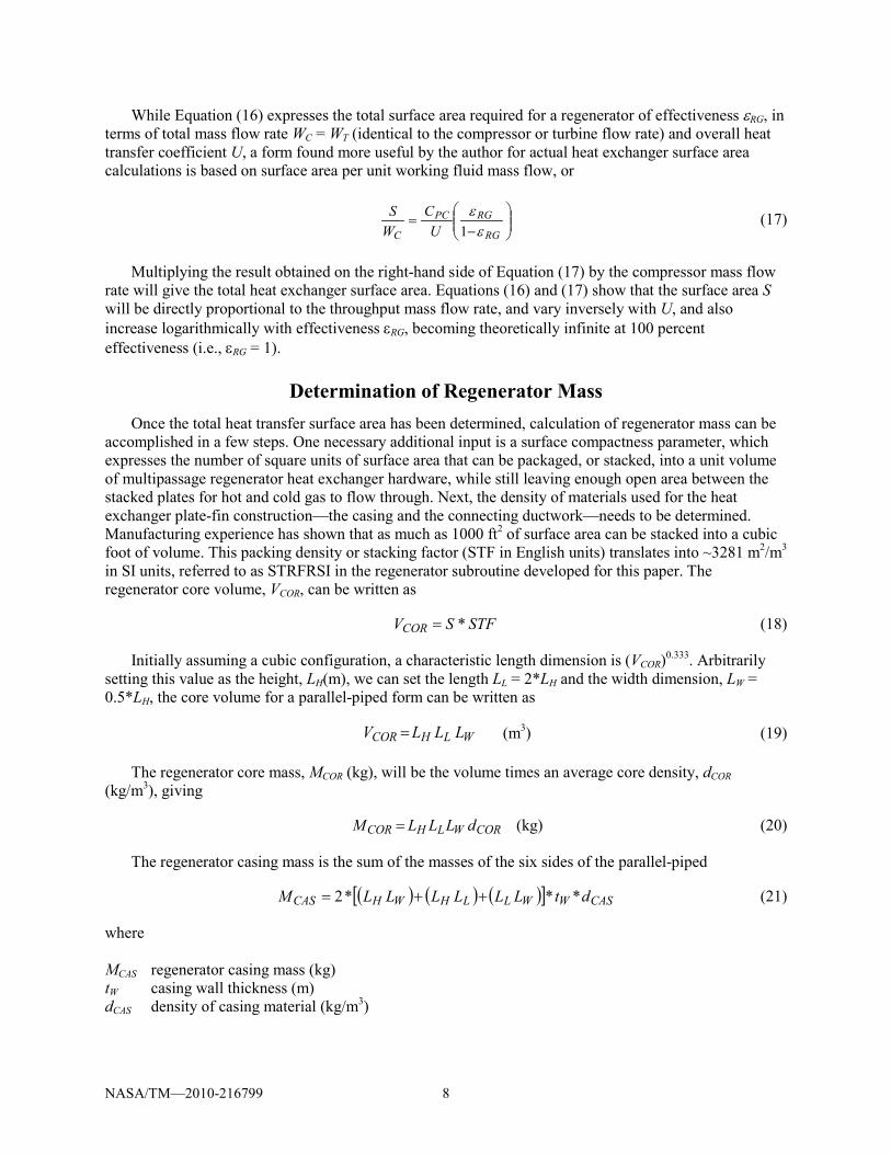
Determination of Regenerator Mass Once the total heat transfer surface area has been determined, calculation of regenerator mass can be
accomplished in a few steps. One necessary additional input is a surface compactness parameter, which expresses the number of square units of surface area that can be packaged, or stacked, into a unit volume of multipassage regenerator heat exchanger hardware, while still leaving enough open area between the stacked plates for hot and cold gas to flow through. Next, the density of materials used for the heat exchanger plate-fin construction—the casing and the connecting ductwork—needs to be determined. Manufacturing experience has shown that as much as 1000 ft2 of surface area can be stacked into a cubic foot of volume. This packing density or stacking factor (STF in English units) translates into ~3281 m2/m3 in SI units, referred to as STRFRSI in the regenerator subroutine developed for this paper. The regenerator core volume, VCOR, can be written as
STFSVCOR *= (18)
Initially assuming a cubic configuration, a characteristic length dimension is (VCOR)0.333. Arbitrarily setting this value as the height, LH(m), we can set the length LL = 2*LH and the width dimension, LW = 0.5*LH, the core volume for a parallel-piped form can be written as
WLHCOR LLLV = (m3) (19)
The regenerator core mass, MCOR (kg), will be the volume times an average core density, dCOR (kg/m3), giving
CORWLHCOR dLLLM = (kg) (20)
The regenerator casing mass is the sum of the masses of the six sides of the parallel-piped
MCAS regenerator casing mass (kg) tW casing wall thickness (m) dCAS density of casing material (kg/m3)
NASA/TM—2010-216799 9
Finally, assuming that the mass of the hot and cold inlet and outlet ducts is 25 percent of casing mass, that is, MDUCT ~ 0.25MCAS, the total regenerator mass MREG becomes
DUCTCASCORREG MMMM ++= (22)
The above equations and procedures were programmed into a subroutine called RGNW of the previously mentioned BRMAPS code, which was then run in a standalone mode to generate the results discussed in the next section. Note that since regenerator effectiveness, εRG , was an input variable for these computations, the procedure to compute εRG for the recommended counterflow or crossflow recuperator configurations for desired Ntu values (Ref. 5) was not required for the subroutine. The procedure is however available as an option in the author’s main program (BRMAPS).
Regenerator Mass Results Numerical results of regenerator mass are shown in Table 1, which is an output by one of the author’s
subroutines on regenerator performance and specific mass, for He working fluid, as a function of regenerator effectiveness (ERG), stacking factor (STFRI), core material density (DENI), and overall heat transfer coefficient (UU). Resulting values are shown in columns 2 and 5, respectively, referring to specific heat transfer area and specific mass. As shown, the first 10 rows of the table are displayed in English and the remaining rows in SI units. The units displayed in column 5 are identical to the SI and English unit portions of the table.
TABLE 1.—REGENERATOR DESIGN COMPARISON IN ENGLISH AND SI UNITS FOR He WORKING FLUID
As a check on the internal dimensional consistency maintained during the calculations, the reader
may easily verify that with constant overall heat transfer coefficients of 25 Btu/ft2-hr-R, which is identical to 142.08 W/m2-K. The numerical specific mass values in column 5 are identical within roundoff error
NASA/TM—2010-216799 10
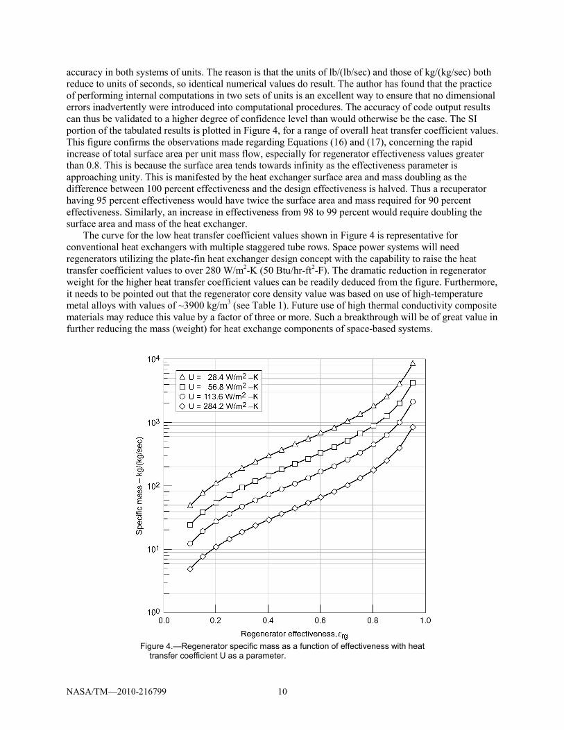
accuracy in both systems of units. The reason is that the units of lb/(lb/sec) and those of kg/(kg/sec) both reduce to units of seconds, so identical numerical values do result. The author has found that the practice of performing internal computations in two sets of units is an excellent way to ensure that no dimensional errors inadvertently were introduced into computational procedures. The accuracy of code output results can thus be validated to a higher degree of confidence level than would otherwise be the case. The SI portion of the tabulated results is plotted in Figure 4, for a range of overall heat transfer coefficient values. This figure confirms the observations made regarding Equations (16) and (17), concerning the rapid increase of total surface area per unit mass flow, especially for regenerator effectiveness values greater than 0.8. This is because the surface area tends towards infinity as the effectiveness parameter is approaching unity. This is manifested by the heat exchanger surface area and mass doubling as the difference between 100 percent effectiveness and the design effectiveness is halved. Thus a recuperator having 95 percent effectiveness would have twice the surface area and mass required for 90 percent effectiveness. Similarly, an increase in effectiveness from 98 to 99 percent would require doubling the surface area and mass of the heat exchanger.
The curve for the low heat transfer coefficient values shown in Figure 4 is representative for conventional heat exchangers with multiple staggered tube rows. Space power systems will need regenerators utilizing the plate-fin heat exchanger design concept with the capability to raise the heat transfer coefficient values to over 280 W/m2-K (50 Btu/hr-ft2-F). The dramatic reduction in regenerator weight for the higher heat transfer coefficient values can be readily deduced from the figure. Furthermore, it needs to be pointed out that the regenerator core density value was based on use of high-temperature metal alloys with values of ~3900 kg/m3 (see Table 1). Future use of high thermal conductivity composite materials may reduce this value by a factor of three or more. Such a breakthrough will be of great value in further reducing the mass (weight) for heat exchange components of space-based systems.
Figure 4.—Regenerator specific mass as a function of effectiveness with heat
transfer coefficient U as a parameter.
NASA/TM—2010-216799 11
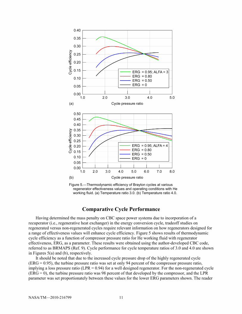
Figure 5.—Thermodynamic efficiency of Brayton cycles at various regenerator effectiveness values and operating conditions with He working fluid. (a) Temperature ratio 3.0. (b) Temperature ratio 4.0.
Comparative Cycle Performance Having determined the mass penalty on CBC space power systems due to incorporation of a
recuperator (i.e., regenerative heat exchanger) in the energy conversion cycle, tradeoff studies on regenerated versus non-regenerated cycles require relevant information on how regenerators designed for a range of effectiveness values will enhance cycle efficiency. Figure 5 shows results of thermodynamic cycle efficiency as a function of compressor pressure ratio for He working fluid with regenerator effectiveness, ERG, as a parameter. These results were obtained using the author-developed CBC code, referred to as BRMAPS (Ref. 9). Cycle performance for cycle temperature ratios of 3.0 and 4.0 are shown in Figures 5(a) and (b), respectively.
It should be noted that due to the increased cycle pressure drop of the highly regenerated cycle (ERG = 0.95), the turbine pressure ratio was set at only 94 percent of the compressor pressure ratio, implying a loss pressure ratio (LPR = 0.94) for a well designed regenerator. For the non-regenerated cycle (ERG = 0), the turbine pressure ratio was 98 percent of that developed by the compressor, and the LPR parameter was set proportionately between these values for the lower ERG parameters shown. The reader
NASA/TM—2010-216799 12
may surmise that an excessively high regenerator pressure loss would negate the increase in cycle efficiency obtained by regeneration. This is indeed a correct conclusion. If the LPR parameter is set to 0.8, implying a 20 percent pressure loss, the efficiency for 95 percent effectiveness would be no higher than that obtained for the non-regenerated cycles.
Regarding Figure 5, note that cycle efficiency is raised considerably as regenerator effectiveness (ERG) is varied from 0, indicating no regeneration, to 0.95 (i.e., 95 percent) at pressure ratios below a certain threshhold, or crossover value, which is ~3.7 for IC (ALFA) = 3.0 and ~5.4 for ALFA = 4.0. Detailed numerical calculations of cycle state point temperatures confirm that the crossover pressure ratios designate conditions at which the turbine exit gas temperatures (TOT) are exactly equal to temperatures at the compressor discharge, and thus, there is no heat transfer from the turbine discharge gas stream to the compressor stream. Hence, all cycles will have the same efficiency, regardless of regenerator effectiveness. For pressure ratios above the crossover value, the efficiency of the nonregenerated cycle will exceed that of the regenerated cycles with the highest effectiveness regenerator incurring the largest efficiency penalty.
Additional observations that can be gleaned from Figure 5 show that the pressure ratio at which the highest cycle efficiency is obtained becomes progressively lower with increasing effectiveness (εRG = ERG). Thus, for a cycle temperature ratio of 3.0 (Fig. 5 (a)), the optimum pressure ratio is approximately 1.8 for an εRG of 0.95, yielding an efficiency of about 0.36 (i.e., 36 percent). But for the lower ERG value of 0.80 the pressure ratio optimum rises to ~2.20, at which an efficiency of only 30 percent is obtained. The reader may also note that as the cycle temperature ratio is raised to 4.0, efficiency values increase by ~10 percent and the optimum pressure ratios shift to the right by increments that are in inverse relation to the ERG value. The increase in cycle efficiency between the non-regenerated case (ERG = 0) and the highest regenerated cycle (ERG = 0.95) at the optimum pressure ratios for each is about 10 percent for each temperature ratio. Note that tradeoff studies of cycle efficiency versus regenerator mass also need to take into account that, whereas centrifugal turbomachinery may be sufficient for the relatively low pressure ratios required for highly regenerated cycles, the higher optimum pressure ratios for the non-regenerated machines may require multistage axial turbines and compressors. These, however, have a higher component (i.e., polytropic) efficiency, which may significantly reduce or even negate the efficiency advantage of regenerated cycles. Detailed tradeoff studies will require accurate performance turbomachine specifications.
Concluding Remarks A computational procedure for the determination of CBC (closed Brayton cycle) recuperator mass
and an accompanying computer subroutine were developed for incorporation in a previously written gas turbine code. Relevant equations were derived for computing the total heat exchanger surface area requirements as a function of overall heat transfer coefficient, plate-fin material thermal conductivity, and gas turbine mass flow rate. Relevant results on recuperator mass per unit CBC flow rate (in kg/(kg/sec) or lb/(lb/sec)) as a function of effectiveness with overall heat transfer coefficient as a parameter were shown (Fig. 4). As expected, as effectiveness values approach unity, or 100 percent, the required surface area and hence, heat exchanger mass tends toward infinity since heat transfer at near-zero temperature difference is implied. The beneficial effect of regeneration on CBC thermodynamic efficiency was also shown (Fig. 5), especially for low-cycle pressure ratios, where the temperature of the turbine exit flow significantly exceeds that of the compressor. The requirement for low regenerator pressure loss (<6 percent) was also implied in the results shown in Figure 5.
Comparison of Figures 4 and 5 should permit meaningful tradeoff studies on the efficacy of regeneration for selected operating conditions. To verify the dimensional accuracy of the regenerator mass computational procedure, all calculation steps for a regenerator’s specific mass, that is, heat exchanger weight per unit working fluid mass flow are performed in both English and SI units. Identical numerical values for the specific mass parameter, whether expressed in lb/(lb/sec) or kg/(kg/sec), show the dimensional consistency of overall results.
pp. 491–500, 1941. 2. McDonald, C.F.: “The Key Role of Heat Exchangers in Advanced Gas Cooled Reactor Plants,” Heat
Recovery Systems & CHP, Vol. 14, No. 1, pp. 7–24, 1994 3. Juhasz, A.J., Rarick, R.A., and Rangarajan, R.: “High Efficiency Nuclear Power Plants using Liquid
Fluoride Thorium Reactor Technology,” AIAA Paper 2009–4565. Presented at the 7th IECEC, Aug. 2–5, 2009, Denver, CO.
4. Zucrow, M.J.: “Aircraft and Missile Propulsion-Vol. II,” John Wiley & Sons Inc., New York, 1958. 5. Kays, W.M. and London A.L.: “Compact Heat Exchangers,” McGraw-Hill Book Company, Inc.,
1984. 6. McAdams, W.H.: “Heat Transmission,” McGraw-Hill Book Company, Inc., 1954. 7. Sparrow, E.M. and Liu, C.H.: “Heat Transfer, Pressure Drop and Performance Relationship for In-
Line, Staggered and Continuous Plate Heat Exchangers,” Int. Journal of Heat & Mass Transfer, Vol. 22, pp. 1613–1625, 1979.
8. Sunden, B. and Faghri, M., eds.: “Heat Transfer in Gas Turbines,” MIT Press, Boston, 2001. 9. Juhasz, A.J.: “Analysis and Numerical Optimization of Gas Turbine Space Power Systems with
Nuclear Fission Reactor Heat Sources,” Doctoral Dissertation, Cleveland State University, May 25, 2005.
10. Juhasz, A.J.: “Multi-Megawatt Gas Turbine Power Systems for Lunar Colonies,” NASA/TM—2006-214658, Dec. 2006.
REPORT DOCUMENTATION PAGE Form Approved
OMB No. 0704-0188 The public reporting burden for this collection of information is estimated to average 1 hour per response, including the time for reviewing instructions, searching existing data sources, gathering and maintaining the data needed, and completing and reviewing the collection of information. Send comments regarding this burden estimate or any other aspect of this collection of information, including suggestions for reducing this burden, to Department of Defense, Washington Headquarters Services, Directorate for Information Operations and Reports (0704-0188), 1215 Jefferson Davis Highway, Suite 1204, Arlington, VA 22202-4302. Respondents should be aware that notwithstanding any other provision of law, no person shall be subject to any penalty for failing to comply with a collection of information if it does not display a currently valid OMB control number. PLEASE DO NOT RETURN YOUR FORM TO THE ABOVE ADDRESS.
1. REPORT DATE (DD-MM-YYYY) 01-09-2010
2. REPORT TYPE Technical Memorandum
3. DATES COVERED (From - To)
4. TITLE AND SUBTITLE A Mass Computation Model for Lightweight Brayton Cycle Regenerator Heat Exchangers
5a. CONTRACT NUMBER
5b. GRANT NUMBER
5c. PROGRAM ELEMENT NUMBER
6. AUTHOR(S) Juhasz, Albert, J.
5d. PROJECT NUMBER
5e. TASK NUMBER
5f. WORK UNIT NUMBER WBS 199008.02.03.0663.09
7. PERFORMING ORGANIZATION NAME(S) AND ADDRESS(ES) National Aeronautics and Space Administration John H. Glenn Research Center at Lewis Field Cleveland, Ohio 44135-3191
8. PERFORMING ORGANIZATION REPORT NUMBER E-17357-1
9. SPONSORING/MONITORING AGENCY NAME(S) AND ADDRESS(ES) National Aeronautics and Space Administration Washington, DC 20546-0001
10. SPONSORING/MONITOR'S ACRONYM(S) NASA
11. SPONSORING/MONITORING REPORT NUMBER NASA/TM-2010-216799
12. DISTRIBUTION/AVAILABILITY STATEMENT Unclassified-Unlimited Subject Categories: 37 and 64 Available electronically at http://gltrs.grc.nasa.gov This publication is available from the NASA Center for AeroSpace Information, 443-757-5802
13. SUPPLEMENTARY NOTES
14. ABSTRACT Based on a theoretical analysis of convective heat transfer across large internal surface areas, this paper discusses the design implications for generating lightweight gas-gas heat exchanger designs by packaging such areas into compact three-dimensional shapes. Allowances are made for hot and cold inlet and outlet headers for assembly of completed regenerator (or recuperator) heat exchanger units into closed cycle gas turbine flow ducting. Surface area and resulting volume and mass requirements are computed for a range of heat exchanger effectiveness values and internal heat transfer coefficients. Benefit cost curves show the effect of increasing heat exchanger effectiveness on Brayton cycle thermodynamic efficiency on the plus side, while also illustrating the cost in heat exchanger required surface area, volume, and mass requirements as effectiveness is increased. The equations derived for counterflow and crossflow configurations show that as effectiveness values approach unity, or 100 percent, the required surface area, and hence heat exchanger volume and mass tend toward infinity, since the implication is that heat is transferred at a zero temperature difference. To verify the dimensional accuracy of the regenerator mass computational procedure, calculation of a regenerator specific mass, that is, heat exchanger weight per unit working fluid mass flow, is performed in both English and SI units. Identical numerical values for the specific mass parameter, whether expressed in lb/(lb/sec) or kg/(kg/sec), show the dimensional consistency of overall results. 15. SUBJECT TERMS Heat exchangers; Regenerators; Recuperators
16. SECURITY CLASSIFICATION OF: 17. LIMITATION OF ABSTRACT UU
18. NUMBER OF PAGES
19
19a. NAME OF RESPONSIBLE PERSON STI Help Desk (email:[email protected])
a. REPORT U
b. ABSTRACT U
c. THIS PAGE U
19b. TELEPHONE NUMBER (include area code) 443-757-5802
Standard Form 298 (Rev. 8-98)Prescribed by ANSI Std. Z39-18