A Method for Constructing Automotive Cybersecurity Tests, a CAN Fuzz Testing Example
Fowler, DS, Bryans, J, Cheah, M, Wooderson, P & Shaikh, S Author post-print (accepted) deposited by Coventry University’s Repository Original citation & hyperlink:
Fowler, DS, Bryans, J, Cheah, M, Wooderson, P & Shaikh, S 2019, A Method for Constructing Automotive Cybersecurity Tests, a CAN Fuzz Testing Example. in 2019 IEEE International Conference on Software Quality, Reliability and Security Companion (QRS-C). IEEE Computer Society, IEEE International Conference on Software Quality, Reliability and Security Companion , Sofia, Bulgaria, 22/07/19. https://dx.doi.org/10.1109/QRS-C.2019.00015
Abstract—There is a need for new tools and techniques toaid automotive engineers performing cybersecurity testing onconnected car systems. This is in order to support the principleof secure-by-design. Our research has produced a method toconstruct useful automotive security tooling and tests. It has beenused to implement Controller Area Network (CAN) fuzz testing (adynamic security test) via a prototype CAN fuzzer. The black-boxfuzz testing of a laboratory vehicle’s display ECU demonstratesthe value of a fuzzer in the automotive field, revealing bugs in theECU software, and weaknesses in the vehicle’s systems design.
Index Terms—cybersecurity testing, controller area network,fuzz testing, automotive engineering, systems security, embeddedsystems, dynamic software testing, black-box testing, SAE J3061
I. INTRODUCTION
At Black Hat 2015, the premier convention for hackers,security researchers Miller and Valasek showed the first remoteexploitation and control of an unmolested mass productioncar [1]. Their research provided a demonstration of cyber-physical hacking that could potentially cause harm to thevehicle’s occupants, other road users, and pedestrians. Theirwidely reported research once again showed that any type ofdevice that has connectivity could become a target for a cyber-attack and highlighted the potentially severe consequences ofa compromised connected car. If car manufacturers were notalready addressing the cybersecurity of their products, thentheir research showed the importance of doing so.
The automotive industry is responding to the cybersecuritythreat to their products. In the SAE J3061 guidelines [2] theuse of Threat Analysis and Risk Assessment (TARA) anddesigning security into systems is advocated. The goal ofsecure-by-design [2]–[4] is to raise assurance levels [4], [5]in the software and hardware within vehicle systems. Highassurance is important in order to maintain confidence [5] ina connected car’s operation and safety.
Jointly funded by Coventry University and HORIBA MIRA Limited.
The secure-by-design goal is verified with security test-ing [2], [4]. One of the goals of our research is to examinehow a class of security testing, called fuzz testing, can havean impact on the automotive systems engineering field. Fuzztesting is a successful dynamic security testing technique usedin traditional information systems [7]. However, there is ascarcity of detailed published works in the application of fuzztesting to vehicle systems [6].
Within vehicle systems several types of data networks areused, here, the Controller Area Network (CAN) is chosen asthe target for fuzz testing, for several reasons [6]:
• it is a commonly used in-vehicle network;• many of the computers in a vehicle have a CAN interface;• the design of CAN makes it very susceptible to attack;• tools and techniques for manipulating the CAN protocol
are inexpensive and readily available.
In our research we examine how a new, easy to use, andeasy to install prototype automotive fuzz testing tool, a CANfuzzer, can be used to test the security properties of a vehicle’scomputers.
An in-vehicle computer is commonly called an ElectronicControl Unit (ECU). In our research a laboratory vehicle’sdisplay ECU is used as the Target of Evaluation (ToE) [8],a.k.a. the system-under-test. The results from the fuzz testingfound weaknesses in the display ECU and the associated labvehicle’s systems design. Additional engineering to addressthe discovered weaknesses would improve the assurance ofthe target vehicle against CAN based attacks.
The work presented here builds upon our previously pub-lished work, see Section II. In Section III a brief refresher onthe CAN protocol is given. Section IV adds our methodologyfor constructing automotive security tests and its application toCAN fuzz testing. The new results from fuzz testing a displayECU are covered in Section V, this is followed by a discussionin Section VI and a conclusion in Section VII.
II. PREVIOUS WORK
In our previous work [6] we examined the use of fuzz testingwithin the automotive field. Fuzz testing is used by securityresearchers, software testers and attackers. The aim of fuzztesting is to discover software and hardware issues that maythen be used to compromise a system’s security properties, itsconfidentiality, integrity, and availability.
Fuzz testing is a dynamic software stress test (equivalentto injecting noise into computer electronics when performinghardware fault injection tests):
1) High volumes of random or malformed data are sentinto the system’s interfaces by a fuzzer.
2) The system’s reaction to the fuzz testing is monitored.3) Conditions at a point of failure or interest are recorded
for analysis.4) Fuzz testing is highly automated for efficiency, and to
cover a wide value space.5) Analysis of fuzz testing results may reveal a system’s
weaknesses.6) An attacker will use weaknesses to try and compromise a
system. A software tester will use the results to improvesystem design, and hence a system’s assurance levels.
Automotive fuzzers are summarised in Table I. The be-Storm [9] and Defensics [10], [11] fuzzers are general purposecommercial products. The booFuzz [12] fuzzer is open sourcebut was configured to work with commercial software. ThePeach fuzzer is advertised as supporting automotive use,but there are no published results or use cases available.There is an open source version of Peach available. Mostof the approaches to fuzz testing are based upon protocolinformation, i.e. based upon knowledge derived from networkor interface specifications. For automotive CAN this meansusing the format of the CAN data packets, see Section III. Thisis common for black box testing, performed in our research,where little is known about the system internals. However, awhite box approach can also be used, for example, if there ispre-existing knowledge of CAN data packet contents acquiredfrom source code running in an ECU. The complex features,functionalities, and algorithms of the existing commercialfuzzers will the subject of further research.
The addition to Table I from its previous publication is theinteresting solution to the oracle problem provided by [11].They propose fuzz testing a ToE alongside an identical system(not subjected to the fuzz testing) as a reference point, andcomparing the output from the fuzzed ToE to the reference
system. This proof-of-concept system uses two model cars,one as the ToE and one as the reference, with the models’systems controlled by CAN busses. A dSPACE Hardware-in-loop (HIL) system is linked to the Defensics fuzzer. (HIL,software-in-the-loop, and model-in-the-loop, are methods usedto emulate systems and components during automotive devel-opment.) The dSPACE HIL can load, start and stop the fuzzer.When the fuzzer is active the measured analog and digitalsignals from the two models are compared and any differencesare logged as errors.
Information on the performance of the system would beuseful, for example, does the analysis of the outputs keep upwith system operation? Further, there is no discussion of theacceptable variation between the ToE and the reference system.How much of a difference between the output of the fuzztested ToE and the reference system is required before an errorcondition is considered? An interesting point is made aboutthe reference systems. If a model of the system can run onthe HIL, and the model is accurate, then the reference systemcould be virtual, used within the HIL system itself.
As we have previously noted in our own research [6], theyalso mention the lack of available knowledge on automotivefuzz testing. Most publications are overview experiences ofimplementing a commercial fuzzer, rather than detailed data onthe effectiveness of the fuzz testing, the practical experimentalmethods used, and lessons to be learnt from the experiences.There is a need, and opportunity, to add to the fuzz testingknowledge in the automotive field. This lack of knowledgedoes not only apply to CAN. There are many technologies inuse in a vehicle, the large attack surface provides plenty ofscope for more research into applying fuzz testing to vehiclesystems. This motivates our research to address the gaps.
III. THE CAN BUS
There is plenty of publicly available information on thetechnical details of the CAN bus, the following is a briefoverview.
Fig. 1. Overview of a CAN data packet. The software in an ECU or fuzzersees the CAN data as an id, data length, data byte values and status condition.The CAN network hardware handles the control bits during data transmissionand reception.
CAN uses twisted-pair wires to provide a data networkbetween ECUs in a car. The transmission speed of the standardCAN protocol is modest, designed to support up to 1Mb/s. Asimplified CAN data packet is shown in Fig. 1. The CANhardware in an ECU handles the details of the data protocol,including error handling. The ECU software views the CAN
packet as an identifier, data length, payload bytes and networkstatus information. Any ECU can initiate data transmission,however, only one ECU at a time is allowed to transmit.For a CAN packet the arbitration identifier (id), determinestransmission priority. The lowest id continues transmission inthe event of packet collision (two or more ECUs attemptingsimultaneous transmission). Examples of CAN packets loggedfrom the lab vehicle are shown in Table II. CAN was designedprior to vehicle connectivity and without consideration forcybersecurity. It has vulnerabilities and is susceptible to severaltypes of attack [15], including packet sniffing and replay,injecting false values, denial of service via flooding, jamming(known as bus-off) and spoofing data from ECUs.
IV. A METHOD FOR CONSTRUCTING AUTOMOTIVESECURITY TESTS
Our research has identified seven phases in the developmentof an automotive security testing technique, shown in Fig. 2.
1) Establishment and validation of a test environment -The complexity and costs of the modern vehicle providesa challenging environment in which to develop newsecurity testing methods. For a new vehicle design theaccess to the car’s internal systems and components maynot be possible in the early stages. The use of a testingenvironment, in the form of a reusable testbed, providesa controlled setting for developing new security testingmethods. In our research a commercial vehicle designand development system is deployed as a security testingrig. Such systems are traditionally used for functionaltesting, but our research [14] confirms they can beused for the development of security tooling, a similarapproach taken by other researchers [11]–[13].
2) Determine a security test to develop or perform -SAE J3061 identifies three classes of security test thatcan be executed against a vehicle system or component.
The outcome of this phase is for the researcher tochoose one of vulnerability, fuzz, or penetration testing.However, each of these three tests will have specifictesting requirements based upon the technology of theToE (see the next phase), for example a penetration testfor a WiFi interface would differ in its details to onetargeted at Bluetooth.
3) Determine the technology/ToE to test - Vehicles con-tain multiple digital technologies. There are many typesof components, sensors, interconnections, interfaces, andcommunication protocols. For this research CAN waschosen for its ubiquity within vehicle systems. However,many vehicle technologies require new research onsecurity testing techniques.
4) Development of the test tooling - To execute the cho-sen security test against the chosen technology toolingsupport is required. In testing digital systems this in-variably means some form of software, but may includeinterfacing and measurement equipment. The softwareand equipment can be commercially sourced, or mayrequire bespoke design and development, or both. Thisresearch required a simple CAN fuzzer. Simplicity hereis in terms of ease of use and deployment. Our previouswork [6] discusses the development of the prototypeCAN fuzzer. It uses off-the-shelf hardware to interface toCAN. The testbed provided the controlled environmentto enable the development of the tooling. It is anticipatedthat developing specialised tooling for other vehicletechnologies will be required.
5) Validation of the tooling - Any security test toolingwill need to be performant for its intended application.Therefore, it needs to be validated. In this researchvalidation of the CAN fuzzer was performed during itsdevelopment. A similar validation phase is required forsecurity tooling used against other technologies. Issueswith validation results in further tooling development.
6) Experimental methods using the tooling - In this phasethe established test environment and the new test toolingis used, performing the determined security test andrecording the results. However, the lack of knowledgein security testing of vehicle systems means that theexperimental methods will require refining as testingexperience is gained. For example, the experimentaluse of the prototype CAN fuzzer revealed unforeseenissues. Thus, as well as evaluating the results of theexperiments, it is important to refine the experimentaltechniques used, this requires the next phase.
7) Method and tooling improvements - The final phase isused to improve the effectiveness of the security testingmethods and tooling against the targeted technologies.Use of the security tooling can suggest, or require,improvements for future experiments, security tests anduse cases. This improvement is illustrated by the dashedline in the schematic in Fig. 2. The near continuousdevelopment of new and improved technologies in theautomotive field will, likewise, require continuous im-
provements in security testing tooling and techniques.The method, summarised in Fig. 2, for the construction of
automotive security tests and tooling, was derived from ourwork on producing a prototype CAN fuzzer tool. The methodapplied to CAN fuzz testing is summarised in Figure 3.
Fig. 3. CAN fuzz testing development method.
The implemented prototype CAN fuzzer is a simple toinstall Windows PC application. The fuzzer communicateswith CAN using a PEAK System1 USB to CAN interface. Noother expensive software, special packages, or specific versionsof libraries are required. It has several Graphical User Interface(GUI) screens for configuring the CAN interfaces, fuzz testingand logging. One of the screens in shown in Fig. 4.
Fig. 4. One of the prototype CAN fuzzer’s configuration screens.
Having used the prototype CAN fuzzer against ToEs inour previous work, here it was deployed against a vehicle’sdisplay ECU. As well as allowing for an examination of theECUs security properties (Section II), it provides for furtherrefinement of the fuzzer, i.e. stage 7. of the method.
Aside from the display ECU having a CAN interface, itsscreen was a factor in its choice as a ToE. It had been noted inour research that a problem with fuzz testing vehicle systemsis the cyber-physical aspect – the software side of a ToE mayinduce changes on the physical side. A CAN data packet maynot cause a detectable reaction from an ECU via a CAN busreply. This is because the CAN packet is triggering an external,real world response. Experimenting on an ECU with a built-in real world, and visible, aspect allows for testing that is notreliant upon other vehicle parts, such as sensors, actuators orlights.
1https://www.peak-system.com/
V. RESULTS FROM FUZZ TESTING A DISPLAY ECUThe target Display Interface (DI) ECU operating in the lab
vehicle is shown in Fig. 5. It’s position within the vehiclesCAN networks is illustrated in Fig. 6, derived from the vehicleelectrical service manual. The functions of the vehicle’s ECUsare listed in Table III.
Fig. 5. The Display Interface (DI) ECU in the laboratory vehicle, a varietyof messages are displayed in response to occupants operating the vehicle.
Fig. 6. Networks connecting ECUs in the lab vehicle, 3 High Speed (HS)CAN busses run at 500Kbps, and one Medium Speed (MS) CAN at 125Kbps.
TABLE IIIECUS IN A SMALL VEHICLE
ECU Reference ECU Functiona
OBD On-Board Diagnostics connectorIP Instrument panelPS Power steering control
ABS Anti-lock brake systemTC Transmission controlPC Powertrain control
TP/SM Tire pressure and security moduleBC Body controlDI Display interface
GPS Global positioning systemAC Audio control
aAbbreviations changed for commercial confidentiality.
In our experience fuzz testing may damage components andso another display ECU was purchased for the experiment.The purchased ECU does not have the full color display butfunctions correctly within the vehicle, see Fig. 7. The ECU’sinternal CAN connection was confirmed to run at 500Kbps,and the observed CAN packets have an eight-byte payload.
Fig. 7. The ECU obtained for bench testing operating in the lab vehicle.Despite ordering the correct used unit, it is a lower specification component(there is a small difference in the part numbers), it does functions correctly.
For the bench-based fuzz testing, custom cabling, correctlyterminated2, was used to connect to the PC based CAN fuzzer.A bench supply, to power the ECU, replicated the 12.4 voltsthat was measured at the vehicle.
The fuzzer was configured to randomise the standard CANid range from 0 to 2047. At the fuzzer’s default transmissionrate of one packet per millisecond, it would take less than threeseconds to run through the standard range of id values (2048 ·0.001s = 2.048s). The CAN packet payload was configuredto be fixed at eight bytes, as observed on the car’s CAN bus.The byte values were randomised over their full range of 0 to255.
It was observed that the display ECU, as with other ECUsthat have been tested, enters a standby mode when no CANcommunications are present on the CAN bus. This can causethe CAN fuzzer to report communications errors. This isbecause the initial CAN packet transmission from the fuzzerdoes not get acknowledged, due to the ECU waking from itsstandby mode. If the ECU does not wake up quickly enoughthen the fuzzer’s CAN interface can enter what is known asa bus-off state. To overcome this problem a second CANinterface is configured within the CAN fuzzer and attachedto the CAN bus. This second interface allows for the initialCAN packets from the fuzzer to be acknowledged, while theECU awakens from standby. This prevents the possible bus-offstate.
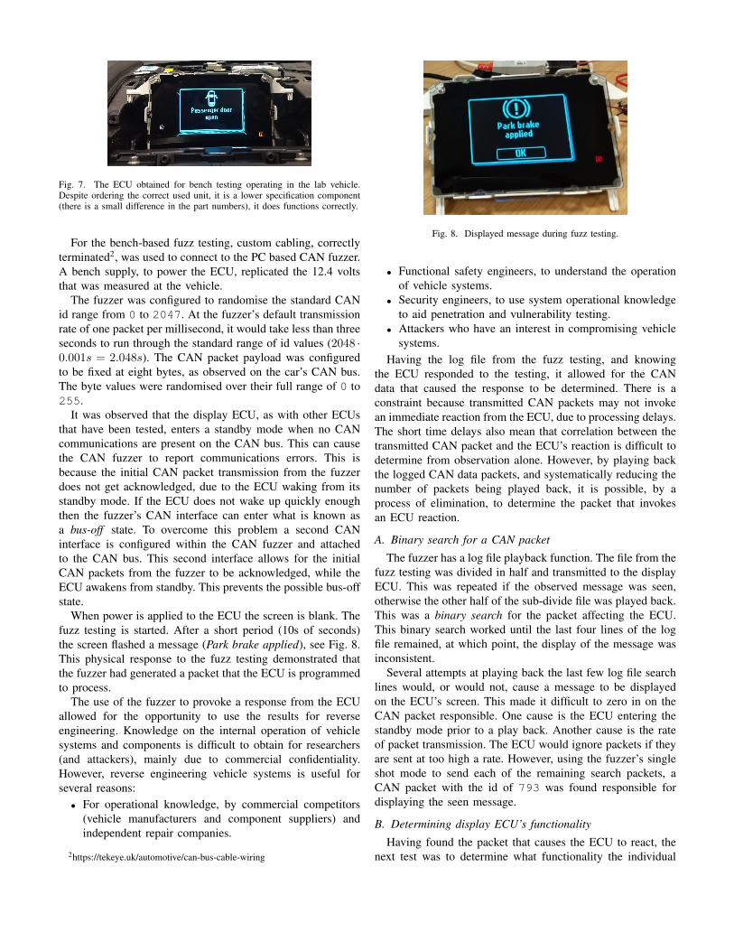
When power is applied to the ECU the screen is blank. Thefuzz testing is started. After a short period (10s of seconds)the screen flashed a message (Park brake applied), see Fig. 8.This physical response to the fuzz testing demonstrated thatthe fuzzer had generated a packet that the ECU is programmedto process.
The use of the fuzzer to provoke a response from the ECUallowed for the opportunity to use the results for reverseengineering. Knowledge on the internal operation of vehiclesystems and components is difficult to obtain for researchers(and attackers), mainly due to commercial confidentiality.However, reverse engineering vehicle systems is useful forseveral reasons:
• For operational knowledge, by commercial competitors(vehicle manufacturers and component suppliers) andindependent repair companies.
• Functional safety engineers, to understand the operationof vehicle systems.
• Security engineers, to use system operational knowledgeto aid penetration and vulnerability testing.
• Attackers who have an interest in compromising vehiclesystems.
Having the log file from the fuzz testing, and knowingthe ECU responded to the testing, it allowed for the CANdata that caused the response to be determined. There is aconstraint because transmitted CAN packets may not invokean immediate reaction from the ECU, due to processing delays.The short time delays also mean that correlation between thetransmitted CAN packet and the ECU’s reaction is difficult todetermine from observation alone. However, by playing backthe logged CAN data packets, and systematically reducing thenumber of packets being played back, it is possible, by aprocess of elimination, to determine the packet that invokesan ECU reaction.
A. Binary search for a CAN packet
The fuzzer has a log file playback function. The file from thefuzz testing was divided in half and transmitted to the displayECU. This was repeated if the observed message was seen,otherwise the other half of the sub-divide file was played back.This was a binary search for the packet affecting the ECU.This binary search worked until the last four lines of the logfile remained, at which point, the display of the message wasinconsistent.
Several attempts at playing back the last few log file searchlines would, or would not, cause a message to be displayedon the ECU’s screen. This made it difficult to zero in on theCAN packet responsible. One cause is the ECU entering thestandby mode prior to a play back. Another cause is the rateof packet transmission. The ECU would ignore packets if theyare sent at too high a rate. However, using the fuzzer’s singleshot mode to send each of the remaining search packets, aCAN packet with the id of 793 was found responsible fordisplaying the seen message.
B. Determining display ECU’s functionality
Having found the packet that causes the ECU to react, thenext test was to determine what functionality the individual
bytes in the CAN packet perform. The identified packet haseight bytes of data. Testing the effect of the byte values canbe done in different ways:
1) Treat the individual bits in a byte as flags. Testinginvolves setting and clearing different bits in each ofthe packet’s bytes.
2) Treat the data bytes as integer numbers and incrementthe values from 0 to 255.
3) Generate random values over a byte’s range from 0 to255.
For 2) and 3) there is a combinatorial explosion problem.For an eight byte data packet, with eight bits per byte, the 64bits give 264 value combinations, or nearly 18.5 Exa (Exa =1018) possible values. Thus, methods to simplify the searchof the value space for the meaning of a CAN packet’s bytevalues are required.
One method is to view the packet contents as individualbit flags. This vastly reduces possible combinations by testingeach bit individually. This bit setting was chosen for itssimplicity, testing the 64 packet bits using this method:
1) At the start, data bytes in the CAN packet are zeroed.2) The CAN packet is transmitted to the display ECU.3) The display ECU’s screen is observed for any reaction.4) Each bit is set to one in order (starting at the first bit in
the first byte).5) If the last bit has been set then finish, otherwise go to
step 2.To aid with the single bit testing the prototype CAN fuzzer’s
single shot functionality was modified to make it easy toincrement the byte values, see Fig. 9.
Fig. 9. The CAN fuzzer’s single shot packet functionality was modified toaid with testing the display ECU. The arrows next to each byte increment ordecrement the value by one (values can be entered directly).
The setting of individual bits within the CAN packet (id793) did result in messages being displayed. The results forthe first two bytes are shown in Table IV, space restrictionsprevent all the results being included.
The messages found were compared to the messages listedin the user manual for the car, available from the manufac-turer’s customer website (the reference has been redacted dueto commercial disclosure reasons). The user manual lists 78possible messages that the display may show. Some of the
TABLE IVDISPLAY ECU CAN PACKET ID 793 BIT SETTING RESULTS FOR BYTES 1
AND 2, ALL THE OTHER 5 BYTES WERE SET TO ZERO
Byte 1 Byte 2 Message0000 0000 0000 0000 none (blank screen)0000 0001 0000 0000 Press brake and clutch to start0000 0010 0000 0000 Press brake to start0000 0100 0000 0000 Press clutch to start0000 1000 0000 0000 Active City Stop Auto braking0001 0000 0000 0000 Active City Stop not available0010 0000 0000 0000 Active City Stop Sensor blocked Cle. . .0100 0000 0000 0000 Check tyre pressures1000 0000 0000 0000 Tyre pressure sys malfunction Servic. . .0000 0000 0000 0001 Engine on OK (not in manual)0000 0000 0000 0010 MyKey active Drive safely0000 0000 0000 0100 MyKey Speed limited to 160 km/h)0000 0000 0000 1000 MyKey vehicle at top speed0000 0000 0001 0000 none0000 0000 0010 0000 none0000 0000 0100 0000 none0000 0000 1000 0000 none
possible messages relate to options and equipment that maynot be present due to the vehicle model.
For packet 793, out of the total 64 bit positions, there are22 bits that result in a message being displayed. However,the message Park brake applied was seen twice. Furthermore,two messages are not present in the user manual (Engine onOK and Selector lever unlocked). Therefore, the bit testingfor CAN id 793 revealed 20 of the 78 messages listed in themanual.
The CAN fuzz testing, packet discovery, binary search andbit setting was repeated to find another CAN packet, id 752,that controls the display ECU. For the second round of testingthe previously found id, 793 was excluded from the fuzztesting, by entering it into an exclusion list in the fuzzer (seeFig. 4). Fig. 10 shows one of the messages displayed by packet752.
Fig. 10. The CAN data sent to the display ECU is manipulated to reverseengineer the ECU’s functionality.
For packet 752, out of a total of 64 bit positions, thereare 55 bits that result in a message. However, not all 55 bitpositions result in a unique message. Two messages that aredisplayed via CAN packet 752 are also displayed by CANpacket 793. Two messages are repeated by a bit in differentbytes. One message is not listed in the user manual, whilst in
three messages the text is not identical to the messages in theuser manual. Two messages are repeated by several bits.
Taking the results from the bit testing, and excludingrepeated messages, and the one unlisted message, then at least44 messages in the user manual are displayed via CAN packet752. This means that CAN packets 752 and 793 can display64 of the 78 messages listed in the user manual, suggestingthat one or more additional packets could be responsible forthe remaining messages, see the Discussion in Section VI.
C. Varying CAN packet data byte length
The technique to discover the display ECU’s functionalitywas proving successful. One variable that had not been alteredwas the length of the payload data. This was tried against thetwo discovered packet ids, 793 and 752. The following methodis used to test the variation in the data length.
1) The CAN fuzzer’s single shot function was configuredto transmit CAN packets 793 and 752 to the displayECU.
2) The data length of the CAN packet was varied from themaximum of 8 to the minimum of 0.
3) All the data values were fixed at zero. These Values wereknown not to cause the display of a message.
4) The display ECU was observed for a reaction when theconfigured CAN packets were transmitted.
Varying the data length had an unexpected effect, the resultsare shown in Table V. When the data length is set to 8, withall bytes set to a value of zero, the display ECU does not showany messages. This is expected and was seen in the bit settingexperiments. However, reducing the payload data length doesresult in messages being displayed, even though the bytesvalues are all zero. As the number of bytes in the payloaddecreases the messages beginning displayed changed, in somecases several messages are seen. In Table V the values thatwould have resulted in the seen messages have been enteredin bold red and underscored, with the actual zeroed and sentdata entered in blue. What the results indicate is that thedisplay ECU’s program always reads eight full bytes from adata buffer. This appears to be a classic buffer overflow error.Such a finding, if found prior to production, would requirea bug report to be raised. The software in the ECU shouldignore any message not of the correct length.
VI. DISCUSSION
On first appearances the display ECU appears to be simplein operation, a screen for communicating status messages tothe vehicle occupants. However, there is a degree of complex-ity. It was observed that packet transmission rates influenceits operation. Furthermore, the vehicle’s user manual shows78 possible messages, but many of them would only be seenif a fault occurs or certain vehicle options are fitted (e.g. amanual transmission compared to an automatic transmission).Experimental use of the CAN fuzzer was able to reveal thedata required to display the messages, and other operationalcharacteristics that would have otherwise remained hidden, thiscould be useful to an attacker.
TABLE VUNEXPECTED MESSAGES WERE DISPLAYED WHEN THE CAN PACKET
DATA LENGTH WAS DECREASED FROM THE OBSERVED 8 BYTES.
Reverse engineering of ECU functionality is needed todetermine how systems work. System knowledge is useful tohackers, pen testers, functional safety engineers, rival manu-facturers, and parts suppliers. The reverse engineering of thedisplay ECU could be continued. Indeed, another run of thefuzz testing, with the found ids excluded, found a CAN packetwith id 753 responsible for an additional 4 messages. However,the focus of our research is not to fully reverse engineer acomponent, as the primary aim is to determine the usefulnessof fuzz testing to improve automotive systems assurance levels.To that end the results from testing against the ECU haveprovided useful evidence to support the use of automotive fuzztesting. Furthermore, the results were used to inject unexpectedmessages into the lab vehicle.
A. Injecting display ECU messages
One aim of security experiments is to learn enough abouta component in order to use the knowledge to compromise avehicle. In doing so it provides evidence needed to improvethe component design, system design and mitigate the attack.
For the display ECU the knowledge to control what is shownto vehicle occupants is useful for attackers. In this case itallows for the display of incorrect messages to the vehicleusers, including messages that may not be understood becausethey are not in the user manual. Displaying those messageswould be disturbing in a variety of situations.
It can be seen, Fig. 6, that the display ECU is not con-nected to the On-Board Diagnostics (OBD) port, a commonentry when attacking vehicle CAN busses. Thus, the CANpackets needed to display a rogue message must be sent via aconnection to the vehicle’s internal CAN bus. This is achievedusing a man-in-the-middle connection close to another ECUunder the dashboard, see Figure 11.
Thus, the message injection is not as straightforward as itcould be. However, access to the network is not difficult andcertainly possible by someone who is knowledgeable. There is
Fig. 11. Splicing into the lab’s vehicle’s internal CAN network via an AudioInterface Module (AIM) ECU located below the dashboard. This provided anaccess point for injecting invalid CAN data.
the argument that if physical access is required then some otherattack would be performed. However, the principles behind thediscovery of the display ECU functionality, and the messageinjection, are applicable to future security testing. Furthermore,there are multi-stage scenarios in which a similar, or the same,type of attack would be useful to certain adversaries, forexample state actors or unscrupulous repair businesses plantingcontrollable devices in a vehicle, in order to facilitate stoppinga vehicle or a false repair. Although an attack is possible itmay not necessarily be used, however, there are always lessonsto learn, and knowledge that can be applied elsewhere.
In Figure 12 the message injection can be seen in action.The injected messages cause a loud beeping sound within thevehicle, which is not heard during the bench-based experi-ments, and would heighten anxiety for vehicle users.
Fig. 12. CAN packets are injected into the lab vehicle’s internal networkto display false messages. The messages are incorrect because the vehiclerequires the brake to be pressed to start, and the brake fluid level is correct.
VII. CONCLUSION
The full range of processes required for automotive securitytesting are not trivial due to the attack surface of vehicles.Furthermore, complexity is increasing with the advent ofautonomous driving. We have developed a method that issuitable for developing testbeds, tooling and security tests.Our method has been applied to automotive fuzz testing,starting with insecure CAN, which is present within all massmanufactured vehicles. We have developed an easy to use and
easy to deploy prototype CAN fuzzer to supplement TARAand secure-by-design with a dynamic test method.
The fuzzer was used against a display ECU and it revealedproblems with the software, confidential operational informa-tion, and system integrity issues. If this security fuzz testinghad been available, and was performed prior to production,then beneficial system design changes and bug fixes wouldhave been made. It is also applicable to the post-productionvehicle life cycle, where security testing can be applied todesign iterations. Therefore, the development of security testsis a requirement in automotive engineering, and supplementstraditional functional testing. A validated security test, as withthe CAN fuzz testing, does improve system security assurance.
One area that requires further research, and noticeablyabsent from the literature, is how to gather useful metrics onfuzz testing. The fuzzer will be used to explore this issuewithin the automotive field.
Finally, our method and research will be used to developother security tests and tooling, aimed at expanding theknowledge within the relatively new automotive cybersecurityfield in the literature
REFERENCES
[1] C. Miller, and C. Valasek, “Remote Exploitation of an UnalteredPassenger Vehicle,” Black Hat USA, 2015.
[3] BSI, “PAS 1885:2018 The fundamental principles of automotive cybersecurity - Specification,” 2018.
[4] P. Wooderson and D. Ward, “Cybersecurity Testing and Validation,” SAETechnical Paper, 2017.
[5] K. M. Goertzel, T. Winograd, H. L. McKinley, L. Oh, M. Colon, T.McGibbon, E. Fedchak, and R. Vienneau, “Software Security AssuranceState-of-the-Art Report,” DTIC, Fort Belvoir, Technical Report, 2007.
[6] D. S. Fowler, J. Bryans, S. A. Shaikh, P. Wooderson, “Fuzz Testing forAutomotive Cyber-security,” 4th Workshop on Safety and Security ofIntelligent Vehicles (SSIV 2018), 2018.
[7] C. Chen, B. Cui, J. Ma, R. Wu, J. Guo, and W. Liu, “A systematic reviewof fuzzing techniques,” Computers and Security, 75, pp. 118-137, 2018.
[8] ISO, “ISO/IEC 15408-1:2009(E) Information technology - Securitytechniques - Evaluation criteria for IT Security,” 2014
[9] R. Nishimura, R. Kurachi, K. Ito, T. Miyasaka, M. Yamamoto, andM. Mishima, “Implementation of the CAN-FD protocol in the fuzzingtool beSTORM,” 2016 IEEE International Conference on VehicularElectronics and Safety (ICVES), pp. 1–6, 2016.
[10] D. K. Oka, A. Yvard, S. Bayer, and T. Kreuzinger, “Enabling CyberSecurity Testing of Automotive ECUs by Adding Monitoring Capabili-ties,” Embedded Security in Cars Conference, 15th escar Europe, Berlin,isits AG, 2016.
[11] R. Kurachi, and T. Fujikura, “Shift Left: Fuzzing Earlier in the Auto-motive Software Development Lifecycle using HIL Systems,” 16th escarEurope, Brussels, isits AG, 2018.
[12] P. Lapczynski, H. Heinemann, T. Schoneberger, and E. Metzker, “Au-tomatically Generating Fuzz Tests from Automotive CommunicationDatabases,” 5th escar USA, Detroit, isits AG, 2017.
[13] P. S. Oruganti, M. Appel, and Q. Ahmed, “Hardware-in-loop BasedAutomotive Embedded Systems Cybersecurity Evaluation Testbed,” Pro-ceedings of the ACM Workshop on Automotive Cybersecurity, AutoSec’19, New York, NY, USA, pp. 41–44, ACM, 2019.
[14] D. S. Fowler, M. Cheah, S. A. Shaikh, and J. Bryans, “Towards aTestbed for Automotive Cybersecurity,” Software Testing, Verification,and Validation, ICST, International Conference on, Tokyo, IEEE Com-puter Society, pp. 540–541, 2017.
[15] J. Liu, S. Zhang, W. Sun and Y. Shi, “In-Vehicle Network Attacks andCountermeasures: Challenges and Future Directions,” in IEEE Network,vol. 31, no. 5, pp. 50-58, 2017.