A METHOD OF ESTIMATING MAXIMUM COARSE AGGREGATE VOLUME FOR SELF-COMPACTING CONCRETE BY MONTE-CARLO SIMULATION (Translation from Proceedings of JSCE, No.690/V-53, November 2001) Junpei OGIHARA Masashi NAKAI Toyoharu NAWA This paper proposes an estimating method of the coarse aggregate volume used for self-compacting concrete. This method employs a probability model derived by the Monte-Carlo simulation, which regards the critical state of self-compactability as a bridge structure of the coarse aggregate covered with adherent mortar films. The probability model was compared to the published results of previous experiments for examination and validation of its applicability. The comparison clarified that the application of the model would enable to estimate the coarse aggregate volume for self-compacting concrete and facilitate its mix design. Keywords : self-compacting concrete, self-compactability, volume of coarse aggregate, wall effect, Monte-Carlo simulation Junpei Ogihara is a stuff member in the Civil Engineering Department, Hokkaido Electric Power Co. Inc., Japan. He obtained his M. Eng. from the Muroran Institute of Technology in 1995. His research interests related to mix design of powder type self-compacting concrete using fly ash when he was a researcher in the Research and Development Department. He is a member of JSCE. Masashi Nakai is an assistant manager in the Kyogoku Hydropower Plant Construction Office, Hokkaido Electric Power Co. Inc., Japan. His research interests included mix design of powder type self-compacting concrete using fly ash when he was a senior researcher in the Research and Development Department. He is a member of JSCE. Toyoharu Nawa is an associate professor in department of structural and geotechnical engineering, Hokkaido University, Sapporo, Japan. He received his Dr.Engineering in 1992 from Tokyo Institute of Technology, Tokyo. He newly developed belite rich cement for high-strength and self-compacting concrete. His current research interests are fluidity and strength development for high performance concrete incorporating large volume of fly ash. He is a member of JSCE.
Transcript
A METHOD OF ESTIMATING MAXIMUM COARSE AGGREGATE VOLUME FOR SELF-COMPACTING CONCRETE BY MONTE-CARLO SIMULATION
(Translation from Proceedings of JSCE, No.690/V-53, November 2001)
Junpei OGIHARA Masashi NAKAI Toyoharu NAWA
This paper proposes an estimating method of the coarse aggregate volume used for self-compacting concrete. This method employs a probability model derived by the Monte-Carlo simulation, which regards the critical state of self-compactability as a bridge structure of the coarse aggregate covered with adherent mortar films. The probability model was compared to the published results of previous experiments for examination and validation of its applicability. The comparison clarified that the application of the model would enable to estimate the coarse aggregate volume for self-compacting concrete and facilitate its mix design. Keywords: self-compacting concrete, self-compactability, volume of coarse aggregate, wall
effect, Monte-Carlo simulation Junpei Ogihara is a stuff member in the Civil Engineering Department, Hokkaido Electric Power Co. Inc., Japan. He obtained his M. Eng. from the Muroran Institute of Technology in 1995. His research interests related to mix design of powder type self-compacting concrete using fly ash when he was a researcher in the Research and Development Department. He is a member of JSCE. Masashi Nakai is an assistant manager in the Kyogoku Hydropower Plant Construction Office, Hokkaido Electric Power Co. Inc., Japan. His research interests included mix design of powder type self-compacting concrete using fly ash when he was a senior researcher in the Research and Development Department. He is a member of JSCE. Toyoharu Nawa is an associate professor in department of structural and geotechnical engineering, Hokkaido University, Sapporo, Japan. He received his Dr.Engineering in 1992 from Tokyo Institute of Technology, Tokyo. He newly developed belite rich cement for high-strength and self-compacting concrete. His current research interests are fluidity and strength development for high performance concrete incorporating large volume of fly ash. He is a member of JSCE.
1. INTRODUCTION Self-compacting concrete is generally regarded as special concrete in Japan, and its use has not yet become general practice [1]. This is partly because of its high price for delivery from ready-mixed concrete plants when compared with normal concrete [1],[2]. Cost reduction is therefore a key prerequisite for achieving widespread acceptance. One possible solution is to pursue labor saving in mixture design, while the use of recycled materials and simplification of production and quality control are other avenues to be explored. The authors have been conducting various studies to streamline the proportioning of self-compacting concrete made using fly ash from imported coal. This paper proposes a method of estimating the coarse aggregate content, a factor directly related to concrete quality, for labor-saving in the design of the concrete mix. 2. FACTORS AFFECTING MAXIMUM COARSE AGGREGATE CONTENT In design a mix for self-compacting concrete, determination of the coarse aggregate content takes top priority. This is because, assuming that concrete is a two-phase material consisting of coarse aggregate and mortar, self-compactability cannot be achieved unless the coarse aggregate content is below a certain limit, even if the mortar is proportioned so as to attain suitable rheological properties (such as yield value and plastic viscosity) [3],[4]. When the volume fraction of coarse aggregate exceeds this limit, the particles of coarse aggregate are prone to come into contact with each other, leading to bridging (interlocking) between obstacle, such as reinforcing bars [5]. The Architectural Institute of Japan (AIJ) proposes setting the unit bulk volume of coarse aggregate, Vg/Glim (Vg = unit absolute volume of coarse aggregate; Glim = solid volume percentage of coarse aggregate), in the range 0.50 to 0.55 m3/m3 [6]. The Japan Society of Civil Engineers (JSCE), on the other hand, specifies a range of coarse aggregate content while limiting the minimum value of solid volume percentage [7]. Thus, it is known that the coarse aggregate content required to achieve self-compactability is closely related to the solid volume percentage of coarse aggregate. For a particular coarse aggregate content, the distance between aggregate particles is greater for an aggregate with a higher solid volume percentage [8], leading to lower risk of their coming into contact with one another as they pass through confined spaces. Matsuo et al. [9], however, point out that the ability to pass through a particular opening, as measured in V-funnel test, can be evaluated by Vg/Glim alone under normal circumstances, but that under when space is especially confined, the effect of particle size distribution should also be considered. The authors have obtained similar results in experiments on self-compactability using U-type testers (R1, R2), as described in a previous report [10], confirming that finer grading leads to improved self-compactability for a certain Vg/Glim value. In addition to grading, the maximum aggregate size, Gmax [11],[12], and particle shape [13] are also reported to affect self-compactability and the ability of concrete to pass through confined spaces. While solid volume percentage is considered a comprehensive index that incorporates these factors, the self-compactability of concretes having the same solid volume percentage of coarse aggregate may vary depending on the relative magnitude of the effects of these factors. Along with these considerations of spacing and aggregate quality, the limits of coarse aggregate content that achieve self-compactability may also depend on the fluidity and viscosity of mortar. It is therefore difficult to calculate the required coarse aggregate content only from the solid volume percentage. Instead, it is considered necessary to elucidate the relationships among all the above-mentioned factors and self-compactability.
With this as a background, a numerical simulation method is proposed in this paper for estimating the coarse aggregate content required to achieve self-compactability while handling the factors affecting self-compactability quantitatively. 2.1 Concept of space blocking model Various efforts have been made to elucidate the relationship between concrete proportioning and ability to pass through confined spaces through experiments, theoretical analysis, and numerical analysis [14]. Among these, Fujiwara et al. [13] proposed a blocking model for investigating the ability of concrete to pass through confined spaces and thus estimate the maximum coarse aggregate content. They assume a bridging phenomenon of coarse aggregate particles between bars as illustrated in Fig. 1. As coarse aggregate particles pass through the space between reinforcing bars, they rotate on contact with the bars and thereby come into contact with other particles between the bars. If this contact leads to a stable structure, known as a bridge, concrete clogs the space. Here, the authors assume the following basic conditions for their proposed space- blocking model based on the mechanism proposed by Fujiwara et al: 1) The limit state of self-compactability is
assumed to be a state in which the fill height in a U-type tester (Fig. 2) is 30 cm [7], which occurs when coarse aggregate particles covered with a mortar film form a bridge between reinforcing bars. The fill height may also reach 30 cm in a case where the coarse aggregate segregates from the mortar, but this study only deals with situation in which no segregation occurs. The target slump flow is assumed to be as follows, in accordance with the JSCE Recommendations for Construction of Self-compacting Concrete (referred to as the JSCE Recommendations):
- Maximum: 700 mm (650+50 mm) - Minimum: 500 mm (550-50 mm)
2) Concrete adhering to reinforcing bars is assumed to bind to the bars and not to flow. 3) Bridging occurs in a cross section of a space framed by pairs of reinforcing bars covered
with a bound film of concrete (effective opening, Le × height, h). The effective opening, Le, is calculated from the thickness of the concrete film adhering to and bound to the bars, c, and the mean net opening between bars, Lo (Le = Lo – 2c).
4) The coarse aggregate particles are assumed to be ellipsoids expressed by an aspect ratio. 5) Coarse aggregate particles are assumed to move in a rotating motion with the diameter of
rotation being the length of the ellipsoid.
Reinforcing bar
Coarse aggregate particle
Direction of concrete flow
Reinforcing bar
Coarse aggregate particle
Direction of concrete flow
Fig.1 Behavior of coarse aggregate particlespassing between reinforcing bars
20
280
200
R=14
0
5019
049
068
0
Reinforcing bars
Bar obstacle conditions
CL200
35 35 35 35
D10
35 35
D13
Type: R1
Type: R2
Bh
Bh: Fill height
+ ++
+
+
+
+
+ +
+
+
++
+
+
+
+
+ ++
+
+
+
+
+
+
+
+
+
+ +
+
+
+
+
+ ++
+
+
+
+
+
+
+
+
+
+
+
+
+
+
+
+
+
+
Fresh concrete
[in mm]
4545
20
280
200
R=14
0
5019
049
068
0
Reinforcing bars
Bar obstacle conditions
CL200
35 35 35 35
D10
35 35
D13
Type: R1
Type: R2
Bh
Bh: Fill height
+ ++
+
+
+
+
+ +
+
+
++
+
+
+
+
+ ++
+
+
+
+
+
+
+
+
+
+ +
+
+
+
+
+ ++
+
+
+
+
+
+
+
+
+
+
+
+
+
+
+
+
+
+
Fresh concrete
[in mm]
4545
Fig.2 U-type tester
bamVg
/)ε1(lim δ−−
=
In this space blocking model, the coarse aggregate content in the limit state of self-compactability (at which the fill height of a U-type tester is 30 cm) is defined as the maximum coarse aggregate content, Vglim. The lower limit of Vglim in the 95% confidence interval, obtained by Monte-Carlo simulation as discussed later in this paper and used for mix design, is defined as the allowable maximum coarse aggregate content, Vglim’. Figure 3 illustrates the space blocking model. It is a two-dimensional representation of the limit state of self-compactability, in which coarse aggregate particles come into contact with bars in the grid area of a U-type tester, rotate, and form a stable structure (bridge) blocking the cross section of the space (effective opening, Le × height, h). Though Fujiwara et al. assumed that bridging occurs across the mean net opening between bars, Lo, we assume that it takes place across an effective opening, a width obtained by subtracting the concrete film thickness, c, from the mean net opening, Lo. Since bridging is assumed to result from rotation of coarse aggregate particles (ellipsoids with long and short axes a and b, respectively), that are covered in a mortar film to a thickness of t, followed by their coming into contact with one another, bridging in the cross section is described by circles of diameter a + 2t in apparent contact with one another. The maximum coarse aggregate content, Vglim, is therefore expressed as the ratio of the total area of ellipsoids to the cross-sectional area of the space, as given in Eq. (1).
(1)
where Vglim = maximum coarse aggregate content (m3/m3)
cLLe 20 −=
h
50t
0LReinforcingbar
Le
Direction of concrete flow
(a) Plan of bar obstacle (Assumption of Le)
(b) Cross section of space between bars (Assumption of bridging structure)
50t
502ta +
502tb +
(c) Coarse aggregate particle covered withmortar film
(Assumption of bridging particle)
b/a)(Vg m
limδ-ε1−
=
Leh=ε
Total area of in Fig. (b)
Leh=mδ
Total area of in Fig. (b)
b/a :Mean aspect ratio of coarse aggregate
c c
Concrete film adheringto and bound to bar Adhering mortar film
a
abRotating coarse
aggregate particle
Coarse aggregateφ φ
cLLe 20 −=
h
50t
0LReinforcingbar
Le
Direction of concrete flow
(a) Plan of bar obstacle (Assumption of Le)
(b) Cross section of space between bars (Assumption of bridging structure)
50t
502ta +
502tb +
(c) Coarse aggregate particle covered withmortar film
(Assumption of bridging particle)
b/a)(Vg m
limδ-ε1−
=
Leh=ε
Total area of in Fig. (b)
Leh=mδ
Total area of in Fig. (b)
b/a :Mean aspect ratio of coarse aggregate
c c
Concrete film adheringto and bound to bar Adhering mortar film
aa
aabbRotating coarse
aggregate particle
Coarse aggregateCoarse aggregateφ φ
Fig.3 Concept of space blockage
Vgba
Vg ∆/
)εmin1(lim −−
=
ε = void percentage of circular particles with a diameter of a + 2t in the cross-sectional space (Le × h)
δm = apparent percentage of adhering mortar in the cross-sectional space (Le × h) ba = mean aspect ratio of coarse aggregate In this equation, “ε” is calculated as a void percentage incorporating the size of the cross-sectional space, the thickness of mortar adhering to the aggregate particles, the particle size distribution of the coarse aggregate to which a Monte-Carlo simulation is applied, and the bridge structure. In the space blocking model, the coarse aggregate content required to achieve self-compactability decreases as ε and δm increase and as the particle shape becomes flatter. The void percentage of granules and powder packed into a container is affected by the size and shape of the container. Particles become more difficult to pack as they near the walls of the container. This phenomenon, referred to as the wall effect in the field of powder engineering [15], causes the void percentage of a powder consisting of single-diameter particles to increase in containers with a smaller diameters. Accordingly, the void percentage of concrete given as Eq. (1) increases and Vglim decreases as the cross-sectional area of the space the concrete passes through decreases, even for identical coarse aggregate and mortar properties ( ba and δm remain the same). On the other hand, Fujiwara et al. give the maximum coarse aggregate content (“χvt” in their original paper) as Eq. (2) using a different tester.
(2)
where εmin = void percentage by Horsfield’s closest packing configuration (εmin = 0.19 in the original paper)
∆Vg = increment in coarse aggregate content in the center of net opening between bars
Equation (2) separately calculates ∆Vg due to the wall effect and the void percentage, εmin, by fixing them under certain conditions. However, the wall effect should normally be incorporated in the void percentage, and it is more reasonable to consider the void percentage as a complex function of grading, packing structure, and container size, since it depends on all these factors. The method of estimating the maximum coarse aggregate content proposed by the authors is based on the concept of Fujiwara’s blocking mechanism model but with a modified treatment of void percentage and incorporating the mortar properties and coarse aggregate grading. It can also be adapted to any obstacle conditions. The accuracy obtained is very good, as characterized by its suitability for statistical evaluation of the calculation results and ability to reflect variations in mortar properties. 2.2 Modeling of coarse aggregate particles a) Quantification of grading Most probabilistic events in the natural and social world are known to fit a normal distribution. In contrast, the peak of a powder grading curve tends to be shifted towards the fine side, giving an asymmetric distribution with a longer slope on the coarse side. The logarithmic-normal distribution and the Weilbull distribution (Rosin-Rammler distribution) with two parameters are frequently used to express this type of distribution16) in the field of powder engineering. Though coarse aggregate is categorized as granular, the shape of its
′
−
′
=′− pp dexpdp)d(f
θθθ
1
3i
ii
dsW
f =
( ) ∑∑==
−=4
1
4
1
5i
ii
ii ffdsµ
( ) ∑∑==
−−=4
1
4
1
25i
ii
ii ffds µσ
distribution is considered to be similar to that of powder. A density function with a Weibull distribution [17] given by Eq. (3) is therefore adopted in this study.
(3)
where f(d’) = number-based density function d’ = d-5 (when the minimum size of the coarse aggregate is 5 mm) d = diameter of coarse aggregate (mm) p, θ = parameters Equation (3) is determined by parameters p and θ related to the shape and spread, respectively, of the density function. Since it is necessary to randomly generate particle diameters to fit any given size distribution in Section (5) of this Chapter, Eq. (3) ought to be a function based on the number of coarse aggregate particles. But with the size distribution measured in accordance with JIS A 1102 being produced from data based on particle mass, it does not agree with the distribution obtained by number-based measurement [16]. In order to obtain a number-based distribution, it is necessary to convert the mass data given by JIS A 1102 into number data using Eq. (4). It should be noted that this is an equation simplified to the degree possible without adversely affecting subsequent calculations; consequently, it is not meant to convert the mass in each size category into a precise number.
(4)
where fi = number of particles in size category i i = size category number (i = 1 to 4) when i = 1, size range of 5-10 mm when i = 2, size range of 10-15 mm when i = 3, size range of 15-20 mm when i = 4, size range of 20-25 mm Wi = mass fraction retained on a sieve of size category i (%) dsi = representative diameter in size category i (mm) when i = 1, ds1 = 7.5 mm when i = 2, ds2 = 12.5 mm when i = 3, ds3 = 17.5 mm when i = 4, ds4 = 22.5 mm The mean, µ, and standard deviation, σ, of a number-based particle size distribution can be determined by Eqs. (5) and (6), respectively, using Eq. (4).
(5)
(6)
From these equations, parameter p in Eq. (3) can be determined by solving Eq. (7) [18].
0μ
σ
11Γ
11Γ21Γ
2
=−
+
+−
+
p
pp
( ) ∫∞ −−=
0
1Γ dxexs xs
+=
pμθ
11Γ1
MWMLb/a =
(7)
However,
Since p is determined using Eq. (7), parameter θ can be determined from Eq. (8) [18].
(8)
The parameters of Eq. (3) can thus be estimated. A goodness-of-fit test [19] should normally be carried out to investigate the number-based distribution is properly expressed by Eq. (3). However, such testing is not possible in this case as the present number of size categories is insufficient to allow checking with a χ2 distribution given the degrees of freedom of the system, df (df = the number of size categories minus 1 – minus the number of parameters to be estimated). In order to carry out such a check, it would be necessary to increase the number of sieved size categories, but this is considered unrealistic at present time. b) Quantification of particle shapes [20] One method of quantifying particle shapes is to use the triple diameter. This is a method in which a particle is assumed to have three axes at right angles to each another. The long diameter, a, short diameter, b, and thickness, e, are measured along these axes, thereby defining the particle shape in terms of two diameter ratios, a/b and b/e. Though this type of three-dimensional specification is ideal, particle shape is quantified as a two-dimensional problem in this study in consideration of measurement simplification. The long and short diameters are measured from the projected sections. Care needs to be exercised in measuring the long and short diameters, because the aspect ratio depends on the order of measurement. The long diameter is measured first in this study, as shown in Fig. 4, as this assumes rotational motion of the coarse aggregate particles. Consequently, the aspect ratio is calculated according to Eq. (9).
(9)
where a/b = aspect ratio ML = maximum length of coarse aggregate particle (= long diameter, a) MW =extent at right angles to the maximum length (= short diameter, b) 2.3 Calculation of mortar film thickness on coarse aggregate The properties of concrete and mortar in self-compacting concrete are known to be expressible using a Bingham model using the yield value and plastic viscosity [21]. Kimura
Maximum length ML
Perp
endi
cular
to
max
imum
leng
th
MW
Coarse aggregate
Min
imum
le
ngth
M
W´
Perpendicular to minimum length ML´
Maximum length ML
Perp
endi
cular
to
max
imum
leng
th
MW
Coarse aggregate
Min
imum
le
ngth
M
W´
Perpendicular to minimum length ML´
Fig.4 Method of measuring aspect ratio
10265 2
mdWmτπ
=
( )1026
5851 322 mab.mW
τπ=′
( )( )[ ]22226
abtbtamV −++=′π
( ) ( )( ) 0
102225.9
2224
322
223
=−
++++
m
m
ab
tbabtbat
τω
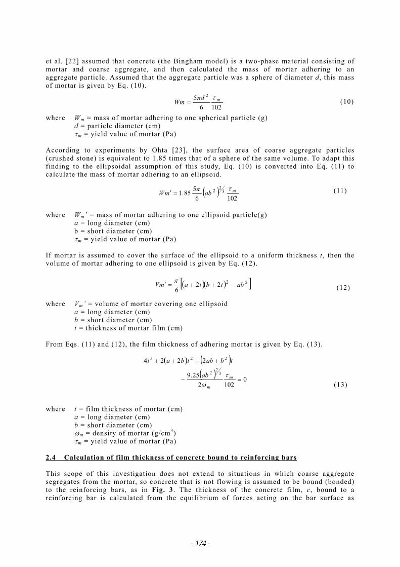
et al. [22] assumed that concrete (the Bingham model) is a two-phase material consisting of mortar and coarse aggregate, and then calculated the mass of mortar adhering to an aggregate particle. Assumed that the aggregate particle was a sphere of diameter d, this mass of mortar is given by Eq. (10).
(10)
where Wm = mass of mortar adhering to one spherical particle (g) d = particle diameter (cm) τm = yield value of mortar (Pa) According to experiments by Ohta [23], the surface area of coarse aggregate particles (crushed stone) is equivalent to 1.85 times that of a sphere of the same volume. To adapt this finding to the ellipsoidal assumption of this study, Eq. (10) is converted into Eq. (11) to calculate the mass of mortar adhering to an ellipsoid.
(11)
where Wm’ = mass of mortar adhering to one ellipsoid particle(g) a = long diameter (cm) b = short diameter (cm) τm = yield value of mortar (Pa) If mortar is assumed to cover the surface of the ellipsoid to a uniform thickness t, then the volume of mortar adhering to one ellipsoid is given by Eq. (12).
(12)
where Vm’ = volume of mortar covering one ellipsoid a = long diameter (cm) b = short diameter (cm) t = thickness of mortar film (cm) From Eqs. (11) and (12), the film thickness of adhering mortar is given by Eq. (13).
(13)
where t = film thickness of mortar (cm) a = long diameter (cm) b = short diameter (cm) ωm = density of mortar (g/cm3)
τm = yield value of mortar (Pa)
2.4 Calculation of film thickness of concrete bound to reinforcing bars This scope of this investigation does not extend to situations in which coarse aggregate segregates from the mortar, so concrete that is not flowing is assumed to be bound (bonded) to the reinforcing bars, as in Fig. 3. The thickness of the concrete film, c, bound to a reinforcing bar is calculated from the equilibrium of forces acting on the bar surface as
α2φτ
ω dh
dv cc =
∫ ==π2
0α
2φτ
ω cc
cc τhπφdh
V
−
+=
22
22φcφhπVc
−+= φ
ω
φφc c
c 102τ4
21 2
72 10129×=
Sf.
cτ
given below. Since the flow velocity of concrete is assumed to be 0 cm/s at the bar surface, Eq. (14) is derived from the equilibrium of vertical forces acting on an infinitesimal area of the reinforcing bar surface, φh/2 dα, as shown in Fig. 5.
(14)
where ωc = density of concrete (g/cm3)
dv = infinitesimal volume of concrete bound to an infinitesimal area
τc = yield value of concrete (g/cm2) φ = bar diameter (cm) h = bar length (cm)
By integrating Eq. (14) with respect to α, the mass of concrete bound to bar is obtained using Eq. (15).
(15)
where ωcVc = mass of concrete bound to reinforcing bar (g) If it is assumed that the thickness of concrete bound to a reinforcing bar is constant at c, the volume of concrete bound to a single bar is given by Eq. (16).
(16)
where Vc = volume of concrete bound to a single bar (cm3) c = thickness of concrete film (cm) By substituting Eq. (15) into Eq. (16), the concrete film thickness is given by Eq. (17).
(17)
where τc = yield value of concrete (Pa) According to Komura et al. [24], the yield value of concrete is given by Eq. (18) if the concrete density is taken to be ωc = 2.3 g/cm3.
(18)
where Sf = slump flow of concrete (mm) According to the JSCE Recommendations [7], more than 70% of self-compacting concrete is specified with a slump flow between 600 and 700 mm regardless of type. In this study, as
h
φ
αd α
2/φ
αdhc
2φτ
dvcω
h
φ
αd α
2/φ
αdhc
2φτ
dvcω
αdhc
2φτ
dvcω
Fig.5 Forces acting on infin itesimal area o f rebar surface
well, a slump flow of 600 mm is adopted; this simulates the more severe conditions for passage through the bars (small Le). The concrete film thickness was calculated from Eq. (17), while calculating τc from Eq. (18) and assuming ωc to be 2.3 g/cm3. 2.5 Modeling of bridging of coarse aggregate particles covered in mortar film As explained in Section 2.1 of this Chapter, the limit state of self-compactability is assumed to be a stable bridging structure consisting of circular particles with a diameter of d + 2t in contact with one another in the two-dimensional cross section of a space framed with bars. It is therefore necessary to model the bridging of circular particles. The bridging structure is assumed to be a packed structure of circular particles, and the method of developing such a structure is described in this Section. a) Bridging structure assumptions The packing structure is known to vary depending on particle size, and the model shown in Fig. 6 has been proposed to explain differences packing structures [25]. This figure indicates that a particle of diameter D larger than a critical particle diameter Dc yields a packing structure different from the case where D<Dc. For particles with D>Dc, as shown in Fig. 6 (a), the action of gravity on the particles exceeds the inter-particle forces, such as bonding force and cohesive force, causing the particles to drop down into the mechanically most stable position, where they become densely packed. On the other hand, small light particles with D<Dc, as shown in Fig. 6 (b), are held at the point of first contact by inter-particle forces, and the resulting packing structure has a high void percentage. The critical particle diameter, Dc, represents the diameter at which the force of gravity acting on a particle equals the inter-particle force, and is thought to range from 30 to 50 µm. Since the coarse aggregate particles dealt with in this study are no smaller than 5 mm, the packing structure shown in Fig. 6 (a) is adopted for simulation. b) Method of producing assumed packing structure To model the random phenomenon of spherical particle packing, a Monte-Carlo simulation was adopted. This is a technique generally used to reproduce such random behavior as the packing of spherical particles using random numbers [26]. Among studies based on the Monte-Carlo technique, Ito et al. [27] simulated the packing of spherical particles having a discontinuous size distribution. The authors adopt the packing behavior proposed in this investigation, which results in a packing structure similar to that shown in Fig. 6 (a), and formulate a 2-D circular particle packing program by extending it to include continuous size distributions. The procedure for achieving packing is as follows: Circular particles are generated in conformity with the specified size distribution using Weibull quasi-random numbers and then placed in random positions (using uniform quasi-random numbers) above the packing layer. The particles are then allowed to fall vertically based on the following three assumptions:
1) Circular particles fall individually. 2) Circular particles do not bounce when they collide. 3) Packed circular particles do not move when a collision occurs.
The falling particles are assumed to fall, until they come into contact with the packed particles, and then roll down to the most mechanically stable position, where they stop.
Fig.6 Particle packing models
D > Dc D < Dc(a) (b)
Fig.6 Particle packing models
D > Dc D < Dc(a) (b)
D > Dc D < Dc(a) (b)
( ) pe Ulogd1
θ−=′
Figures 7 and 8 show the assumed packing behavior of particles and a flow chart of packing structure generation, respectively. The programming language used for formulating the packing structure is Visual Basic 6.0 (Microsoft) [28],[29]. The Weibull quasi-random numbers are given by Eq. (19) [17].
(19)
where d’=particle diameter
generated by Weibull quasi-random numbers (mm)
U = uniform quasi-random numbers in range (0, 1)
p, θ = parameters in Eq. (3) 2.6 Method of calculating maximum coarse aggregate content Figure 9 shows the calculation flow used to obtain the maximum coarse aggregate content by the Monte-Carlo method. The thickness of the mortar film used in the packing simulation of circular particles is assumed to be, t50, corresponding to mean diameter d50 to simplify the calculation. The number of calculation trials for the packing simulation is 100 to improve the accuracy of the 95% confidence interval for Vglim.
B
A
B B
AA
(a) Particle A falls (b) Particle A comesinto contact withParticle B
(c) ) Particle A rolls ontoParticle B and settles
Fig.7 Packing behavior of part icles
B
A
B B
AA
(a) Particle A falls (b) Particle A comesinto contact withParticle B
(c) ) Particle A rolls ontoParticle B and settles
B
A
B B
AA
(a) Particle A falls (b) Particle A comesinto contact withParticle B
B
A
B B
AA
(a) Particle A falls (b) Particle A comesinto contact withParticle B
(c) ) Particle A rolls ontoParticle B and settles
Fig.7 Packing behavior of part icles
Place part icle at top of packing range according to uniform quasi-random
numbers
Allow particle to fall vertically
Judge contact of the particle
Roll part icle on the packed particle until it comes into contact with another surface(of packed particle, bar, or the bottom)
Is settled particle in the packing range?
Change the drop position according to uniform quasi-random numbers
Number of changes to drop position > 500
END
Place part icle on the bottom
Set Weibull quasi-random numbers fordiameters of circu lar particles to be packed
START
Set packing range
Settled?
Settled?
Contact with bottom
Contact with a packed particleYes
No
Yes
No
No
Yes
Yes
No
Generate circular part icle according to Weibull quasi-random numbers (including diameter
conversion in consideration of t50)
Set thickness of adhering mortar film, t50
Place part icle at top of packing range according to uniform quasi-random
numbers
Allow particle to fall vertically
Judge contact of the particle
Roll part icle on the packed particle until it comes into contact with another surface(of packed particle, bar, or the bottom)
Is settled particle in the packing range?
Change the drop position according to uniform quasi-random numbers
Number of changes to drop position > 500
END
Place part icle on the bottom
Set Weibull quasi-random numbers fordiameters of circu lar particles to be packed
START
Set packing range
Settled?Settled?
Settled?Settled?
Contact with bottom
Contact with a packed particleYes
No
Yes
No
No
Yes
Yes
No
Generate circular part icle according to Weibull quasi-random numbers (including diameter
conversion in consideration of t50)
Set thickness of adhering mortar film, t50
Fig.8 Procedure fo r fo rming packing structure
3. VERIFICATION OF SPACE BLOCKING MODEL The validity of the space blocking model is verified using test data taken from the literature. The input values for analysis with the model are as given in Table 1. Excepting the equalized concrete properties for setting the concrete film thickness, c, the input values match the original test conditions. Vglim is determined by following the calculation flow shown in Fig. 9. 3.1 Influence of coarse aggregate particle size distribution Figures 10 and 11 show test results previously reported by the authors [10], presented here to demonstrate that different particle size distributions can lead to different Vglim values yet achieve self-compactability. The maximum fill height in the U-type tester is set by changing the volumetric water-powder ratio, Vw/Vp, while keeping other proportions unchanged (Table 2), for each unit absolute volume of coarse aggregate, Vg. It should be noted that Vglim is assumed to be the coarse aggregate content corresponding to a maximum fill height according to the U-type tester, Bhmax, of 30 cm. Figures 12 and 13 show the grading and solid volume percentage, respectively, of the coarse aggregate used for the tests.
Measure coarse aggregate grading
Identify parameters p and of Eq. (3)
Obstacle conditions of U-type testerL0:Mean net opening between barsφ:Bar diameterh: Bar length (height of opening cross section)
Measure aspect ratio of coarse aggregate particles
1=i
100>i
1+= ii
iii mPF δε1 −−=
( )
−−=
250
22
4δ tDD
hLeπnm i
∑=
−=n
kki /D
hLe 1
2 4π11ε
∑=
=n
kkD
nD
1
15025 tdD kk ++′=
Generate particle d iameter, dk’ according to Eq. (19) and pack circu lar particles with diameters converted to Dk in the cross section (Le × h). The number of circu lar particles after completion of packing is n
Simulate packing of circular part icles
pfb/a.
b/aPFlimVg σ961
±=
∑=
=100
11001
iiPFPF
Calcu late maximum coarse aggregate content, Vglim
Set the yield value and density of mortar
Calcu late mean aspect ratio b/a
Set the packing range (space cross section) (width = Le, height = h)
cLLe 20 −=
Calcu late the thickness of themortar film from Fig. (13)
Long diameter, a = mean d iameter, d50
=μ+5 (μ: Eq.(5))50t
Yes
No
Calcu late the concrete film thickness, c by Eq. (17)
( )∑=
−=100
1
2
1001
iipf PFPFσ
Measure coarse aggregate grading
Identify parameters p and of Eq. (3)
Obstacle conditions of U-type testerL0:Mean net opening between barsφ:Bar diameterh: Bar length (height of opening cross section)
Measure aspect ratio of coarse aggregate particles
1=i
100>i
1+= ii 1+= ii
iii mPF δε1 −−=
( )
−−=
250
22
4δ tDD
hLeπnm i
∑=
−=n
kki /D
hLe 1
2 4π11ε
∑=
=n
kkD
nD
1
15025 tdD kk ++′=
Generate particle d iameter, dk’ according to Eq. (19) and pack circu lar particles with diameters converted to Dk in the cross section (Le × h). The number of circu lar particles after completion of packing is n
Simulate packing of circular part icles
pfb/a.
b/aPFlimVg σ961
±=
∑=
=100
11001
iiPFPF
Calcu late maximum coarse aggregate content, Vglim
Set the yield value and density of mortar
Calcu late mean aspect ratio b/a
Set the packing range (space cross section) (width = Le, height = h)
cLLe 20 −=
Calcu late the thickness of themortar film from Fig. (13)
Long diameter, a = mean d iameter, d50
=μ+5 (μ: Eq.(5))50t
Yes
No
Calcu late the concrete film thickness, c by Eq. (17)
( )∑=
−=100
1
2
1001
iipf PFPFσ
Fig.9 Calculation procedure for maximum coarse aggregate content
Input values for analysisSec.(1): Determine from measureddistribution
Sec.(2): Estimate from fineness modulus ofcoarse aggregate
Film thickness of adheringmortar
Substitute the following values into Eq. (13)
Sec.(1): Estimate from measured mortar flow
Sec.(2): Input measured yield value of mortar
Density of mortar Sec.(1), (2): Determine from mix proportions
Mean diameter of coarseaggregate (in number-based size distribution)
Sec.(1), (2): μ+ 5(mm); μ is determinedfrom Eq. (5)
Sec.(1): Input measured aspect ratioSec.(2): Estimate from solid volumepercentage
Effective width of opening Calculate by assuming Le =L0 - 2cMean net opening betweenreinforcing bars
Sec.(1), (2): Input bar obstacle conditions
Thickness of concrete filmbound to reinforcing bars
Sec.(1), (2): Determine from φ by Eq. (17)assuming Sf = 600mm, ωc = 2.3 g/cm3
φ bar diameter Sec.(1), (2): Input bar obstacle conditionsSpace height Sec.(1), (2): Input bar obstacle conditions
c
L 0
h
ω m
d 50
Le
τ m Yield value of mortar
a/b Mean aspect ratio ofcoarse aggregate
t 50
Method of determination
Constants for probabilitydensity functions followingthe number-based sizedistribution of coarseaggregate
θ , p
SymbolInput values for analysis
Table 1 Input values for analysis and their determination
Vf/Vp(%vol)
Vs/Vm(%vol)
Wsp/Wp(%wt)
Va(%)
50 45 1.5 6±1
Vf/Vg: Replacement ratio by volume of fly ash toVs/Vm: Ratio by volume of fine aggregate to morWsp/Wp: Ratio by weight of superplasticizer to pVa: Air content
Table 2 Proportioning conditions
0
50
100
150
200
250
300
350
400
0.32 0.34 0.36 0.38 0.40 0.42 0.44
Unit absolute volume of coarse aggregate, Vg (m3/m3)
Fine
Coarse
Obstacle condition: R2
Max
imum
fill
heig
ht w
ith U
-type
test
er, B
hmax
(mm
)
Vglim offine grain
Vglimof coarse
grain
Fig. 10 Relationship between unit absolute volume of coarse aggregate and maximum fill height (R1)
0
50
100
150
200
250
300
350
400
0.26 0.28 0.30 0.32 0.34 0.36 0.38
Unit absolute volume of coarse aggregate, Vg (m3/m3)Max
imum
fill
heig
ht w
ith U
-type
test
er, B
hmax
(mm
)
Fine grain
粗粒
Obstaclecondition: R1
A B
C
D E
F
GVglim ofcoarsegrain
Vglim offine grain
Coarse
Fig.11 Unit absolute volume of coarse aggregate (R2)
0
10
20
30
40
50
60
70
80
90
100
0 5 10 15 20 25 30
Nominal size of sieve opening (mm)
Perc
enta
ge p
assin
g by
weig
ht (%
)
Range of standardgrading by JIS A5005
Coarse grain
Fine grain
Fig. 12 Grading of coarse aggregate
55
56
57
58
59
60
6.2 6.4 6.6 6.8 7.0 7.2
Fineness modulus of coarse aggregate, FM
Solid
vol
ume
perc
enta
ge o
f coa
rse
aggr
egat
e, G
lim (
%)
Fine grain
Range of FMcorresponding to standard
grading by JIS A 5005
Coarsei
Fig. 13 Solid volume percentage of coarse aggregate
0
50
100
150
200
250
300
350
400
0.26 0.28 0.30 0.32 0.34 0.36 0.38
Unit absolute volume of coarse aggregate, Vg (m3/m3)Max
imum
fill
heig
ht w
ith U
-type
test
er, B
hmax
(mm
)
Fine grain
粗粒
Obstaclecondition: R1
A B
C
D E
F
GVglim ofcoarsegrain
Vglim offine grain
Coarse
0
50
100
150
200
250
300
350
400
0.32 0.34 0.36 0.38 0.40 0.42 0.44
Unit absolute volume of coarse aggregate, Vg (m3/m3)
Fine
Coarse
Obstacle condition: R2
Max
imum
fill
heig
ht w
ith U
-type
test
er, B
hmax
(mm
)
Vglim offine grain
Vglimof coarse
grain
J
K
M
N
L
H I
Input values for analysisSec.(1): Determine from measureddistribution
Sec.(2): Estimate from fineness modulus ofcoarse aggregate
Film thickness of adheringmortar
Substitute the following values into Eq. (13)
Sec.(1): Estimate from measured mortar flow
Sec.(2): Input measured yield value of mortar
Density of mortar Sec.(1), (2): Determine from mix proportions
Mean diameter of coarseaggregate (in number-based size distribution)
Sec.(1), (2): μ+ 5(mm); μ is determinedfrom Eq. (5)
Sec.(1): Input measured aspect ratioSec.(2): Estimate from solid volumepercentage
Effective width of opening Calculate by assuming Le =L0 - 2cMean net opening betweenreinforcing bars
Sec.(1), (2): Input bar obstacle conditions
Thickness of concrete filmbound to reinforcing bars
Sec.(1), (2): Determine from φ by Eq. (17)assuming Sf = 600mm, ωc = 2.3 g/cm3
φ bar diameter Sec.(1), (2): Input bar obstacle conditionsSpace height Sec.(1), (2): Input bar obstacle conditions
t 50
Method of determination
Constants for probabilitydensity functions followingthe number-based sizedistribution of coarseaggregate
θ , p
SymbolInput values for analysis
τ m Yield value of mortar
a/b Mean aspect ratio ofcoarse aggregate
c
L 0
h
ω m
d 50
Le
55
56
57
58
59
60
6.2 6.4 6.6 6.8 7.0 7.2
Fineness modulus of coarse aggregate, FM
Solid
vol
ume
perc
enta
ge o
f coa
rse
aggr
egat
e, G
lim (
%)
Fine grain
Range of FMcorresponding to standard
grading by JIS A 5005
Coarse grain
Comparisons between measured values of Vglim and those estimated using the space blocking model are discussed in the following sections. a) Parameter setting for space blocking model (i) Particle size distribution The particle size distribution of the coarse aggregate used in the analysis, as shown in Fig. 12, is converted into a number-based density function described in Chapter 2, Section (2). The result is shown in Fig. 14. (ii) Mean aspect ratio The aspect ratio of the coarse aggregate was measured using a digital camera as an image input device and a personal computer with commercially available software as an image analysis system. The aggregate particles were divided into two groups by size: 5-10 mm and 10-25 mm. Each group was photographed, and the long and short diameters of the images were measured on the PC using Power Point 97 (Microsoft). The aspect ratio was then calculated using Eq. (9). The number of randomly selected particle samples was 100 for each group. In previous experiments [10], fine-grain and coarse-grain concretes were mixed by including coarse aggregate particles at mass ratios of 55:45 and 20:80, respectively, from the 5-10 mm and 10-25 mm groups. The mean aspect ratios are calculated similarly here. In other words, the measured aspect ratio for each size group is applied to the probability density function of Eq. (3) for the Weibull distribution to quantify it. Figure 15 shows the measured data and the probability density function to which the measured data are applied. It should be noted that goodness-of-fit testing is carried out for each size group, and that goodness of fit is confirmed at a significance level of 5%. The mean aspect ratio used for the analysis is determined by generating random numbers conforming to the probability density function for each size group and taking samples from the aspect ratio distribution for each size group according to the number fraction to obtain 500 samples in total. The mean value is taken as the aspect ratio. It should be noted that all generated random numbers are proven to satisfy the 5% level of significance (frequency checking and serial correlation checking) [31],[32].
0.00
0.05
0.10
0.15
0.20
0.25
0 5 10 15 20
Particle diameter, d ' (mm)
Num
ber-
base
d pr
obab
ility
dens
ity, f
(d') Fine grain
(θ=3.57, p=1.63)
Coarse grain(θ=5.36, p=1.57)
Fig. 14 Probability density function of grading
0.0
0.5
1.0
1.5
2.0
2.5
0 1 2 3
a/b-1
Num
ber-
base
d pr
obab
ility
dens
ity
f(x) Measurements(5-10mm)
Measurements(10-25mm)
Probability density function(5-10mm)Probability density function(10‐25mm)
5-10mm(θ=0.429, p=1.27)
10-25mm(θ=0.425, p=1.70)
Fig. 15 Measured aspect ratios and probability density functions
(iii) Mortar properties The density and yield value of the mortar have to be established in order to quantify mortar properties. Figures 16 and 17 show the influence of unit absolute volume of coarse aggregate, Vg, on concrete slump flow and mortar flow (mortar wet-screened with a 5-mm sieve) shown in Figs. 10 and 11, respectively. The data in the figures represent the maximum values of slump flow and mortar flow obtained without segregation occurring. These figures demonstrate that a finer aggregate leads to a higher concrete slump flow than a coarse aggregate with the same Vg, regardless of obstacle conditions. The effect of aggregate on mortar flow is similar. Accordingly, finer grading of the coarse aggregate particles can lead to increased fluidity and improved self-compactability while avoiding segregation, eventually allowing for a higher maximum coarse aggregate content. Since differences in mortar properties are assumed to result from variations in the particle size distribution, it is necessary to establish mortar properties for each size distribution. Another series of experiments is conducted to determine the relationship between flow and yield value of wet-screened mortar, as yield values were not covered by the previous experiments [10]. Tables 3 and 4 give the mix proportions of the concrete and the materials used, respectively.
500
550
600
650
700
750
0.25 0.3 0.35 0.4 0.45
Unit absolute volume of coarse aggregate, Vg (m3/m3)
Slu
mp
flow
of
mix
es
atta
inin
g B
hm
ax ,
Sf(m
m)
Fine grain(R1)Coarse grain(R1)
Fine grain(R2)Coarse grain(R2)
Fig. 16 Relationship between unit absolute volume of coarse aggregate and slump flow of concrete
200
250
300
350
400
0.25 0.3 0.35 0.4 0.45
Unit absolute volume of coarse aggregate, Vg (m3/m3)
Mor
tar f
low
of m
ixes
atta
inin
g B
hm
ax,
Fm(m
m)
Fine grain(R1)Coarse grain(R1)Fine grain(R2)Coarse grain(R2)
Fig. 17 Relationship between unit absolute volume of coarse aggregate and mortar flow
Water-powderratio
Ww/Wp(%wt)
Sand-mortarratio
Vs/Vm(%vol)
Unit absolutevolume of
coarseaggregate
Vg (m3/m3)
Dosage ofSuper-
plasticizerWsp/Wp(%wt)
AircontentVa (%)
0.250.280.30
32.4 0.35~0.55 1.5~1.9 6±1
Table 3 Cases of mix proportion
Material SpecificationsNormal portlandcement
Density: 3.16g/cm3, Specific surfacearea by blaine: 3,360cm2/g
Fly ash made fromimported coal
PR/BA coal (ignition loss: 1.8%,methylene blue adsorption: 0.64mg/g,density: 2.13g/cm3, specific surface byBlaine: 2,790cm2/g, bulk density:1.221g/cm3, packing ratio: 57.3%)Land sand from Hamaatsuma (SSDdensity: 2.70g/cm3, absorption: 2.13%,FM: 2.48, solid volume percentage:65.5%)Crushed stone 2005 from Teine (SSDdensity: 2.68g/cm3, absorption: 1.44%,FM: 6.84, solid volume percentage:59.3%)
Superplasticizer Complex of polycarboxylic ether typeand crosslinking polymer
The mixing method is the same as in the previous experiments [10]. Figure 18 shows the mortar flow versus yield value relationship, and the results of regression of this relationship are expressed as Eq. (20). Yield values are obtained using a rotational viscometer (HAAKE RS150 with vane sensors) under stress control (minimum stress = 0.05 Pa).
(20)
where τm = yield value of mortar (Pa) Fm = mortar flow (mm) Table 5 gives the estimated density and yield value of the mortar in the concrete of Figs. 10 and 11, as determined from the above results. For the analysis, the mean property values of two mortar mixtures, one below and one above Vglim were selected for each of the obstacle conditions and grain types. (indicated by the hatched cells in Table 5), (iv) Selection of concrete film thickness The film thickness of concrete bound to reinforcing bars was calculated using Eq. (17) as follows:
Obstacle conditions R1 (Lo = 35 mm, φ (bar diameter) = 10 mm): c = 6.5 mm Obstacle conditions R2 (Lo = 40 mm, φ = 13 mm): c = 7.0 mm
b) Comparison of space blocking model and measurements Figures 19 and 20 compare measurements of Vglim with values estimated by the space blocking model. The analytical parameters are given in Table 6. Fine-grain mixtures yield higher Vglim values than coarse-grain mixtures, and Vglim decreases as the mean net opening decreases for both obstacle conditions. Absolute values of measured and estimated Vglim are also similar. The analytical values tend to indicate that the influence of grading on Vglim falls as the mean net opening increases, which is similar to the phenomenon reported by Matsuo and Ozawa [9]. Further, the experiment values fall
Fig. 18 Relationship between mortar flow and yield value
within the 95% confidence interval of the analytical values, suggesting that use of the space blocking model to estimate Vglim, as proposed in this paper, is applicable to any grading. 3.2 Influence of obstacle conditions The influence of coarse aggregate particle size distribution under the obstacle conditions specified by the JSCE test method [7] was investigated in the previous section. However, the variations in bar spacing and bar diameter specified in this test method are not as great as those found in actual structures. Sakamoto et al. [33],[34] conducted experiments on the effects of obstacle conditions and coarse aggregate content on the self-compactability of combination-type self-compacting concrete using three widely different bar spacings. Their results are illustrated in Fig. 21. The applicability of the space blocking model to any given obstacle conditions is investigated in the following sections based on this experimental data reported by Sakamoto et al. a) Parameter setting for space blocking model (i) Particle size distribution Since no grading data are given in the Sakamoto report, an assumed particle size distribution was adopted for the coarse aggregate (Gmax = 20 mm), as shown in Fig. 22. This was estimated from the measurements of fineness modulus (6.70) by adopting a particle size distribution corresponding to the fineness modulus assumed in the range of standard grading specified in JIS A 5005. Values of θ = 4.19 and p = 1.35 were selected as the parameters in
Analysis parametersCoarse aggregate quality Mortar properties Thickness of
adheringmortar filmt 50 (mm)
Bar obstacle condition Concretefilm
thicknessc (mm)
R1 35 10 6.5
R2 40 13 7.0
Table 6 Analysis parameters
200
35 35 35
D19
53 53
D16
Type: US1 Type: US2
83 83
190
Type: US3
35 59
D16 D16/2[in mm]
200
35 35 35
D19
53 53
D16
Type: US1 Type: US2
83 83
190
Type: US3
35 59
D16 D16/2[in mm]
Fig.21 Bar obstacle conditions in U-type tester
Eq. (3) for this particle size distribution. The mean diameter of the coarse aggregate according to the number-based distribution is 8.8 mm. (ii) Mean aspect ratio Figure 23 shows the relationship between solid volume percentage and mean aspect ratio based on data presented by Iwai et al. (given as the “square ratio” in the original text) [35] as well as on data by the authors (average of fine-grain and coarse-grain types). Given the good correlation between the solid volume percentage and aspect ratio of crushed stone, the mean aspect ratio is estimated from the solid volume percentage using Eq. (21) (Solid volume percentage = 60.3%, mean aspect ratio = 1.40).
(21) where ba = mean aspect ratio of coarse aggregate Glim = solid volume percentage of coarse aggregate (%) (iii) Mortar properties Sakamoto et al. measured the yield value of mortar wet-screened from concrete. Since the yield value of the mortar for each set of obstacle conditions is not specifically reported, the average of all mixtures (C4-C7 in the original text) is adopted. The mortar yield value and density are therefore assumed to be 15 Pa and 2.10 g/cm3, respectively. These values are substituted into Eq. (13) to calculate the film thickness of mortar adhering to the bars, t50 (= 0.8 mm). (iv) Film thickness of concrete The thickness of the concrete film bound to the reinforcing bars is calculated using Eq. (17) as follows:
Obstacle condition US1 (Lo = 35 mm, bar diameter (φ) = 19 mm): c = 7.7 mm Obstacle condition US2 (Lo = 55 mm, φ = 16 mm): c = 7.4 mm Obstacle condition US3 (Lo = 83 mm, φ = 16 mm): c = 7.4 mm
82304010 .limG.b/a +−=
R2 = 0.765
1.30
1.35
1.40
1.45
1.50
1.55
1.60
56 58 60 62 64 66 68
Solid volume percentage of coarse aggregate, Glim(%)
Mea
n as
pect
ratio
of c
oars
e ag
greg
ate,
a
/b
Crushed stoneRiver gravel
B
E
C
D A
River gravel
Place of productionA: OhmeB: IwaseC: TsukubaD: KasamaE: TeineRiver gravel: Kinugawa
Fig. 23 Relationship between solid volume percentage and mean aspect ratio of coarse aggregate
b) Comparison of space blocking model and measurements Figure 24 compares the coarse aggregate content that results in a fill height of 30cm in a U-type tester (maximum coarse aggregate content) with estimates obtained using the space blocking model. The measurements for all obstacle conditions fall mostly within the 95% confidence interval of the analytical values, suggesting that the space blocking model proposed by the authors is applicable to the estimation of Vglim under any given bar conditions. The self-compacting concrete used in the Sakamoto experiments was not a powder type as used by the authors but a combination type. The proposed method is applicable to these differing types of self-compacting concrete because mortar properties are treated as physical quantities in the model. In consideration of a safety factor, self-compacting concrete can be proportioned by adopting the lower limit of the 95% confidence interval of Vglim (allowable maximum coarse aggregate content, Vglim’) estimated using the space blocking model. 4. INFLUENCE OF VARIOUS FACTORS ON Vglim The validity of the space blocking model was verified in the previous chapter, and its applicability was confirmed. In this chapter, assessment of the influence of various factors on Vglim is carried out using the space blocking model. The concrete slump flow, grading (fineness modulus), and solid volume percentage of coarse aggregate as well as the obstacle conditions were selected as factors affecting Vglim based on the results already described. The method of assessing the degrees of influence of each factor is as described below. Three different gradings are adopted, as shown in Fig. 25. The mean aspect ratio is determined from Eq. (21) in regard to the range of solid volume percentage between 57% and 62%. As obstacle conditions, the net opening between bars is 35 mm to 200 mm and the bar diameter is D10 to D19 so as to simulate standard self-compacting concrete placed in situ. It is necessary to establish mortar properties for the analysis such that the slump flow
0.30
0.32
0.34
0.36
0.38
0.40
20 40 60 80 100Mean net opening between bars, L 0 (mm)
Max
imum
coa
rse
aggr
egat
e co
nten
t,Vg
lim(m
3 /m3 )
MesuredAnalyzed (US1)
Analyzed (US2,US3)
95% confidenceinterval of
US2,US3(D16)
95% confidenceinterval of US1
(D19)
Vglim' of US2,US3
Vglim' of US1
Fig. 24 Comparison between measured and analyzed values in the literature
0
10
20
30
40
50
60
70
80
90
100
0 5 10 15 20 25 30 35 40
Nominal size of sieve opening (mm)
Perc
enta
ge p
assi
ng b
y w
eigh
t (%
)
Range ofstandard gradingby JIS A 5005
FM=7.1Gmax=25
FM=6.7Gmax=20
FM=6.1Gmax=10
Fig. 25 Grading of coarse aggregate used in analysis
falls within the self-compacting range. The yield value of the mortar is therefore determined by using the relationship between mortar flow and slump flow (Eq. (22)) established from previous test results [10], as shown in Fig. 26, and substituting the result into Eq. (20). The average density of all mixtures in Fig. 26, that is 2.08 g/cm3, is adopted as the density. However, the mortar yield value is established so as to correspond to a slump flow within the range Sf = 600-650 mm, since concrete tends to segregate when the slump flow exceeds 650 mm in Fig. 26.
(22)
where Fm = mortar flow of wet-screened
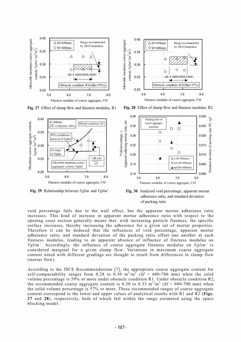
mortar (mm) Sf = slump flow of concrete (mm) 4.1 Influence of slump flow and fineness modulus The analysis cases described in Table 7 are compared to assess the influence of concrete slump flow and coarse aggregate grading (fineness modulus) on Vglim. The analysis result for each obstacle condition is shown in Figs. 27 and 28. The allowable maximum coarse aggregate content, Vglim’, refers in the figure to the maximum coarse aggregate content at which self-compactability is maintained (that is, the lower limit of the 95% confidence interval of Vglim). These figures reveal that Vglim’ strongly depends on the slump flow but is scarcely affected by the fineness modulus. Accordingly, when proportioning for a target slump flow of, e.q., 650 mm, it is recommended that a Vglim’ value corresponding to a 600 mm slump flow (that is, a 50 mm reduction) be selected to be on the safe side, as a 600 mm slump flow is regarded as being within the quality tolerances. An investigation is carried out to assess the influence of fineness modulus in detail. Figure 29 shows the relationships between Vglim and Vglim’ used in calculating the values in Fig. 27. This figure reveals that Vglim’ has the same value regardless of variations in fineness modulus, whereas the average and confidence interval of Vglim decrease as the fineness modulus of the coarse aggregate decreases. The relationships among void percentage, apparent mortar adherence ratio, and standard deviation of packing ratio corresponding to the fineness modulus used in calculating the values in Fig. 29 are shown in Fig. 30. This figure reveals that, as the fineness increases, the
Fig. 26 Relationship between slump flow and mortar flow
Fig. 27 Effect of slump flow and fineness modulus, R1
0.20
0.25
0.30
0.35
0.40
5.0 6.0 7.0 8.0
Fineness modulus of coarse aggregate, FM
Allo
wab
le m
axim
um c
oars
e ag
greg
ate
cont
ent,
Vglim
' (m
3 /m3 )
Sf=650mmSf=600mm
JIS A 5005(2005,2505)
Range recommendedby JSCE Guidelines
void percentage falls due to the wall effect, but the apparent mortar adherence ratio increases. This kind of increase in apparent mortar adherence ratio with respect to the opening cross section generally means that, with increasing particle fineness, the specific surface increases, thereby increasing the adherence for a given set of mortar properties. Therefore it can be deduced that the influences of void percentage, apparent mortar adherence ratio, and standard deviation of the packing ratio offset one another at each fineness modulus, leading to an apparent absence of influence of fineness modulus on Vglim’. Accordingly, the influence of coarse aggregate fineness modulus on Vglim’ is considered marginal for a given slump flow. Variations in maximum coarse aggregate content noted with different gradings are thought to result from differences in slump flow (mortar flow). According to the JSCE Recommendations [7], the appropriate coarse aggregate content for self-compactability ranges from 0.28 to 0.30 m3/m3 (Sf = 600-700 mm) when the solid volume percentage is 59% or more under obstacle condition R1. Under obstacle condition R2, the recommended coarse aggregate content is 0.30 to 0.33 m3/m3 (Sf = 600-700 mm) when the solid volume percentage is 57% or more. These recommended ranges of coarse aggregate content correspond to the lower and upper values of analytical results with R1 and R2 (Figs. 27 and 28), respectively, both of which fall within the range estimated using the space blocking model.
0.20
0.25
0.30
0.35
0.40
5.0 6.0 7.0 8.0
Fineness modulus of coarse aggregate, FM
Max
imum
coa
rse
aggr
egat
e co
nten
t,Vg
lim (
m3 /
m3)
Sf=600mma/b =1.45(Glim=59%)
1.96σpf
a/b
95% confidenceinterval of Vglim
Averageof Vglim
Allowable maximumcoarse aggregate content,V li '
Obtacle conditions:R1
Fig. 29 Relationship between Vglim and Vglim'
0.10
0.15
0.20
0.25
0.30
0.35
0.40
5.0 6.0 7.0 8.0
Fineness modulus of coarse aggregate, FM
0.000
0.005
0.010
0.015
0.020
0.025
0.030
Stan
dard
dev
iatio
n of
pac
king
ratio
PF,
σpf
ε(Sf=600mm)
δm(Sf=600mm)
σpf(Sf=600mm)
Voi
d pe
rcen
tage
, εA
ppar
ent a
dher
ing
mor
tar r
atio
, δm
Packing ratio ofcoarse aggregate
particles
Fig. 30 Analyzed void percentage, apparent mortar adherence ratio, and standard deviation of packing ratio
Fig. 28 Effect of slump flow and fineness modulus, R2
0.20
0.25
0.30
0.35
0.40
5.0 6.0 7.0 8.0
Fineness modulus of coarse aggregate, FM
Allo
wab
le m
axim
um c
oars
e ag
greg
ate
cont
ent,
Vglim
' (m
3 /m3 )
Sf=650mmSf=600mm
JIS A 5005(2005,2505)
Range recommendedby JSCE Guidelines
0.20
0.25
0.30
0.35
0.40
5.0 6.0 7.0 8.0
Fineness modulus of coarse aggregate, FM
Allo
wab
le m
axim
um c
oars
e ag
greg
ate
cont
ent,
Vglim
' (m
3 /m3 )
Sf=650mmSf=600mm
JIS A 5005(2005,2505)
Range recommendedby JSCE Guidelines
Obstacle condition: R1(Glim=59%)0.20
0.25
0.30
0.35
0.40
5.0 6.0 7.0 8.0
Fineness modulus of coarse aggregate, FM
Allo
wab
le m
axim
um c
oars
e ag
greg
ate
cont
ent,
Vglim
' (m
3 /m3 )
Sf=650mmSf=600mm
JIS A 5005(2005,2505)
Range recommendedby JSCE Guidelines
Obstacle condition: R2(Glim=57%)
0.20
0.25
0.30
0.35
0.40
5.0 6.0 7.0 8.0
Fineness modulus of coarse aggregate, FM
Max
imum
coa
rse
aggr
egat
e co
nten
t,Vg
lim (
m3 /
m3)
Sf=600mma/b =1.45(Glim=59%)
1.96σpf
a/b
95% confidenceinterval of Vglim
Averageof Vglim
Allowable maximum coarseaggregate content, Vglim'
Obtacle conditions: R1
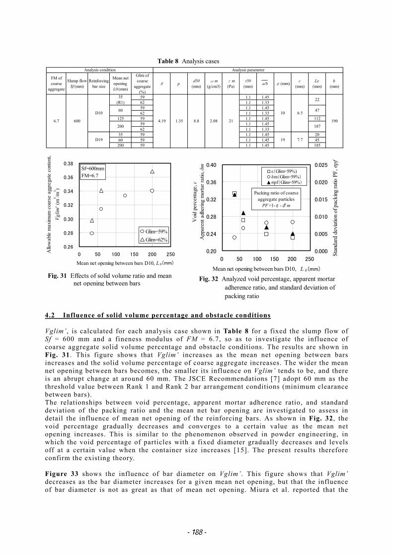
4.2 Influence of solid volume percentage and obstacle conditions Vglim’, is calculated for each analysis case shown in Table 8 for a fixed the slump flow of Sf = 600 mm and a fineness modulus of FM = 6.7, so as to investigate the influence of coarse aggregate solid volume percentage and obstacle conditions. The results are shown in Fig. 31. This figure shows that Vglim’ increases as the mean net opening between bars increases and the solid volume percentage of coarse aggregate increases. The wider the mean net opening between bars becomes, the smaller its influence on Vglim’ tends to be, and there is an abrupt change at around 60 mm. The JSCE Recommendations [7] adopt 60 mm as the threshold value between Rank 1 and Rank 2 bar arrangement conditions (minimum clearance between bars). The relationships between void percentage, apparent mortar adherence ratio, and standard deviation of the packing ratio and the mean net bar opening are investigated to assess in detail the influence of mean net opening of the reinforcing bars. As shown in Fig. 32, the void percentage gradually decreases and converges to a certain value as the mean net opening increases. This is similar to the phenomenon observed in powder engineering, in which the void percentage of particles with a fixed diameter gradually decreases and levels off at a certain value when the container size increases [15]. The present results therefore confirm the existing theory. Figure 33 shows the influence of bar diameter on Vglim’. This figure shows that Vglim’ decreases as the bar diameter increases for a given mean net opening, but that the influence of bar diameter is not as great as that of mean net opening. Miura et al. reported that the
Fig. 31 Effects of solid volume ratio and mean net opening between bars
0.20
0.24
0.28
0.32
0.36
0.40
0 50 100 150 200 250
Mean net opening between bars D10, L 0 (mm)
0.000
0.005
0.010
0.015
0.020
0.025
Stan
dard
dev
iatio
n of
pac
king
ratio
PF,
σpf
ε(Glim=59%)δm(Glim=59%)σpf(Glim=59%)
Voi
d pe
rcen
tage
, εA
ppar
ent a
dher
ing
mor
tar r
atio
, δm
Packing ratio of coarseaggregate particles
PF =1-ε-δ m
Fig. 32 Analyzed void percentage, apparent mortar adherence ratio, and standard deviation of packing ratio
ability of concrete to pass through a narrow opening decreases as the diameter of the bars increases even as the mean net opening remains the same [36]. The space blocking model appears to reflect this phenomenon properly. These results demonstrate that mortar properties (slump flow), mean net opening between bars, and solid volume percentage are predominant factors affecting Vglim’. Further, the coarse aggregate content in the JSCE Recommendations [7] is specified on the basis of a great deal of construction experience and experimental data, with slump flow, bar obstacle conditions, and solid volume percentage taken as the key factors, and this also confirms the validity of the estimation model for Vglim proposed here. The threshold between bar arrangement conditions for self-compactability Rank 1 and Rank 2 agrees with the estimation given by this model, and this also proves the validity of the proposed model. 5. CONCLUSIONS The limit state of self-compactability was assumed to be when bridging of coarse aggregate particles covered with a mortar film occurs. A space blocking model was then formulated by applying a probability model based on a Monte-Carlo simulation to the particle size distribution of coarse aggregate and the bridge structure. The validity of the model was assessed by comparison with studies in the literature, and this verified the proposed model. The model was also proven valid by comparison with the JSCE Recommendations. It is therefore concluded that the maximum coarse aggregate content, Vglim, can be estimated from the coarse aggregate quality (grading and mean aspect ratio) and mortar properties (yield value and density) by using the model under any given obstruct conditions caused by the bar arrangement in a U-type self-compactability tester. The mean aspect ratio and yield value of the mortar phase of the concrete require future investigation in order to improve the accuracy of the model and simplify the calculations. The authors also intend to investigate the relationship between mean aspect ratio and solid volume percentage, as well as the relationship between mortar phase yield value and the flow of mortar mixed without coarse aggregate. Since this study has made clear which mortar properties affect the limit state of self-compactability, the mortar proportioning factors that lead to such properties will also be investigated in relation to self-compactability. These will include the water-powder ratio, powder qualities, chemical admixture dosage, fine aggregate quality, and fine aggregate content. References [1] K.Takada, J.C.Walraven and W.Bennenk: Self-Compacting Concrete in the Netherlands,
Concrete Journal, JCI, Vol.38, No.3, pp.17-23, 2000. [2] I.Izumi: High Fluidity Concrete, Concrete Journal, JCI, Vol.36, No.11, pp.41-43, 1998. [3] T.Nawa, H.Eguchi, M.Okubo and Y.Fukaya: A Discussion on Mix Design and Fluidity of
Self-compacting Concrete, Proceedings of JCI, Vol.14, No.1, pp.369-374, 1992. [4] A.Dozono, H.Fujiwara and Y.Shimoyama: A Study on Passability of Self-compacting
Concrete between Reinforcing Bars, Proceedings of JSCE Annual Conference, Vol.Ⅴ, pp.308-309, 1994.
0.26
0.28
0.30
0.32
0.34
0.36
0.38
0 50 100 150 200 250
Mean net opening between bars, L 0 (mm)
Allo
wab
le m
axim
um c
oars
e ag
greg
ate
cont
ent,
Vglim
' (m
3/m
3)
D10D19
Sf=600mmFM=6.7Glim=59%
Fig. 33 Effect of bar diameter and mean net opening
[5] H.Okamura and K.Ozawa: Mix Design Method for Self-Compactable Concrete, Journal of Materials,Concrete Structures and Pavements, JSCE, No.496/V-24, pp.1-8, 1994.
[6] Recommendations for Mix Design and Construction Practice of Highly Fluid Concrete, Architectural Institute of Japan, 1997.
[7] Recommendations for Construction of Self-compacting Concrete Structures, Concrete Library 93, JSCE, 1998.
[8] Committee Report – Super Flowing Concrete (I), JCI, pp.12-18, 1993. [9] S.Matsuo and K.Ozawa: Effect of Coarse Aggregate Properties on the Filling Capacity of
Self-compacting Concrete, Proceedings of JCI, Vol.16, No.1, pp.165-170, 1994. [10] J.Ogihara, T.Nawa, M.Nakai and T.Saito: Influence of Grading and Content of Coarse
Aggregate on Self-Compactability of Self-Compacting Concrete, Cement Science and Concrete Technology, No.53, pp.397-402, 1999.
[11] T.Noguchi, F.Tomozawa and X.Wu: A Rheological Discussion on Passability through Narrow Spaces of Self-compacting Concrete, Proceedings of JCI, Vol.17, No.1, pp.23-28, 1995.
[12] C.Saito, R.Chikamatsu, A.Yonemura and A.Yamada: Effect of Coarse Aggregate on Self-compactability of Self-compacting Concrete, Proceedings of JSCE Annual Conference, Vol.Ⅴ, pp866-867, 1997.
[13] H.Fujiwara, S.Nagataki, N.Otsuki and A.Dozono: Study on the Ability to Pass between Steel Reinforcing Bars of Highly Flowable Concrete, Journal of Materials,Concrete Structures and Pavements, JSCE, No.550/V-33, pp.23-32, 1996.
[14] H.Mori and Y.Tanigawa: The State of the Art on Flow Analysis of Fresh Concrete, Concrete Journal, JCI, Vol.32, No.12, pp.30-40, 1994.
[15] S.Miwa: Powder Engineering, The Nikkan Kogyo Shimbun Ltd., pp.36-39, 1981. [16] Editorial Committee for Basics of Powder Engineering, Basics of Powder Engineering,
The Nikkan Kogyo Shimbun Ltd., pp.31-46, 1992. [17] C.Minoya: Useful Statistical Distributions, Tokyo Tosho Inc., pp.237-243, 1998. [18] K.Wakimoto: Statistics – Aspects and Concept, Nippon Hyoronsha Publishers,
pp.107-109, 1984. [19] C.Minoya: A Guide to Statistics 2, Tokyo Tosho Inc., pp.330-335, 1994. [20] T.Midorikawa and K.Maruyama: Evaluation of Particle Shape and Size Distribution of
Powder on Water Retention, Journal of Materials, Concrete Structures and Pavements, JSCE, No.544/V-32, pp.121-130, 1996.
[21] Committee Report – Research Committee for Mechanical Models of Fresh Concrete, JCI, pp.15, 1996.
[22] A Fundamental Study on Quantification of Segregation of Plain Concrete, Cement Science and Concrete Technology, No.43, pp.168-173, 1989.
[23] S.Ota: A Study on Investigation and Application of Mixture by Surface Area and New Surface Area of Aggregate, Transactions of JSCE, No.61, Separate Vol.3-3, pp.1-48, 1959.
[24] R.Komura, Y.Tanigawa, H.Mori, Y.Kurokawa and Y.Cai: Study on Slumping Behavior of Fresh Concrete (Part1: Estimating Method of Rheological Constants), Summaries of Technical Papers of Annual Meeting Architectural Institute of Japan, pp.519-520, 1994.
[25] Y.Arai: Material Chemistry of Powder, Baifukan Co., pp.1-23, 1987. [26] M.Sese and Y.Kawamura: A Guide to Monte Carlo Simulation – Application of
Stochastic Simulation to Chemical Industry/Simulation of Random Events (Part 1), Chemical Engineering, No.9, pp.67-74, 1993.
[27] K.Ito, Y.Wanibe and H.Sakao: A Simulation of the process of Random Packing of Graded Powder and Analysis of the Packing Structure, Journal of Japan Institute of Metals, Vol.50, No.4, pp.423-429, 1986.
[28] Y.Wakayama: Visual Basic for Students, Tokyo Denki University Press, 1998. [29] K.Kato: Visual Basic Programming in an Excel Environment, Kyoritsu Shuppan Co.,
1999. [30] T.Suga and M.Hiyama: A Book of Easy Statistics – Manabu, Gendai-Sugakusha,
pp.61-65, 1995.
[31] M.Sese and Y.Kawamura: A Guide to Monte Carlo Simulation – Application of Stochastic Simulation to Chemical Industry/Random Numbers (Part 2), Chemical Engineering, No.1, pp.97-103, 1993.
[32] K.wakimoto, T.Tarumi and Y.Tanaka: A Handbook for Statistical Analysis with a Personal Computer/I Basic Statistics, Kyoritsu Shuppan Co., pp.179-195, 1984.
[33] J.Sakamoto, K.Yokoi and T.Shindo: Effect of Powder/Coarse Aggregate Content on Self-compactability of Self-compacting Concrete, Proceedings of JCI, Vol.20, No.2, pp.415-420, 1998.
[34] K.Yokoi, T.Shindo, J.Sakamoto and K.Yokota: Effect of Mix Constituent on Self-Compactability in Super Workable Concrete “Bio-Concrete”, Taisei Technical Research Report, No.30, pp.59-64, 1997.
[35] N.Iwai, Y.Masuda and M.Abe: Effect of Shape and Size of Aggregate on the Properties of Self-compacting Concrete while Fresh, Proceedings of JCI, Vol.18, No.1, pp.117-122, 1996.
[36] R.Miura, R.Chikamatsu and S.Togawa: A Suggestion on The Mix Design Method of Self-compacting Concrete, Proceedings of The Self-compacting Concrete Symposium, Concrete Technical Series of JSCE, No.10, pp.59-64, 1996.